Article

The Influence of Different Working Fluid Temperatures on the Hydraulic Performance of Magnetic Vortex Pumps

by
Yijia Cheng
1,
Wei Li
1,*,
Sizhuo Ma
1,2,
Leilei Ji
1,
Cui Xiao
1 and
Yongkang Li
1
1
Fluid Machinery Engineering Technology Research Center, Jiangsu University, Zhenjiang 212013, China
2
Three Gorges Renewables Offshore Wind Power Operation and Maintenance Jiangsu Co., Ltd., Yancheng 224000, China
*
Author to whom correspondence should be addressed.
Water 2024, 16(11), 1601; https://doi.org/10.3390/w16111601
Submission received: 13 May 2024 / Revised: 27 May 2024 / Accepted: 30 May 2024 / Published: 3 June 2024
(This article belongs to the Special Issue Design and Optimization of Fluid Machinery, 2nd Edition)

Abstract

:
Magnetic vortex pumps are characterized by their high performance and zero leakage, and in recent years, they have been applied for the transportation of antifreeze coolant in varying-temperature environments. This paper combines Computational Fluid Dynamics (CFD) with experimental verification to study the external and internal flow characteristics of magnetic vortex pumps when transporting working fluid at different temperatures, considering radial clearance flow. The results indicate that as the temperature of the medium increases, both the pump head and efficiency improve. Specifically, under the design flow rate condition, the pump head increases by 16.7% when transporting a medium at 90 °C compared to ambient-temperature conditions. Conversely, the pump head is only 16.8% of that observed under ambient-temperature conditions when transporting a medium at −30 °C. Analysis of the internal flow field reveals that the changes in pump hydraulic performance at different working fluid temperatures are primarily due to variations in the vorticity of the internal flow field.

1. Introduction

Vortex pumps are also known as regenerative pumps, friction pumps, and circumferential pumps. A vortex pump is a kind of vane pump consisting of many radial radiating vanes [1]. Some types of vortex pumps are capable of self-priming. A vortex pump is primarily composed of a pump body, a pump cover, and an impeller. Compared to centrifugal pumps of the same size, vortex pumps can achieve high head at low flow rates and low specific speeds [2], typically less than 40. Because of their special performance, vortex pumps are widely used in the chemical industry, marine and automotive manufacturing, aerospace, and other light and heavy industries [3]. Because the working mechanism of a vortex pump leads to a complex flow of the medium in the channel, more vortexes are formed during the flow process, resulting in a large amount of energy loss. So, the working efficiency of vortex pumps is low, usually less than 50% [4,5]. The efficiency characteristics of a vortex pump are characterized by a steep drop under the condition of a large flow rate.
The performance advantages and unique internal flow characteristics of vortex pumps have attracted the attention of many scholars, both domestically and internationally. Some researchers have found that the internal working principle of vortex pumps is based on the momentum exchange principle [6,7,8]. In the aspect of structure optimization, Verma et al. [9], combining experimental results and Computational Fluid Dynamics (CFD) simulation, studied the influence of blade thickness and side-channel width on the internal flow and performance of a vortex pump. Shi Weidong et al. [10] designed two different shapes of volute flow passages and analyzed the impact of the flow passage shape and chamfer radius on the internal flow of the vortex pump using numerical simulation and experimental methods. Isaev [11] proposed that the hydraulic efficiency of a vortex pump increases greatly with the increase in the number of blades, and reaches its highest value when the number of blades is 24. Choi et al. [12] conducted experiments on straight blades with tilt angles of 0°, ±15°, ±30°, and ±45°, as well as radial herringbone blades with angles of 15°, 30°, and 45°. Their results indicated that the 30° herringbone blades exhibited the best performance. Maity et al. [13] found that modifying the outlet to a curved wall improved pump performance, and the performance increased significantly when a semicircular static fluid sidewall was used. Nejad et al. [14] investigated the effects of changes in the blade angle, chord length, height, chord-to-pitch ratio, and inlet parameters on the performance of vortex pumps, finding that a blade angle of 41° provided the highest efficiency. Nejadrajabali et al. [15] conducted numerical simulations on two sets of impellers, one with symmetrical and the other with asymmetrical blade angles, with inlet and outlet angles of ±10°, ±30°, and ±50°. Fleder et al. [16] studied the impact of side-channel height on blade length and the effect of side-channel depth on blade width. Karanth et al. [17] discovered that increasing the number of impeller blades significantly increased the static pressure within the pump, and introducing a splitter structure in the outlet chamber greatly enhanced the performance of the vortex pump.
There is little research available on the temperature of vortex pumps, both nationally and internationally, but research on the temperatures of other fluid machinery can provide us with a certain basis. Li Jinshi et al. [18] studied the temperature of different working fluids in a circulating vacuum pump. It was found that the ratio of vaporization of the working fluid to convective heat transfer increased with increases in the inlet liquid temperature. Chao Qun et al. [19] studied the effect of temperature on cavitation in axial piston pumps and found that low-temperature fluid produces severe cavitation phenomena due to the high viscosity, and high-temperature fluid has less effect on cavitation. Peralta et al. [20] proposed a non-bearing pump capable of conveying 250 °C fluid, studied its internal working temperature, and verified its thermal and hydraulic performance through tests. Sojoudi et al. [21] measured the temperature rises of 11 kinds of centrifugal pump working fluid, and derived a theoretical analysis experimental formula of the temperature difference between suction and exhaust. Jiang Jin et al. [22] studied the working temperature distribution of centrifugal pumps with different void rates after cavitation. Under the same void rate, the head of the centrifugal pump increased slowly with the increase in temperature. Sojoudi et al. [23] selected multiple centrifugal pumps to measure the temperature variation of the outlet nozzle during load operation and established a temperature rise relationship applicable to various centrifugal pumps. Wu Kaipeng et al. [24] performed numerical simulations of the full cavitation flow field of automotive electronic water pumps at 25 °C, 50 °C, and 70 °C. Li Wei et al. [25] studied the cavitation performance of engine-cooling water pumps at different temperatures and found that as the temperature increased from 25 °C to 70 °C, the cavitation area within the impeller expanded. Li Donglin et al. [26] developed a thermodynamic model for a water-lubricated axial piston pump. Their calculations indicate that the pump cannot operate normally when the temperature exceeds 90 °C.
This study investigates the hydraulic performance of a single-stage magnetic vortex pump under different working fluid temperatures, utilizing both numerical simulation and experimental methods. This research aims to fill the gap in studies on the transportation of working fluid at varying temperatures using vortex pumps and to provide a theoretical foundation for subsequent optimization efforts.

2. Numerical Methods and Experimental Design

This chapter defines the working medium, research model, and parameters; introduces the external characteristic test bench for the magnetic vortex pump; and describes the selection of the appropriate turbulence model and grid to establish the numerical calculation model for the magnetic vortex pump.

2.1. Selection of Working Fluid and Physical Properties

Due to its excellent hydraulic performance and zero leakage, the magnetic vortex pump can be employed in variable-temperature environments, such as for transporting antifreeze coolant in vehicles. In this study, a 60% ethylene glycol aqueous solution, a primary component of automotive antifreeze, was selected as the flow medium. The physical parameters are detailed in Table 1. Ethylene glycol is a colorless, sweet-tasting liquid that can be mixed with water in any proportion to form a solution with a low freezing point, making it suitable for use as an antifreeze coolant.

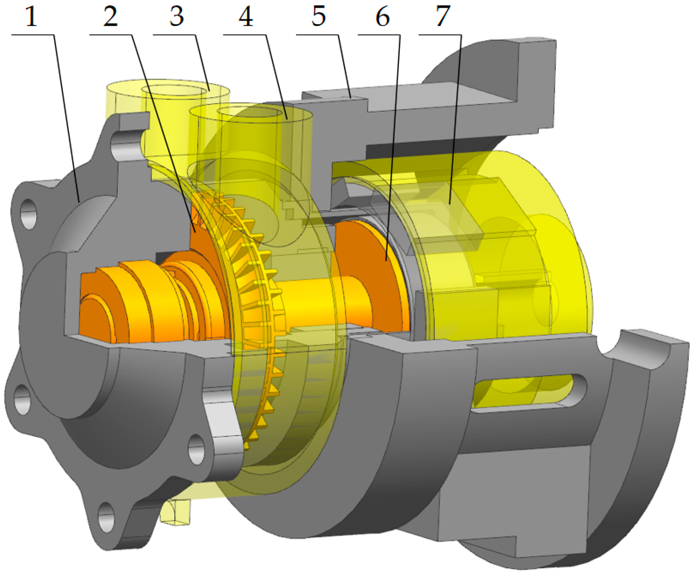
2.2. Magnetic Vortex Pump Modeling and Structural Parameters

In this study, a magnetic vortex pump with a closed impeller and an open channel was investigated. Based on its geometric parameters, the magnetic vortex pump was modeled using the 3D software UG NX 12.0. The model primarily consisted of the inlet, outlet, impeller, inner and outer rotors, pump body, and pump cover. Figure 1 provides a schematic diagram of the magnetic vortex pump structure, with the main parameters being detailed in Table 2.

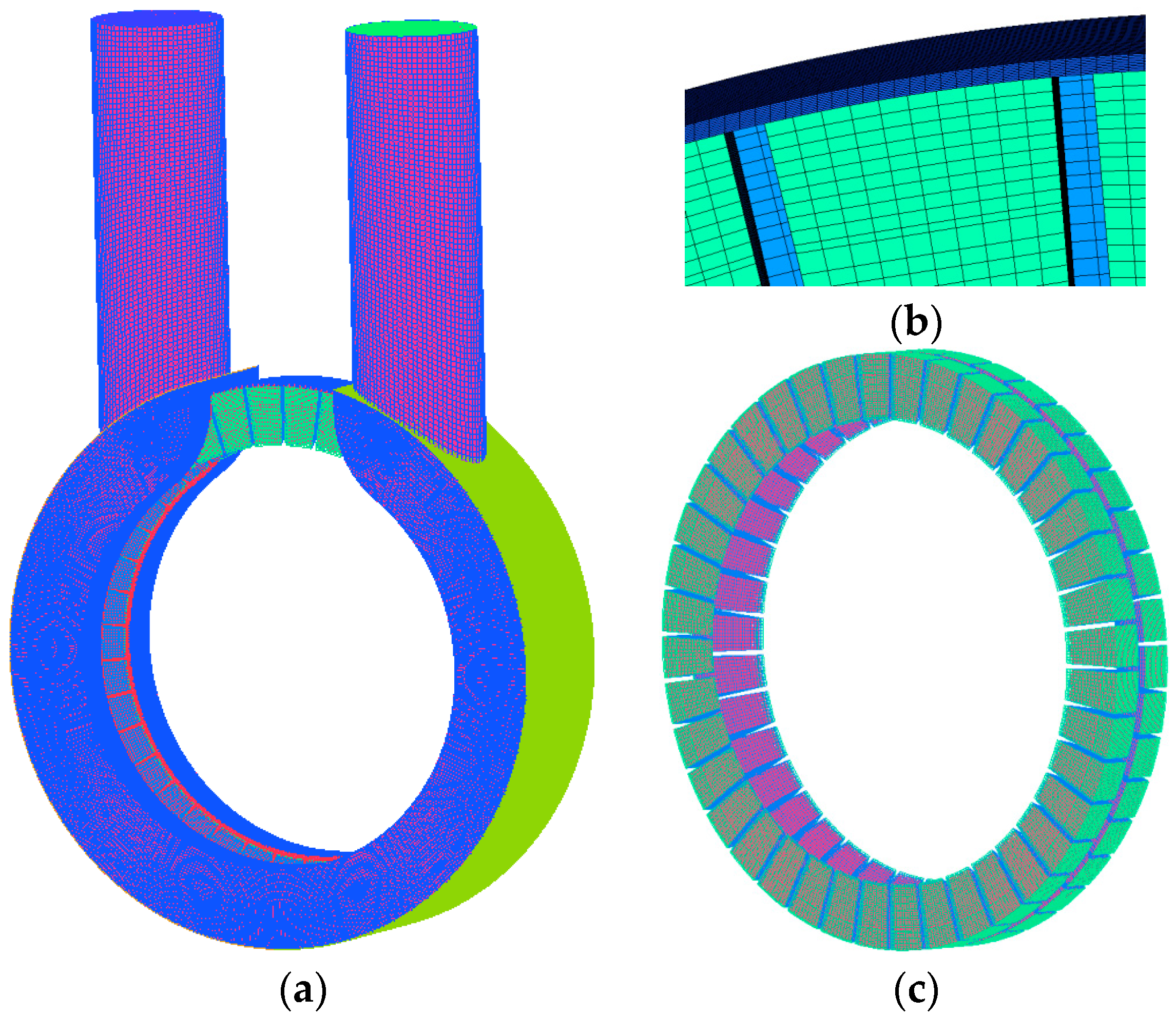
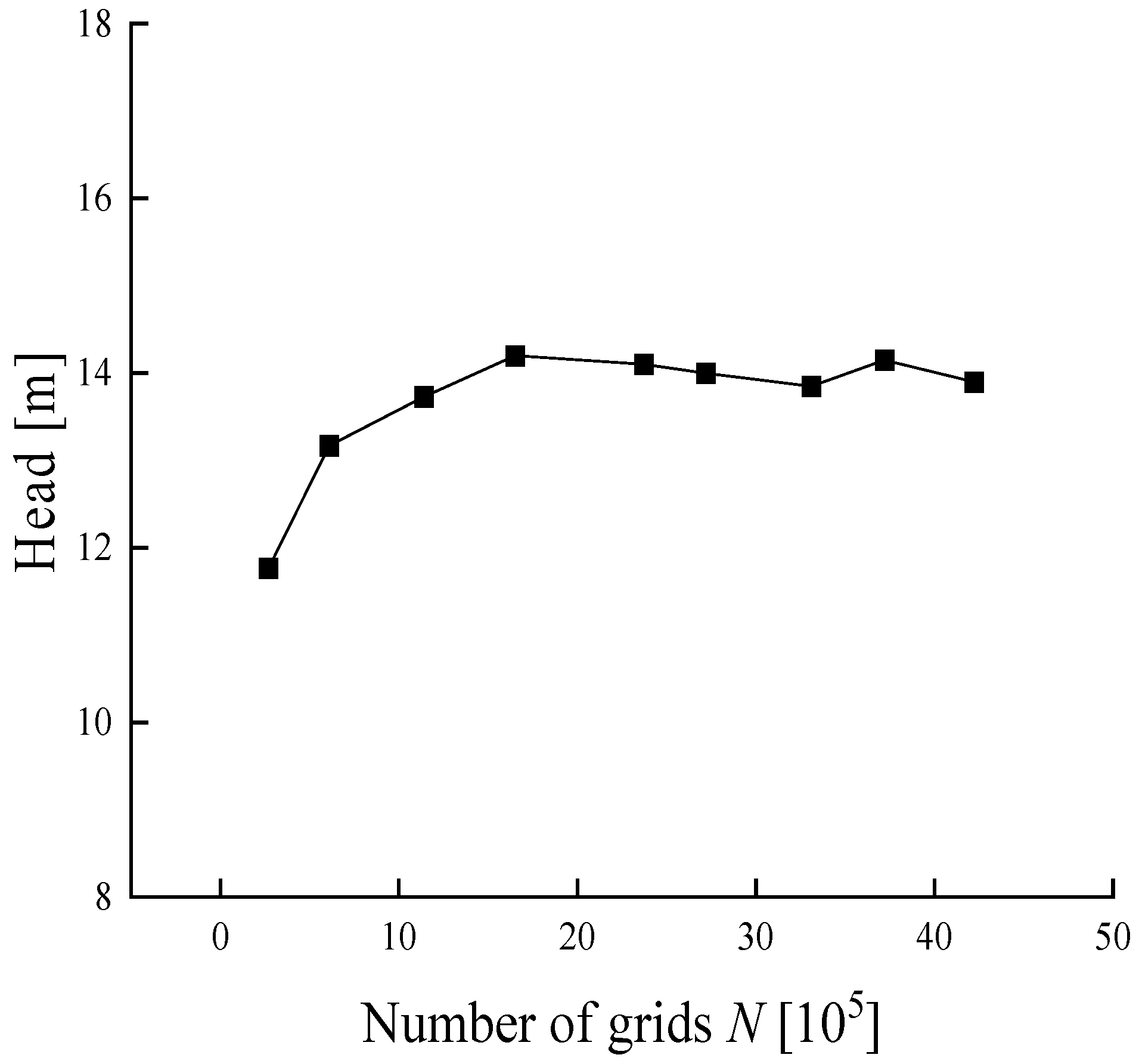
2.3. Computational Grid and Independence Validation

The computational domain of the magnetic vortex pump encompasses the inlet, the impeller, front and rear flow channels, and the outlet. The fluid domain was modeled and extracted using NX UG and SpaceClaim, with extensions being applied to the inlet and outlet sections to ensure comprehensive coverage. The simulation procedure is similar to our previous study [27,28].Given the complexity of the internal flow within the vortex pump, a structured grid was employed throughout the fluid domain to enhance the computational speed and accuracy. The specific grid division is illustrated in Figure 2.
To ensure the accuracy of the numerical simulation, grid independence was verified under conditions where the grid quality met the computational requirements. Using the number of grids N as the independent variable, and the head calculated from the original impeller under the design condition Q = 1.5 m3·h−1 as the dependent variable, we obtained the results shown in Figure 3. When the number of grids exceeded 2 mil., the head trend stabilized, with a maximum deviation of less than 1.8%. Therefore, approximately 2 mil. grids were used for subsequent numerical calculations.

2.4. Turbulence Model and Calculation Setup

In this study, Ansys Fluent 2022 R1 software was used to solve the conservation of mass equations for incompressible flow control, and the RNG k-ε model was chosen as the turbulence model. The RNG k-ɛ model is an improved standard k-ε model proposed by Yakhot and Orzag. The expression is presented below:
t ρ k + x i ρ k u i = x i α k μ e f f k x j + G b + G k ρ ε Y m + S k
ρ ε t + ρ ε u i x i = x i α ε μ e f f ε x j + C 1 ε ε G k + G b C 3 ε K C 2 ε ρ ε 2 k R ε + S ε
where C1ɛ = 1.42, C2ɛ = 1.68, αk = 1.39, and αɛ = 1.39.
The effective turbulent viscosity CV = 100 at a low Re number and μt at a high Re number can be expressed as follows:
μ t = ρ C μ k 2 ε
μ e f f = μ + μ 1
where Cμ = 0.0845.
The RNG model considers the correction of turbulence viscosity using vortices, and this expression is as follows:
μ t = μ t 0 f α s , Ω , k ε
where μt0 is the unmodified turbulent viscosity; Ω is the characteristic vortex number; αs is the vortex constant; and the slight vortex is 0.07.
Rɛ is a modified term with different gradients or Re numbers, which can be expressed as follows:
R ε = C μ ρ η 3 1 η η 0 1 + β η 3 ε 3 k
η = 2 E i j · E i j 1 / 2 k ε
E i j = 1 2 μ i x j + μ j x i
where η0 = 4.38, and β = 0.012.
The RNG k-ε model includes an additional equation that enhances the accuracy of calculations for rapidly strained flows and accounts for the effects of eddy currents on turbulence, thereby improving the precision of turbulence modeling. RNG theory provides a differential formula for effective viscosity, which explains the low-Reynolds-number effects.
The solution for low-Reynolds-number flow in the near-wall region was managed using Enhanced Wall Treatment. The inlet was set as a pressure inlet with an inlet gauge pressure of 1 atm, while the outlet was configured as a mass flow outlet with a flow rate of 2800 r/min according to different working conditions. The initial state for transient calculations used the results from steady-state calculations, with the impeller rotation set at 1° per time step, equivalent to 0.000059524 s.

2.5. Test Design

To verify the accuracy of the numerical simulation results for the magnetic vortex pump, tests were conducted at the Jiangsu University Mechanical Industry Product Quality Inspection Center. The layout of the test bed is shown in Figure 4.
The inlet and outlet pressure gauges were connected to electronic pressure sensors to measure the inlet and outlet pressures. A motor sensor read the rotational speed and motor input power. A pressure stabilizing tank was used to increase the total volume of fluid in the system, reduce the fluid circulation velocity in the closed test stand, and ensure that the measured data were more stable and accurate. It also controlled and adjusted the pressure throughout the system. Parameters such as head, flow rate, pump efficiency, and speed were fed back to the control room computer for monitoring and analysis.

3. Results and Analysis

This chapter analyzes the external characteristics, internal flow field distribution, and blade-tip clearance leakage flow of the magnetic vortex pump at different working fluid temperatures. The vorticity intensity equation is introduced to qualitatively and quantitatively evaluate the vorticity distribution within the internal flow field.

3.1. Verification of Numerical Calculations

To verify the accuracy of the numerical simulation of the magnetic vortex pump, a steady-state simulation was conducted using water as the medium under standard operating conditions with the original impeller. The resulting head curve was compared with experimental data, as shown in Figure 5. As the flow rate increased, the difference between the simulated head and the measured head decreased. With further increases in the flow rate, the rate of the decline in both the simulated and measured heads gradually slowed. When the flow rate exceeded 1.6 m3/h, cavitation occurred in the vortex pump at high flow rates, causing the experimental head curve to decline at a greater rate than in the simulation. However, the overall trend of the head curve decline was consistent, with a head error of 2.37%. Therefore, the numerical simulation was found to be reliable, and the results could be used as a basis for further analysis.

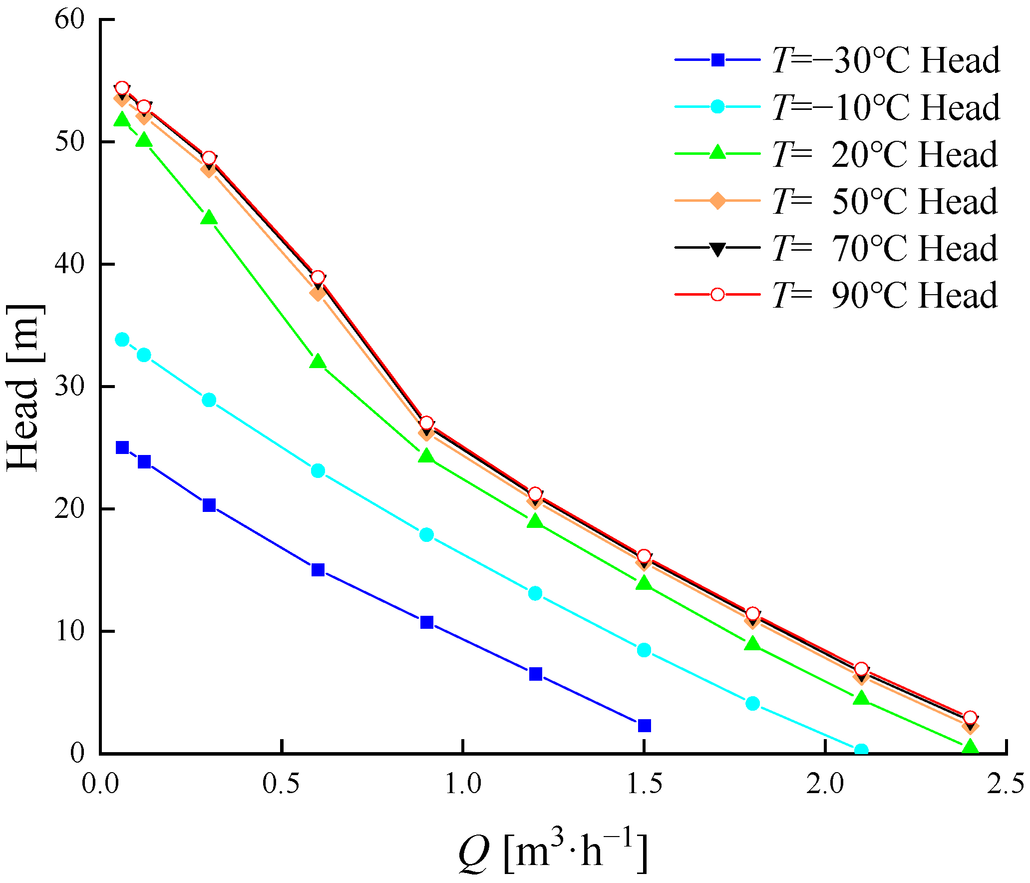
3.2. Analysis of External Characteristics under Different Working Fluid Temperatures

As shown in Figure 6, the head curves at different working fluid temperatures demonstrate a downward trend with the increasing flow rate. The head curve for higher working fluid temperatures is higher than that for lower temperatures, and the gap between the head curves at different temperatures narrows as the temperature increases. The head curves at −30 °C and −10 °C show a relatively stable and approximately linear decline with the increasing flow rate. At room temperature, the head curve declines rapidly at low flow rates, but the rate of this decline decreases and stabilizes as the flow rate increases. For temperatures of 70 °C and 90 °C, the head decline rate increases gradually when the flow rate is less than 0.9 m3/h, and then decreases and stabilizes when the flow rate exceeds 0.9 m3/h.
According to Table 1, the dynamic viscosity (μ) differences between adjacent temperatures are 0.01424, 0.00322, 0.00081, and 0.00043 kg/m·s for −10 °C, 20 °C, 50 °C, 70 °C, and 90 °C, respectively. The ratio of these dynamic viscosity differences is approximately 33.1:7.5:1.9:1. In comparison, the head differences between adjacent temperatures at the design flow rate are 6.1423, 5.3639, 1.778, 0.3498, and 0.1772, with a ratio of approximately 30.3:10:2:1. This comparison reveals that when the viscosity is less than about 0.02 kg/m·s, the ratio of dynamic viscosity differences is close to the ratio of the calculated head differences. Additionally, for higher flow rates, the slope of the linear fit of the head curve becomes similar. For working fluid temperatures above −10 °C, the slope of the curve is −15.97 ± 0.05. Therefore, it is hypothesized that for a 60% ethylene glycol solution at temperatures above −10 °C and under high-flow conditions, the calculated head difference is positively correlated with the dynamic viscosity difference in the medium.
Figure 7 shows the pump efficiency curves at different working fluid temperatures. As the flow rate increases, the efficiency initially rises and then decreases, with the curve sharply declining after reaching the maximum efficiency point. When the working fluid temperature increases, the pump efficiency also increases, and the point of maximum efficiency shifts towards higher flow conditions. As the working fluid temperature rises, the efficiency curves elevate, and the differences between the efficiency curves diminish.

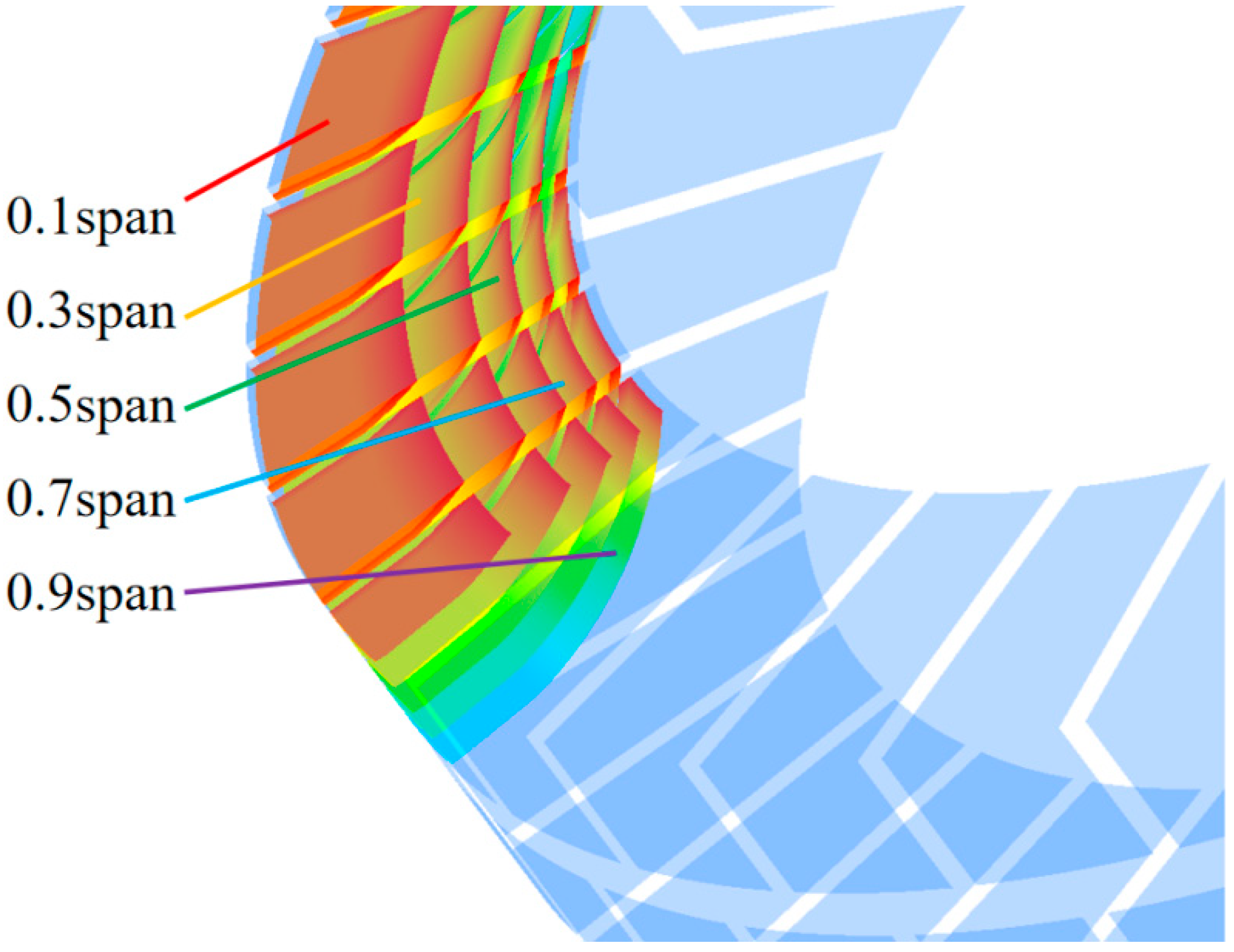
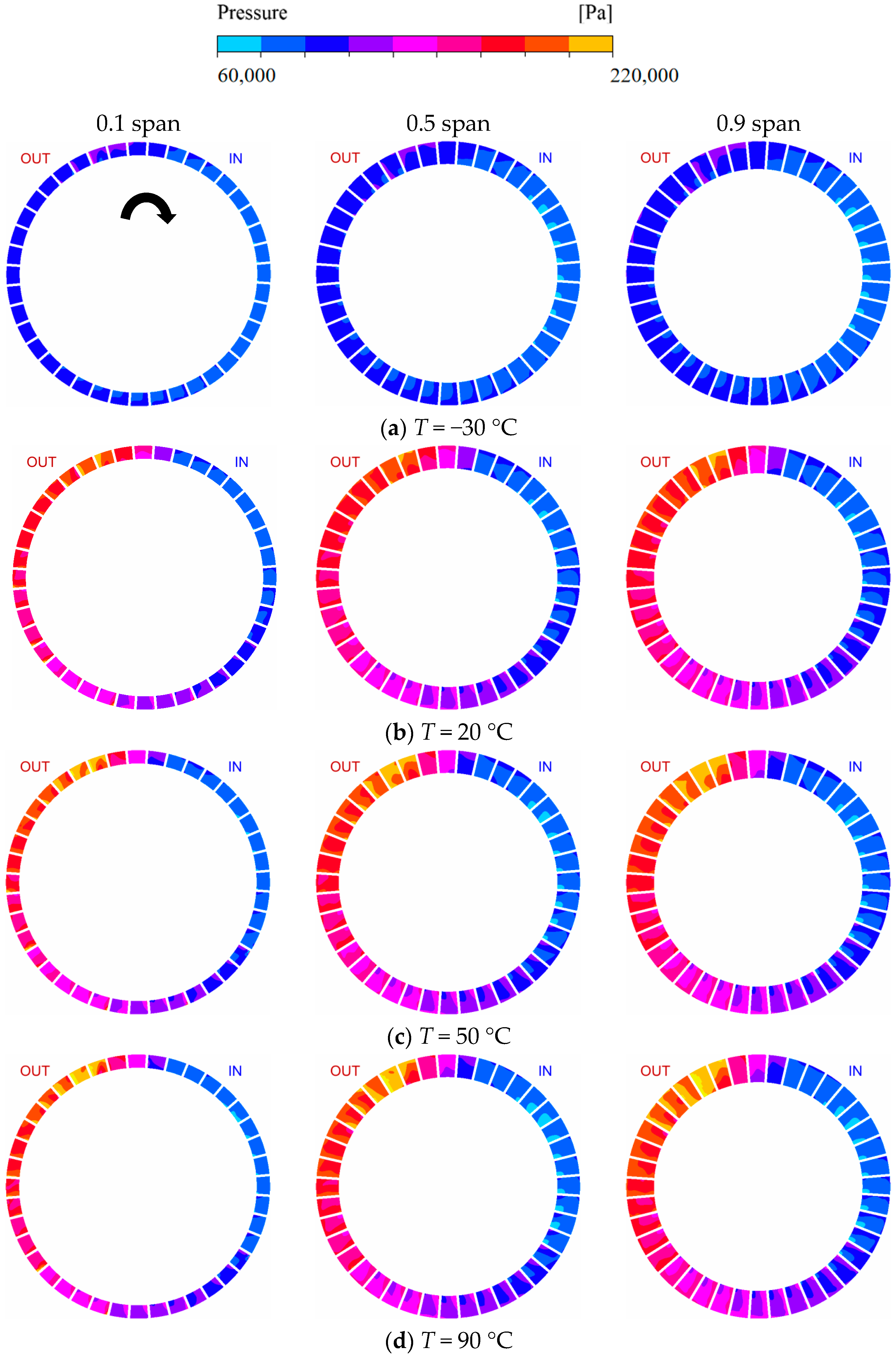
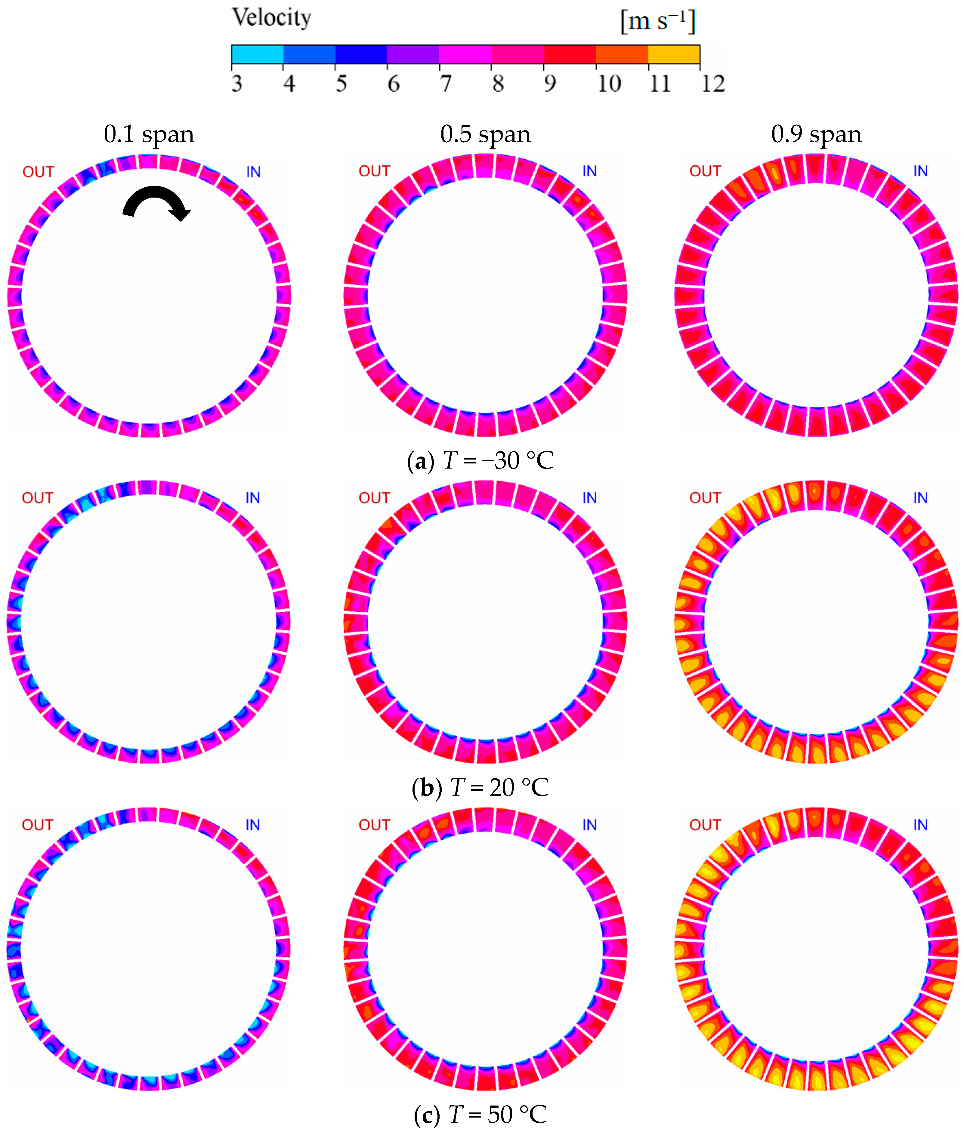
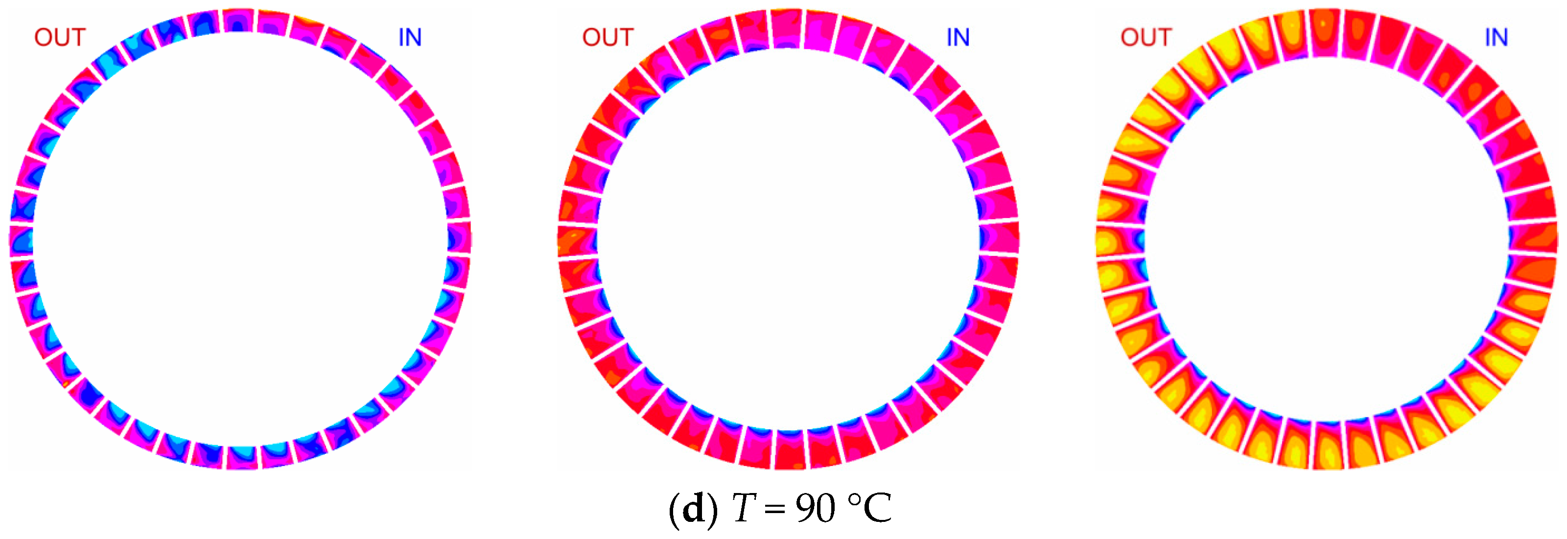
3.3. Pressure and Velocity Distribution in the Internal Flow Field

To compare the internal flow field distribution of the magnetic vortex pump at different working fluid temperatures, multiple flow surfaces were established along the Z-axis within the impeller channel, from the interface between the impeller and the outer channel to the interface between the impeller and the side channel. The specific division method is illustrated in Figure 8. A span of 0.1 represents that the intersection line of the flow surface and the outer channel is at a distance of 0.1 times the blade width from the side channel interface, with other sections following the same principle.
Figure 9 compares the pressure distributions on three flow surfaces at different working fluid temperatures: near the hub (0.1 span), near the side passage (0.9 span), and inside the impeller passage (0.5 span) along the Z-axis. The pressure on the pressure side of the impeller blades is higher than that on the suction side, and the pressure increases from the inner diameter to the outer diameter along the flow surfaces. A negative-pressure zone forms at the suction side near the inlet, which, while beneficial for drawing fluid into the impeller’s working area, is prone to cavitation. The pressure gradient at the middle section (0.5 span) and near the hub (0.9 span) is significantly higher than that near the side channel (0.1 span). Therefore, cavitation is likely to occur at the inner diameter on the suction side of the impeller near the inlet. The positive pressure gradient develops from the inlet along the impeller’s rotation direction, reaching a maximum at the outlet channel. In the tongue area, the pressure drops sharply from the outlet channel to the inlet channel, and the pressure variation trends are consistent across all flow surfaces. As the working fluid temperature increases, the maximum pressure on the same flow surface also increases, the pressure rise in the adjacent impeller passages increases, and the rate of fluid energy accumulation in the impeller passage increases. Additionally, the low-pressure area near the inlet expands at 50 °C and 90 °C.
Figure 10 shows the velocity distributions at spans of 0.1, 0.5, and 0.9 for different working fluid temperatures. Overall, the low-speed zones in the impeller passage are primarily near the inner diameter, close to the side channel interface. The low-speed zone at the 0.1 span near the side channel significantly expands, and the overall velocity increases as the flow surface approaches the hub. The low-speed zone at the inlet for the 0.1 span is smaller, while the low-speed zone at the outlet is larger. In the tongue area, the fluid velocity gradually increases along the impeller’s rotation direction, with minor differences in velocity distribution in other regions of the impeller passage. At the 0.5 span within the impeller passage, the velocity variation in the tongue area is minor, and the velocity distribution outside the tongue area is similar. At the 0.9 span, the fluid velocity decreases along the impeller’s rotation direction, with lower velocities near the inlet compared to other regions. Low-speed fluid from the volute channel enters the impeller passage near the inner diameter, accelerating as it flows. After momentum exchange between the fluid at the impeller’s outer diameter and the volute-channel fluid, the velocity of the fluid near the outer diameter starts to decrease. Comparing different working fluid temperatures, as the working fluid temperature increases, momentum exchange at the flow channel interfaces intensifies. The distribution range of low-speed zones at the inner diameter of the 0.1 span and high-speed zones at the outer diameter of the 0.9 span increases, and the sectional velocity gradient gradually enlarges. Since the 0.5 span is located within the impeller passage, the fluid velocity on this surface is strongly correlated with the impeller’s rotational speed due to inertial and viscous forces, resulting in minor velocity distribution differences across different working fluid temperatures at the 0.5 span.

3.4. Analysis of Radial Clearance Leakage Flow at Different Working Fluid Temperatures

According to Figure 11, the trajectories of blade-tip leakage flow at different working fluid temperatures indicate that the speed of radial clearance blade-tip leakage flow and the formation of leakage vortices in the tongue area change with an increasing working fluid temperature. Additionally, their spatial distribution varies after exiting the tongue area. At a working fluid temperature of −30 °C, the fluid flow speed in the blade-tip region is relatively slow. When this fluid comes into contact with the high-speed fluid within the impeller passage, it forms radial vortices through entrainment, resulting in a low-speed flow zone at the radial interface of the impeller passage. The fluid near the blade wall accelerates under the influence of the rotating impeller. After exiting the tongue area, almost all of the blade-tip leakage flow enters the side channel and impeller passage, participating in momentum exchange within the flow channel. As the working fluid temperature rises to 20 °C, the leakage flow speed increases, with even higher speeds occurring near the impeller wall. More fluid enters the blade-tip clearance area during flow, and after leaving the tongue area, part of the leakage flow experiences flow separation and enters the outer channel circumferentially, affecting the incoming flow in the channel. When the working fluid temperature reaches 50 °C, the decrease in fluid density and viscosity leads to increased pressure energy near the outlet. The speed and volume of leakage flow entering the blade-tip clearance area further increase, and the circumferential leakage flow entering the outer channel develops in speed and flow distance. At a working fluid temperature of 90 °C, the speed and volume of the leakage flow reach their maximum. The fluid speed near the impeller wall exceeds that of other conditions, and the leakage flow entering the outer channel achieves the highest speed, volume, and impact on the incoming flow at the inlet among all conditions. This causes radial flow to significantly affect the incoming flow, exacerbating energy loss.
To quantify the leakage flow intensity and compare the leakage flow intensity levels in the tip clearance area observed at different working fluid temperatures, the leakage flow per unit area of different cross-sections is defined as follows:
Q i = ρ v r e n d A i d A i
where n is the cross-sectional normal vector; vre is the relative velocity through the cross-section, m2/s; and Ai is the cross-sectional area.
Figure 12 shows the distribution of blade-tip leakage flow intensity levels at different working fluid temperatures. The blade-tip clearance area is divided based on circumferential length, defining the total length of the clearance region as λ. From the outlet channel interface at the start, moving along the impeller rotation direction to the inlet channel interface, it is defined as 0~1λ. The leakage flow intensity is analyzed for different area elements within the radial blade-tip clearance cross-sections at 0.1λ, 0.5λ, and 0.9λ. The figure shows that as the working fluid temperature increases, the intensity of the leakage flow through each cross-section gradually increases, with a noticeably higher intensity near the blade wall of the impeller passage.
As shown in Figure 13, the leakage flow at the 0.1λ, 0.5λ, and 0.9λ cross-sections at different working fluid temperatures was calculated and quantitatively analyzed in conjunction with Figure 12. It can be observed that at −30 °C, the leakage flow distribution is different from that under other conditions. The leakage flow intensity near the outlet cross-section is greater than that of other cross-sections. This is due to the relatively small variation in pressure energy within the blade-tip clearance area at low temperatures, resulting in slower leakage flow velocity. This slower leakage flow is entrained by the high-speed fluid in the passage, causing some leakage flow to be drawn into the impeller passage. Consequently, the leakage flow intensity near the clearance outlet is less than that near the clearance inlet. Under high-temperature conditions, as the working fluid temperature increases, the leakage flow intensity gradually increases. The leakage flow intensity at the 0.1λ to 0.9λ cross-sections also increases progressively. This is because a greater pressure energy gradient in the blade-tip clearance area during energy conversion results in greater acceleration of the leakage flow. Hence, the leakage flow intensity increases with higher working fluid temperatures and larger λ values.

3.5. Energy Distribution and Vorticity Comparison in the Internal Flow Field

Here, we analyze the distribution of pressure energy in the impeller flow passage at different working fluid temperatures and provide a qualitative and quantitative evaluation of the vorticity distribution in relatively stable flow regions.

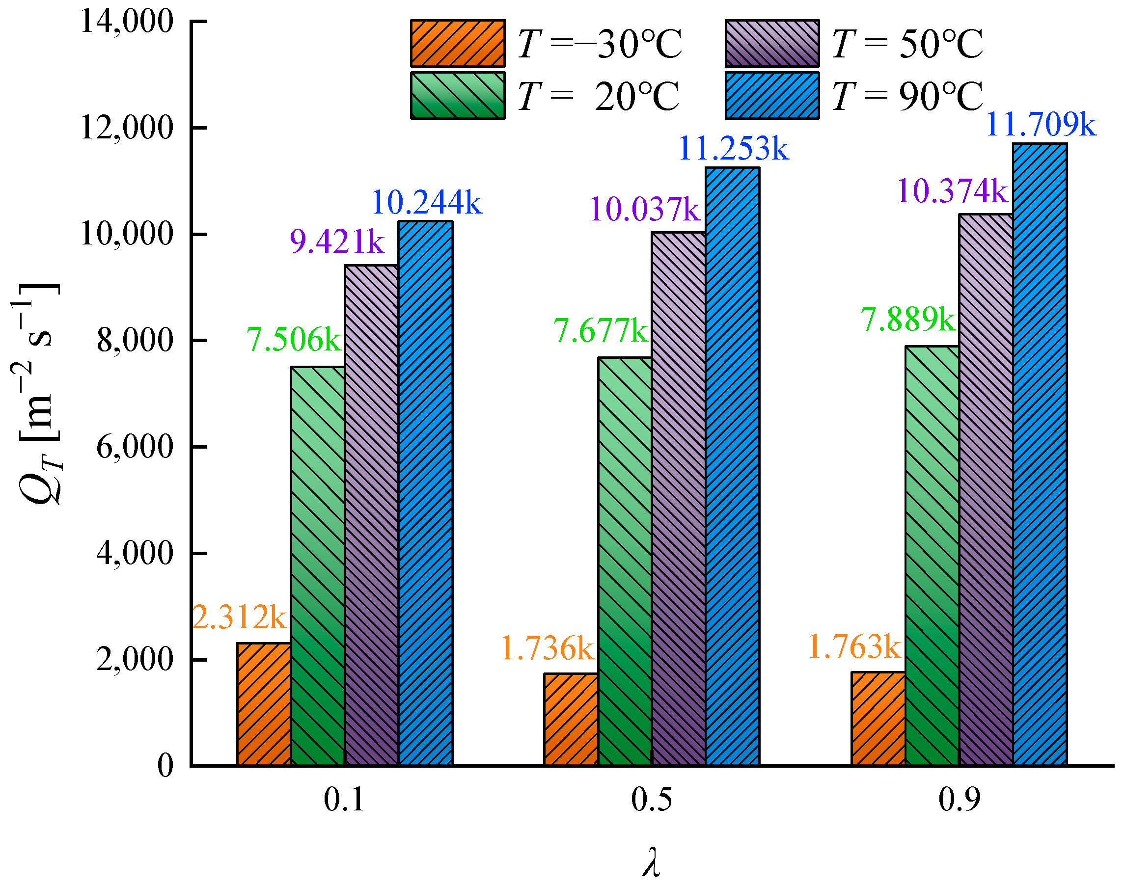
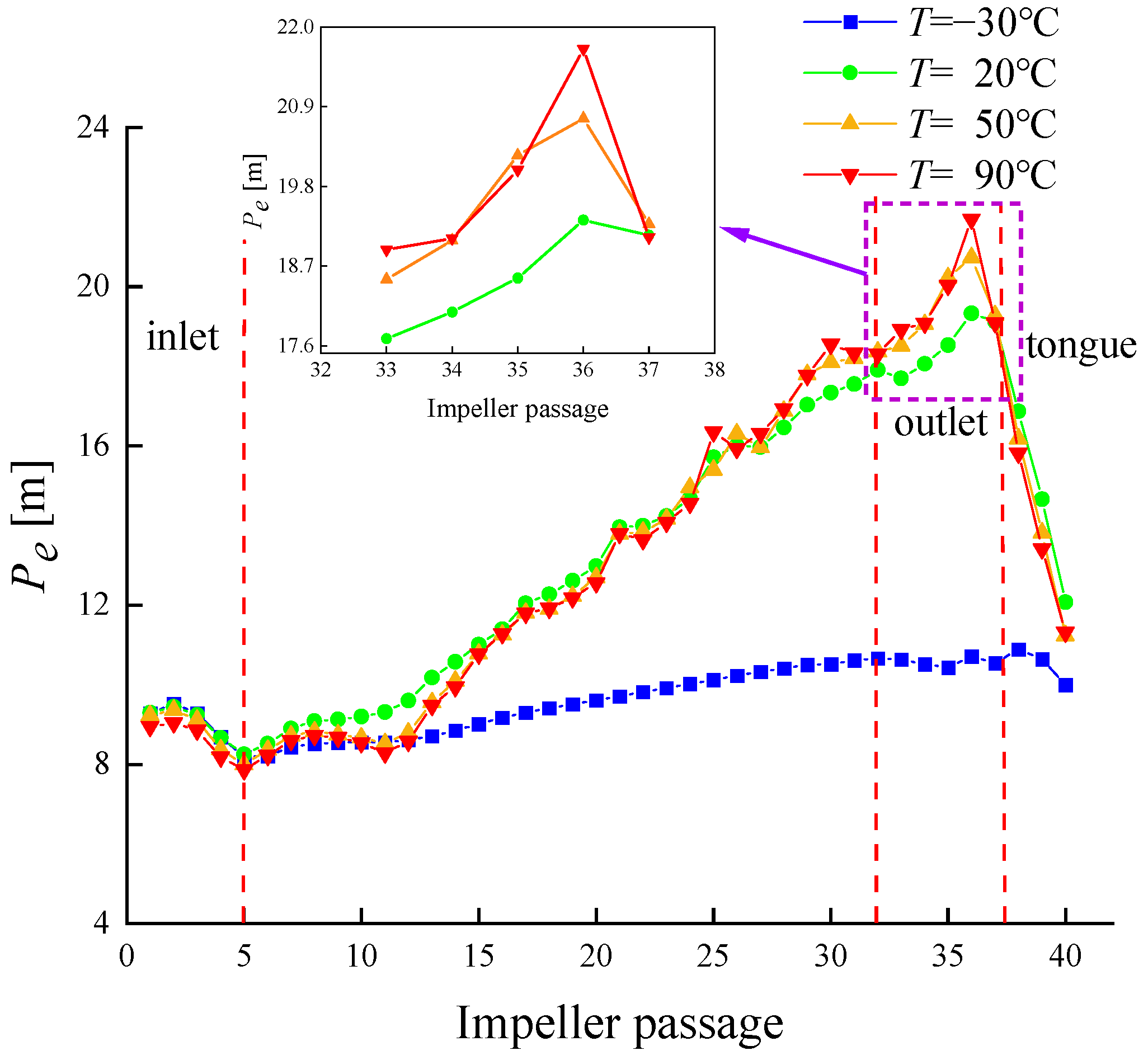
3.5.1. Energy Distribution in the Internal Flow Field

Figure 14 shows the average pressure energy variation curves along the impeller passage in the direction of impeller rotation under the design flow conditions at different media temperatures. The pressure variation trend in the impeller passage at the inlet region is consistent. Analysis of the leakage flow at the inlet channel indicates that as the media temperature increases, the degree of leakage flow interference gradually intensifies. Therefore, in the inlet region, the pressure energy curve for lower media temperatures is positioned above that for higher media temperatures.
At a media temperature of −30 °C, due to the higher fluid density and viscosity, the overall pressure energy curve is significantly lower than the curves for temperatures between 20 °C and 90 °C. The pressure energy peak at the outlet channel and the rate of the decrease in pressure energy in the tongue area are both smaller. As the media temperature increases, the pressure energy rises at a gradually increasing rate, and the amplitude of the curve fluctuations becomes larger. The pressure energy curve reaches its peak at the outlet channel, and this peak gradually increases with higher media temperatures. After entering the tongue area, the pressure energy in the channel sharply decreases until it approximates the pressure energy at the inlet channel.

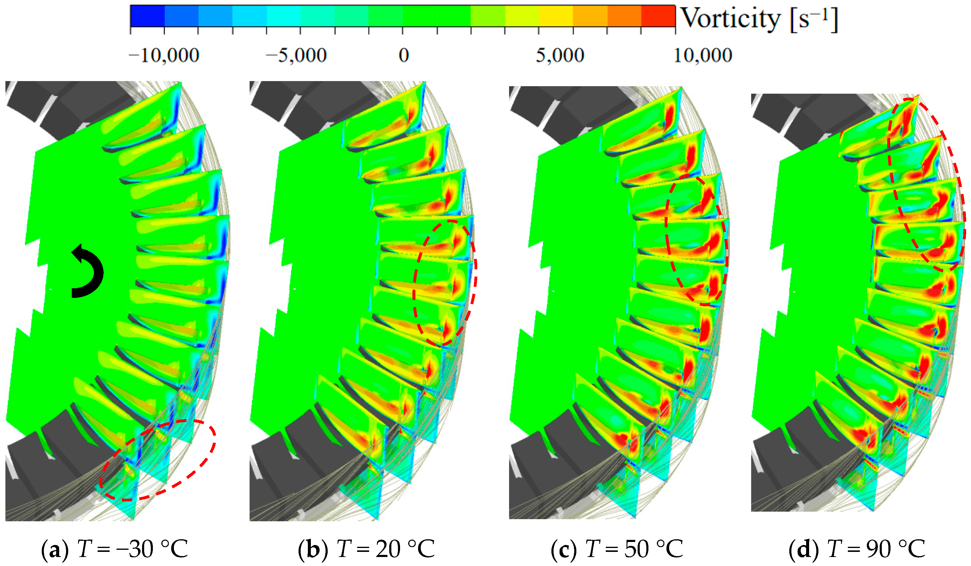
3.5.2. Analysis of Vorticity and Intensity at Different Working Fluid Temperatures

To analyze the vorticity and intensity at different media temperatures, the flow field in a relatively stable region was selected. The analysis region was defined with the starting cross-section at 0 arc and the ending cross-section at 1 arc. Intermediate sections were defined based on their proportion to the total rotational angle. Nine sections, each with a total rotational angle of 72°, were analyzed, with the 1-arc cross-section forming a 75° angle with the positive Y-axis. The specific analysis region is illustrated in Figure 15.
Figure 16 shows the longitudinal cross-sectional vorticity distribution under different working fluid temperatures. Overall, it can be observed that flow separation occurs in the outer channel as the fluid moves along the impeller’s rotational direction. Part of the fluid enters the impeller channels on both sides, forming a helical motion. As the working fluid temperature increases, the vorticity within the analyzed cross-section gradually increases. At a working fluid temperature of −30 °C, the vorticity is concentrated in the radial extension region of the hub in the outer channel and near the outer wall of the volute. The vorticity in the impeller and side channels is relatively low. When the working fluid temperature increases to 20 °C, the vortices in the radial extension region of the hub and near the outer wall of the volute become fragmented, and the vorticity decreases significantly. Large vortex cores form at the junctions between the impeller, side channels, and outer channel, and the vorticity near the hub within the impeller passage also increases. As the working fluid temperature rises to 50 °C, the increased momentum exchange within the channels results in greater and more continuous vorticity at the side channel interfaces. The scale and vorticity of the vortices at the outer channel interface further increase, extending gradually towards the volute sidewall, and the vortices near the outer wall of the volute disappear. At a working fluid temperature of 90 °C, the decreased density and viscosity of the fluid reduce tangential viscous forces. Under the influence of centrifugal force, the vortices at the impeller and side channel interface develop towards the outer diameter and connect with the vortices at the outer channel interface. The vortices in the outer channel further extend towards the volute sidewall, and the vorticity of the main vortex core continues to increase. The enhanced momentum exchange between the volute channel and the impeller channel results in increased vorticity at the inner diameter of the side channel. Flow separation occurs in the outer channel at 0.75 arc and 0.875 arc, forming separation vortices near the volute outer wall. These analyses indicate that as the working fluid temperature increases, the decreased density and viscosity of the medium reduce the fluid’s viscous forces in all directions. Under the influence of the impeller, the range of high-vorticity-distribution areas at different channel interfaces increases. Additionally, the physical changes in the medium with rising temperatures somewhat inhibit the formation of vortices near the outer wall of the volute.
In order to study the evolution of vortices along the rotating direction of the impeller, the strength of vortices per unit area was analyzed:
Γ = A ω d A
Δ Γ = A ω d A d A
Figure 17 shows the distribution curves of the vorticity intensity per unit area under different working fluid temperatures. According to the figure, as the working fluid temperature increases, the vorticity intensity per unit area gradually increases. At a working fluid temperature of −30 °C, the vorticity intensity per unit area across different arc sections shows minimal variation, with the overall curve exhibiting a slight upward trend. This indicates that the vortex structure distribution within the flow channel is relatively uniform under low-temperature conditions, resulting in a relatively stable internal flow field. When the working fluid temperatures are 20 °C and 50 °C, the overall trend in the vorticity intensity is similar, with some fluctuations in vorticity occurring at sections with larger arcs near the outlet. At a working fluid temperature of 90 °C, the vorticity intensity reaches its maximum, significantly enhancing the mass exchange efficiency of the fluid within the impeller passage. Consequently, the internal fluid undergoes substantial momentum exchange. The vorticity intensity across different sections is greatly affected by the flow state, with high-intensity separation vortices appearing at the 0.75-arc section, leading to a peak in the vorticity intensity curve in this section. These observations suggest that the internal vortex intensity of a magnetic vortex pump can, to some extent, represent the hydraulic performance under specific conditions. As the internal vortex intensity increases, although it may lead to greater turbulent dissipation energy loss, the efficiency of the momentum exchange of the fluid within the pump significantly improves under the influence of the impeller. This ultimately results in enhanced hydraulic performance.

4. Conclusions

The hydraulic performance of a magnetic vortex pump varies significantly with different working fluid temperatures. This study investigated multiple working fluid temperatures ranging from −30 °C to 90 °C using a combination of numerical simulation and experimental validation. Through the analysis of pressure, velocity, radial clearance flow, energy distribution, and vorticity, the following conclusions were drawn:
  • As the working fluid temperature increases, both the head curve and efficiency curve of the magnetic vortex pump rise to varying degrees. At the design flow rate, compared to normal conditions (20 °C), the head increases by 16.7% and the pump efficiency increases by 4.11% at 90 °C. Conversely, when the fluid temperature drops to −30 °C, the head is only 16.8% of that at normal conditions, and the pump efficiency decreases by 24.82%. This indicates that low working fluid temperatures have a significantly negative impact on the hydraulic performance of a magnetic vortex pump, providing valuable insights for designing the working fluid temperature range of magnetic vortex pumps.
  • For a 60% ethylene glycol–water solution, the head differences at the same flow rate across different working fluid temperatures are positively correlated with the differences in dynamic viscosity at those temperatures when the working fluid temperature is above −10 °C. This result offers an important basis for evaluating the hydraulic performance of magnetic vortex pumps when transporting automotive antifreeze at various temperatures.
  • Qualitative and quantitative analyses of the radial clearance flow in the vortex pump reveal flow separation at the inlet. As the working fluid temperature rises, the interference of the separation flow with the incoming flow intensifies. The changes in average pressure energy at the inlet across different working fluid temperatures indicate that radial clearance flow interference negatively impacts the energy accumulation of the fluid within the pump. These findings provide critical references for further optimization of the hydraulic performance of magnetic vortex pumps.
  • As the working fluid temperature increases, the scale and magnitude of the vorticity distribution within the internal flow field gradually expand. At lower working fluid temperatures, the higher dynamic viscosity of the fluid significantly increases the viscous forces between fluids at the same velocity gradient, inhibiting high-intensity momentum exchange. With rising fluid temperatures, both the dynamic viscosity and density of the fluid decrease, leading to larger and more intense vortices in the internal flow field at the same flow rate. These vortices facilitate thorough momentum exchange within the flow channels, thereby improving the head and efficiency of the magnetic vortex pump. Understanding the impact of the working fluid temperature on the hydraulic performance of magnetic vortex pumps lays the groundwork for subsequent structural optimization during variable-temperature transportation and flow control research under extreme-temperature conditions.

Author Contributions

Conceptualization, Y.C. and L.J.; methodology, Y.C.; software, Y.C. and S.M.; validation, Y.C. and Y.L.; formal analysis, Y.C.; writing—review and editing, Y.C., C.X. and L.J.; project administration, W.L.; funding acquisition, W.L. All authors have read and agreed to the published version of the manuscript.

Funding

This work was sponsored by the National Natural Science Foundation of China (No. 52179085, 52309112), Project funded by China Postdoctoral Science Foundation (No. 2022TQ0127, 2023M741414), the Key International Cooperative research project of the National Natural Science Foundation of China (No. 52120105010), the Sixth “333 High Level Talented Person Cultivating Project” of Jiangsu Province, the funded projects of the “Blue Project” within Jiangsu Colleges and Universities, and the Wenling Fluid Machinery Technology Institute of Jiangsu University (No. 01011).

Data Availability Statement

All valid data are reflected in the article and authorized to be used.

Conflicts of Interest

Author Sizhuo Ma was employed by the company Three Gorges Renewables Offshore Wind Power Operation and Maintenance Jiangsu Co., Ltd. The remaining authors declare that the research was conducted in the absence of any commercial or financial relationships that could be construed as a potential conflict of interest.

References

  1. Wang, S.; Li, H.; Fu, J.; Li, B. Design of vortex pump for aero-engine. Sci. Technol. Eng. 2012, 12, 1301–1303+1333. [Google Scholar]
  2. Quail, F.J. A CFD Analysis of a Regenerative Pump; University of Strathclyde: Glasgow, UK, 2007. [Google Scholar]
  3. Zhang, F.; Bohle, M.; Pei, J.; Yan, S.Q.; Fleder, A. Research status and development trend of side channel pump. J. Drain. Irrig. Mach. Eng. 2015, 33, 737–743. [Google Scholar]
  4. Kumar, M.; Venkateshwaran, A.; Kumar, M.; Sreekanth, M.; Jebaseelan, D.; Sivakumar, R. Strength analysis of a regenerative flow compressor and a pump based on fluid-structure coupling. Mater. Today 2022, 51, 1619–1624. [Google Scholar] [CrossRef]
  5. Meakhall, T.; Park, S.O. An improved theory for regenerative pump performance. Proc. Inst. Mech. Eng. Part A 2005, 219, 213–222. [Google Scholar] [CrossRef]
  6. Ritter, C. Ueber Selbstansaugende Kreiselpumpen und Versuche an einer neuen Pumpe dieser; TU Dresden: Dresden, Germany, 1930. [Google Scholar]
  7. Quail, F.J.; Scanlon, T.; Baumgartner, A. Design study of a regenerative pump using one-dimensional and three-dimensional numerical techniques. Eur. J. Mech. B 2012, 31, 181–187. [Google Scholar] [CrossRef]
  8. Yoo, I.S.; Park, M.R.; Chung, M.K. Improved Momentum Exchange Theory for Incompressible Regenerative Turbomachines. Proc. Inst. Mech. Eng. Part A 2005, 219, 567–582. [Google Scholar] [CrossRef]
  9. Verma, R.; Shukla, S.; Birajdar, R.; Tiwari, N. Numerical Simulation of Regenerative Pump. In Fluid Mechanics and Fluid Power–Contemporary Research: Proceedings of the 5th International and 41st National Conference on FMFP 2014; Springer: Delhi, India, 2017; pp. 891–900. [Google Scholar]
  10. Shi, W.; Dong, Y.; Ma, X.; Sha, Y.; Kong, F. Numerical simulation of the influence of channel section shape on the internal flow of vortex pump. Trans. Chin. Soc. Agric. Eng. 2005, 3, 21–23. [Google Scholar]
  11. Isaev, N. The effect of design parameters of the closed type regenerative pump the energy characteristics. Proc. IOP Conf. Ser. Mater. Sci. Eng. 2019, 492, 012026. [Google Scholar] [CrossRef]
  12. Choi, W.C.; Yoo, I.S.; Park, M.R.; Chung, M.K. Experimental study on the effect of blade angle on regenerative pump performance. Proc. Inst. Mech. Eng. Part A 2013, 227, 585–592. [Google Scholar] [CrossRef]
  13. Maity, A.; Chandrashekharan, V.; Afzal, M.W. Experimental and numerical investigation of regenerative centrifugal pump using CFD for performance enhancement. Int. J. Curr. Eng. Technol. 2015, 5, 2898–2903. [Google Scholar]
  14. Nejad, J.; Riasi, A.; Nourbakhsh, A. Nourbakhsh, Parametric study and performance improvement of regenerative flow pump considering the modification in blade and casing geometry. Int. J. Numer. Methods Heat Fluid Flow 2017, 27, 1887–1906. [Google Scholar] [CrossRef]
  15. Nejadrajabali, J.; Riasi, A.; Nourbakhsh, S.A. Flow pattern analysis and performance improvement of regenerative flow pump using blade geometry modification. Int. J. Rotating Mach. 2016, 77, 8628467. [Google Scholar] [CrossRef]
  16. Fleder, A.; Böhle, M. A Systematical Study of the Influence of Blade Length, Blade Width, and Side Channel Height on the Performance of a Side Channel Pump. J. Fluids Eng. Trans. ASME 2015, 137, 121102. [Google Scholar] [CrossRef]
  17. Karanth, V.K.; Manjunath, M.S.; Kumar, S.; Sharma, N.Y. Numerical study of a self priming regenerative pump for improved performance using geometric modifications. J. Fluids Eng. 2015, 5, 104–109. [Google Scholar]
  18. Li, J.S.; Zhou, F.B.; Zhang, Y.F.; Zhang, D.; Liu, C.; Kang, J.H.; Li, N.; Pan, S.L. Effect of working fluid temperature on energy dissipation characteristics of liquid ring vacuum pump. Appl. Therm. Eng. 2024, 236, 121469. [Google Scholar] [CrossRef]
  19. Chao, Q.; Xu, Z.; Tao, J.F.; Liu, C.L.; Zhai, J. Cavitation in a high-speed aviation axial piston pump over a wide range of fluid temperatures. Proc. Inst. Mech. Eng. Part A 2022, 236, 727–737. [Google Scholar] [CrossRef]
  20. Peralta, P.; Wellerdieck, T.; Steinert, D.; Nussbaumer, T.; Kolar, J.W. Ultra-High Temperature (250 °C) Bearingless Permanent Magnet Pump for Aggressive Fluids. IEEE/ASME Trans. Mechatron. 2017, 22, 2392–2394. [Google Scholar] [CrossRef]
  21. Sojoudi, A.; Nourbakhsh, A.; Shokouhmand, H. Establishing a Relationship between Hydraulic Efficiency and Temperature Rise in Centrifugal Pumps: Experimental Study. J. Hydraul. Eng. 2018, 144, 04018011. [Google Scholar] [CrossRef]
  22. Jiang, J.; Li, Y.H.; Pei, C.Y.; Li, L.L.; Fu, Y.; Cheng, H.G.; Sun, Q.Q. Cavitation performance of high-speed centrifugal pump with annular jet and inducer at different temperatures and void fractions. J. Hydrodyn. 2019, 31, 93–101. [Google Scholar] [CrossRef]
  23. Sojoudi, A.; Nourbakhsh, A.; Shokouhmand, H. Experimental evaluation of temperature rise in centrifugal pumps at partial flow rates. J. Braz. Soc. Mech. Sci. Eng. 2018, 40, 183. [Google Scholar] [CrossRef]
  24. Wu, K.P.; Ali, A.; Feng, C.H.; Si, Q.R.; Chen, Q.; Shen, C.H. Numerical Study on the Cavitation Characteristics of Micro Automotive Electronic Pumps under Thermodynamic Effect. Micromachines 2022, 13, 1063. [Google Scholar] [CrossRef] [PubMed]
  25. Li, W.; Wu, P.; Yang, Y.F.; Shi, W.D.; Li, W.Q. Investigation of the cavitation performance in an engine cooling water pump at different temperature. Proc. Inst. Mech. Eng. Part A 2021, 235, 1094–1102. [Google Scholar] [CrossRef]
  26. Li, D.L.; Li, G.Q.; Han, J.H.; Liu, Y.S.; Wu, D.F. Thermodynamic characteristics research of a water lubricating axial piston pump. Proc. Inst. Mech. Eng. Part C 2020, 234, 3873–3889. [Google Scholar] [CrossRef]
  27. Ji, L.L.; Li, W.; Shi, W.D.; Chang, H.; Yang, Z.Y. Energy Characteristics of Mixed-Flow Pump under Different Tip Clearances Based on Entropy Production Analysis. Energy 2020, 199, 1–15. [Google Scholar] [CrossRef]
  28. Ji, L.L.; Li, W.; Shi, W.D.; Tian, F.; Agarwal, R. Effect of Blade Thickness on Rotating Stall of Mixed-Flow Pump Using Entropy Generation Analysis. Energy 2021, 236, 121381. [Google Scholar] [CrossRef]
Figure 1. Structural model of the magnetic vortex pump: 1—pump cover; 2—impeller; 3—inlet; 4—outlet; 5—pump base; 6—internal magnetic rotor; 7—external magnetic rotor.
Water 16 01601 g001
Figure 2. Grid division of the magnetic vortex pump. (a) The whole grid; (b) gap mesh encryption; (c) impeller grid.
Water 16 01601 g002
Figure 3. Grid independence validation.
Water 16 01601 g003
Figure 4. Magnetic vortex pump test bed: 1—surge tank; 2—inlet valve; 3—outlet valve; 4—flowmeter; 5—imported pressure measuring tube; 6—magnetic vortex pump; 7—outlet pressure measuring tube; 8—motor sensor.
Water 16 01601 g004
Figure 5. Head contrast curves for the magnetic vortex pump.
Water 16 01601 g005
Figure 6. Head curves under different working fluid temperature.
Water 16 01601 g006
Figure 7. Efficiency curves at different working fluid temperatures.
Water 16 01601 g007
Figure 8. Flow surface division diagram of the impeller runner.
Water 16 01601 g008
Figure 9. Pressure distribution on the surface of fluid flowing at different working fluid temperatures.
Water 16 01601 g009
Figure 10. Velocity distribution on flow surfaces at different working fluid temperatures.
Water 16 01601 g010aWater 16 01601 g010b
Figure 11. Tip leakage flow trajectories at different working fluid temperatures.
Water 16 01601 g011
Figure 12. Intensity distribution of the tip leakage flow under different working fluid temperatures.
Water 16 01601 g012
Figure 13. Contrast of leakage flow intensity levels with different working fluid temperatures.
Water 16 01601 g013
Figure 14. The pressure along the impeller passage can vary at different working fluid temperatures.
Water 16 01601 g014
Figure 15. Sketch of the vortex analysis region.
Water 16 01601 g015
Figure 16. Vorticity distribution at different working fluid temperatures.
Water 16 01601 g016
Figure 17. Curves showing the vortex intensity distribution per unit area.
Water 16 01601 g017
Table 1. The physical parameters of the 60% ethylene glycol aqueous solution.
TemperatureDensitySpecific HeatThermal ConductivityDynamic Viscosity
T/°Cρ/kg·m−3Cp/J·kg−1·K−1K/W·m−1·K−1μ/kg·m−1·s−1
−301103.5428660.3120.06525
−101098.0929530.3290.01962
201086.2730840.3490.00538
501070.0632150.3650.00216
701056.8333020.3720.00135
901041.6533890.3770.00092
Table 2. Main parameters of the magnetic vortex pump.
ParameterDesign FlowImpeller SpeedImpeller DiameterNumber of LeavesInlet
Diameter
Outlet Diameter
SymbolQnDZDinDout
Unitm3·h−1rad·min−1mmunitmmmm
Value1.5280061.54014.814.8
Disclaimer/Publisher’s Note: The statements, opinions and data contained in all publications are solely those of the individual author(s) and contributor(s) and not of MDPI and/or the editor(s). MDPI and/or the editor(s) disclaim responsibility for any injury to people or property resulting from any ideas, methods, instructions or products referred to in the content.

