Abstract
The horizontal displacement of the soil at the face of the subway tunnel is symmetrically distributed along the central axis of the tunnel, which is larger in the middle and smaller at both sides. The displacement is related to the size of the excavation face. If the excavation area is too great, the horizontal displacement of the tunnel face will be too large, easily leading to tunnel face collapse. For this reason, tunnel builders often use the core-keeping ring-cut method to build subway tunnels. A large section is divided into several small sections to reduce the soil displacement caused by soil excavation. With the continuous promotion and application of mechanized construction in the field of tunnels, mechanized full-section construction will gradually be performed in urban subway tunnels. Once the change in construction method from the core-keeping ring-cut method to the full-face method is made, the issue of how to maintain the stability of the tunnel working face (especially the soft soil stratum) becomes the focus of attention. Taking silty clay as the research object, this paper studies the displacement law of core soil with regard to the tunnel face under the condition of full-face excavation by using theoretical analysis, numerical simulations, and outdoor tests. According to the research results, the extrusion displacement of the tunnel face is the main cause of tunnel displacement. We optimize the construction parameters of glass fiber anchors to strengthen the tunnel face and provide theoretical guidance for the safe construction of subway tunnels.
1. Introduction
Tunnel sections generally have a round, oval, or horseshoe shape, where an axisymmetric structural design is more conducive to bearing the geotechnical load. Subway tunnels are built in cities, their construction environment is complex, and the displacement of strata caused by construction is strictly controlled. Therefore, tunnel builders generally choose to divide the tunnel section into several small sections to reduce the disturbance of soil excavation to the stratum. The core-keeping ring-cut method is a common subway tunnel construction approach [1,2], but when the subway tunnel undergoes mechanized construction, this does not provide the best efficiency for mechanical construction, and the full-face method will eventually be used. The core soil is no longer reserved when the full-face method is used. This is not conducive to control of the extrusion displacement of tunnel face. However, the use of mechanized construction shortens the closing time of the initial support and the exposure time of the tunnel face, and is beneficial to the control of tunnel displacement. Thus, the issue of how to maintain the stability of the tunnel face is the focus of full-face construction in subway tunnels.
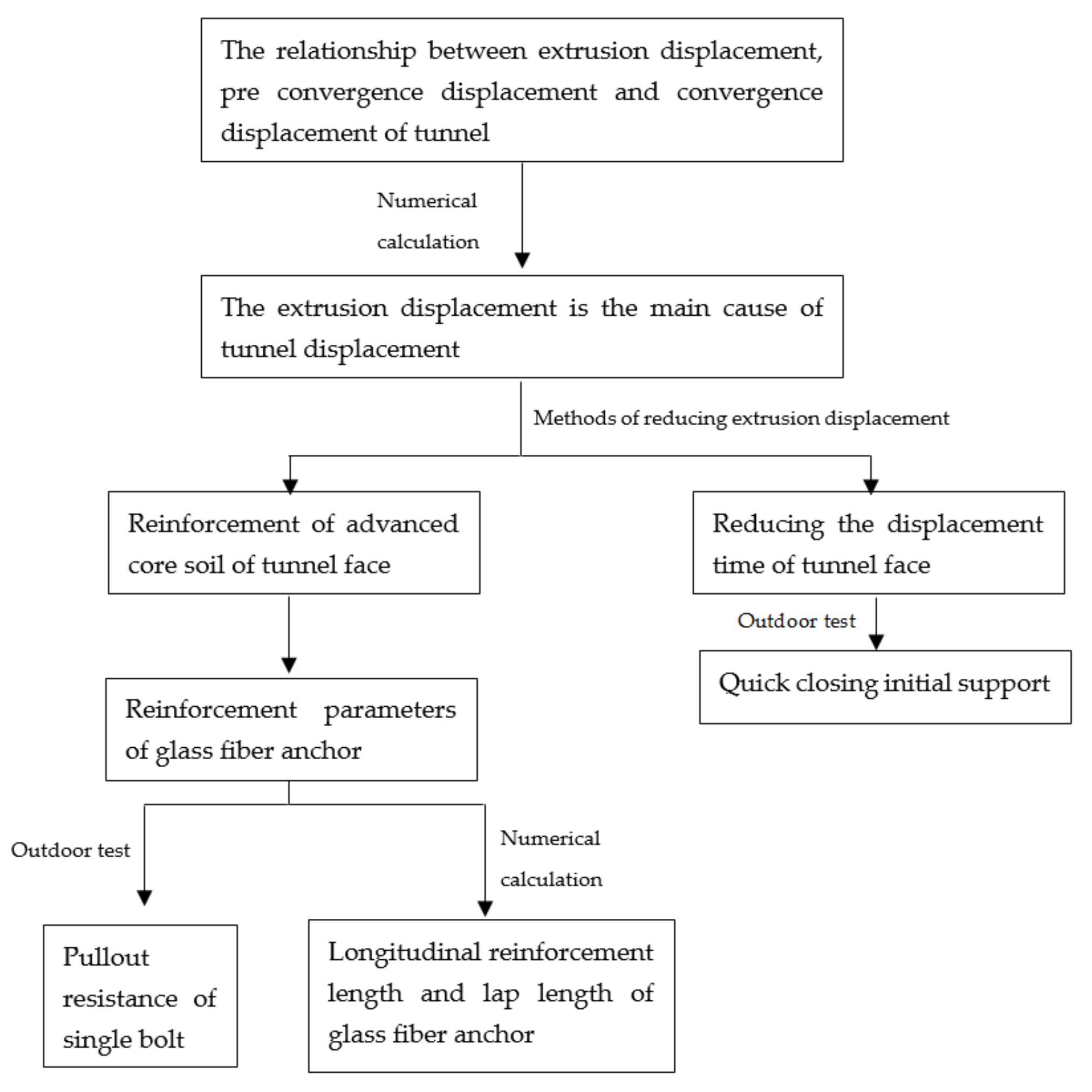
Professor Pietro Lunardi [3,4,5] proposed that the strength and displacement characteristics of advanced core soil were the real inducers of tunnel displacement, and recommended the analysis of controlled displacement in rocks and soils method (ADECO-RS), which has been successfully applied to the full-face construction of many railway tunnels but has rarely been applied in the construction of urban shallow metro tunnels. Horn [6] reported that the tunnel face would form a sliding surface at a specific position after failure. Assuming the shape of sliding surface and yield condition of soil, the support force of tunnel face failure can be deduced by static and torque balance calculations. This author assumed that the soil in the front of the tunnel face would be composed of prism and wedge. Based on the wedge model, Jancsecz and Steiner [7] obtained the minimum ultimate support force expressed by the three-dimensional soil pressure coefficient Ka3d considering the influence of the tunnel soil arch effect. Based on the geostress theory of Terzaghi, Li [8] obtained the ultimate support pressure of a shallow tunnel face in a clay soil layer by using a nonlinear minimum optimization algorithm. Based on the limit analysis method and strength reduction method, Chen et al. [9] derived the functional formula for solving the stability coefficient of tunnel. An et al. [10] used the limit analysis method to derive the stability coefficient of the tunnel face, and determined the influencing law of excavation footage with regard to the stability of the tunnel face. Based on the strength reduction theory, Du et al. [11] reported on the displacement mutation or plastic strain energy as the basis for judging the stability of the tunnel face. Based on the limit equilibrium theory and horizontal slice method, Wang et al. [12] deduced the calculation method of the limit support force of the tunnel face. Based on the research of the above scholars, we chose subway tunnels in a soft soil layer as the research object, and used the methods of theoretical analysis, numerical calculations, and orthogonal experiments to analyze the law characteristics of pre-convergence displacement, extrusion displacement, and convergence displacement of the tunnel after the core soil is excavated, while also considering the reinforcement measures of the tunnel face. The research approach of this paper is shown in Figure 1.
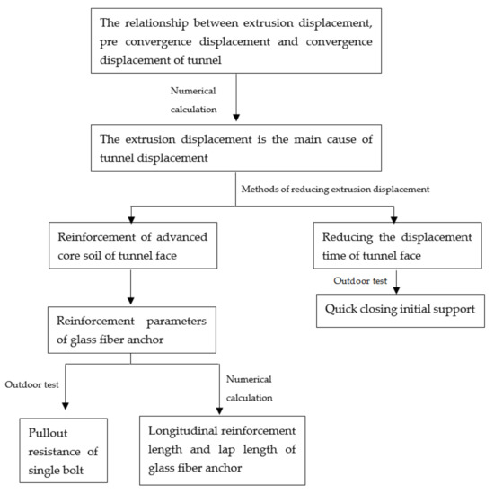
Figure 1.
Research flow chart.
2. Displacement Mechanism of the Soft Soil in Full-Face Excavation
Tunnel displacement during construction includes pre-convergence displacement, extrusion displacement of the tunnel face, and convergence displacement. Extrusion displacement refers to the horizontal displacement of the soil at the tunnel face. After the excavation of the tunnel face, the soil stress on the free face is zero (i.e., б3 = 0). The soil element changes from the triaxial stress state to the plane stress state, and will move towards б3 = 0 to restore the stress balance. Affected by the soil displacement of the tunnel face, although the soil in the affected area is in the state of triaxial stress, the stress is unbalanced, and the soil deforms towards the direction of the minimum principal stress б3. Under the condition that the initial stress of the soil is determined, the displacement is related to the strength of the advanced core soil and the distance from the tunnel face. If the strength is low and the distance is short, the influence of excavation unloading (where б3 tends to zero) is greater, as is the displacement of the advanced core soil. Therefore, the pre-convergence displacement and the extrusion displacement of the tunnel face depend on the strength (elastic module (E) cohesion (C), and friction angle (φ)) and displacement characteristics of the advanced core soil.
Silty clay is often encountered in the process of tunnel construction. Table 1 lists the subway projects that have been built or have been under construction in Beijing in recent years [13,14,15,16,17,18]. It can be seen from the table that the buried depth of new subway tunnels is between 8 and 27 m. The geological conditions mainly include the presence of silty clay, silty fine sand, and sand gravel interbedding. Most interval tunnels pass through existing lines, municipal pipelines, buildings, and structures during the construction process, and thus there are strict control requirements for ground settlement and displacement. Therefore, the paper uses the silty clay layer as one of the boundary conditions of the research object.

Table 1.
Project overview of some subway tunnels in Beijing.
2.1. Model Establishment and Parameter Selection
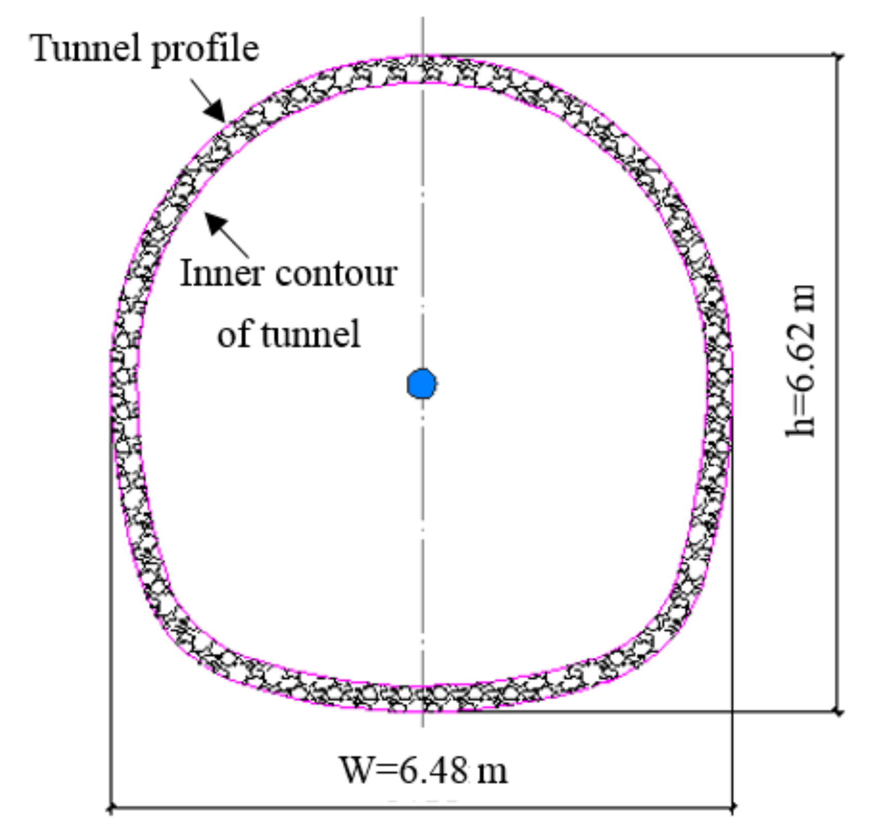
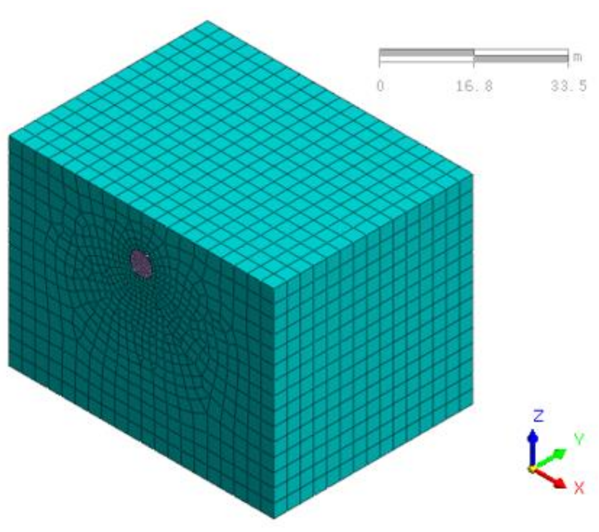
The stratum structure model was used to analyze the displacement mechanism of the surrounding rock during the full-face construction of a metro tunnel in a silty clay layer. The section size of a horseshoe-shaped subway tunnel is shown in Figure 2, with a width of 6.48 m and a height of 6.62 m. The initial support thickness was 25 cm, and the concrete grade was C20. Considering the disturbance effect of tunnel excavation with regard to surrounding rock, the calculation model used a value of 5 times the tunnel equivalent diameter, where the size was L * w * H = 60 * 80 * 60 m and the tunnel burial depth was 10 m. The calculation model is shown in Figure 3. In accordance with [19], the physical and mechanical parameters of silty clay are shown in Table 2, and the calculation parameters of the initial support are shown in Table 3.
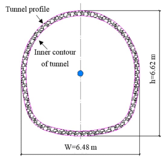
Figure 2.
A cross-section of the metro tunnel.

Figure 3.
Computational model.
Table 2.
Calculation parameters of the surrounding rock.
Table 3.
Calculation parameters of the initial support.
2.2. Calculation Condition
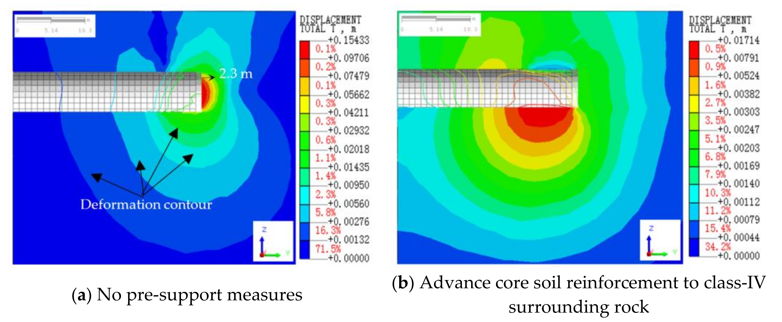
The tunnel was constructed using the full-face excavation method, where the excavation footage was 1 m at a time and the stress release rate of surrounding rock was assumed to be 0.8 and 0.2 in the next 2 construction steps. The above were the basic conditions of the numerical simulation, and then the variables of the 3 conditions were assumed, respectively. No pre-support measures were set for condition 1. For condition 2, the physical and mechanical parameters of the advanced core soil were increased to include grade-IV surrounding rock, and the longitudinal reinforcement length was 60 m. For condition 3, no pre-support measures were used, with changes made to the stress release rate of the surrounding rock only to analyze the influence of different initial support times on tunnel displacement. The simulated conditions are shown in Table 4.
Table 4.
Calculation conditions.
2.3. Analysis of Calculation Results
2.3.1. Influence Range of Full-Face Excavation
Figure 4a shows a simulated cloud picture of the surrounding rock displacement caused by full-face tunnel excavation without pre-support measures. It can be seen from the figure that the surrounding rock disturbance can be divided into the main area of influence and the secondary area of influence, with the displacement contour as the division index. The main area of influence (marked by crimson, red, deep yellow, and yellow) was located in front of the face, which was approximately hemispherical, with a radius of about 1.2–2.3 m. The secondary area of influence (marked by cyan, light blue and dark blue) gradually expanded from an ellipsoid shape to a horizontal “heart shape”, with the left tip and right area being concave and the upper and lower areas being convex. The shortest length of the concave influence area in front of the tunnel face was 6–9 m (about 1–1.5 times the tunnel diameter).

Figure 4.
Influence range of full-face tunnel excavation.
Figure 4b shows a simulation cloud picture of the surrounding rock displacement caused by tunnel full-face excavation when the core soil is reinforced to grade-IV surrounding rock. It can be seen from the figure that the main area of influence appears in the soil around the tunnel cavity behind the face, which is approximately hemispherical. The shape of the secondary area of influence becomes spherical and gradually diverges outward.
Through a comparison, it can be seen that the location and range of the surrounding rock influence zone caused by the full-face excavation are related to the strength of the advanced core soil. In other words, the extrusion displacement of the tunnel face and pre-convergence displacement are related to the strength of the advanced core soil. Whether it can be inferred that the strength of the advanced core soil affects or even determines the tunnel displacement (i.e., convergence displacement, pre-convergence displacement, and extrusion displacement of the tunnel face) will be discussed later.
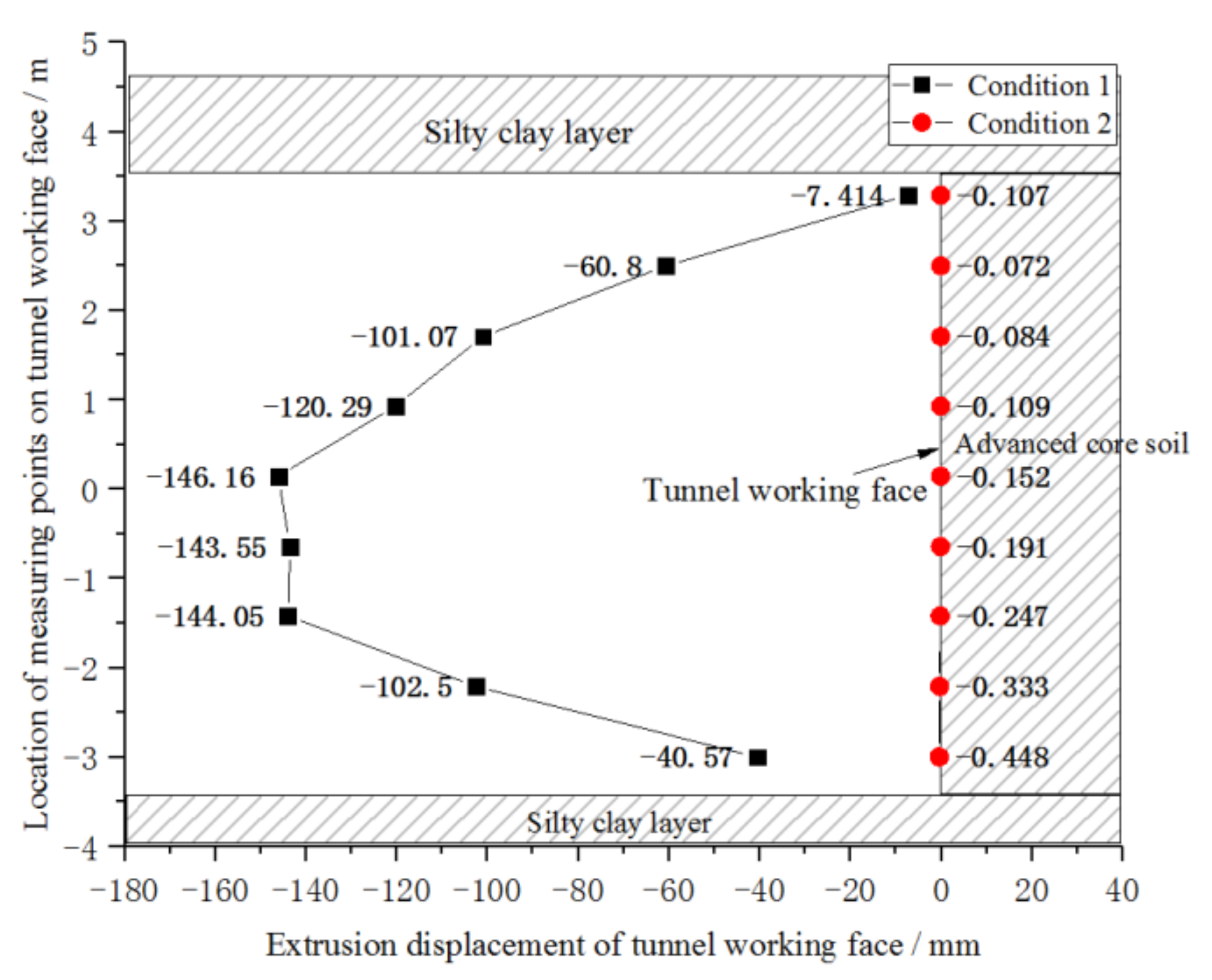
2.3.2. Extrusion Displacement of Tunnel Face
It can be seen from Figure 5 that the extrusion displacement curve of the tunnel face has an approximately “beer belly” shape without pre-support measures, and the maximum extrusion displacement is 146.16 mm, located at 1/2 H of the tunnel face. When the advanced core soil is reinforced by grade-IV surrounding rock, the displacement curve of the tunnel face is vertical and straight, and the displacement is negligible.
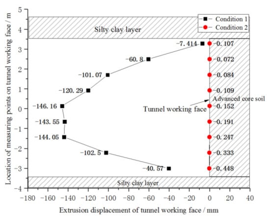
Figure 5.
Extrusion displacement of the tunnel face/mm.
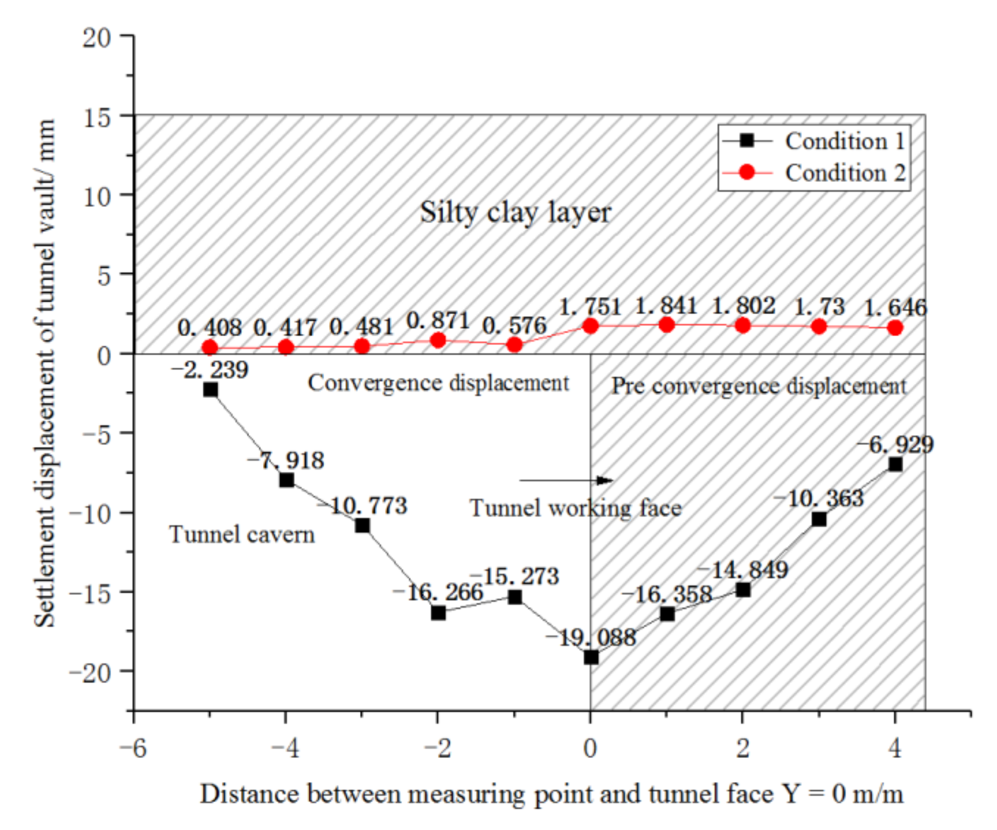
2.3.3. Settlement Displacement of the Tunnel Vault
It can be seen from Figure 6 that when there are no pre-support measures, the displacement of the tunnel vault presents a concave curve, and the maximum settlement value is at the tunnel face, which gradually converges to the tunnel chamber and the unearthed soil. When the advanced core soil is reinforced by grade-IV surrounding rock, the settlement curve is an approximately straight line, and there is only a slight settlement trend at the tunnel face. The pre-convergence displacement and convergence displacement can be ignored, and because the strength of the advanced core soil is too high, the tunnel vault appears to be uplifted.
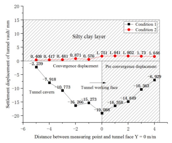
Figure 6.
Settlement displacement of the tunnel vault/mm.
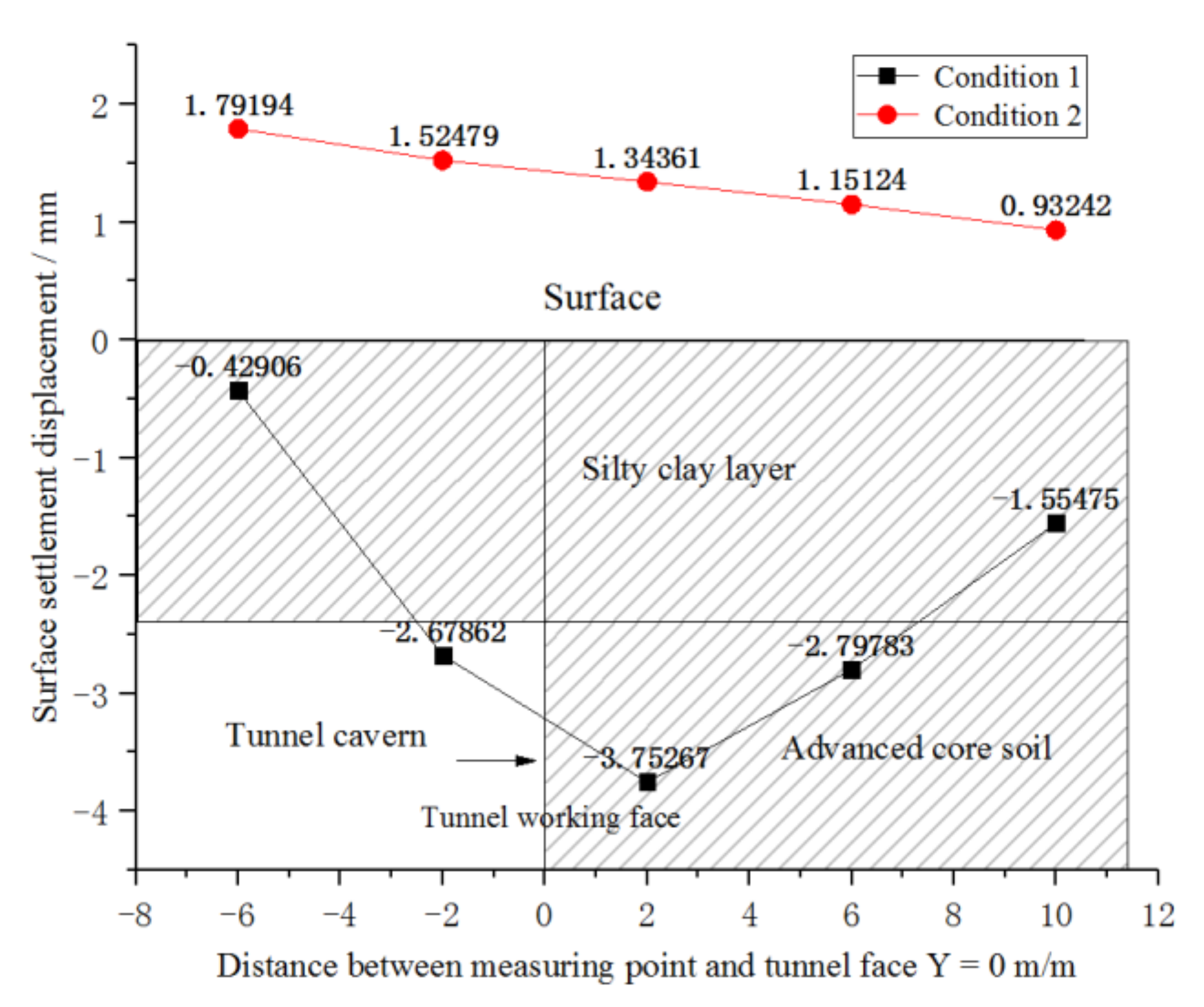
2.3.4. Surface Settlement Displacement
As can be seen from Figure 7, the surface displacement is similar to that of the tunnel vault. Without pre-support measures, the maximum settlement displacement occurs near the surface above the tunnel face. The results show that the convergence displacement and pre-convergence displacement were greatly reduced after the reinforcement of the advanced core soil, and surface uplift displacement occurred.

Figure 7.
Surface settlement displacement.
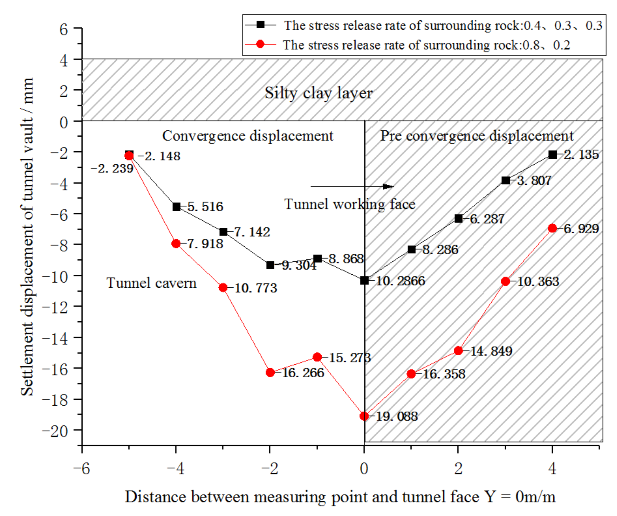
2.3.5. The Influence of Different Support Times on Tunnel Displacement
It can be seen from Figure 8 that the stress release rate of surrounding rock changed from 0.8 and 0.2 to 0.4, 0.3, and 0.3, the settlement displacement of tunnel face vault decreased by 85.6%, and the pre-convergence displacement decreased by 224.5%. Timely support can reduce the stress release rate of surrounding rock and the standing time of tunnel face soil, which are beneficial for reducing the settlement displacement and pre-convergence displacement of the tunnel face vault.
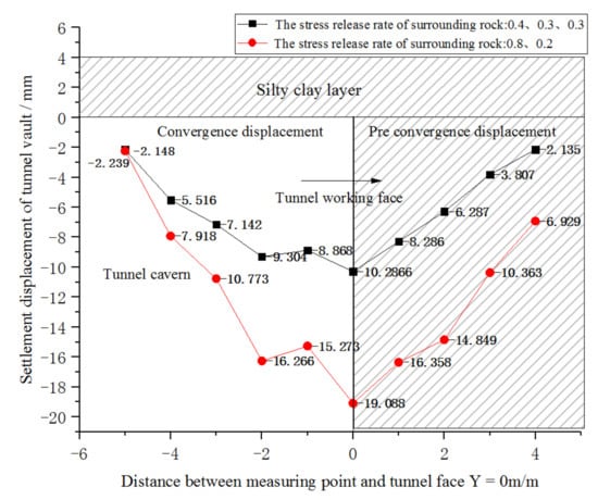
Figure 8.
Settlement displacement of the tunnel vault.
According to the above analysis, the following conclusions can be drawn:
- (1)
- Reinforcement of advanced core soil can reduce tunnel displacement (face extrusion displacement, pre-convergence, convergence) and surface displacement. The displacement of advanced core soil is the main cause of tunnel displacement. After excavation, extrusion displacement occurs in the advanced core soil, which leads to the pre-convergence of the tunnel, and the pre-convergence of the tunnel leads to a significant increase in the convergence displacement of the tunnel.
- (2)
- There are two ways to control the displacement of the advanced core soil: One is to employ pre-reinforcement measures (use of full section grouting, glass fiber anchors) to improve the physical and mechanical parameters. The second is to shorten the displacement time of the advanced core soil. Closing the initial support in time will reduce the exposure time of the tunnel face.
The following problems can also be further discussed:
- (1)
- The advanced core soil is composed of temporary surrounding rock, which is broken after maintaining a short period of stability. Therefore, the reinforcement of advanced core soil should not be too strong, as otherwise it will increase the construction energy consumption and reduce the construction efficiency. It is necessary to study the best construction parameters for pre-reinforcement measures.
- (2)
- Construction techniques for quick closing of the initial support.
3. Parameter Analysis of Advanced Core Soil Reinforced by Glass Fiber Anchors
The measures to reinforce the advanced core soil include the use of full-face grouting and glass fiber anchors. Full-face grouting is mainly used to improve the cohesion of the advanced core soil. This method is time-consuming and involves high costs.
Glass fiber anchors are a kind of material with tensile strength but no shear strength. They are bonded to the surrounding soil by grouting and restrict the extrusion displacement of the core soil with their own tensile strength. Zhang [20] reported that glass fiber anchors effectively improved the overall strength of the core soil to be excavated in front of the tunnel face and reduced tunnel displacement. This method was applied in the Liu Yanghe railway tunnel. This section further analyzes the construction parameters (such as density, longitudinal reinforcement length, and lap length) of advanced core soil reinforced by glass fiber anchors.
3.1. Reinforcement Density of the Tunnel Face
In order to determine the reasonable density of tunnel faces strengthened by glass fiber anchors, the pull-out force and reinforcement range of a single glass fiber anchor should be analyzed.
3.1.1. Experiment on the Strengthening Effect of the Glass Fiber Anchor
We carried out the test near the First-Phase Project Department of the Pipe Gallery at the Lucheng Metro Station in Tongzhou District, Beijing. The test site has multi-year pile soil, where the soil is silt, the soil cohesion is 15 kPa, the friction angle is 13°, the water content is 10~15%, and the dry density is 1.4~1.7 g/cm3.
- (1)
- Purpose of the experiment
The reinforcement effect of glass fiber anchor on silty clay with different grout and density values was tested.
- (2)
- Test materials and parameters
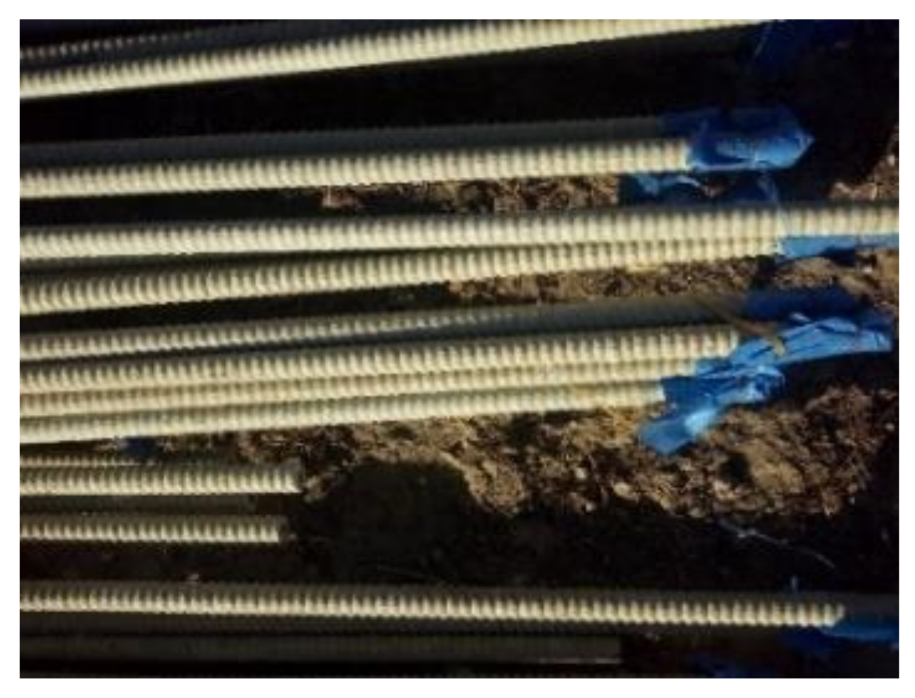
Test consumables: glass fiber anchor, anchor tension meter (measuring range 500 kN, accuracy 0.01 kN), cement slurry, cement slurry + water glass, etc. Table 5 shows the parameters of the glass fiber anchor for the test, and Figure 9 shows the parameters of the glass fiber anchor for the test.
Table 5.
Parameters of the glass fiber anchor.

Figure 9.
Glass fiber anchor.
- (3)
- Comparative experimental design
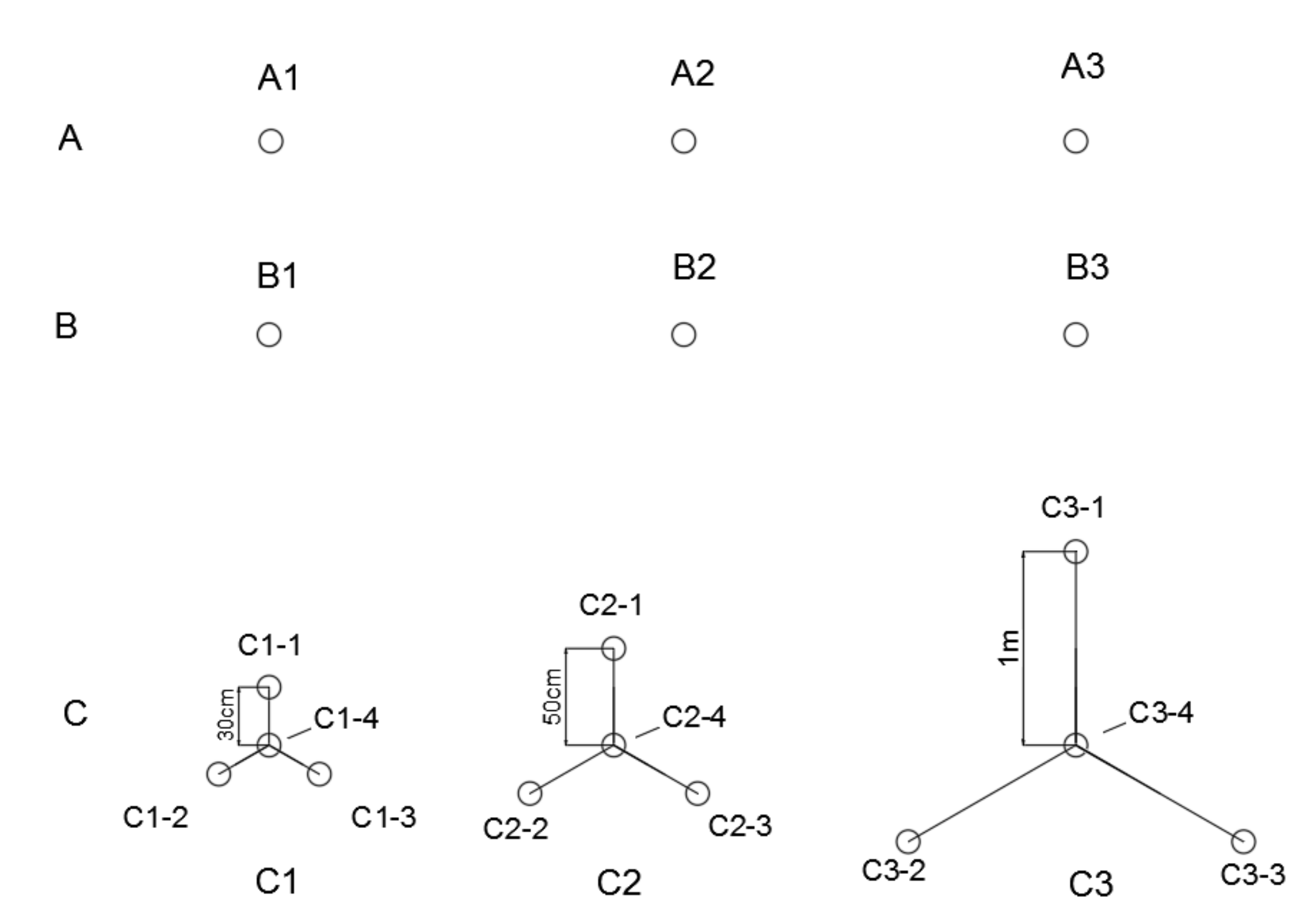
Group A: Slurry was injected, and 3 glass fiber anchors were drilled: A1, A2, and A3.
Group B: Double liquid slurry was injected, and 3 glass fiber anchors were drilled: B1, B2, and B3.
Group C: Double liquid slurry was injected, and 3 groups of glass fiber anchors were drilled: C1, C2, and C3. These had different densities. See Figure 10.
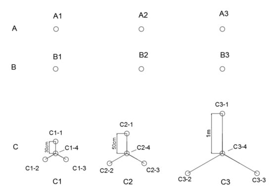
Figure 10.
Drilling layout of glass fiber anchors.
- (4)
- Test process is shown in Figure 11.
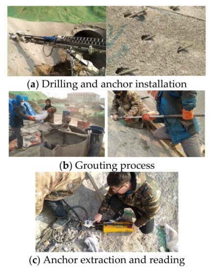 Figure 11. Test process.
 - (5)
- Analysis of test results
It can be concluded from Table 6 that the pull-out force of a single glass fiber anchor was about 25.42 kN when single slurry grouting was used for reinforcement, but the single slurry was not able to solidify in time during the test. When grouting with double slurry, the pulling resistance of single glass fiber anchor was about 31.58 kN. According to the test data of group C, when the distance between glass fiber anchors was 30 cm, the average pull-out force of a single glass fiber anchor was about 41.55 kN. When the distance between the glass fiber anchors was 50 cm, the average pull-out force of a single glass fiber anchor was about 38.47 kN. When the distance between glass fiber anchors was 1 m, the average pull-out force of a single glass fiber anchor was about 30.91 kN.
Table 6.
Test results of the pull-out resistance of glass fiber anchors.
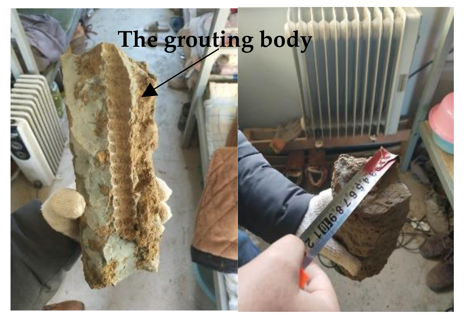
When the installation spacing was less than 1 m, the pull-out force of the glass fiber anchor appeared to couple with the amplification effect. The end grouting method was adopted for the glass fiber anchor rod. The diffusion radius of slurry in silty clay was 7 cm, as measured from the grouting body obtained after excavation (Figure 12).

Figure 12.
Glass fiber bolt grouting body.
3.1.2. Numerical Calculation of the Installation Density of the Glass Fiber Anchor
The model and tunnel structure dimensions are shown in Figure 2 and Figure 3. The parameters in Table 2 and Table 3 were used for the calculation of the surrounding rock and initial support. Full-face excavation was carried out; the excavation footage was 1 m at a time, and the stress release rate values of the surrounding rock were set as 0.8 and 0.2. According to the calculation results in Figure 4, the influence range of full-face excavation on the soil in front of the tunnel face was 1–1.5 times the tunnel diameter, and the radius of the main influence area was about 1–1.4 m. It was assumed that the longitudinal reinforcement length of glass fiber anchor was 2 times the tunnel diameter (i.e., 12 m), and the lap length was 1 m. The simulated conditions are shown in Table 7.
Table 7.
Simulated calculation conditions.
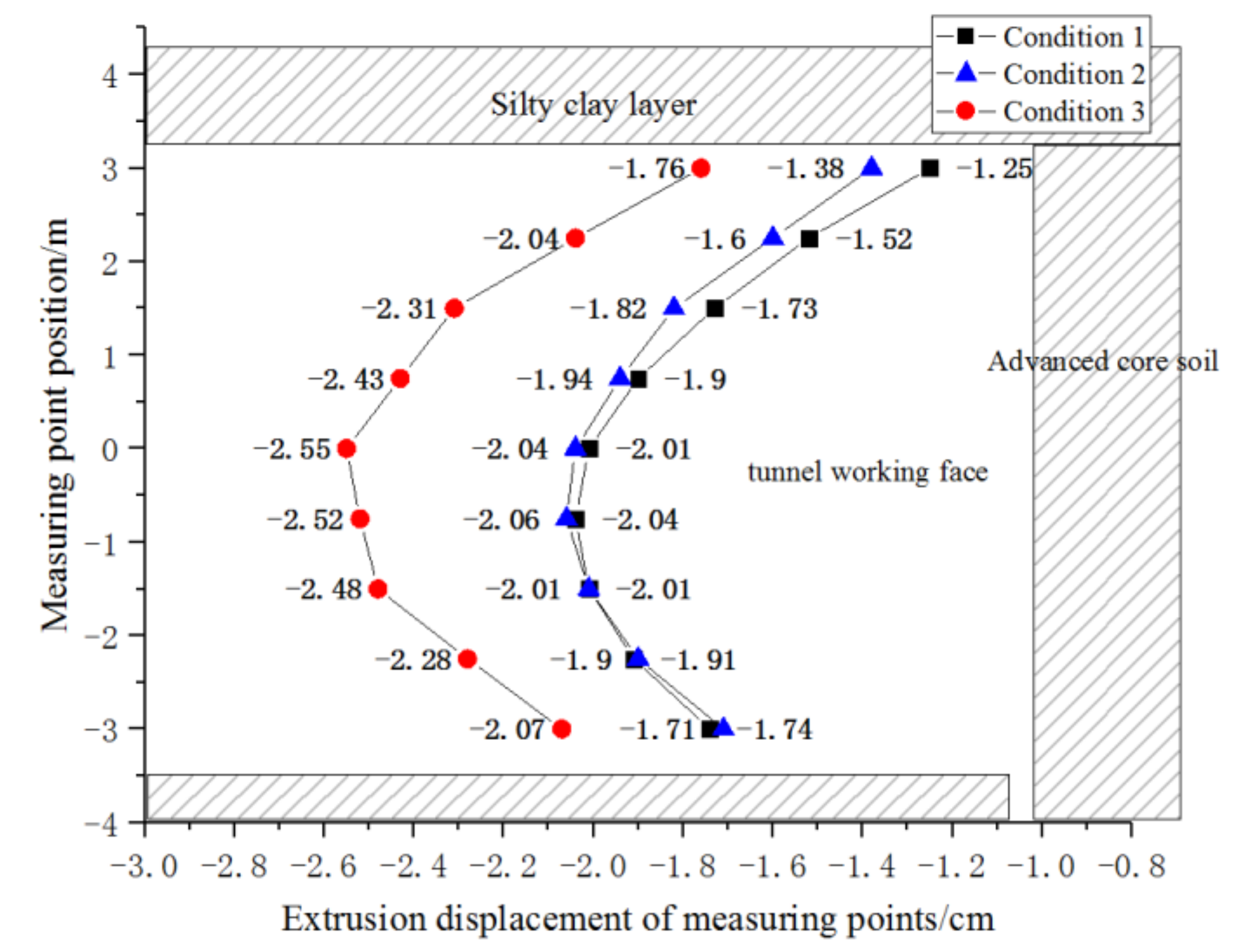
According to the research conclusions in Section 2.3, the strength of advanced core soil determines the tunnel displacement; that is, the extrusion displacement of the tunnel face determines the pre-convergence displacement, convergence displacement, and surface displacement. Therefore, the extrusion displacement of tunnel face under 3 working conditions is analyzed below. As shown in Figure 13.
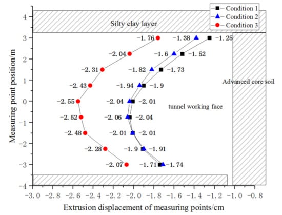
Figure 13.
Extrusion displacement of the tunnel face under 3 conditions.
Compared with no pre-support measures (Figure 5), the maximum extrusion displacement of tunnel face in condition 1 was reduced by 6/7. It can be seen that the glass fiber anchor with a reinforcement density of 1.0 × 1.0 m played a great role in controlling the extrusion displacement of the tunnel face. Comparing the displacement curves of condition 2 and condition 1, it can be seen that changing the reinforcement density of the upper half section had no obvious effect on the extrusion displacement of the tunnel face. Compared with condition 1, the installation density of glass fiber anchor rod in condition 3 increased from 1.0 × 1.0 m to 1.5 × 1.5 m, and the extrusion displacement of the tunnel face obviously increased, with the maximum value of 2.55 cm (increase of 25%). From the comparison of the three curves, it can be concluded that the extrusion displacement of the tunnel face mainly occurred in the middle and lower sections (about 1/3 of the distance from the vault). Strengthening the middle and lower sections can effectively restrict the extrusion displacement. It is reasonable to choose an upper sparse and lower dense reinforcement method, which may not only reduce the material cost but also shorten the reinforcement time of the tunnel face.
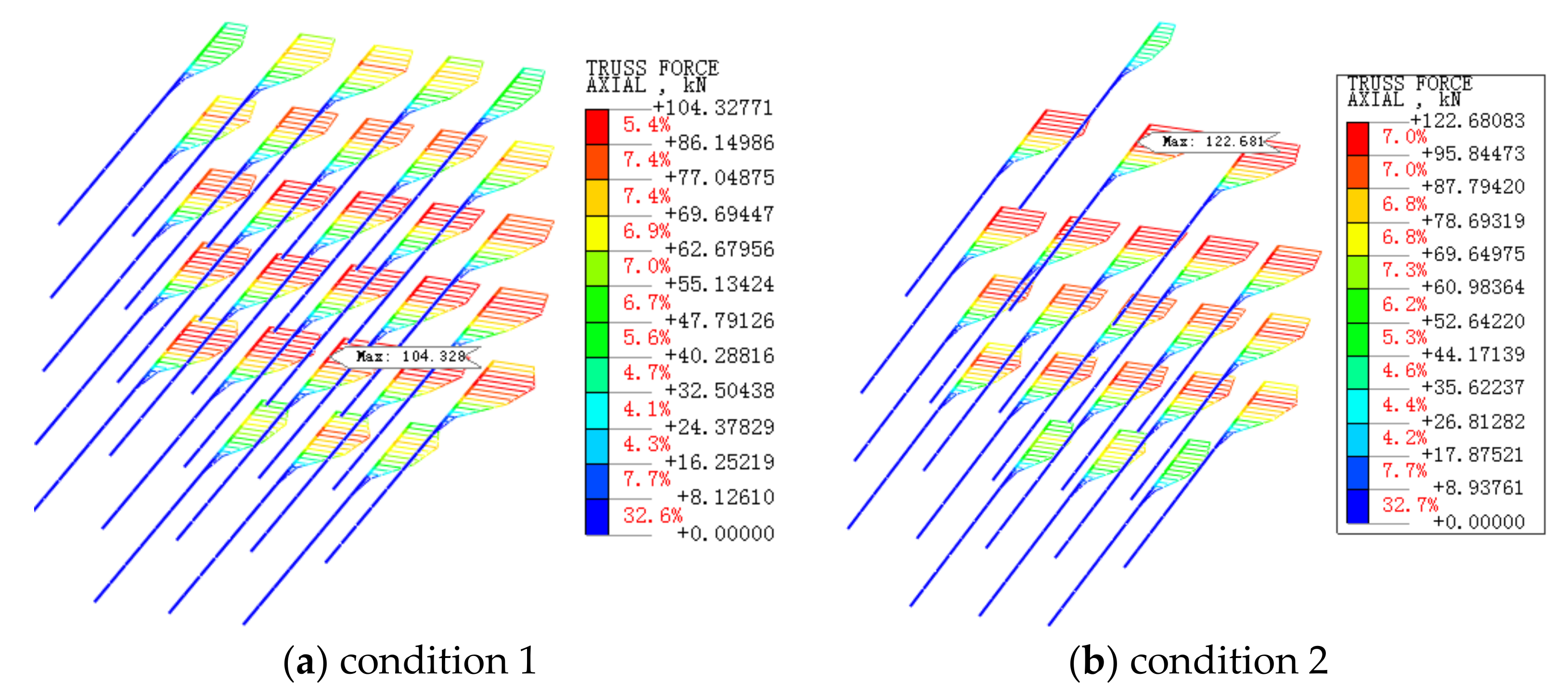
Two conditions are shown in Figure 14, which presents an axial force diagram of the remaining 2 m of the reinforcement length of the glass fiber anchor. The maximum axial force of the glass fiber anchor in condition 1 was 104.328 kN, located in the lower half of the section. In condition 2, the maximum axial force of the glass fiber anchor was 122.681, kN, located in the upper half of the section. This was due to the increase in reinforcement density, which led to the relative increase in the axial force of the single glass fiber anchor. According to the axial force, the specification of the glass fiber anchor can be chosen or new reinforcement materials with tensile strength but no shear strength can be developed.
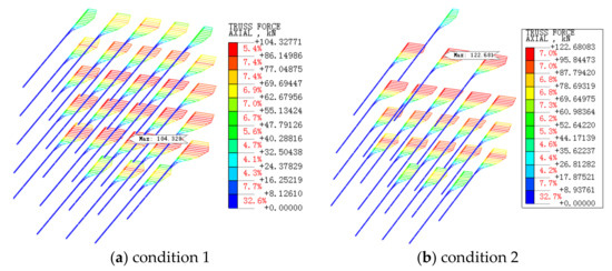
Figure 14.
Axial force of glass fiber anchor/kN.
3.2. Longitudinal Reinforcement Length and Lap Length of the Glass Fiber Anchor
The longitudinal reinforcement length of the glass fiber anchor can be determined according to the influence range of full-face excavation on soft soil. According to the analysis results of Figure 4 in Section 2.3.1, it can be set to 2–3 times of the equivalent excavation diameter. Next, we need to study how many meters are left in the length of glass fiber anchor, and we need to perform the next ring of glass fiber anchor pre-reinforcement construction. The calculation model of condition 2 in Section 3.1.2 was adopted for the numerical calculations, and 4 analysis conditions were set, as shown in Table 8.
Table 8.
Simulated calculation conditions.
It can be seen from Figure 15 that compared with condition 3, the remaining length of glass fiber anchor rod in condition 4 was increased by 0.5 m, but the extrusion displacement of the tunnel face would be slightly reduced. The maximum value would change from 2.74 cm to 2.68 cm (a reduction of 2.19%), and the reinforcement effect was not obvious. Compared with condition 3, the remaining length of the glass fiber anchor rod in condition 2 decreased by 0.5 m, and the extrusion displacement of tunnel face clearly increased, with the maximum value changing from 2.74 cm to 3.77 cm (an increase of 37.6%). Compared with condition 3, the remaining length of glass fiber anchor rod in condition 1 decreased by 1.0 m, and the extrusion displacement of tunnel face increased sharply, with the maximum value changing from 2.74 cm to 6.95 cm (an increase of 153.6%). Through the analysis, it is suggested that the lap length of the glass fiber anchor should be the radius of the main area of influence in front of the tunnel face.
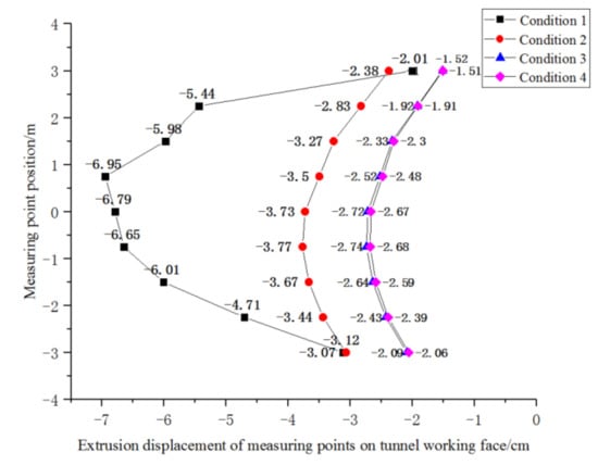
Figure 15.
Extrusion displacement of the face under 4 working conditions.
4. Rapid Closure Technology of the Initial Support
There are two ways to achieve rapid closure of the initial support. One is to transform the traditional initial support construction technology. By changing the mix proportion of shotcrete and developing new admixtures and accelerators, the early strength of shotcrete can be brought into full play in time. It can thus bear the load together with the grid arch and restrict the displacement of surrounding rock.
The second method is to use a fabricated initial support instead of the traditional initial support, for example using a fabricated corrugated steel plate + back grouting, a fabricated steel truss, etc. This can facilitate the rapid assembly and early closure of the initial support, change the line support of the steel grid into the face support of the corrugated steel plate, and provide the surrounding rock with support as soon as possible. At present, the feasibility testing of prefabricated corrugated steel initial support is being carried out in the test site of the Pipe Gallery Project Department of Lucheng Metro Station in Tongzhou District, Beijing, and preliminary success has been achieved, as shown in Figure 16. In the future, we will further research the bearing mechanism, joint type, stress, and joint waterproof characteristics of corrugated steel primary supports.
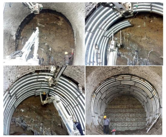
Figure 16.
Assembly process of corrugated steel.
5. Conclusions
Based on the mechanized full-face construction of a metro tunnel, this paper studies the displacement law and supporting mechanism of a tunnel face in a mainly silty clay layer. The conclusions are as follows:
- (1)
- The influence of full-face excavation of a metro tunnel on surrounding rock can be categorized with regard to the hemispherical main area of influence and the transverse “heart” secondary area of influence, in which the radius of the main area of influence was 1.2–2.3 m. These values can be used as a reference with regard to the lap radius of the advanced reinforcement material on the tunnel face. The shortest influence range of the “heart” secondary area of influence was 6–9 m (about 1–1.5 times of the tunnel diameter) in front of the tunnel face.
- (2)
- The displacement of advanced core soil is the main cause of tunnel displacement. By increasing the strength of advanced core soil (E, C, Φ) or reducing the displacement time of the tunnel face, the tunnel displacement and surface displacement can be greatly reduced. For example, if the stress release rate of surrounding rock changes from 0.8 and 0.2 to 0.4, 0.3, and 0.3, the settlement displacement of the vault can be reduced by 85.6%, and the pre-convergence displacement can be reduced by 224.5%.
- (3)
- The test results showed that a glass fiber anchor rod injected with double slurry can lead to cylindrical reinforcement with a diameter of 14 cm in silty clay. The pull-out force of a single glass fiber anchor is about 31.58 kN. When the installation spacing is less than 1 m, the pull-out force of glass fiber anchor will appear, and couples with the amplification effect.
- (4)
- When using glass fiber anchors to reinforce the advanced core soil, it is more reasonable to choose the upper sparse and lower dense reinforcement method (where the reinforcement density of the upper-half section is 1.5 × 1.5 m and the reinforcement density of the lower-half section is 1.0 × 1.0 m). This can not only reduce the material cost, but also shorten the construction time of the reinforcement tunnel face.
- (5)
- The use of prefabricated initial supports represents a development trend in tunnel support construction technology in the future. This type of support can quickly be closed to provide support resistance, and the bearing mode is thus changed from line support to face support.
Author Contributions
Conceptualization, M.H. and Z.Z.; data curation, C.Y.; funding acquisition, M.H.; investigation, Z.Z.; software, Z.Z.; supervision, M.H.; validation, X.F.; writing—original draft, Z.Z.; writing—review and editing, Z.Z. All authors have read and agreed to the published version of the manuscript.
Funding
The authors acknowledge the financial support provided by General project of national natural fund of China (51878037) and the National key R & D program funding (2018YFC0808705).
Institutional Review Board Statement
Not applicable.
Informed Consent Statement
Not applicable.
Data Availability Statement
Not applicable.
Conflicts of Interest
The authors declare no conflict of interest.
References
- Wang, M.S. Construction method of shallow buried excavation in Beijing Metro. Chin. J. Rock Mech. Eng. 1989, 1, 52–62. [Google Scholar]
- Tan, Z.S. Construction concepts and key technologies for tunnel and underground engineering—A celebration of main academic thoughts and achievements of Academician WANG Mengshu. Hazard Control Tunn. Undergr. Eng. 2019, 1, 1–6. [Google Scholar]
- Lunardi, P.; Barla, G. Full face excavation in difficult ground. Geomech. Tunn. 2014, 7. [Google Scholar] [CrossRef]
- Lunardi, P. Evolution of Design and Construction Approaches in the Field of Tunnelling: The Results of Applying ADECO-RS When Constructing Large Underground Works in Urban Areas. Procedia Eng. 2016, 165. [Google Scholar] [CrossRef]
- Prisco, C.; Flessati, L.; Frigerio, G.; Castellanza, R.; Caruso, M.; Galli, A.; Lunardi, P. Experimental investigation of the time-dependent response of unreinforced and reinforced tunnel faces in cohesive soils. Acta Geotech. 2018, 13. [Google Scholar] [CrossRef]
- Horn, M. Horizontaler Erddruck auf senkrechte Abschlussflahen von Tunneln. In Landeskonferenz der Ungarischen Tiefbauindustrie; Deutsche überarbeitung STUVA: Düsseldorf, Germany, 1961. [Google Scholar]
- Jancsecz, S.; Steiner, W. Face support for a large mix-shield in heterogeneous ground conditions. In Tunnelling’94; Springer: Boston, MA, USA, 1994; pp. 531–550. [Google Scholar]
- Li, H.Y. Stability analysis of shallow tunnel face under pure clay condition. J. Rail. Sci. Eng. 2020, 17, 3150–3156. [Google Scholar]
- Chen, Z.; He, P.; Yan, D.M.; Gao, H.J.; Nie, A.X. Upper limit analysis of stability limit of tunnel face under advanced support. Rock Soil Mech. 2019, 40, 2154–2162. [Google Scholar]
- An, Y.L.; Li, J.H.; Cao, Q.; Yue, J. Influence of footage on stability of tunnel face based on limit analysis. J. Rai. Sci. Eng. 2019, 16, 443–449. [Google Scholar]
- Du, J.; Mei, Z.R.; Fu, L.L.; Chen, Y.C. Study on face stability of shallow tunnel with weak surrounding rock based on strength reduction method. Mod. Tunn. Technol. 2020, 57, 51–57. [Google Scholar]
- Wang, X.Y.; Li, K.; Wang, L.J.; Zheng, W.H.; Wang, X.D. Study on limit support pressure of tunnel face in soft surrounding rock. J. China Rail. Soc. 2019, 41, 110–117. [Google Scholar]
- Duan, L.Y. Study on Displacement Law of New Tunnel Passing through Existing Subway Structure in Beijing Area. Master’s Thesis, Beijing Jiaotong University, Beijing, China, 2017. [Google Scholar]
- Zhao, K. Study on Optimization of Metro Station and Bridge Crossing Scheme. Master’s Thesis, Beijing Jianzhu University, Beijing, China, 2018. [Google Scholar]
- Ke, C.J. Analysis on Displacement Characteristics of Urban Tunnel Undercrossing Existing Lines with Different Structures. Master’s Thesis, Beijing Jiaotong University, Beijing, China, 2018. [Google Scholar]
- Tao, L.J.; Tian, Z.W.; Che, Y.W.; Chen, X. Micro displacement control technology of mining method tunnel under existing shield tunnel. Rail. Eng. 2017, 5, 67–70. [Google Scholar]
- Yang, Z.-Y.; Jiang, Y.S.; Yan, Z.G. Analysis on Settlement Law of shield tunneling under metro operation. J. Xi’an Univ. Sci. Technol. 2014, 34, 268–273. [Google Scholar]
- Wang, S.M. Study on Risk Control Measures for Shield Tunneling under Existing Subway in Beijing. Master’s Thesis, Beijing Jiaotong University, Beijing, China, 2014. [Google Scholar]
- Hou, G.Y.; Liu, H.Y.; Li, J.J.; Gao, R.Z.; Wang, Q.; Zhang, M.D. Numerical analysis of subway tunnel construction process based on excavation unloading effect. J. Rock Mech. Eng. 2013, 32, 2915–2924. [Google Scholar]
- Zhang, J.W.; Mei, Z.R. Study on strengthening mechanism of tunnel face strengthened by fully bonded bolt. Tunn. Constr. 2010, 30, 161–165. [Google Scholar]


Publisher’s Note: MDPI stays neutral with regard to jurisdictional claims in published maps and institutional affiliations. |
© 2021 by the authors. Licensee MDPI, Basel, Switzerland. This article is an open access article distributed under the terms and conditions of the Creative Commons Attribution (CC BY) license (https://creativecommons.org/licenses/by/4.0/).