Abstract
Integrated gate commutated thyristors (IGCTs) are critical components in high-voltage, high-current, and high-power conversion systems, particularly in offshore wind energy systems. However, the working environment of offshore wind energy conversion systems is extremely harsh. In this article, we propose an active damage control approach aiming at enhancing the reliability of the conversion system. By employing electro-thermal modeling for the equipment of the offshore wind energy conversion system, the junction temperature and fatigue damage of IGCT are simulated during the operation process. Using the improved model predictive current control (MPCC) method, active damage control effectively regulates the switching frequency of IGCT. IGCTs are symmetrically distributed on each leg of the converter, so the lifespan of the two IGCTs on each leg is also considered to be similar. This method balances the life of the IGCTs on the three legs of the converter and optimizes their utilization to the maximum extent. These measures effectively enhance the reliability of the conversion system and lower the operation and maintenance cost of high-power IGCT converters. The effectiveness of the proposed method is validated by co-simulation results by ANSYS and MATLAB/Simulink.
1. Introduction
With the rapid development of offshore wind power technology, there has been a growing demand for high-power devices capable of meeting the system’s expanding requirements. Traditional insulated gate bipolar transistors (IGBTs), as critical components of wind power converters, cannot satisfy the increasing demands for high-voltage, high-current, and high-power offshore wind power conversion systems. As a result, high-power devices like integrated gate commutated thyristors (IGCTs), particularly those with blocking voltages exceeding 4500 V, have been increasingly popularized and applied. IGCTs are fully controlled semiconductor switching devices that evolved from traditional GTOs with the implementation of hard-switching technology. They combine the power advantages of GTOs with the high-frequency advantages of IGBTs, making them the largest fully-controlled power devices in use [1,2,3,4].
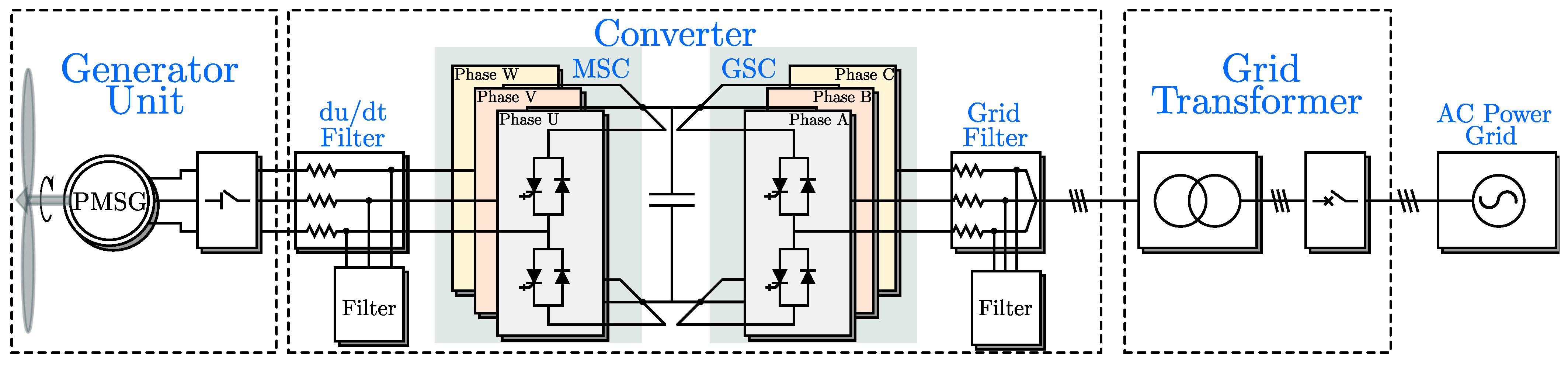
The wind energy conversion system has a symmetric back-to-back configuration. The structural diagram of the wind energy system is illustrated in Figure 1. The machine side converter (MSC) is connected to the generator stator to achieve variable speed and constant frequency control. This facilitates optimal power generation efficiency and transfers power to the grid side converter (GSC) through the DC-link, which consists of a DC-link capacitor used to balance the instantaneous power difference between MSC and GSC and minimize voltage and current fluctuation. GSC is connected to the AC power grid to provide high-quality power while balancing the voltages on both sides of the DC link.
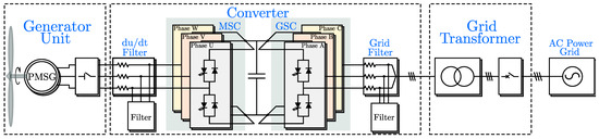
Figure 1.
Structural diagram of the wind power system.
However, offshore wind power systems operate in a very harsh environment, resulting in a high failure rate of units and converters. Due to drastic fluctuations in wind power, wind power converters experience significant changes in electrical and thermal stresses, posing threats to their safety and reliability. Moreover, the high concentration of salt spray, along with high humidity and frequent severe weather conditions in distant sea areas, profoundly impacts the safe operation of electrical equipment [5]. Power components in wind power converters have a failure rate of more than 30%, which accounts for the highest failure rate [6]. In addition, offshore wind turbines have poor accessibility and are difficult regarding operation and maintenance (O&M). Therefore, it is necessary to study the predictive maintenance technology of converter power devices to enhance the operation reliability of converters.
Innovations in offshore wind energy O&M include changes in practices, optimization of strategies, improvement of equipment, and enhancement of fault diagnosis and monitoring technologies. The smartification of the lifecycle of offshore wind energy systems is the key to realizing the optimal levelized cost of energy (LCOE) and enhancing the reliability of offshore wind energy systems. In this article, we propose a new approach to optimize the through-life of the IGCT based on the life prediction method and model predictive current control (MPCC).
The traditional life prediction method offers an approach to predict the service life of IGCT based on its junction temperature changes [7,8,9]. These methods allow for the replacement of the IGCT before it fails, thus reducing the converter’s failure rate and the downtime of the converter. However, it does not maximize the utilization of the IGCT. Therefore, this method does not effectively reduce O&M costs. Moreover, IGCTs operating at high temperatures for extended periods, accompanied by violent temperature fluctuations, also increase the harmonic distortion rate of the converter system’s output current, leading to a degradation in power quality.
Lifetime optimization control of the converter based on junction temperature can effectively reduce the mean junction temperature and junction temperature fluctuation of IGCT, thereby improving the lifespan of IGCT to a certain extent. There are several main types of common junction temperature control methods, as shown in Table 1.

Table 1.
Main types of common junction temperature control methods.
Recent studies have proposed methods to reduce the junction temperature of IGBTs by controlling power losses and fatigue damage based on MPC [14,15]. These methods essentially reduce the junction temperature by adjusting the switching frequency. By taking power losses or accumulated fatigue damage into the MPC, these methods effectively reduce the junction temperature and extend the converter’s lifespan.
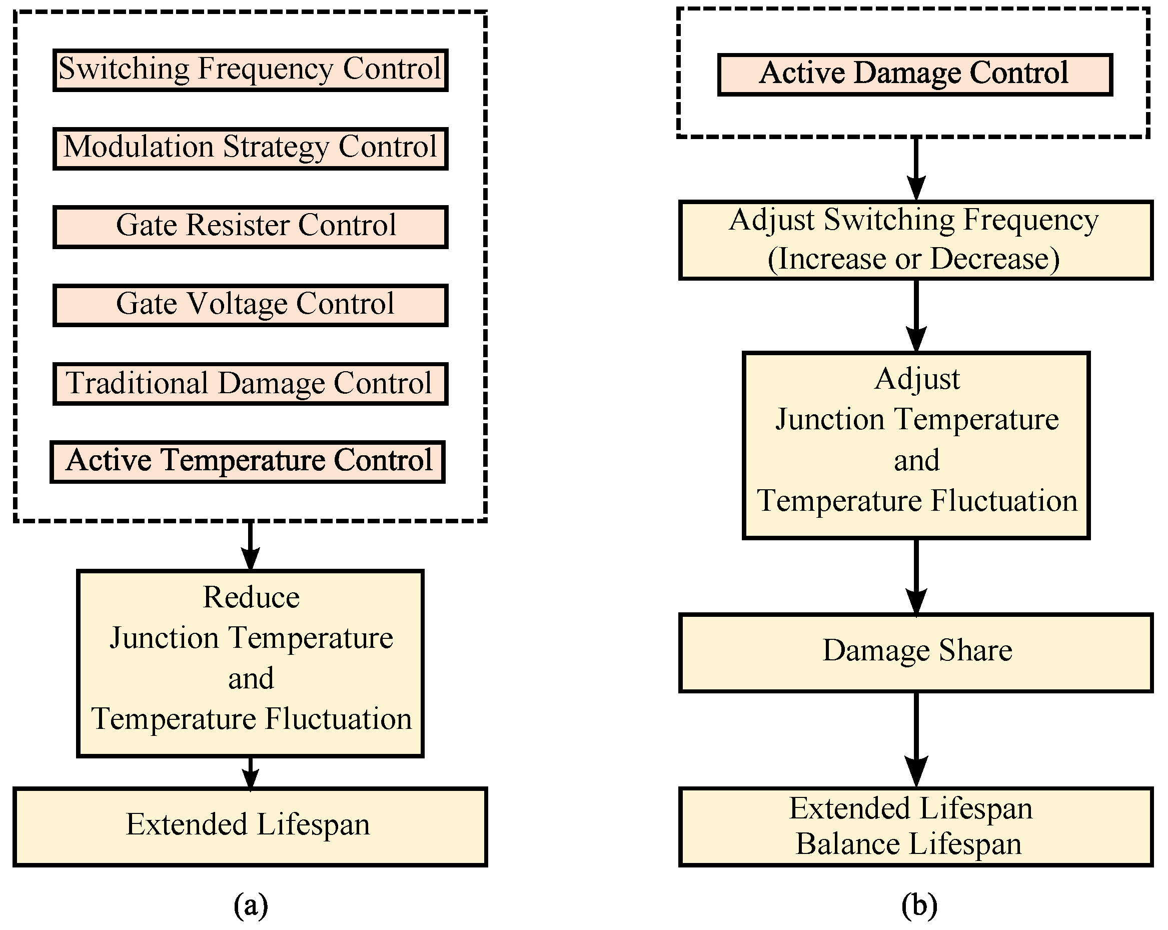
Having argued all the above approaches and compared them, as shown in Figure 2, we found that they effectively extend the lifespan of IGCT to a certain extent. However, a complete converter has at least three pairs of IGCTs, and their remaining lifespans are generally different. In this case, these IGCTs can not maximize their utilization because they are replaced one by one when they are broken. This leads to inevitable waste.

Figure 2.
Comparison of traditional lifetime optimization control and active damage control. (a) Traditional lifetime optimization control. (b) Active damage control.
On this basis, this paper analyzes and calculates the cumulative fatigue damage of the IGCT. To actively control the junction temperature and cumulative fatigue damage differences of IGCTs, the model predictive current control (MPCC) method, which minimizes the cost function related to both the cumulative fatigue damage and the output current, is improved. The proposed control approach effectively reduces the mean junction temperature and junction temperature fluctuation of IGCT by adjusting its switching frequency. This, in turn, reduces the cumulative fatigue damage differences among the IGCTs on the three legs of the converter, thereby balancing their service life. In other words, the relatively new IGCT divides its extra lifetime evenly among the other IGCTs, which is called damage share, as shown in Figure 2. Additionally, the replacement frequency of IGCT and the downtime of the converter are reduced, effectively enhancing reliability and reducing the O&M costs of high-power IGCT converters.
The contents of this article are organized as follows. In Section 2, the characteristics of IGCT and its failure mechanism are presented. Section 3 presents the conversion system and the fatigue damage calculation system. Section 4 describes the optimization and control strategy and then conducts simulation experiments. Section 5 analyzes the simulation results, and Section 6 concludes the paper.
2. The Characteristics of IGCT
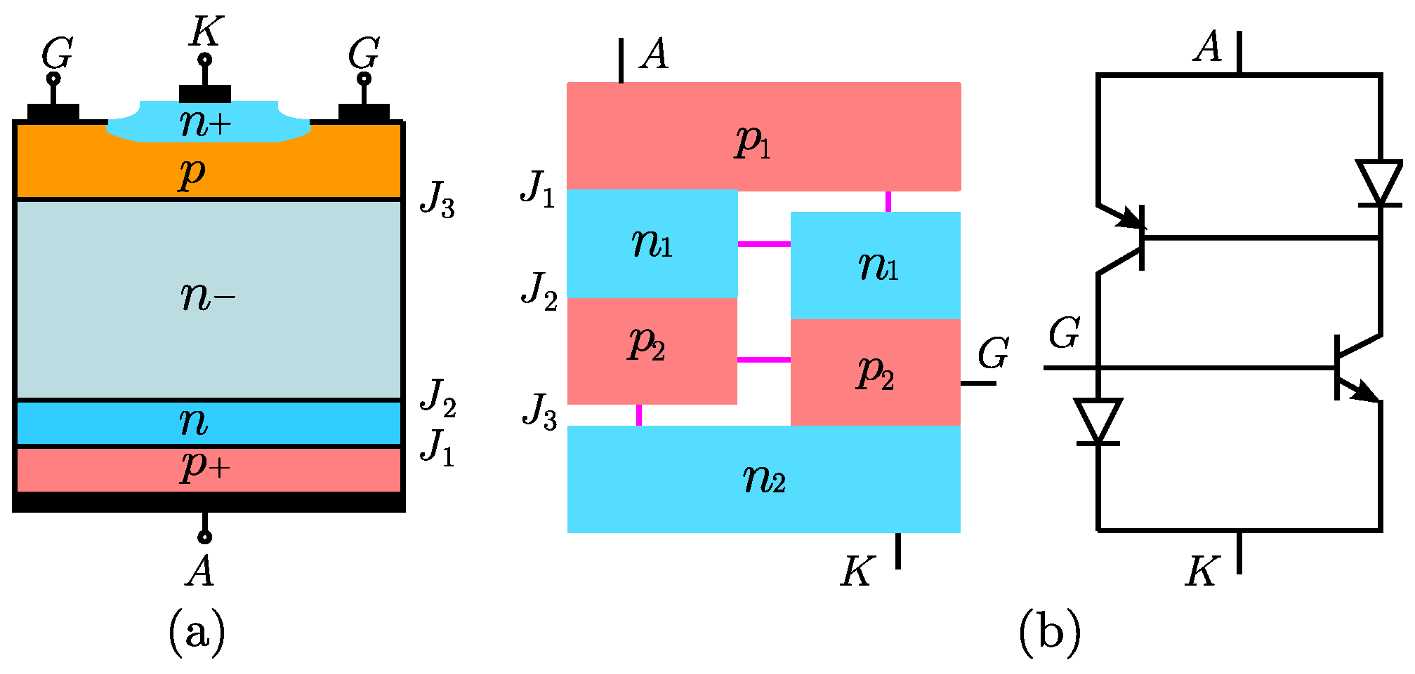
IGCTs are used as fully controlled semiconductor devices in high-power converters. Their equivalent structure is illustrated in Figure 3. As illustrated in Figure 3a, , , and are three p–n junctions formed within the five-layer structure of IGCT, as shown in Table 2. The cathode surface structure of the IGCT can be visualized as several GCT units surrounding each other, along with gate electrodes. Each unit can be considered equivalent to a PNP and NPN transistor pair, as illustrated in Figure 3b. The operating state of IGCT can be described using a thyristor model and a pair of transistors connected in parallel [16,17].

Figure 3.
Equivalent structure of the IGCT circuit. (a) IGCT section structure. (b) IGCT equivalent model.
Table 2.
Five layer structure of IGCT.
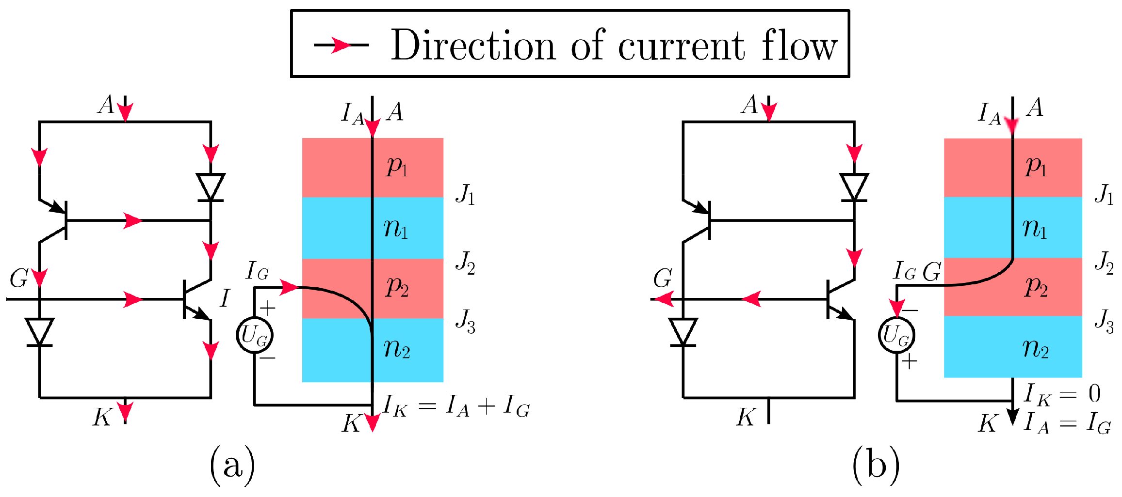
There are two operating states for the IGCT during operation: on-state and off-state. In the on-state, as illustrated in Figure 4a, the IGCT gate triggers a super-strong current pulse, causing the transistors to couple together to form a positive feedback channel for the current. Within the semiconductor structure, , , and junctions are in the forward bias, where the Webster effect occurs between the p-layer and the n-layer. This causes the IGCT to behave equivalently to a high-power diode in the on-state.
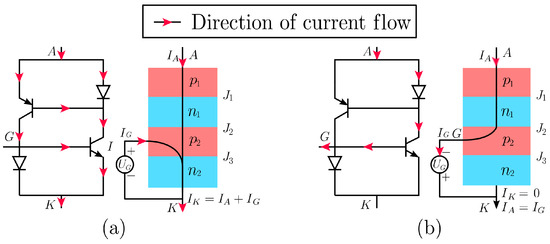
Figure 4.
Equivalent circuit principle of IGCT. (a) IGCT on-state. (b) IGCT off-state.
In the off-state, as illustrated in Figure 4b, the junction rapidly expands to form a wide depletion layer. The cathode current rapidly drops to 0, while the anode current briefly passes through the gate, generating a strong off-pulse current. With the addition of positive cathode voltage, and become forward-biased within the semiconductor structure. Meanwhile, carries the reverse bias voltage, causing the IGCT to behave equivalently to a high-power diode in an off-state.
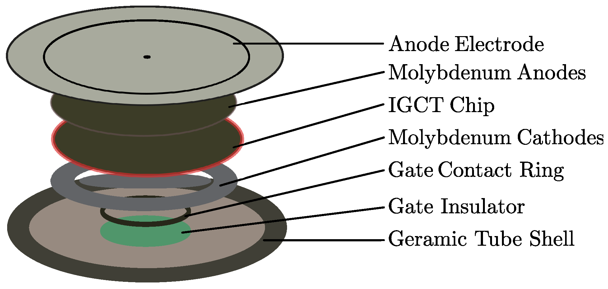
The IGCT module, illustrated in Figure 5, is a pressure contact device that differs significantly in structure from the traditional welded IGBT module. It addresses the failure mode of wire bonding found in welded modules. These components rely on pressure to prevent rigid connections between layers with different coefficients of thermal expansion. However, pressure contact modules lack dielectric isolation, and issues such as uneven pressure distribution and spring relaxation pose reliability challenges that are distinct from those of welded modules. During operation, the IGCT undergoes continuous thermal cycling. As a result, varying degrees of fatigue damage can occur in the IGCT due to thermal stress. This article mainly focuses on the study of component deformation caused by thermal stress [18,19,20,21,22].
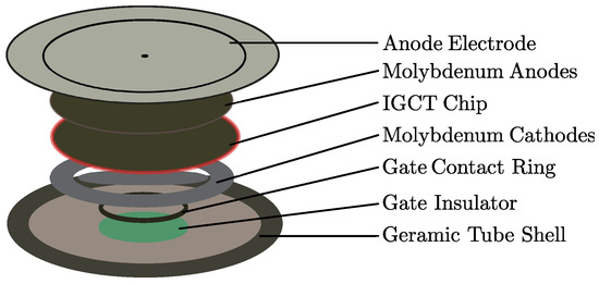
Figure 5.
Structure of the IGCT module.
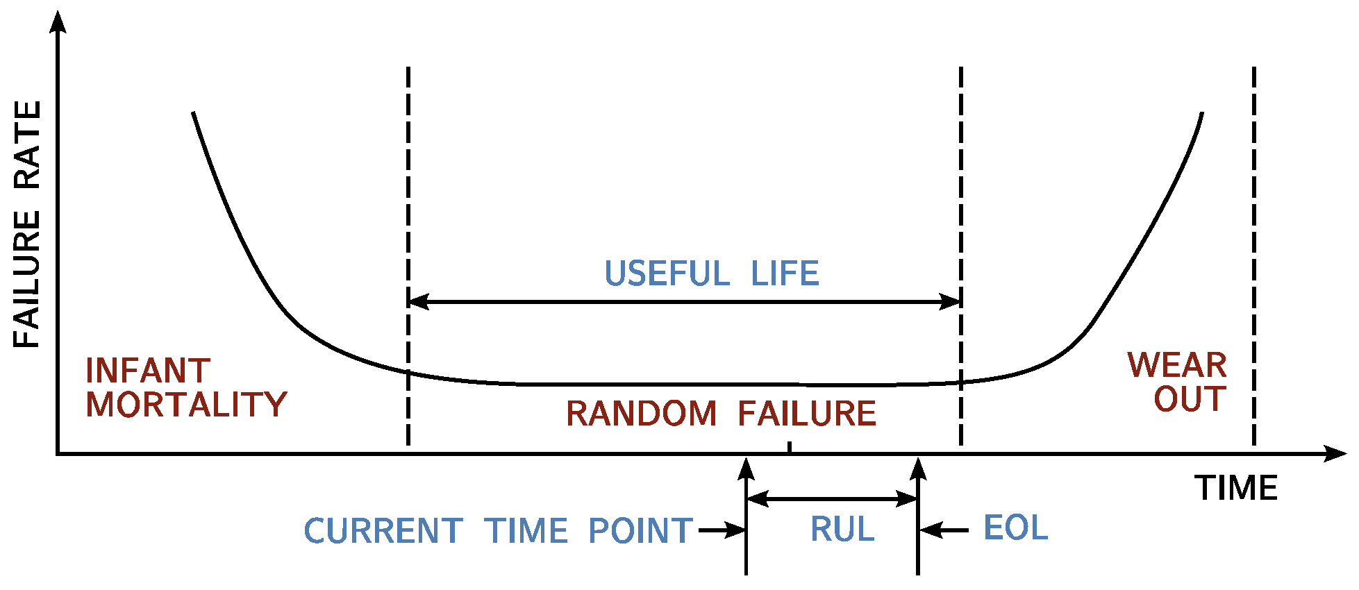
Analyzing the thermal failure mechanism is the basis of life prediction studies. Studies show that the failure rates of most devices change over time in a curve resembling a bathtub, as illustrated in Figure 6. From this curve, we can determine the remaining useful life (RUL) and the end of life (EOL). The horizontal axis represents the operating time, while the vertical axis represents the failure rate. The device’s entire service life is typically divided into three stages: infant mortality (early failure), random (constant failure), and wearout. During the useful life period, the failure rate is generally constant and relatively low. This period is commonly used for life prediction, and the through-life optimization discussed in this article is also based on the operating conditions during this stage [23].

Figure 6.
Typical characteristic visualization of a bathtub curve.
3. System Description
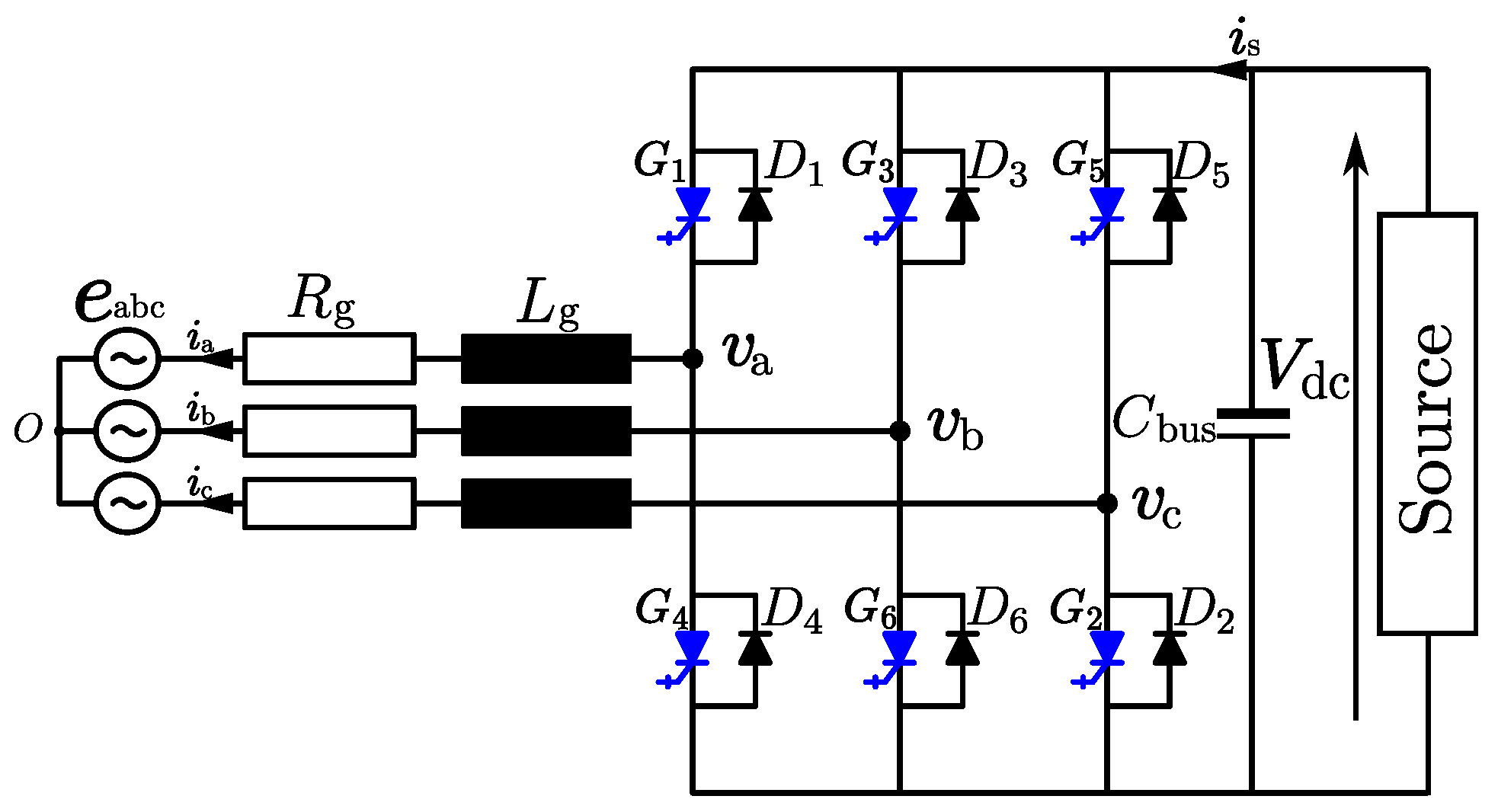
The topology of a three-phase two-level converter is illustrated in Figure 7. The converter consists of three legs. Each leg comprises two IGCTs with two antiparallel freewheeling diodes. The whole converter system also includes filter inductances and resistances , AC power grid voltage (), and DC voltage [24,25,26].
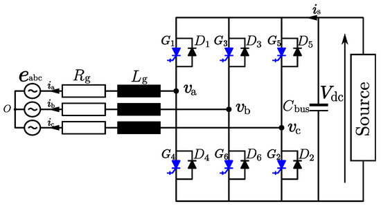
Figure 7.
Topology of a three-phase two-level converter.
Define as
Depending on the eight switching states, the converter generates two different levels of voltage: and 0. By Kirchhoff’s voltage law, the continuous mathematical model can be expressed as
Temperature parameters affecting the lifespan of IGCT are the temperature fluctuation inside the module and the number of thermal cycles. The changes in the internal temperature of IGCT generate different thermal stresses. As the service life of IGCT increases, fatigue damage accumulates, eventually leading to its failure. The key factors influencing the number of thermal cycles of IGCT are mean junction temperature and junction temperature fluctuation [27].
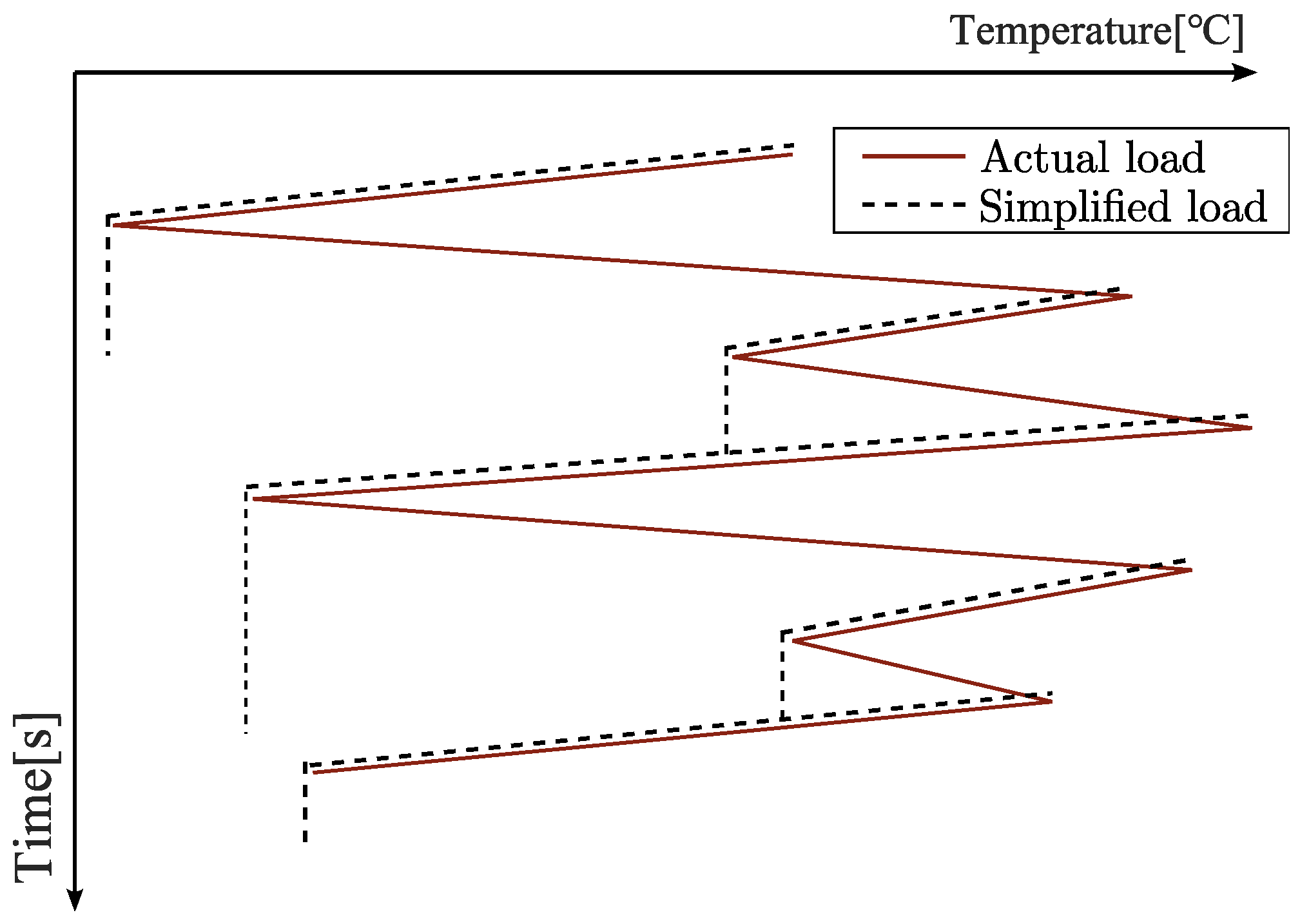
The change in junction temperature of IGCT is a function of time. The rain flow counting method is a classical method for investigating metal fatigue and failure. Rain flow counting simplifies the actual load history into several load cycles, as illustrated in Figure 8, to estimate fatigue life and construct fatigue test load spectra. The fatigue test load spectra record the amplitude and mean value of the load block. This more accurately reflects the real situation of the load. In this simulation experiment, the rain flow counting method will record the mean junction temperature and the junction temperature fluctuation of IGCT in each thermal cycle condition.
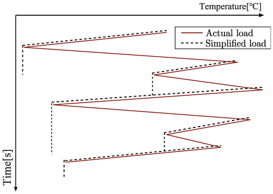
Figure 8.
An example of the rain flow counting method.
The power cycling experiments can save time in studying the main failure mechanisms using a shorter cycling period, and the number of power cycles at different junction temperature fluctuations can be obtained from the accelerated aging experiments to obtain the relationship between the number of cycles , the mean junction temperature , and the junction temperature fluctuation , which is interpolated and fitted by the Lesit equation, which is expressed as
where is the number of power cycles. The other parameters in this equation are shown in Table 3 [28,29,30,31].
Table 3.
The parameters of the Lesit equation.
In addition to the junction temperature related to and , the turn-on time affects the temperature rise in the IGCT. The turn-on time of the switching device varies in different applications; therefore, it should also be taken into account in the life prediction model, and the number of new cycles can be expressed as
where the parameter can be obtained from simulation values.
Assuming that the fatigue accumulation of IGCTs is a linear process, according to Miner’s rule [32], the cumulative fatigue damage of IGCTs after i complete cycles of operating conditions can be expressed by
where is the number of thermal cycles in the operating condition i, and is the thermal cycling capacity.
When the cumulative fatigue damage , it indicates a complete failure of the switching device. However, the fatigue damage of IGCT is an accumulative process, but its complete failure occurs in a split second; it is necessary to divide the whole operation process of the converter into multiple cyclic conditions in a very short time and monitor the change in the junction temperature of IGCT under each cyclic condition in real-time. Through the rainfall counting method, we can obtain the mean junction temperature and the fluctuation of the junction temperature of each cyclic condition and the corresponding junction temperature of IGCT, and thus the fatigue damage of each cyclic condition can be expressed as
In order to calculate the lifespan of the IGCT, we choose as the mean damage in each cyclic condition after cyclic condition i. The lifespan of the IGCT can be calculated by the equation expressed as
where is the remaining life of the IGCT after cyclic condition i, and T is the period of each cyclic condition.
4. Active Temperature and Damage Control
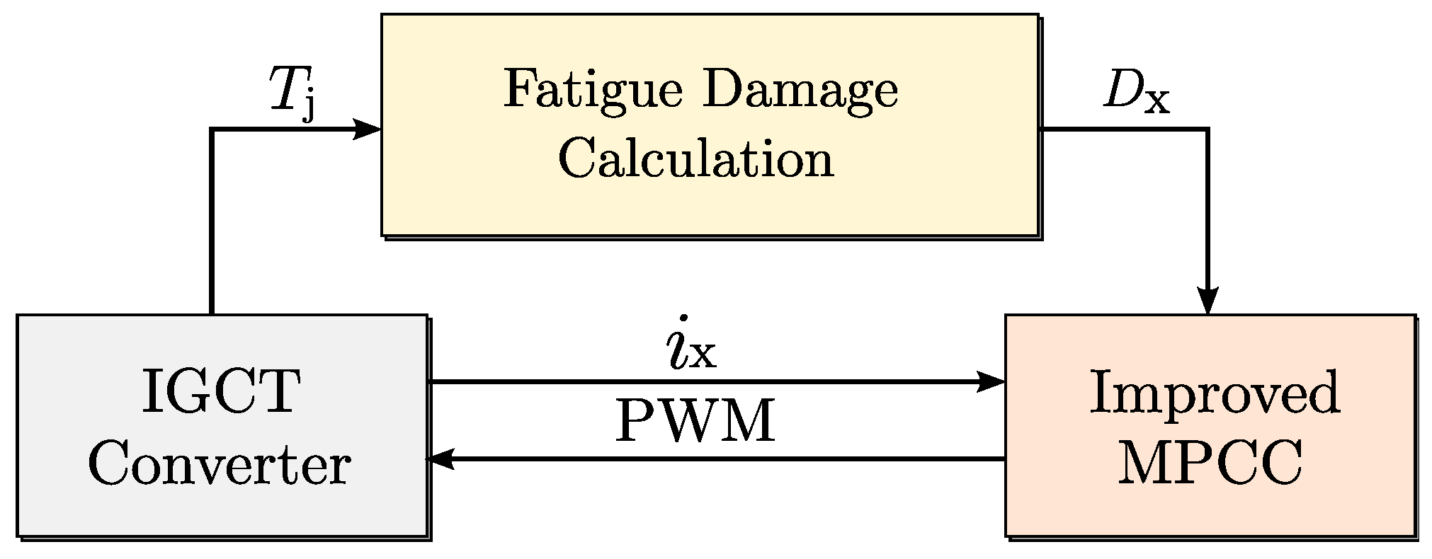
The active damage control system consists of three parts. The conversation among them is illustrated in Figure 9.
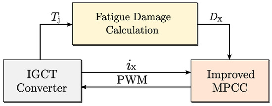
Figure 9.
Three parts of the active life control system.
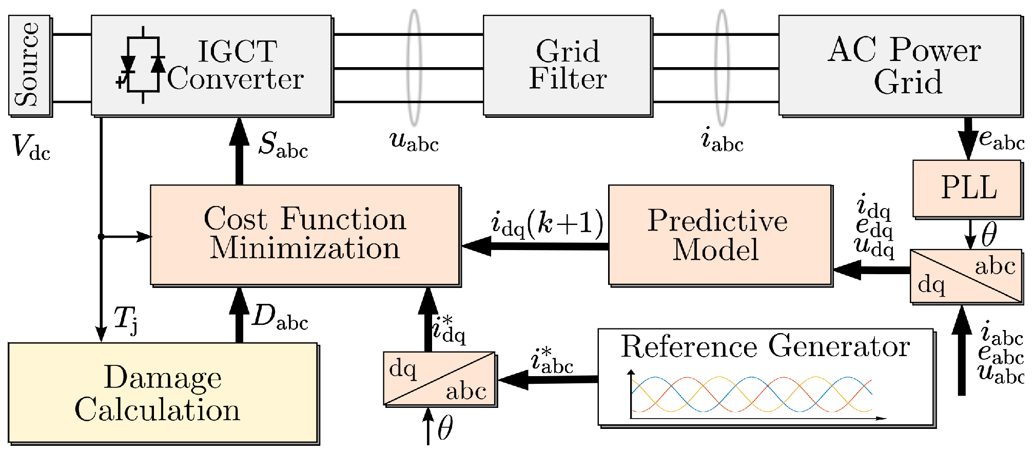
The improved MPCC system sends PWM signals to the IGCT converter according to the output current from the IGCT converter and the cumulative fatigue damage from the fatigue damage calculation program, which calculates the cumulative fatigue damage based on the junction temperature of IGCTs on the three legs of the converter. The improved MPCC structure diagram is illustrated in Figure 10. Based on the AC power grid voltage phase angle, the reference current and converter’s output current are transformed onto the abc-dq coordinates to obtain the current in the dq coordinate system [33,34,35,36,37,38].
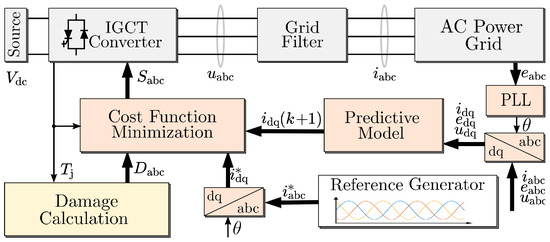
Figure 10.
Model predictive current control structure diagram.
,,, are the variables of the predictive model. These variables can be measured in the converter system. Future current values , can be predicted from the predictive model expressed as
where is the gird angular velocity, is the sampling time, k represents the sampling instant, represents the time instant one sampling time after k, and is the decoupled matrix expressed as
All the above parameters and variables are entered into the predictive model. After iterating through the eight switching states, the specific switching state is chosen to minimize the cost function expressed as
where and refer to the current reference values in the dq coordinate system. They can derive from the abc-dq block, which transforms the reference current from abc coordinates to dq coordinates, as shown in Figure 10. denotes the weighting factor, which is used to deal with the relationship between the reference trajectory and the switching frequency. Larger values of represent that this objective has a higher priority, and in this paper, is in Equation (11) or in Equation (13), depending on whether we are adopting active temperature control or active damage control. In order to guarantee the current output quality, the value of is lower than 0.3 in this paper, and it varies with temperature or fatigue damage. As a result, we make the next momentary switching state.
As a classical life optimization method, the active temperature control method is conducted in this paper as a benchmarking model [39,40,41]. When adopting active temperature control, we suppose that the initial fatigue damage of IGCTs is zero. To lower the junction temperature of IGCTs and guarantee output current quality, the cost function is updated to the equation expressed as
where are junction-temperature dependent. Its value varies from 0 to 0.3 depending on the temperature of IGCT from 100 °C to 150 °C, and its value is 0 if the temperature is less than 100 °C.
However, during the actual operation of the high-power IGCT converter, the cumulative usage time of each IGCT is different, i.e., the initial damage is not necessarily the same. To reduce the O&M cost of the converter, it is particularly important to achieve the life balance of the IGCTs on three legs of the converter. Therefore, it is necessary to appropriately reduce the switching frequency of the IGCT with higher cumulative fatigue damage and increase the switching frequency of the IGCT with lower cumulative fatigue damage based on guaranteeing the output current quality of the converter to make the cumulative fatigue damage of the IGCTs closer to each other.
The cumulative fatigue damage of IGCTs is calculated by the fatigue damage calculation program, and the cumulative fatigue damage of IGCTs is compared to obtain the cumulative fatigue damage differences expressed as
, respectively, represent the cumulative fatigue damage of IGCT on the three legs of the converter. , , and , respectively, represent the cumulative fatigue damage difference between phase A and phase B, phase B and phase C, and phase C and phase A.
On this basis, add the cumulative fatigue damage differences into the cost function expressed as
where , i.e., are the functions of and , and , and and , respectively. The junction temperature is included as well. Based on the cumulative fatigue damage difference after the cycle condition n, the switching strategy is adjusted to reduce the cumulative fatigue damage difference after the cycle condition and subsequent cycle conditions.
5. Simulation Result Analysis
The parameters of the electro-thermal simulation system are shown in Table 4, and the IGCT type used for simulation in this article is 5SHX 26L450, produced by ABB. The relevant parameters of IGCT can be obtained from the data sheet, especially the thermal parameters.
Table 4.
Simulation parameters.
5.1. Active Temperature Control
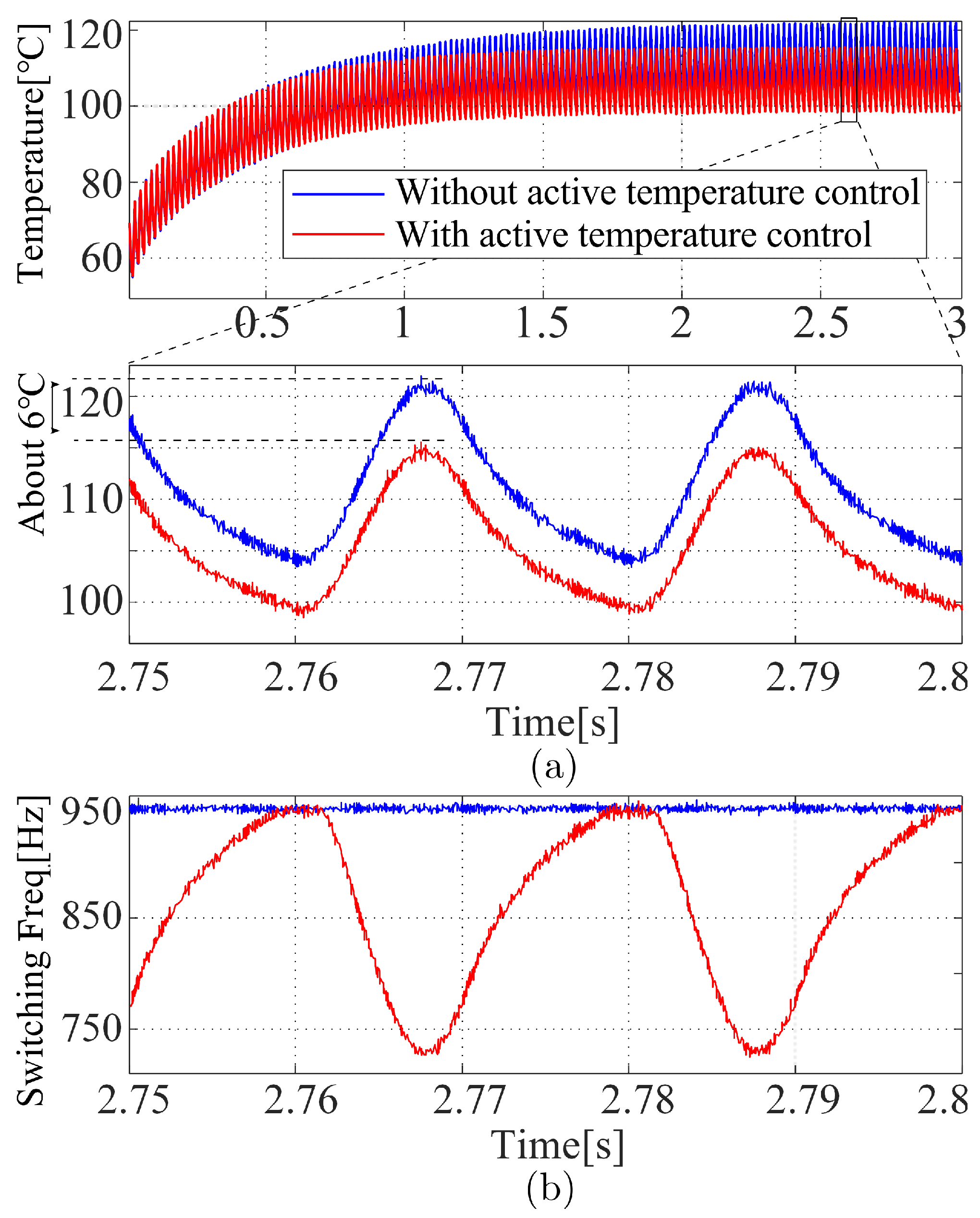
The junction temperature and switching frequency (Switching Freq.) with and without active temperature control are shown in Figure 11.

Figure 11.
The simulation results with and without active temperature control. (a) Junction temperature. (b) Switching frequency.
The comparison of the simulation results is shown in Table 5. The results of this simulation show that the controller can adaptively adjust the switching frequency according to the junction temperature with the active temperature control. This control approach effectively reduces the junction temperature and junction temperature fluctuation, thus improving the lifespan of IGCT.
Table 5.
Comparison of IGCT junction temperature with and without active temperature control.
Based on the junction temperature of IGCT and Equation (3), the maximum number of switching times can be calculated. The results are shown in Table 6. We can see that with active temperature control, the maximum number of switching times of IGCT is more than without active temperature control. Because the switching frequency of the IGCT is reduced, its lifespan is actually increased by more than 30%.
Table 6.
Comparison of the maximum number of switching times with and without active temperature control.
5.2. Active Damage Control
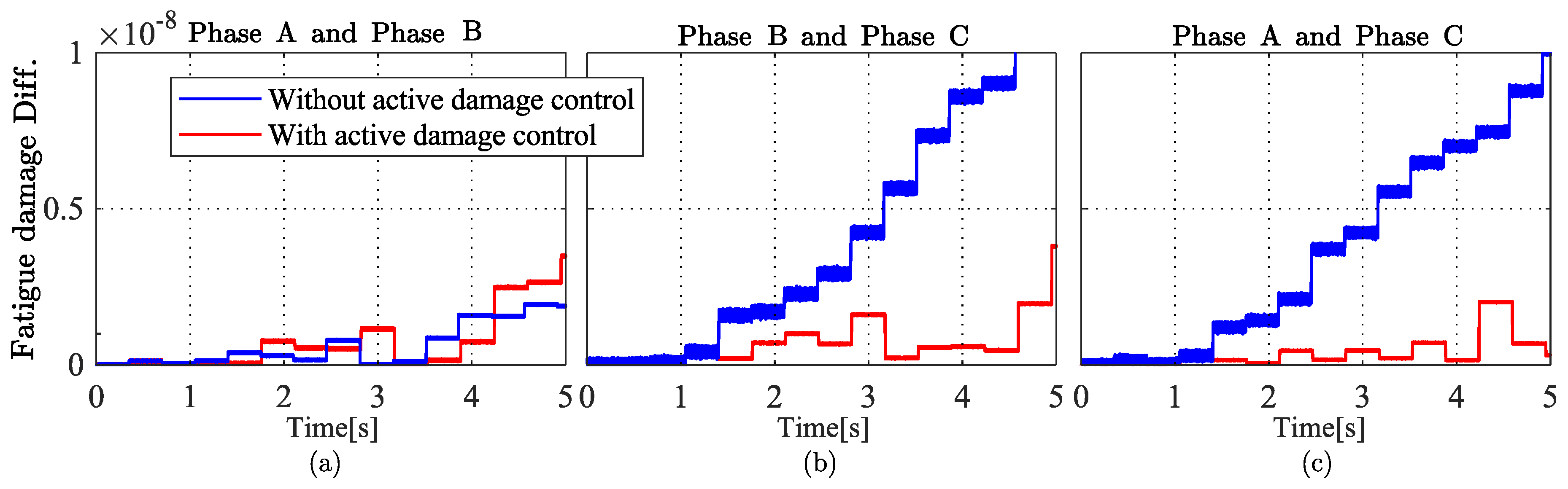
In this section, we analyze two conditions. In the first condition, called the zero-damage condition, we suppose that the initial fatigue damage of the IGCTs on three legs of the converter is zero, i.e., . In other words, all six IGCTs are new. Compare the cumulative fatigue damage differences (fatigue damage diff.) with and without the active damage control, as shown in Figure 12. The switching frequency changes are shown in Figure 13.
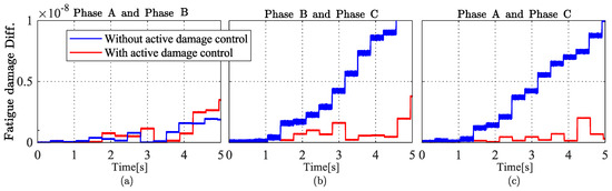
Figure 12.
The cumulative fatigue damage differences when the initial fatigue damage is zero. (a) Phase A and Phase B. (b) Phase B and Phase C. (c) Phase A and Phase C.

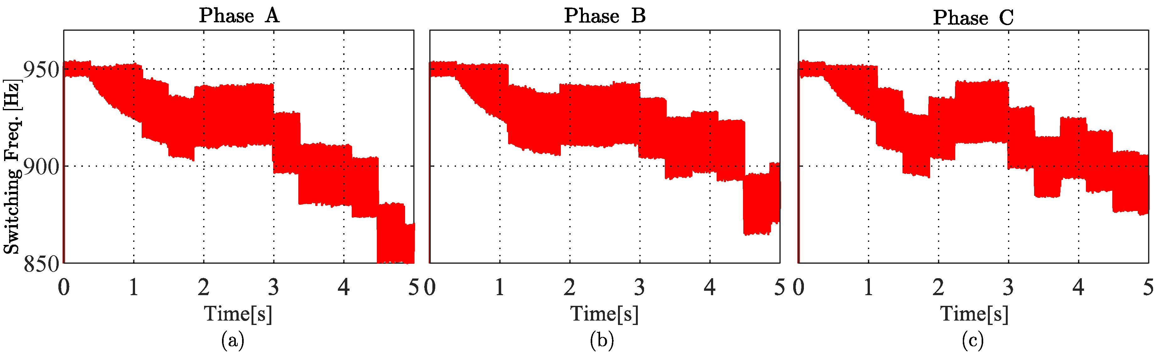
Figure 13.
The switching frequencies when the initial fatigue damage is zero. (a) Phase A. (b) Phase B. (c) Phase C.
In zero-damage conditions, we can see that the fatigue differences between these IGCTs is getting progressively larger with time when this system has not applied active damage control, as shown by the blue line in Figure 12. After we apply active damage control to this system, the differences between IGCTs, as shown by the red line in Figure 12, is still a small value.
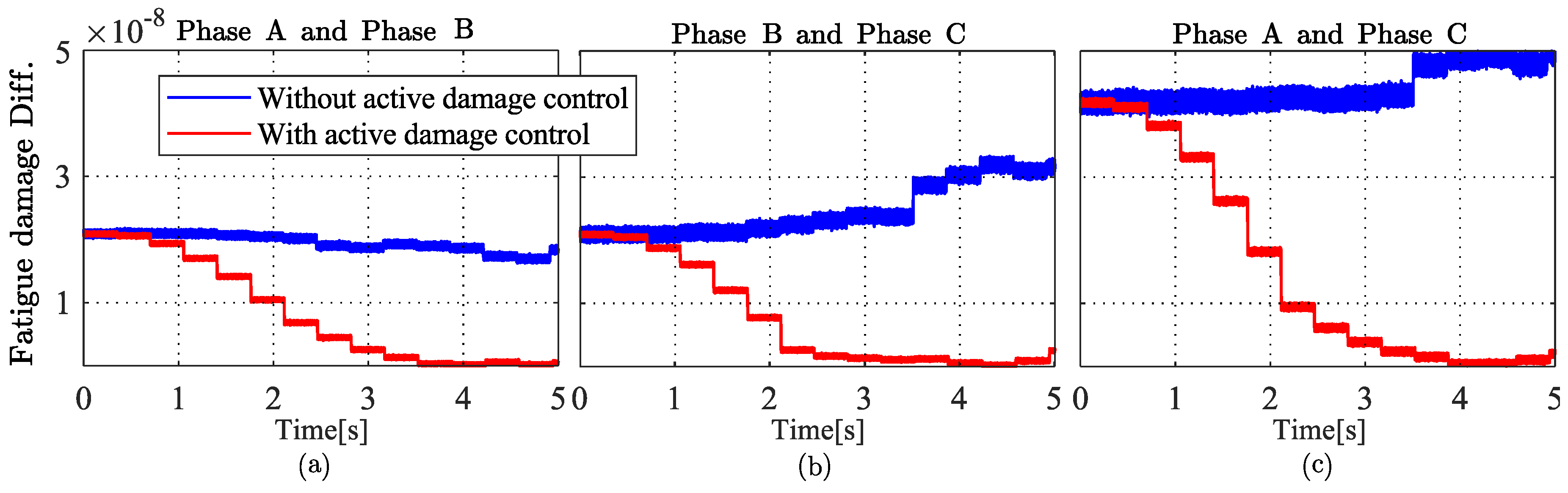
The second condition is that the IGCTs work in different initial states, which we call different damage conditions. During the actual operation of IGCTs, the cumulative fatigue damage differences between the IGCTs on the three legs of the converter are significant. It requires an extended period to adjust. To accentuate this change in the simulation, we assume that the initial damage is a small value. In this case, the converter can finish the adjustment quickly and display the results. Therefore, the initial fatigue damage , , and are input into the controller. The controller adjusts the switching frequency of IGCT to bring the cumulative fatigue damage differences closer to zero. The simulation result is shown in Figure 14, and the changes in switching frequencies are shown in Figure 15.
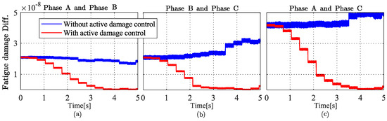
Figure 14.
The cumulative fatigue damage differences when the initial states are different.(a) Phase A and Phase B. (b) Phase B and Phase C. (c) Phase A and Phase C.
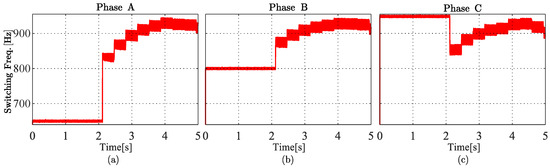
Figure 15.
The switching frequencies when the initial states are different. (a) Phase A. (b) Phase B. (c) Phase C.
The simulation data indicate that when the initial fatigue damage of IGCTs is different, the active damage control approach adapts its strategy based on the fatigue damage differences among the IGCTs on different legs of the converter. By adjusting IGCT switching frequencies, the cumulative fatigue damage differences between them are brought closer to zero. That means the fatigue damage of the IGCTs on three legs is more symmetrical. This approach aims to achieve a balance in the lifespan of IGCTs across the three legs of the high-power converter, thereby significantly maximizing the converter’s utilization.
6. Conclusions
IGCTs, as the core equipment of high-power conversion systems, account for approximately 50% of the converter’s total cost. Proactively controlling the lifespan of IGCT is crucial for extending the lifespan of high-power converters and maximizing their utilization. Moreover, the converter is a highly intelligent device capable of collecting and processing real-time data, and the data resolution can reach 3kHz or even higher with the control platform based on ARM and DSP. These characteristics provide highly advantageous conditions for optimizing its lifespan because this method requires detecting the real-time temperature of the IGCT to calculate its fatigue damage and measuring real-time current and voltage to conduct MPCC.
This article addresses the challenges posed by the high power, high junction temperature, and short lifespan of IGCT. In this article, the three-phase, two-level converters are taken as an example to propose a method that can balance the lifespan of IGCTs on different legs of the converter. Actually, this method can be applied to any symmetric conversion systems as long as the lifespan of their core equipment can be calculate by thermal fatigue damage.
The method of reducing the temperature of IGCT has been studied for a long time. In this paper, we conducted a traditional life optimization approach called active temperature control as a benchmarking model. By taking the temperature into the MPCC, the approach effectively reduces the junction temperature by approximately 6 °C (i.e., about 4.92%). The service life of IGCT under active temperature control can increase by more than . Therefore, it can effectively improve the lifespan of IGCTs and reduce the O&M costs of high-power IGCT converters.
Based on the active temperature control approach for controlling the junction temperature of IGCT, we conducted a further study on actively controlling the fatigue damage of IGCT. It calculates the cumulative fatigue damage of IGCT and incorporates the differences in damage among IGCTs on three legs of the converter as variables input into the improved MPCC method. Additionally, initial damages are taken into account. By adjusting the switching frequency of IGCT based on different damage levels, this control approach effectively reduces the fatigue damage differences among IGCTs on three legs, thereby promoting a more balanced lifespan and effectively maximizing their utilization. Moreover, this control approach can effectively reduce the replacement frequency of IGCT and the downtime of converters, thus enhancing system reliability and reducing the O&M costs of high-power IGCT converters.
Author Contributions
Conceptualization, Z.Z. and Z.L.; methodology, Y.C.; software, Y.C. and Y.Z.; validation, Y.C.; formal analysis, Y.C.; investigation, Y.C.; resources, Z.Z.; data curation, Y.C.; writing—original draft preparation, Y.C. and H.C.; writing—review and editing, Y.C. and H.C.; visualization, Y.C. and Y.Z.; supervision, Z.Z. and Z.L.; project administration, Z.Z.; funding acquisition, Z.Z. All authors have read and agreed to the published version of the manuscript.
Funding
This work is supported in part by the National Key R&D Program of China (2022YFB4201700), in part by the Science Fund for Distinguished Young Scholars of Shandong Province, China (ZR2023J0020), in part by the National Natural Science Foundation of China (52277191), in part by the Shen zhen Science and Technology Program (ICYJ20210324132616040), in part by the Guangdong Province Offshore Wind Power Joint Fund (2022A1515240028), in part by the National Natural Science Foundation of China (52277192), and in part by the Shen zhen Science and Technology Program (ICY120220530141010024).
Data Availability Statement
The authors confirm that the data supporting the findings of this study are available within the article.
Conflicts of Interest
The authors declare no conflicts of interest.
References
- Vemulapati, U.; Rahimo, M.; Arnold, M.; Wikström, T.; Vobecky, J.; Backlund, B.; Stiasny, T. Recent advancements in IGCT technologies for high power electronics applications. In Proceedings of the 2015 17th European Conference on Power Electronics and Applications (EPE’15 ECCE-Europe), Geneva, Switzerland, 8–10 September 2015; pp. 1–10. [Google Scholar]
- Chengsheng, W.; Chongjian, L.; Chuyi, Z.; Zhiming, L.; Qiongtao, Y.; Wei, D.; Fan, L. Study on the over-current protection method of the large power inverter with IGCTs. In Proceedings of the 2013 15th European Conference on Power Electronics and Applications (EPE), Lille, France, 2–6 September 2013; pp. 1–7. [Google Scholar]
- Vemulapati, U.; Bellini, M.; Arnold, M.; Rahimo, M.; Stiasny, T. The concept of Bi-mode Gate Commutated Thyristor-A new type of reverse conducting IGCT. In Proceedings of the 2012 24th International Symposium on Power Semiconductor Devices and ICs, Bruges, Belgium, 3–7 June 2012; pp. 29–32. [Google Scholar]
- Zou, P.; Chen, F.; Zeng, H.; Pan, X.; Chen, Y.; Sun, Y. Research on the Characteristics of Reverse Blocking IGCT and Module for DC Power Grid Application. In Proceedings of the 2020 4th International Conference on HVDC (HVDC), Xi’an, China, 6–9 November 2020; pp. 888–893. [Google Scholar]
- Cai, X.; Chen, G.; Zhou, D.; Zhang, J.; Wang, Y.; Shao, H.; Wang, W. Review and Prospect on Key Technologies for Offshore Wind Power Converters. J. Glob. Energy Interconnect. 2019, 2, 102–115. [Google Scholar]
- Spinato, F.; Tavner, P.J.; Van Bussel, G.J.; Koutoulakos, E. Reliability of wind turbine subassemblies. IET Renew. Power Gener. 2009, 3, 387–401. [Google Scholar] [CrossRef]
- Ma, L.; Huang, J.; Chai, X.; He, S. Life Prediction for IGBT Based on Improved Long Short-Term Memory Network. In Proceedings of the 2023 IEEE 18th Conference on Industrial Electronics and Applications (ICIEA), Ningbo, China, 18–22 August 2023; pp. 868–873. [Google Scholar]
- Wang, Y.; Li, N.; Zhao, W.; Guo, S.; Shen, M.; Li, X. Research on Life Prediction of Inverter IGBT Based on WOA Optimized LSTM Model. In Proceedings of the 2023 IEEE 5th International Conference on Civil Aviation Safety and Information Technology (ICCASIT), Dali, China, 11–13 October 2023; pp. 1475–1479. [Google Scholar]
- Mao, H.; Jiang, H.; Ran, L.; Chen, H.; Xie, Y.; Yang, M. Electrical and Thermal Performances of IGCT in High Voltage DC Circuit Breaker. In Proceedings of the 2022 2nd International Conference on Electrical Engineering and Control Science (IC2ECS), Nanjing, China, 16–18 December 2022; pp. 75–79. [Google Scholar]
- Jianping, S. Study on Thermal Characteristics of IGBT Module with Variable Switching Frequency of Converter. Master’s Thesis, University of Electronic Science and Technology of China, Chengdu, China, 2023. [Google Scholar]
- Quan, C.; Shule, H.; Guoli, L.; Bin, X. Research on three-level loss and junction temperature based on dynamic DPWM. Power Electron. 2023, 57, 131–134. [Google Scholar]
- Luo, H.; Iannuzzo, F.; Ma, K.; Blaabjerg, F.; Li, W.; He, X. Active gate driving method for reliability improvement of IGBTs via junction temperature swing reduction. In Proceedings of the 2016 IEEE 7th International Symposium on Power Electronics for Distributed Generation Systems (PEDG), Vancouver, BC, Canada, 27–30 June 2016; pp. 1–7. [Google Scholar]
- Kumar Prasobhu, P.; Raveendran, V.; Buticchi, G.; Liserre, M. Active Thermal Control of GaN-Based DC/DC Converter. IEEE Trans. Ind. Appl. 2018, 54, 3529–3540. [Google Scholar] [CrossRef]
- Xiang, C.; Du, J.; Sun, S.; Li, J.; Fan, Z.; Yu, T. Lifetime optimization control of three-level auxiliary converter. J. Railw. Sci. Eng. 2024, 21, 328–341. [Google Scholar]
- Rezaeizadeh, A.; Mastellone, S. Reliability and Lifetime Optimal Control for Electric Vehicle Power Converters. IEEE Control. Syst. Lett. 2024, 1. [Google Scholar] [CrossRef]
- Chen, T.; Fu, P.; Huang, L.; Chen, X.; He, S.; Wang, Z. An IGCT Electrical-thermal Unified Model Suitable for Simulation Software. In Proceedings of the 2021 IEEE Pulsed Power Conference (PPC), Denver, CO, USA, 12–16 December 2021; pp. 1–4. [Google Scholar]
- Chen, T.; Fu, P.; Huang, L.; Chen, X.; He, S.; Wang, Z.; Yang, T. An IGCT Unified Simulation Model Based on the Electrical Model and Thermistor. IEEE Trans. Plasma Sci. 2022, 50, 3412–3421. [Google Scholar] [CrossRef]
- Zhou, W.; Zeng, R.; Zhao, B.; Chen, Z.; Liu, J.; Bai, R.; Wu, J.; Yu, Z. Comparative Analysis of Large-capacity Fully-controlled Press-pack IGBT and IGCT: Principle, Structure, Characteristics and Application. Proc. CSEE 2022, 42, 2940–2957. [Google Scholar]
- Falck, J.; Buticchi, G.; Liserre, M. Thermal Stress Based Model Predictive Control of Electric Drives. IEEE Trans. Ind. Appl. 2018, 54, 1513–1522. [Google Scholar] [CrossRef]
- Yang, C.; Peng, T.; Huang, X.; Fan, X.; Tao, H.; Yang, C.; Gui, W. Electrothermal Performance-Based FCS-MPC for Dynamic Thermal Balance Control of Traction Converters. IEEE Trans. Transp. Electrif. 2022, 8, 277–287. [Google Scholar] [CrossRef]
- Novak, M.; Ferreira, V.; Andresen, M.; Dragicevic, T.; Blaabjerg, F.; Liserre, M. FS-MPC Based Thermal Stress Balancing and Reliability Analysis for NPC Converters. IEEE Open J. Power Electron. 2021, 2, 124–137. [Google Scholar] [CrossRef]
- Liu, J.; Pan, J.; Wu, J.; Meng, L.; Liu, F.; Zhu, Y.; Xu, X.; Chen, Z.; Li, Z.; Zeng, R. Experimental Investigation on the Turn-Off Failure Mechanism of IGCT. IEEE Trans. Power Electron. 2024, 1–9. [Google Scholar] [CrossRef]
- Hofmeister, J.; Pena, W.; Goodman, D.; Curti, C. Condition-Based-Events Life Curve: Conceptual View to Support Fault Management of Complex Systems of Overlapped, Distributed Events. In Proceedings of the 2022 IEEE International Conference on Prognostics and Health Management (ICPHM), Detroit (Romulus), MI, USA, 6–8 June 2022; pp. 48–51. [Google Scholar]
- Sado, K.; Hannum, J.; Booth, K. Digital Twin Modeling of Power Electronic Converters. In Proceedings of the 2023 IEEE Electric Ship Technologies Symposium (ESTS), Alexandria, VA, USA, 1–4 August 2023; pp. 86–90. [Google Scholar]
- Zhang, Y.; Li, Z.; Zhang, M.; Chen, H.; Zhang, X.; Zhang, Z. A Fast and Simple Open-Circuit-Fault Diagnosis for T-Type Three-Level Power Converters. In Proceedings of the 2023 IEEE 2nd International Power Electronics and Application Symposium (PEAS), Guangzhou, China, 10–13 November 2023; pp. 691–696. [Google Scholar]
- Pan, W.; Chongjian, L.; Gang, G.; Chunyi, Z.; Chengsheng, W. Research on rectifier system in high power IGCT three-level PWM converters. In Proceedings of the 2015 18th International Conference on Electrical Machines and Systems (ICEMS), Pattaya, Thailand, 25–28 October 2015; pp. 1541–1546. [Google Scholar]
- Vemulapati, U.R.; Bianda, E.; Torresin, D.; Arnold, M.; Agostini, F. A Method to Extract the Accurate Junction Temperature of an IGCT During Conduction Using Gate–Cathode Voltage. IEEE Trans. Power Electron. 2016, 31, 5900–5905. [Google Scholar] [CrossRef]
- Held, M.; Jacob, P.; Nicoletti, G.; Scacco, P.; Poech, M.H. Fast power cycling test of IGBT modules in traction application. In Proceedings of the Proceedings of Second International Conference on Power Electronics and Drive Systems, Singapore, 26–29 May 1997; Volume 1, pp. 425–430. [Google Scholar]
- Haque, M.R.; Eka, S.Z.; Ferdous, S.; Razzak, M.A. Analysis of Loss Profile and Thermal Distribution of Heat Sink of IGBT-Based Asynchronous and Synchronous Buck Converters for EV Charging System. In Proceedings of the 2021 5th International Conference on Electronics, Materials Engineering and Nano-Technology (IEMENTech), Kolkata, India, 24–26 September 2021; pp. 1–6. [Google Scholar]
- Amro, R.; Lutz, J.; Lindemann, A. Power cycling with high temperature swing of discrete components based on different technologies. In Proceedings of the 2004 IEEE 35th Annual Power Electronics Specialists Conference (IEEE Cat. No.04CH37551), Aachen, Germany, 20–25 June 2004; Volume 4, pp. 2593–2598. [Google Scholar]
- Liao, L.L.; Liu, C.K.; Chiang, K.N. Power cycling test and failure mode analysis of high-power module. In Proceedings of the 2016 International Conference on Electronics Packaging (ICEP), Hokkaido, Japan, 20–22 April 2016; pp. 372–377. [Google Scholar]
- Curtis, L.R.; Ayyub, B.M. A Meta-Analysis of Miner’s Rule. In Proceedings of the 2024 Annual Reliability and Maintainability Symposium (RAMS), Albuquerque, NM, USA, 22–25 January 2024; pp. 1–6. [Google Scholar]
- Zhang, Y.; Zhang, Z.; Babayomi, O.; Li, Z. Weighting Factor Design Techniques for Predictive Control of Power Electronics and Motor Drives. Symmetry 2023, 15, 1219. [Google Scholar] [CrossRef]
- Li, J.; Babayomi, O.; Zhang, Z.; Li, Z. Robust Predictive Current Control of PMSG Wind Turbines with Sensor Noise Suppression. Energies 2023, 16, 6255. [Google Scholar] [CrossRef]
- Zhang, Y.; Li, Z.; Chen, H.; Babayomi, O.; Zhang, M.; Zhang, X.; Zhang, Z. A Robust Predictive Current Control of T-Type Three-Level Power Converters Based on Adaptive Linear Neural Network. In Proceedings of the 2023 IEEE 2nd International Power Electronics and Application Symposium (PEAS), Guangzhou, China, 10–13 November 2023; pp. 1122–1127. [Google Scholar]
- Xu, P.; Yang, K.; Tang, T.; Sun, N.; Ye, C.; Song, W. Life Prediction Method for Power Device of Traction Inverter in Metros. In Proceedings of the 2022 4th International Conference on Smart Power and Internet Energy Systems (SPIES), Beijing, China, 9–12 December 2022; pp. 624–629. [Google Scholar]
- Li, J.; Zhang, Z.; Li, Z.; Babayomi, O. Predictive Control of Modular Multilevel Converters: Adaptive Hybrid Framework for Circulating Current and Capacitor Voltage Fluctuation Suppression. Energies 2023, 16, 5772. [Google Scholar] [CrossRef]
- Wang, L.; He, J.; Han, T.; Zhao, T. Finite Control Set Model Predictive Control With Secondary Problem Formulation for Power Loss and Thermal Stress Reductions. IEEE Trans. Ind. Appl. 2020, 56, 4028–4039. [Google Scholar] [CrossRef]
- Li, J.; Sha, Y.; Zhou, M.; Wang, L. Analysis of the Influence of Bond Wire Aging on Junction Temperature Estimation in IGBT Modules. In Proceedings of the 2024 IEEE 7th International Electrical and Energy Conference (CIEEC), Harbin, China, 10–12 May 2024; pp. 4675–4679. [Google Scholar]
- Yang, K.; Chen, J.; Tang, T.; Xu, P.; Song, W. An Optimized Online Monitoring Method of IGBT Junction Temperature based on Switch Overshoot Voltage. In Proceedings of the 2022 IEEE International Power Electronics and Application Conference and Exposition (PEAC), Guangzhou, China, 4–7 November 2022; pp. 1626–1630. [Google Scholar]
- Chen, J.; Deng, E.; Zhao, Z.; Huang, Y. Influence of low junction temperature swing on the power cycling lifetime of bond wire. In Proceedings of the 2021 33rd International Symposium on Power Semiconductor Devices and ICs (ISPSD), Nagoya, Japan, 30 May–3 June 2021; pp. 375–378. [Google Scholar]

Disclaimer/Publisher’s Note: The statements, opinions and data contained in all publications are solely those of the individual author(s) and contributor(s) and not of MDPI and/or the editor(s). MDPI and/or the editor(s) disclaim responsibility for any injury to people or property resulting from any ideas, methods, instructions or products referred to in the content. |
© 2024 by the authors. Licensee MDPI, Basel, Switzerland. This article is an open access article distributed under the terms and conditions of the Creative Commons Attribution (CC BY) license (https://creativecommons.org/licenses/by/4.0/).