1. Introduction
Due to urbanization, the construction industry is one of the largest industries in the world and is experiencing exponential growth. Numerous individuals now enjoy a comfortable lifestyle and can afford to own their own homes. Similarly, many large corporations are expanding their operations by constructing additional manufacturing facilities and corporate offices. Due to the introduction of new construction techniques in recent years, all these advancements are occurring at a faster rate than in the past. Construction machines in several applications can now operate autonomously with minimal or no human intervention, allowing for higher productivity efficiency. Excavators are essential equipment for construction, assisting with the entire construction process in various ways, including digging, crushing, and dumping. Therefore, adopting cutting-edge technologies to enable autonomous operations for these tasks will contribute to cost reduction and safety improvement. Nowadays, drone technology has been widely used in several construction tasks. In this research, a new idea for a drone excavator is introduced in which the platform is able to perform excavation tasks airborne autonomously. The platform has a depth camera that provides the main controller with ground surface profile data by combining 2D images through the triangulation method. It facilitates the accurate identification of excavation sites. Pixhawk Orange Cube is the main independent open-hardware flight controller used for drone control while Nvidia Jetson Nano is used as an onboard PC for taking data from sensors and controlling actuators on the excavator assembly. Several design changes were made in this study before the final platform was selected, which can counteract all the uneven forces during operations. The software architecture was based on ROS Melodic, which is an open-source robotics middleware suite and serves as the main communication bridge among the different components of the platform.
2. Literature Review
Several different studies use drones or UAVs in multiple construction applications that increase productivity and play a very vital role in the completion of the project. One of the most common uses of drones is construction site surveillance, which gives the project managers a detailed overview of the land area and helps them plan and act accordingly. Drones significantly minimize the amount of work and time required to conduct detailed surveys. Drones can also eliminate a significant portion of the human error involved in the process and can collect essential data substantially faster than conventional approaches.
Owing to their compact dimensions and exceptional mobility, Unmanned Aerial Vehicles (UAVs) possess the capability to gather data from significantly reduced altitudes. This involves initiating data collection at ground level and systematically traversing the project area at multiple elevations and vantage points. The results can be analyzed in a few minutes, and operational costs are much cheaper than using airplanes and helicopters. Drones can produce daily aerial photos that can be used to plan the positioning of stored materials and the movement of personnel and vehicles on and near the site, and to flag potential construction problems [
1]. In high-rise construction sites, UAVs with high-precision positions held through GPS can ensure stable flight in wind speeds up to 55 km/h. These modules have a set of predetermined waypoints that enable capturing the construction site from a top aerial view and tracking actual progress against the planned one [
2]. Using high-resolution photographic systems that are customizable and complement a wide range of applications and software, the integration of overlapping images obtained via Unmanned Aerial Systems (UAS) culminates in the creation of a mosaic. This mosaic can subsequently be translated into high-resolution 3D surface models where each pixel from the original images is projected onto the digital surface model, serving various purposes such as topographic mapping, volumetric calculations, and the generation of comprehensive three-dimensional representations of construction sites. The utilization of UAS images facilitates the creation of various three-dimensional constructs, including architectural models, contour maps, and volumetric surveys [
3]. Photogrammetry is a technology discussed in [
4] that converts 2D images to 3D models. A combination of these models with Lidar data captured by UAVs helps create more accurate 3D building models, contour maps, volumetric surveys, etc. A drone could investigate leaks in high-rise buildings near a busy highway, where UAV operators can detect potential water leaks in pipelines in minutes without impeding traffic and at a lower cost and safety risk [
5].
UAVs are sometimes equipped with manipulator arms, enabling them to perform tasks such as picking, grasping, hammering, etc. The study in [
6] presented the AERIAL-CORE project, which can assist in the repair of power lines, their maintenance and inspection, as well as the quick delivery of tools in case of a breakdown. This reduces risks for human operators who work closely with high-voltage power lines, and the time and cost associated with scheduled maintenance. A novel aerial manipulator with a cutting-edge end effector is discussed in [
7] to address the aerial physical-interaction problem. It would be very useful in cutting high-height trees in any forest areas that are inaccessible to workers or pose a significant safety risk due to the compact symmetry of the trees. A three-robotic-arm manipulator can be used primarily for manipulating and grasping objects since its platform can land on any uneven surface to pick up and drop objects [
8]. The study referenced in [
9] devised a mantis claw that operates without the need for an external power source in which the claw autonomously opens upon contact with a surface. In this design, grasping is dependent on the shape of the objects as it cannot pick objects with irregular shapes. As soon as the drone leaves after picking up the object, the claws become closed. To enhance efficiency, the authors in [
10] introduced an electromechanical gripper designed for autonomous drones. This gripper is characterized by its portability, affordability, and self-diagnostic capabilities. The gripper is equipped with a built-in measurement mechanism to ascertain the success of the grip, complemented by an energy-efficient design. A quadcopter is presented with an angular gripper in [
11] that allows any aerial torsional manipulation to remove light bulbs. As one of the most booming industries, construction makes use of aerial manipulators in several applications. The growing demand for drones necessitates innovative concepts in this sector to speed up the job process.
The need to use UAVs in different applications like delivery, law enforcement, first aid, and emergency service has increased drastically in recent years. For the autonomous working of any UAV platforms for sensing and pathway creation, planning is one major module of the system that serves a vital role in giving the correct direction to move forward. In [
12], the authors introduced a method for performing CPP (Coverage Path Planning) in 3D environments tailored for Unmanned Aerial Vehicles (UAVs), denoted as 3D Dynamic CPP (3DD-CPP). This approach is specifically crafted to navigate in unknown environments through a blend of linear optimization and heuristics. The model is designed for estimating cost matrices, considering UAV power consumption, and it undergoes evaluation across a range of flight speeds. The proposed heuristic possesses reoptimization capabilities, facilitating its use in environments where only local knowledge is available. In [
13], the paper discusses an autonomous navigation method for drones, focusing on a machine-learning-based 3D path-planning approach. This AI-driven method involves the intensive training of an onboard machine responsible for autonomous UAV navigation. Through training, the UAV gains a perception of its environment, like how a human perceives its surroundings. During missions, this perception system detects and localizes objects within the environment. Building upon this AI foundation, this work introduces a real-time three-dimensional (3D) path planner. This planner guides the UAV to its destination along an obstacle-free path by leveraging the relative positions of detected objects (obstacles), ensuring collision-free navigation. Notably, this path planner is lightweight and highly efficient, making it well-suited for real-time applications. In [
14], a UAV-based autonomous motion-planning and object-finding system for outdoor environments, addressing uncertainty and partial observability, is discussed. The proposed system architecture adheres to a modular design, distributing the majority of computationally intensive tasks to a companion computer onboard the UAV. This approach aims to deliver high-fidelity results, particularly in simulated environments. In [
15], a reactive real-time sliding-mode control algorithm is proposed. This algorithm guides a team of communicating UAVs, each equipped with ground-facing video cameras, toward moving targets with the aim of improving some measure of sensing coverage. Additionally, the Voronoi partitioning technique is adopted to limit the movement range of the UAVs and reduce target revisit times. This approach addresses the challenge of autonomous navigation for the UAV surveillance of multiple moving ground targets. In [
16], the authors present a formulation for UAV fly-path tasks in various natural disaster scenarios, considering the specific perception requirements. They propose a Convolutional Neural Network (CNN) model for object detection and localization, including buildings. Additionally, an optimization method is introduced to determine the optimal flight path, enabling the accurate recognition of as many objects as possible while minimizing time costs. In [
17], a new model-free reinforcement-learning method is introduced, offering the capacity to learn the optimal planning and control policy from flight data. In the training phase, this method considers the complete drone state and environmental data as inputs. It undergoes self-optimization by using a predefined reward function. In practical applications, inputs from both onboard and sensors are incorporated, allowing optimal control commands to be generated for low-level velocity controllers in an end-to-end manner. With this approach, drones can navigate complex and harsh environments at high speed without requiring a precise system model through improved control and planning policies. The hybrid navigation method is suggested as a means of improving safety for autonomous operations in partially unknown and dynamic three-dimensional (3D) environments. It integrates a global path-planning algorithm, specifically RRT (Rapidly Exploring Random Trees) connected with SMC (sliding-mode control)-based reactive control laws. Through this, a rapid reflex-like response to newly detected obstacles can be achieved, which is demonstrated in [
18].
The authors of [
19] introduce a drone-perception system featuring accelerated onboard computing; advanced UAS communication technologies; and algorithms for tasks including swarm membership, formation flying, object detection, and fault detection utilizing artificial intelligence. It is observed that the development of a cooperative drone swarm and its integration into a bespoke UAS for infrastructure inspection is eminently feasible given the contemporary state-of-the-art electronic components, software, and communication technology.
In reviewing the above existing studies, a research gap in construction is identified. The use of drones has been limited to mapping, surveying, and image collection. Thus, the idea of an autonomous flying excavator is proposed in this study by mounting an excavator assembly on the top of a quadcopter. The developed excavator platform demonstrates successful autonomous operations such as flying to the excavation site, digging the soil, and dumping it at the designated location during the mission.
3. Challenges and Design Changes
Over the course of this study, several design changes were made to the platform before selecting the final prototype since it is quite challenging to take into account all the issues required for fully autonomous excavations in the air. For example, due to its limited mounting space, the platform is equipped with a compact and complex mechatronic system where the electrical harnessing is carefully secured by ensuring that wires generating magnetic fields are separated from the drone’s compass, which can interfere with sensor readings. In addition, the mechanical components are tightened with nylock nuts so that they can endure vibrations during flight and will not be easily dislodged. Voltage from the battery is passed through a step-down regulator so that each component receives power proportional to its rating. The GPS is mounted on a stand to prevent any magnetic interference, and the ESCs (Electronic Speed Controllers) are fine-tuned to send the correct amount of pulse-width modulation (PWM) signals to the motors. After assembling all the system’s components, the combined center of mass is located in the middle of the platform, enabling it to lift vertically. The legs are constructed so that the drone rests at the optimal distance from the ground to excavate without causing a significant moment arm that may cause the platform to tumble during the lift. The battery weight accounts for a substantial portion of the platform’s weight; therefore, it is crucial to select the appropriate battery based on its weight distribution and power rating to ensure a sufficient run time to complete the desired work without causing instability. Concerning control, it is difficult for a drone to remain in the exact spot throughout the entire excavation process in flight mode since this demands the high-precision ESC calibration and tuning of copters to ensure that all motors are always aligned and synchronized. The copter is Autotuned by using Ardupilot, wherein the flight controller automatically adjusts the PID (Proportional Integral Derivative) gains during flight and stores them for smooth flying. All components were designed in Solid Works before being assembled so as to not interfere with the copter’s rotor blades. Through simulation and an inverse kinematics analysis, it was ensured that each joint functions correctly and does not cause interference with one another. The components were then 3D printed and assembled.
In addition, the platform’s design changed throughout the study in terms of the type of copter and the manipulator as well as the positioning of each component. In the first concept, we combined the F450 frame of the quadcopter with the boom, arm, and bucket of an excavator. As depicted in
Figure 1, it is the most basic version of the quadcopter with the manipulator on top and all the other components attached to the bottom plate. However, this design failed because of its instability during flight since the platform’s center of mass was significantly shifted away from the center, causing unequal weight distributions and eventual collapse. Despite multiple attempts, the objective of autonomous excavation in flight mode was not achieved.
Following that, we replaced the quadcopter with the Tarot Octocopter, which is significantly larger than its predecessor. With the second design modification, depicted in
Figure 2, the platform was successfully stabilized during excavation operations as it was equipped with eight Emax Grand Turbo motors capable of lifting huge loads and counteracting the back-tilting force. Nonetheless, the large weight of the second design platform, around 20 kg, makes it difficult to regulate and keep the same position throughout the whole excavation process, resulting in continuous deviations from the intended position. Due to this fault in position accuracy, the sensor mounted on the platform was unable to detect the target ground for excavation. After several experiment-related failures, as depicted in
Figure 3, we considered another design change to solve this problem.
In the third successful design modification, we replaced the boom with a bracket, decreasing the overall manipulator length from 410 mm to 374 mm. The CAD model of the modified design is shown in
Figure 4. This enables the platform to employ only two actuators for the arm and bucket, improving its balance. To sustain the load and neutralize the counterforces acting during the autonomous excavation process, motors with higher thrust ratings were installed to replace the existing motors. In addition, the legs were shortened from 300 mm to 100 mm to prevent the rotorcraft from tumbling over. The overall dimensions of the platform are shown in
Figure 5.
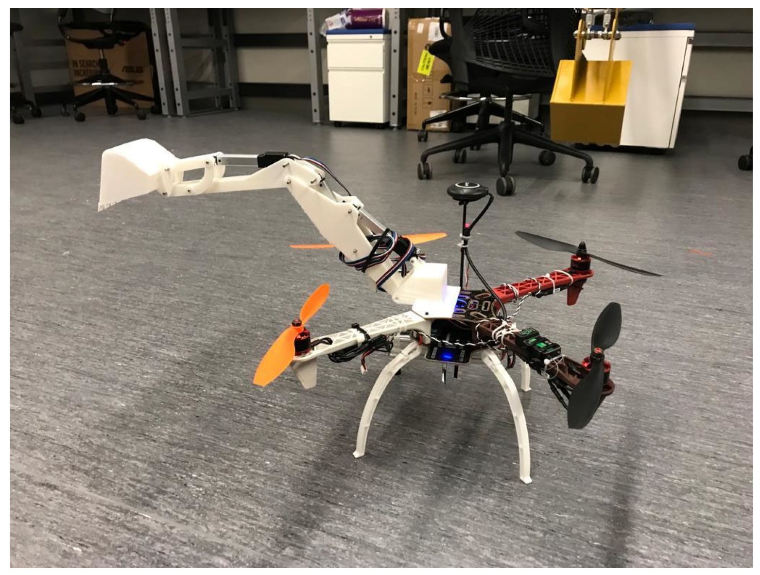
4. Working Methodology
With several modifications, the aforementioned design issues were addressed, and thus all platform components were successfully assembled. In the final design, two electronic linear actuators were used to manipulate the arm and bucket. Nvidia Jetson Nano as the main controller is mounted at the base of the platform alongside the 4S Lipo battery to lower the platform’s center of gravity and increase its stability. The finalized design is shown in
Figure 6.
The system comprises a UAV with an F450 mm frame, fitted with an Orange Cube Pixhawk controller, and a Here 3 GPS system. This configuration is accountable for a UAV flight’s stability under varying load situations and agility. The Pixhawk controller is set up by using the open-source Ardupilot platform, enabling the utilization of multiple sensor modules, including the IMU, magnetometer, and internal GPS data used for seamless flight [
20]. By calibrating the ESC, which is one of the most important steps for setting up a flight controller, all motors are synced with PWM signals. The drone’s motor is powered by a 4S battery cell running at 13,200 RPM, which is optimal for stability and flight. Each motor can lift 3.1 kg by employing 10″ × 5″ propellers and consuming approximately 47 amps of current. It is important to have a lightweight controller that can be mounted on the drone, uses less power from the battery, and provides higher processing power. The selected Jetson Nano meets this requirement and includes a four-core processor and four gigabytes of RAM.
The autonomous excavation features of the developed platform were evaluated under two different scenarios. In the first one, the drone’s ability to fly autonomously from its home location to the target excavation site was tested by providing it with the coordinates via the mission planner. After landing at the target location, the drone detects excavatable soil, scoops it into a bucket, and dumps it at the specified location. Upon completion of the dumping, the drone returns to its original position. [
20].
In the second scenario, the user plans the first mission by using the mission planner interface. This involves specifying an excavation site point, and once the copter is armed, the user switches it to auto mode to execute the mission. In the mission, the copter navigates autonomously to an excavation site and hovers above the soil so that the sensor is able to collect information about the environment and deliver it to the main controller. to locate the bucket’s tip at the designated point. The sensing algorithm developed by using a depth camera D415 is capable of detecting ground and creating a 3D point cloud map used for excavation. For excavation, only the points inside the region of interest (i.e., the excavation area) are relayed to the controller for processing, which then instructs the excavator to begin digging from the correct spot. To achieve the aforementioned processes and functionalities for completely autonomous operation, an ROS (Robot Operating System) was used for the entire software architecture.
5. The Platform’s Navigation System
The prototype excavator drone’s navigation is controlled by three components: GPS, RTK (Real-Time Kinematics), and a mission planner. The mission planner provides an interface for registering all waypoints in an autonomous mission in which user-supplied positions will be transformed into longitude and latitude coordinates for the GPS module mounted on the drone’s body.
In this study, pinpoint accuracy is of the utmost importance since the excavation platform must be accurately located at a specific location. Thus, RTK technology was used in order to enhance the accuracy of the drone location as it allows the drone to fly with a positional accuracy of 25 mm. As depicted in
Figure 7, the RTK system was configured by initially connecting the system base to the mission planner on the user’s laptop. Subsequently, a MAVlink connection was established via telemetry between the Pixhawk controller, the user’s laptop, and the base. This setup allows the mission planner interface to receive location data from the drone’s Here 3 GPS. In this configuration, the RTK system can receive satellite signals, correct the location error, and transmit the drone’s updated location to the onboard Here 3 GPS, enabling the drone to be located at the corrected point. The RTK system’s operational principle is as follows: RTK measures the distance by comparing a code generated by a satellite and the receiver’s equivalent internal code. The time difference between the two codes multiplied by light speed gives the distance. There are two receivers in RTK: one at the base station and the other on the drone. Using the GNSS (Global Navigation Satellite System), the base station computes its location and corresponding errors, which are sent to the drone’s receiver in real time. The drone’s receiver uses these data to achieve more accurate positioning. Among the flight modes of the copter, such as auto, stabilize, loiter, and position hold, the main flight mode, ‘auto’, was used in this experiment, in which the copter executed a preplanned mission autonomously by locating itself at the excavation site based on coordinates from the GPS system.
6. Detection Technique (Sensing Algorithm)
A D415 depth camera was used to detect the point cloud data of the excavation soil. As suggested by the manufacturer, the camera was initially positioned on the back of the platform at 450 mm. However, detection was achievable within a range of 160 mm after adjusting the camera parameters such as the depth breadth, height, and fps, and the camera was subsequently mounted on the front of the platform. CAD model simulations were conducted to crosscheck and eliminate interference between manipulator components and drone rotors.
The whole algorithm for the detection using a D415 consists of a series of steps, as illustrated in
Figure 8. In the first step, a cropping approach was employed to remove extraneous points and reduce the number of
x and
z points. Points within the region of interest (−0.1397 and +0.1397 m along the
x-axis and +0.16 and +0.2 m along the z-axis) were transmitted to the controller for processing in the ROS environment. The D415 depth camera offers a standard field of view of 69° × 42° with shutter sensors capable of producing high-quality depth images. It mimics human binocular vision, utilizing two cameras positioned a short distance apart. The camera’s software identifies identical features of an object in each sensor, leveraging the slight positional variance to determine object depth via the triangulation method. Once the depth image is obtained, it is processed by using the ROS package to convert it into point cloud data. These data are then refined and cropped by using voxel-grid filtering to isolate the region of interest. The resultant point cloud data provide the coordinates, which are transmitted to the autonomous flying excavator to initiate the excavation.
In the defined coordinate system, the x-axis is defined as the axis into the page or the forward axis, while the z-axis represents the direction from top to bottom. The y-axis represents the longitudinal or horizontal axis and was not considered. This is because excavation was performed solely along the x and z axes only in this study. It is also necessary to filter out the points because the data from the point cloud are too large for the Jetson Nano to process quickly and handle the information.
The ROS includes a component called RViz that enables the perception, cropping, and processing of the depth camera’s point cloud in the simulation. In Rviz, the fixed frame is the camera link, and the chosen profile to represent the point cloud is Flat Squares with a length of 0.01 m. Three topics are shown in
Figure 9: /camera/depth/color/points shows the points in the field of view and /voxel_grid/output shows the filtered data of the field of view. Here, the voxel-grid filtering method was also employed to minimize the number of points so that the limited computer resources could be maximized.
/Filtered_two shows points that have already been filtered and cropped along the x and z axes. So, the /Filtered_two topic was selected to process only points within the region of interest. The gathered-soil point cloud 3D data were processed by the C Pluss Pluss (CPP) code to provide the Arduino board with soil coordinates. The default parameter values of the camera, such as ‘depth width’, ‘depth height’, and ‘depth fps’, were modified based on platform requirements. We set the depth width to 424 mm, the depth height to 240 mm, and the depth image’s frame rate to six frames per second.
The developed algorithm (Algorithm 1) for drone control takes the
x and
z coordinates of the point cloud and the bucket’s final angle as inputs. Subsequently, it publishes the lengths of the arm and bucket actuators to the Arduino, enabling the bucket to move accordingly. This process is repeated for excavation with an additional check for the dumping state of the bucket. There will be no camera point clouds sent to the Arduino when the bucket is in the dumping state since the ground surface does not change in this case.
| Algorithm 1 Excavator Control—Steps |
Input: x and z coordinates of camera point cloud and bucket final angle
Output: stroke length of arm and bucket actuators
Step 1. Class Definition:- -
Define private variables: ‘actuator_length’, ‘publiser_arm_actuator’, ‘publiser_bucket_actuator’, ‘subscriber_arm_actuator’, ‘subscriber_bucket_actuator’, ‘no_of_iteration’, ‘Dumping_state’, and ‘first_iteration’. - -
Define methods: ‘subscribe_and_publish’, ‘xzcameracallback’, and ‘triggercallback’.
Step 2. Initialization:- -
Initialize subscribers for ‘xz_camera’ and ‘Triggered’ topics. - -
Initialize publishers for ‘actuator_length_to_arduino’ and ‘sending_xyz_coordinates’ topics.
Step 3. Callback Method (xzcameracallback):- -
Set initial values for ‘x’, ‘z’, and ‘bucket_angle’. - -
If not in the dumping state: - -
Check if the first iteration is true. - -
Adjust values based on the message data. - -
Clear and publish ‘actuator_length’ data.
- -
If in the dumping state:
- -
Clear and publish zero data for ‘actuator_length’.
Step 4. Callback Method (triggercallback):- -
Set the ‘first’ value to true. - -
Toggle the ‘Dumping_state’.
Step 5. Main Function:- -
Initialize ROS node. - -
Begin the ROS spin process. - -
Return 0 to exit.
|
In Steps 1 and 2 of the above algorithm, defining variables and setting a publisher and subscriber are performed, in which ‘xzcameracallback’ is the one that obtains the camera points in each cycle and ‘actuator length’ represents the lengths of the arm and bucket actuators to place the bucket at the correct position.
Steps 3, 4, and 5 check whether the platform is in the dumping state or needs the coordinates for the next cycle, and this process is repeated until the excavation is complete. This algorithm controls the drone’s actuators by using the camera input and trigger signals. It manages the dumping and nondumping states to ensure proper excavation operations.
The entire process is controlled by the main CPP code, which receives the camera’s point cloud data from Intel RealSense’s ROS packages. These data points are then inputted into the kinematic equations to compute the lengths of the arm and bucket actuators. Subsequently, the resulting values are transmitted to the Arduino so that the actuators can be triggered, ensuring precise bucket positioning.
7. Major Components of the Platform and Sensor Calibration
The most significant component of platform design is selecting the correct frame size for a drone by considering the manipulator’s mounting position. This prevents the drone from falling during flight and assures its successful operation. The selection of an appropriate motor is also critical to maintaining an optimal thrust-to-weight ratio as it is the primary source of thrust and balance for the whole platform during operation. Autonix actuators with integrated PID controllers were utilized to regulate the bucket tip’s position based on inverse kinematics for the excavator’s manipulator. The main components of the developed platform are summarized with their functions in
Table 1.
The camera was calibrated to obtain more refined data from the environment. The Pixhawk Cube Orange contains several sensors, such as a magnetometer and an accelerometer for smooth flight control, which were calibrated during Pixhawk setup by using Ardupilot. For magnetometer calibration, one should click on the “Onboard Mag Calibration” section’s “Start” button on the Ardupilot’s user interface and then hold and rotate the vehicle in the air from each side (front, back, left, right, top, and bottom). It should undergo approximately six full turns in the air to achieve proper calibration. An accelerometer was calibrated with Ardupilot by placing the copter in different positions: level, left side, right side, nose down, nose up, and backside. After completing all the steps, a mock flight was performed to ensure that all the sensors were calibrated perfectly.
Finally, the trusts required to support the navigating platform consisting of the above components in two excavation modes (i.e., after landing and airborne; see
Section 8 for details) were calculated. This info was used to determine the right motor size.
Table 2 presents the calculated thrusts to ensure a successful flight under the two modes. Several assumptions were made to simplify the calculations, including negligible air resistance and constant atmospheric conditions, which could occur during the experiments in
Section 8.
8. Experiment
Several drones are utilized in the construction industry for a variety of activities, but there has been no research on excavator drones. The objective of this project is to design a construction drone with excavation capabilities. This section will cover the experiment conducted with the final prototype excavator drone and its feasibility.
In the first scenario for experiments, the drone took off from the initial position (
Figure 10a) to approach the target site, which was 3 m away from the initial position (
Figure 10b). As illustrated in
Figure 10c, the excavation ground was autonomously recognized and dug by the drone after landing. Upon completion of the excavation, the drone excavator dumps the sand collected in the bucket (
Figure 10d). Its task was accomplished when the prototype landed at the predetermined location after dumping.
Figure 10e shows its safe landing after completing the excavation mission. White circles highlight the developed drone in the figure.
Figure 11 depicts the whole flight path in Scenario 1, where the blue and red lines represent the desired flight path and the drone’s actual flight path, respectively. The green line shows the drone’s desired path for soil disposal and arrival after collecting soil, while the black line represents the corresponding actual path. As seen in the figure, the developed prototype achieved autonomous excavation by managing positional precision and stability in Scenario 1. During the experiment, the platform flew through the same line five times, along with the desired path having a vertical distance of 1.5 m and a horizontal distance of 3.0 m, which was randomly selected according to the rough estimate of the battery timing. Using the RTK system and GPS, the platform’s position was established with centimeter-level precision. During the experiment, the target landing and actual landing positions for excavation are (0.000, 3.000) m and (0.004, 2.992) m, respectively. The RMSE value between the desired trajectory (blue line) and the actual flight path (red line) is 0.00894 m. The platform then finished the aerial dumping procedure and landed at the destination. In this case, the targeted and landing locations are (1.500, 2.992) m and (1.492, 2.995) m, respectively, and the RMSE between the desired path to the desired path (green line) and the actual one (black line) is 0.00854 m. For stability, the maximum permitted lean angle in loiter mode where the excavation was conducted is 30 degrees, and our drone maintained an average lean angle of 20 degrees throughout the entire experiment [
20].
In the second scenario, the drone’s performance was evaluated airborne. In this test, the target sand for excavation was held on top of a tall box to maintain a certain height, and the drone was tasked with reaching the designated location and excavating without touching down.
Figure 12 depicts the experimental setup (a to d). In
Figure 12a, the platform was at a home location ready to take off in order to reach the top of the box. The platform successfully approached the target location by using RTK and GPS, which were helpful in achieving navigational objectives (
Figure 12b). The platform excavated the soil autonomously in the air after reaching the designated target landmark (
Figure 12c). Although the manipulator broke stability, the platform remained balanced during excavation. Then, it safely landed, as shown in
Figure 12d. The drone is highlighted in each diagram with a white circle.
Figure 13 depicts that the platform attempted to perform the excavation task after flying autonomously to the target location (sand), which was placed at an elevation of approximately 0.75 m. In the figure, the blue and red lines indicate the desired and actual flight paths followed by the platform. The specified coordinates for the target and landing locations in the
x and
z dimensions are (3.0, 0.75) meters and (2.98, 0.73) meters, respectively. The Root Mean Square Error (RMSE) between the desired path (blue line) and the actual path (red line) is calculated to be 0.02 m, indicating high accuracy. The maximum lean angle that the platform reached was 20 degrees, which falls within an acceptable range. With loiter mode set to ensure stability, the maximum lean angle of 20 degrees was attained during excavation, while the average lean angle maintained throughout the experiment was 15 degrees.
9. Conclusions
Drone technology has solved the problem of accessing dangerous or inaccessible areas for humans. It has been deployed for surveillance, transportation, and monitoring across numerous industries. The construction industry, being a significant economic contributor in any country, utilizes drones for various purposes. However, despite their widespread use, innovative ideas such as excavator drones have not yet been utilized in excavation, which is one of the most essential tasks in construction.
In this study, a drone excavator platform was presented, which represents the first trial in this field. A successful autonomous excavation was achieved following several design changes. The design underwent testing at multiple stages of its development. Inverse kinematics was applied in the design of the excavator manipulator and the positioning of the end effector as a digging tool. This was equipped with an onboard computer that executes a custom-designed sensing algorithm to determine the operation’s target area. The algorithm creates a 3D map to obtain information about the digging site by using point clouds obtained from a 3D depth camera. Then, the onboard computer sends signals to the actuators to position the bucket at the target location and commence excavating in flight. A series of calibrations and system checks were conducted before the flight to ensure successful results. Specifically, the camera was calibrated to obtain precise point cloud coordinates while the magnetometer and accelerometer were calibrated with Ardupilot for smooth flight control.
This study comprises two experimental scenarios. In the first one, the platform performed autonomous ground excavation after landing in accordance with a predetermined mission uploaded before the flight. In this scenario, the drone landed successfully at the target ground location, dug, and then dumped the collected soil at a predetermined different location. The platform experienced slight instability during lifting after collecting the soil, but it managed to complete the operation successfully.
The second scenario involves autonomous excavations in mid-air during flight. It was also difficult to precisely position the platform in this scenario, but the considered mission was successfully completed after several attempts.
As part of future work, addressing the challenge of balancing the drone for airborne excavation will be essential. A six-axis Gyro Stabilization technique combining a 3D Gyro and 3D accelerometer enables a more-precise measurement of static and dynamic acceleration, thereby improving flight stability. Another aspect of future work includes the installation of 1D Lidar at the base of the copter.
Using machine learning and neural network techniques, the drone can enhance its hovering ability by incorporating different weather conditions into its control algorithm. A significant part of future work involves sensor fusion by adding additional sensors such as 3D Lidar. It enables the accurate mapping of the environment and improves the control performance by using data from diverse sensors.


