Abstract
The use of planetary gear stages intends to increase power density in drive trains of rotating machinery. Due to lightweight requirements on this type of machine elements, structures are comparably flexible while mechanical loads are high. This study investigates the impact of structure deformation on sliding planet gear bearings applied in the planetary stages of wind turbine gearboxes with helical gears. It focuses on three main objectives: (i) development of a procedure for the time-efficient thermo-elasto-hydrodynamic (TEHD) analysis of sliding planet gear bearing; (ii) understanding of the specific deformation characteristics of this application; (iii) investigation of the planet gear bearing’s modified operating behavior, caused by the deformation of the sliding surfaces. Generally, results indicate an improvement of predicted operating conditions by consideration of structure deformation in the bearing analysis for this application. Peak load in the bearing decreases because the loaded proportion of the sliding surface increases. Moreover, tendencies of single design measures, determined for rigid geometries, keep valid but exhibit significantly different magnitudes under consideration of structure deformation. Results show that consideration of structure flexibility is essential for sliding planet gear bearing analysis if quantitative assertions on load distributions, wear phenomena, and interaction of the bearing with other components are required.
1. Introduction
The majority of journal bearing analyses, in practice and literature, neglect the impact of structure deformation of the bearing components. However, many studies show that this influencing factor can become one of the most important ones in analysis of bearing operating behavior if structures are sufficiently flexible. Different authors investigate the impact of misalignment between bearing and shaft caused by a load dependent bending deformation of the shaft [1,2,3,4]. Generally, misalignment reduces minimum film thickness and increases maximum film pressure. Consequently, it contributes to wear intensity in the bearing. Some of the most typical applications showing this behavior are crankshaft bearings of combustion engines [5,6]. Design measures can help to improve journal bearings’ performance under misalignment. While Zhang et al. [7] report on optimum radial clearance for given misalignment angles, Bouyer and Fillon [8] observe improved operating behavior by application of local or global defects to the bush. In planet gear bearings with helical teeth, a misalignment between pin and planet exists that is induced by the load distribution in the gear mesh. In the first part of this study, the authors show an improvement of bearing operating behavior by an axial crowning, which can either be applied to the pin or the planet [9]. This measure represents a geometrical modification, similar to the idea of a global defect from Ref. [8], but specific in its shape for the load situation in planet gear bearings.
While misalignment caused by shaft deformation is predominantly influenced by global deformation of this bearing component, changes of the shape of the sliding surface also modify bearing operating behavior. Due to their highly flexible structure, tilting-pad journal bearings represent an example for an application that exhibits deformation of the sliding surface that significantly influences local film thickness and, therefore, characteristics of hydrodynamic operation [10,11,12]. Concordantly, pad deformation causes a reduction in minimum film thickness but with different characteristics for the shape of the structure deformation. While [10,11] identify and predict minimum film thickness in the center plane of the bearing due to an axial bending of the pad, ref. [12] predicts minimum film thickness at the bearing edges due to maximum radial deformation in the center plane. This contradiction shows that journal bearing structure deformation highly depends on assumed load and displacement boundary conditions, and generalization, as a bearing property, is limited. Lahmar et al. [13] study the impact of liner deformation on operating behavior of a compliant journal bearing. At same journal eccentricity, the region of pressure build-up spreads in circumferential direction, whereas peak pressure significantly decreases. Prölß [14] investigates the impact of deformation, on planet gear bearings with spatial fixed pins, and finds similar tendencies due to the high flexibility of the highly loaded structures. The complexity of structure models requires a weak iterative coupling between fluid and structure analysis in many applications. Here, the strategy to update investigated parameters during the iterative procedure strongly influences its convergence speed, as Profito et al. [15] show for a connecting-rod big-end bearing investigation.
Planetary gearboxes enable torque conversion at very high power densities due to the separation of the tooth forces to the single planets and the entire compact designs. Therefore, the level of specific mechanical loads on the components of the gearbox are extremely challenging and accompany significant structure deformation. In extension to the first part of this study [9], the subsequent investigations focus on the impact of deformation on predicted results and the comparison of general tendencies between rigid and flexible analysis of planet gear bearings for wind turbine gearbox applications. As thermal effects are not of major impact for this low speed application, according to the results in [9], only structure deformation induced by mechanical loads are considered in the analysis. The displacement boundary conditions of the planet stage components feature a character significantly differing from other applications. Consequently, a specific deformation behavior of the planet gear bearing sliding surface is expected.
2. Materials and Methods
2.1. Procedure for Consideration of Planet and Pin Deformation
High mechanical loads and, simultaneously, high structure flexibility require consideration of fluid structure interaction in planet gear bearing analyzes. The full or strong coupling of the fluid and structure problem in one system of equation is numerically complex, and its application in the literature is limited to less detailed structure models, focusing on point or line contacts of an elasto-hydrodynamic (EHD) problem [16,17]. For the weak coupling of separated fluid and structure analysis, generally, two different iterative procedures exist. The first one is to perform a co-simulation between the thermo-hydrodynamic (THD) bearing analysis and a structure mechanics software. This procedure involves the advantage of an arbitrary complexity of the structure model. Consideration of non-linear contacts or boundary conditions, varying due to the current operating conditions predicted in the iterative procedure, are possible. However, this analysis is time consuming as an analysis of full, unreduced structure model is conducted in each iterative step. Moreover, the investigated planet gear bearing features low absolute values and gradients of the film thickness in the highly loaded film region, requiring a strong under-relaxation to achieve reliable convergence. Therefore, low convergence speeds of the weak coupling between fluid and structure analysis is present here. The application of reduced stiffness matrices for the structures represents the second alternative. While this analysis is less flexible to varying boundary conditions and requires a linear structure model, it reduces computational self-times of the simulation, based on a weak coupling, as the structure deformation can be evaluated based on a priori determined information. Prölß [14] successfully used stiffness matrices in planet gear bearing analyses for wind turbine gearbox applications. The procedure will also be applied for further investigations in this study and is described subsequently.
According to the theory of Craig and Bampton [18], the reduced stiffness matrix characterizing the behavior of the master nodes on sliding surface can be determined according to Equations (1)–(4).
Herein, and are the indexes for master nodes and slave nodes and is the stiffness matrix of the structure. All nodes that are loaded by varying forces in the calculation procedure represent master nodes, while slave nodes are all other remaining ones. In the concrete case, the master nodes are all located on the sliding surface. The force vector and represent the film force and the deformation of master nodes on the sliding surface, respectively. Applying these parameters to Equation (1) gives
Combining Equations (2) and (3) provides
The reduced stiffness matrix in Equation (4) contains the information about structure elasticity and boundary conditions. The reduced load vector characterizes the impact of the mesh forces on sliding surface deformation. While the description of planet structure requires , the reduced force vector becomes equal zero vector for the pin.
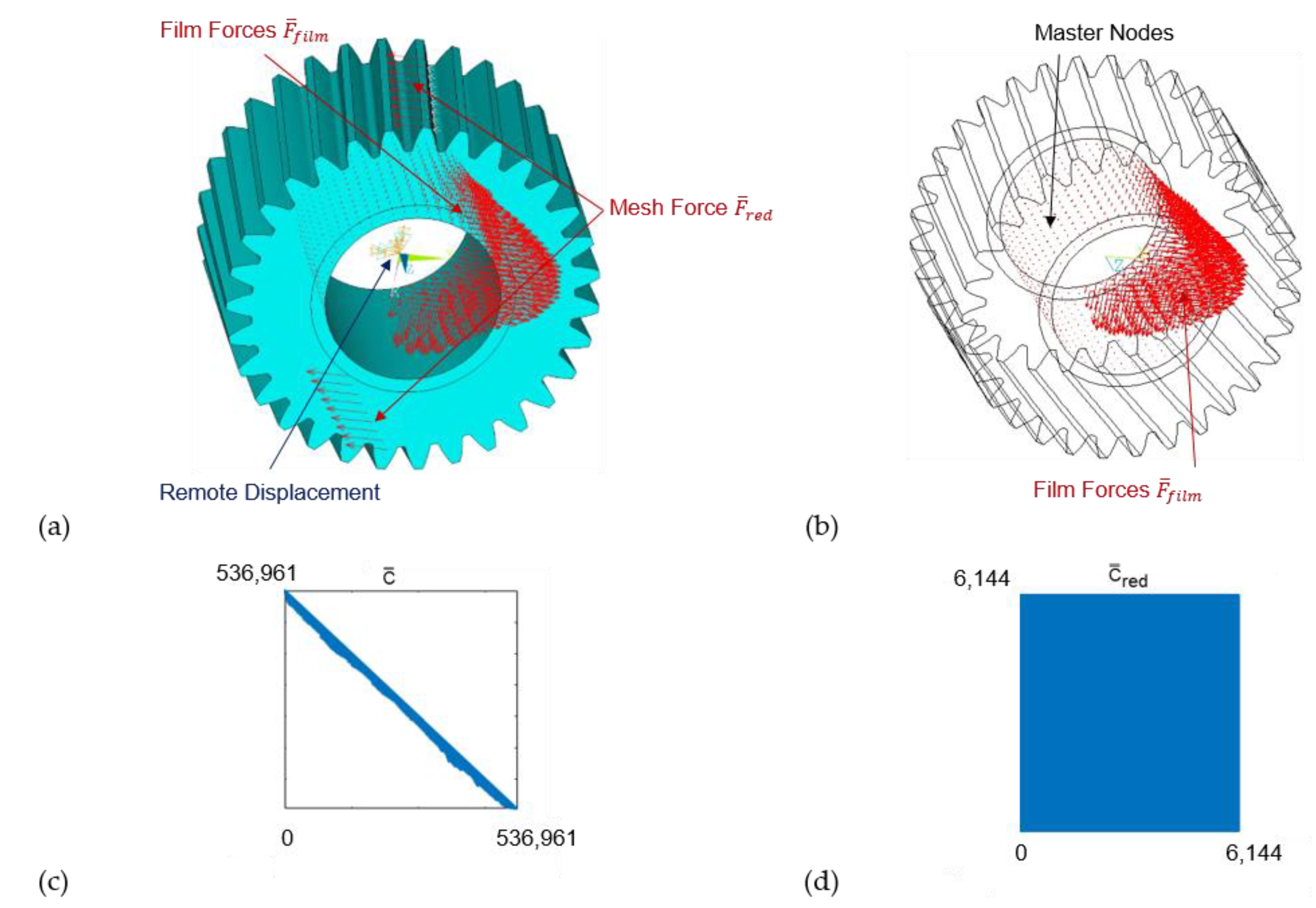
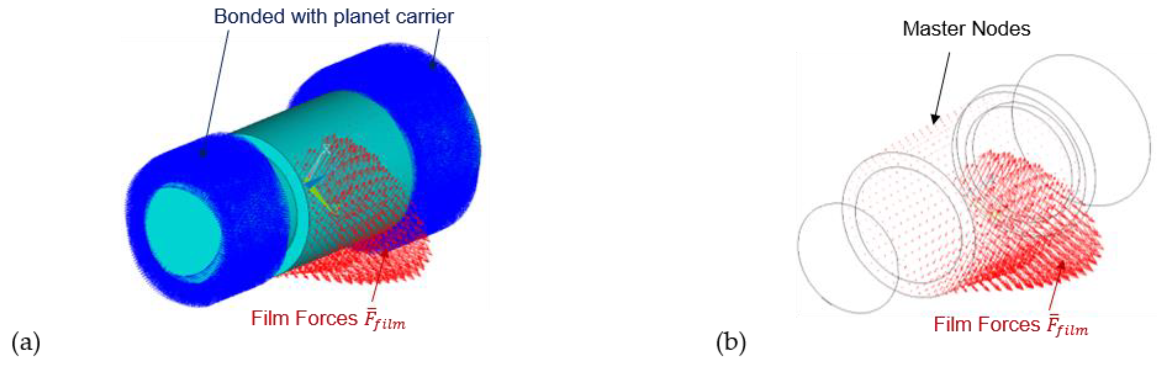
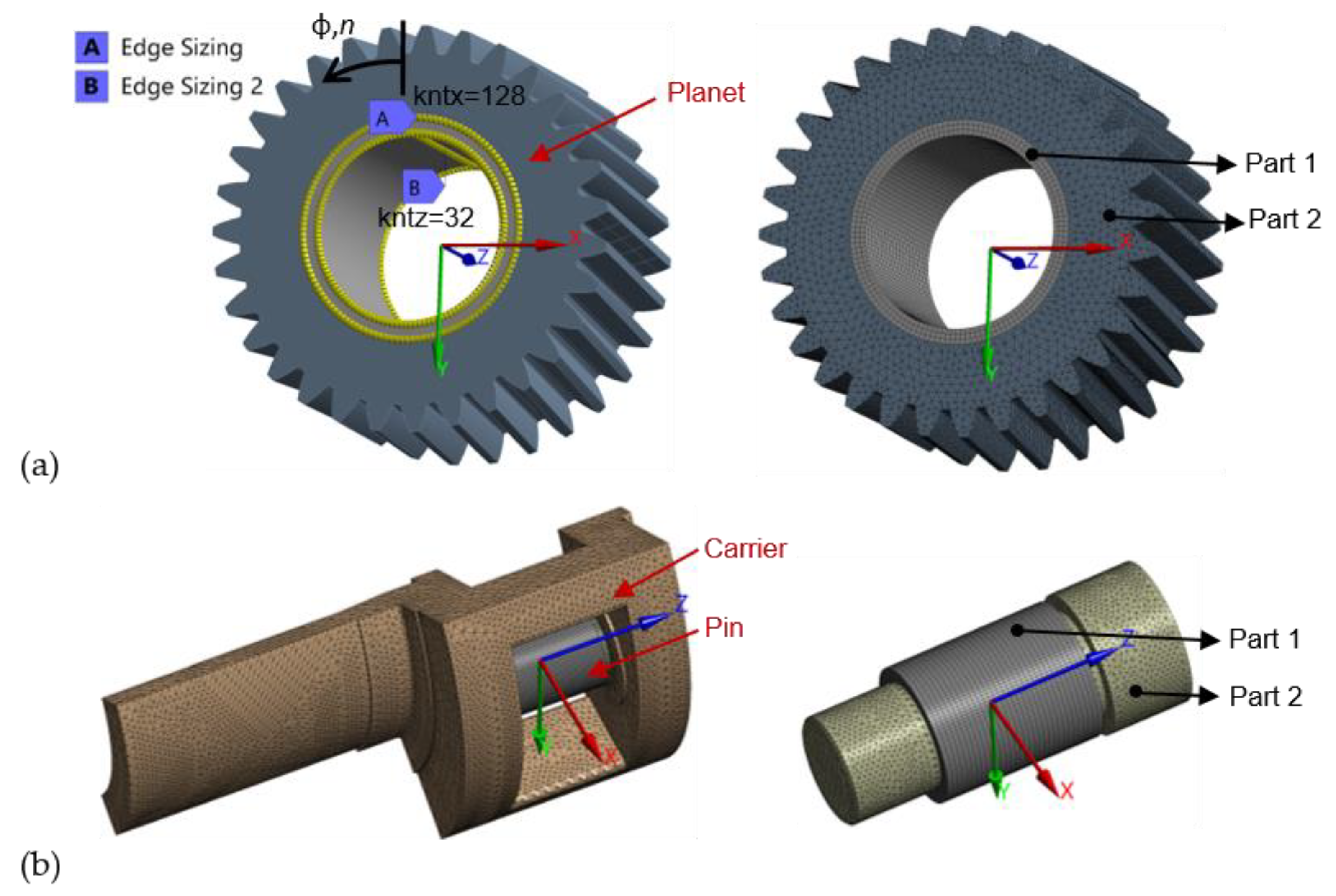
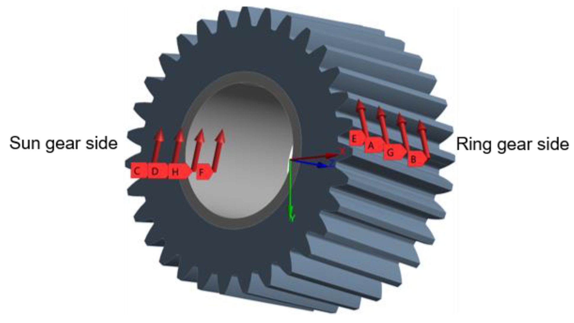
The modification of stiffness matrix dimensions due to the reduction procedure is explained for the planet model. The sliding surfaces of planet and pin are discretized with 128 elements in circumferential and 16 elements in axial directions. Due to condensation for reduced stiffness matrix, the number of degrees of freedom for the spatial deformable 178,987 nodes of the unreduced planet model is reduced from to of master nodes on the sliding surface. If only the nodes on the sliding surface are defined as master nodes, the reduced description of the structure is specific for a load distribution on the tooth flank, as shown in Figure 1a. However, the nodes on the tooth flank can be considered as additional master nodes, enabling the analysis of arbitrary load distributions of the mesh forces. This paper studies the impact of structure deformation on bearing operating behavior under nominal load. Consequently, a definition of master nodes on the sliding surface is sufficient. In addition, the influence of the deformation behavior of the planet carrier on bearing properties is also considered. In Figure 2a, the linear contact type ‘Bonded’ is defined at the contact surfaces between carrier and pin to ensure linearity of the entire model. This contact type merges the two structures and prohibits sliding or separation of its contact surfaces. Therefore, the model consisting of planet and pin behaves as a homogenous structure.

Figure 1.
(a) Complete FE-Model and (c) complete stiffness matrices, (b) reduced FE-Model and (d) reduced stiffness matrices for planet.

Figure 2.
(a) Complete and (b) reduced FE-Model for pin.
Based on the reduced structure properties introduced in Equation (4), deformation of the sliding surface is evaluated by Equation (5).
Herein, and are the reduced stiffness matrix and load vector, and is the film force representing the sum of hydrodynamic and asperity contact forces. For the planet, the force vector models the influence of the mesh forces on the sliding surface deformation, while this component does not exist for the pin. Assuming a constant shape of the load distribution on the tooth flank, can be scaled linearly by to consider different levels of mesh forces.
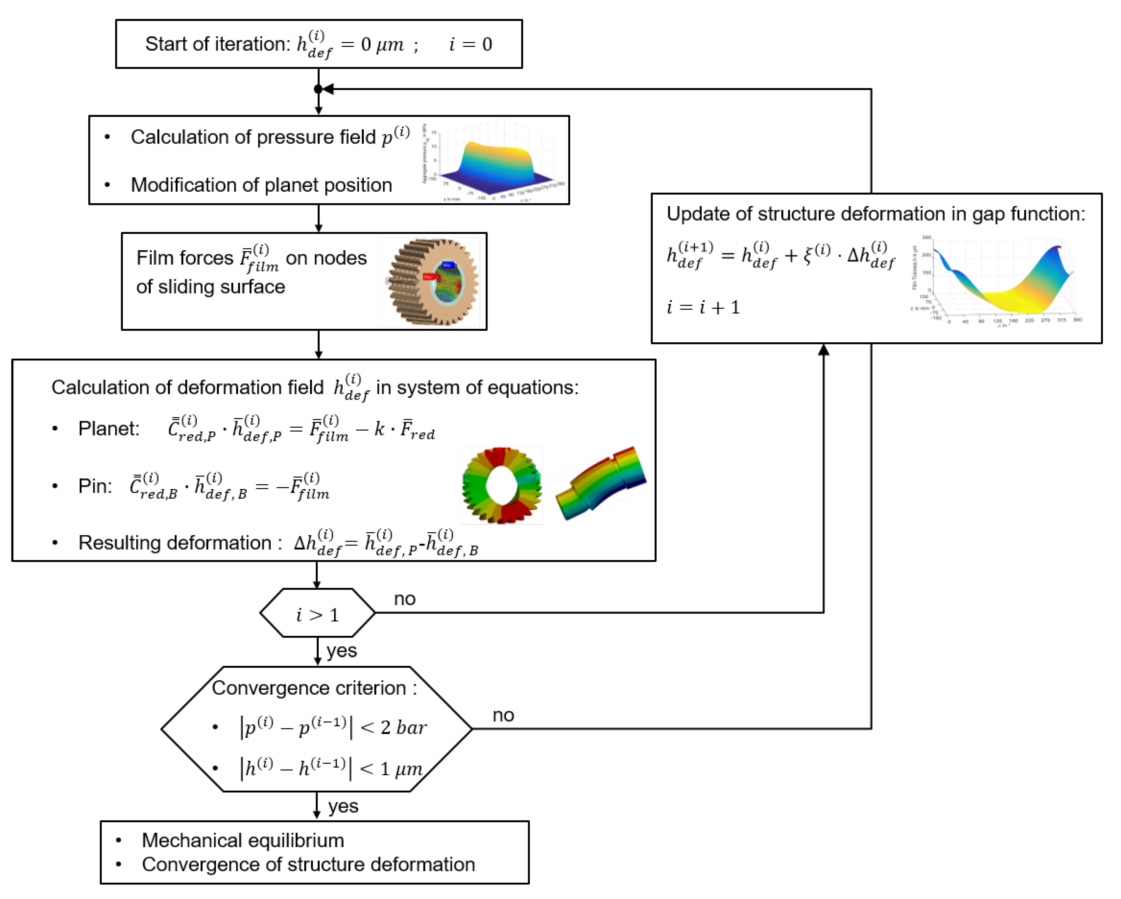
Figure 3 shows the algorithm for iterative calculation of the mechanical equilibrium for the planet gear bearing considering structure deformation. After the start of the iteration, the planet bearing code calculates the pressure field and the planet position for the undeformed gap contour according to the procedure explained in part I of this study [9]. Here, an equilibrium between the film forces and moments and the outer forces and moments, generated by the mesh load, exists. Predicted film forces are applied, on the nodes of the sliding surface of pin and planet, to analyze resulting deformation . This deformation is numerically damped by and considered in the gap function of the next fluid film analysis, according to Equation (6). These iterative steps repeat for the highly loaded system until maximum local difference of deformation, between two subsequent iterations, is less than 1 μm, and the maximum local difference of pressure remains below 0.2 MPa.
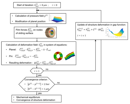
Figure 3.
Flowchart for consideration of deformation.
The factor varies between 0.01 and 0.2 in this study and is modified by a heuristic algorithm based on the convergence behavior of the calculation procedure.
2.2. Investigated Gear Set: Planet Gear Bearing
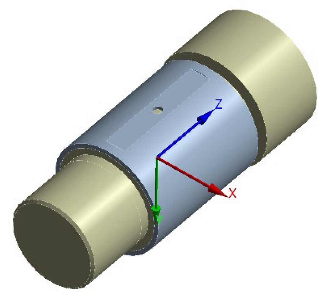
Table 1 includes the basic analysis parameters of the investigated planet gear bearing that equals the one studied in part I [9]. The values are in typical magnitude of planet gear bearings applied in 3 MW wind turbine gearboxes. Figure 4 depicts a pin with the sliding planet gear bearing. The oil supply pocket is located in the opposite direction of the bearing load.

Table 1.
Planet gear bearing parameters.

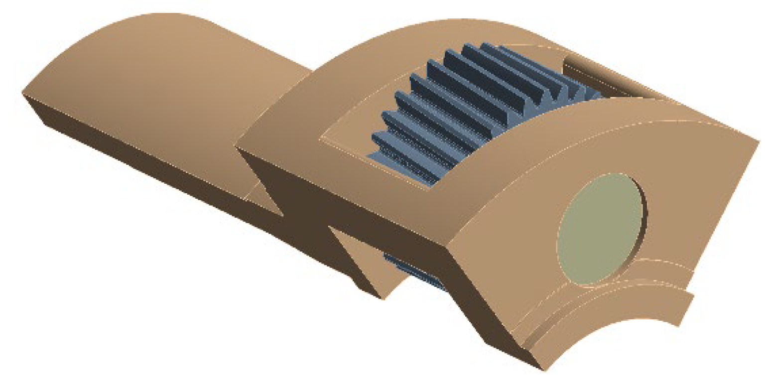
Figure 4.
CAD model of the pin with sliding planet gear bearing.
2.3. Investigated Gear Set: CAD Model and Material Properties
Figure 5 shows the CAD model of the investigated planetary stage. It consists of a carrier, five pins, and five planets with a helix angle β = 7°. Due to the periodicity of the system, one-fifth of the model in Figure 6 is utilized to reduce the required number of nodes in the subsequently derived structure analysis. Table 2 includes material properties of the planetary stage solid body components.
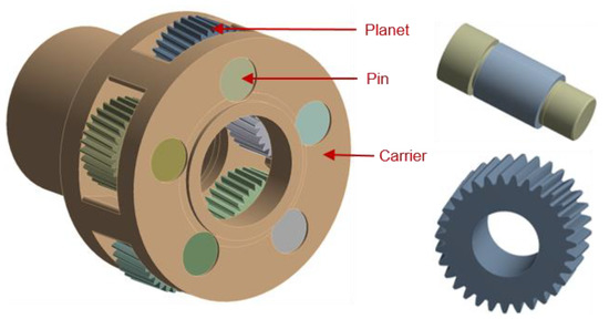
Figure 5.
CAD model of planet gear stage and its components.

Figure 6.
One-fifth of the CAD model of planet gear stage.
Table 2.
Material properties.
2.4. FEM Approximation for Structure Analysis: Meshing
Figure 7a shows that the planet is divided into two parts. The inner structure (part 1) features a cylinder geometry that can be well approximated by hexahedral meshes. The mesh of the outer structure (part 2) can be optionally set to a tetrahedral mesh. Both sub-structures are joint via a bonded contact to behave as a homogenous structure. The same method of mesh generation is applied to the pin shown in Figure 7b. Additionally, pin and carrier are merged by a bonded contact.

Figure 7.
Hexahedral mesh of sliding surface for planet (a) and pin with carrier (b).
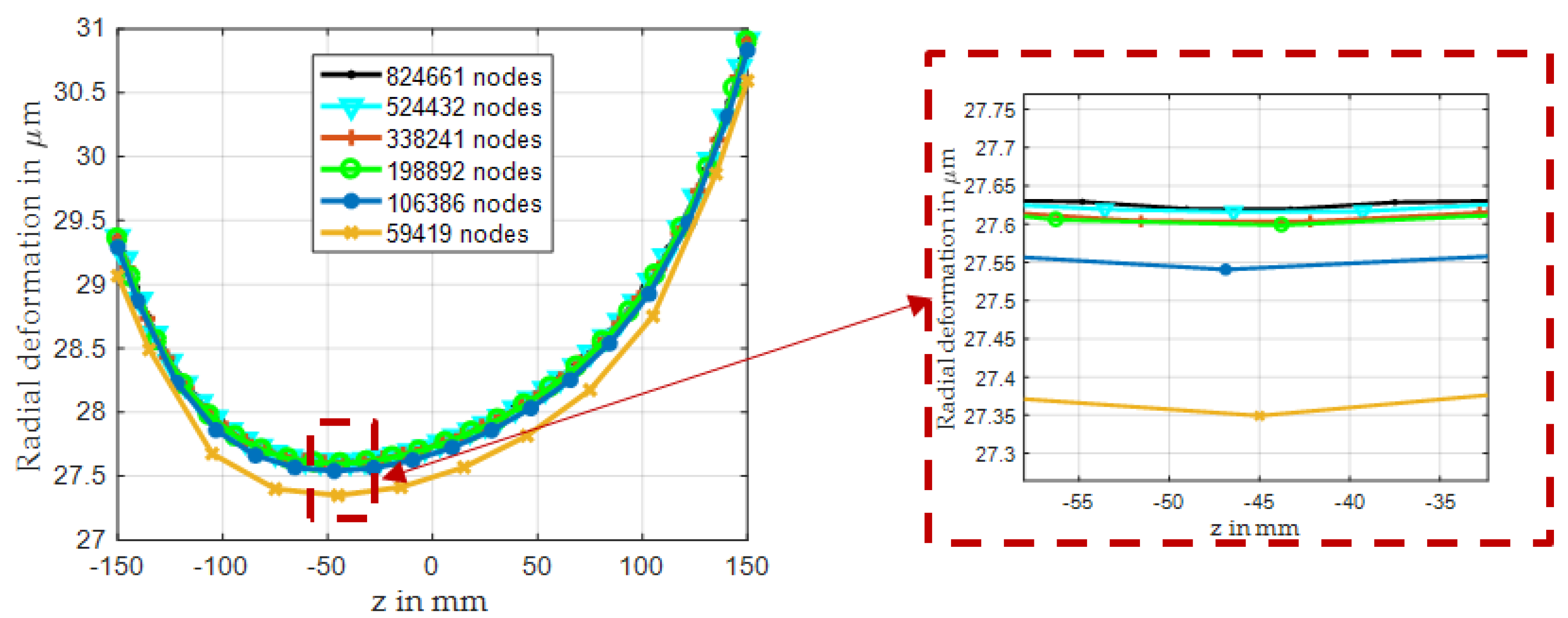
The position of the nodes on the sliding surface in FEM model matches the one of the film analysis to prevent interpolation uncertainties. For the following investigations, the sliding surface is discretized with 128 in circumferential and 32 elements in axial directions by using the hexahedral element type. The entire unreduced FE-model features 338,241 nodes. To prove independency of the results, due to level of discretization, the number of nodes is varied homogenously in all three space directions. Figure 8 shows predicted radial deformation of the sliding surface at the origin of the angular coordinate for the same load distribution on the sliding surface of the planet. Results indicate that maximum relative deviation of radial deformation, between two levels of investigated mesh density, is below 0.2% starting with the discretization chosen by the authors. Therefore, the impact of structure discretization on predicted results is expected to be below the remaining uncertainties of the entire simulation procedure.
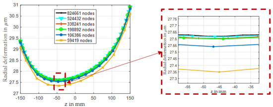
Figure 8.
Radial deformation at 0° degree across the bearing width for different mesh densities of the structure model.
2.5. FEM Approximation for Structure Analysis: Boundary Conditions and Mesh Forces
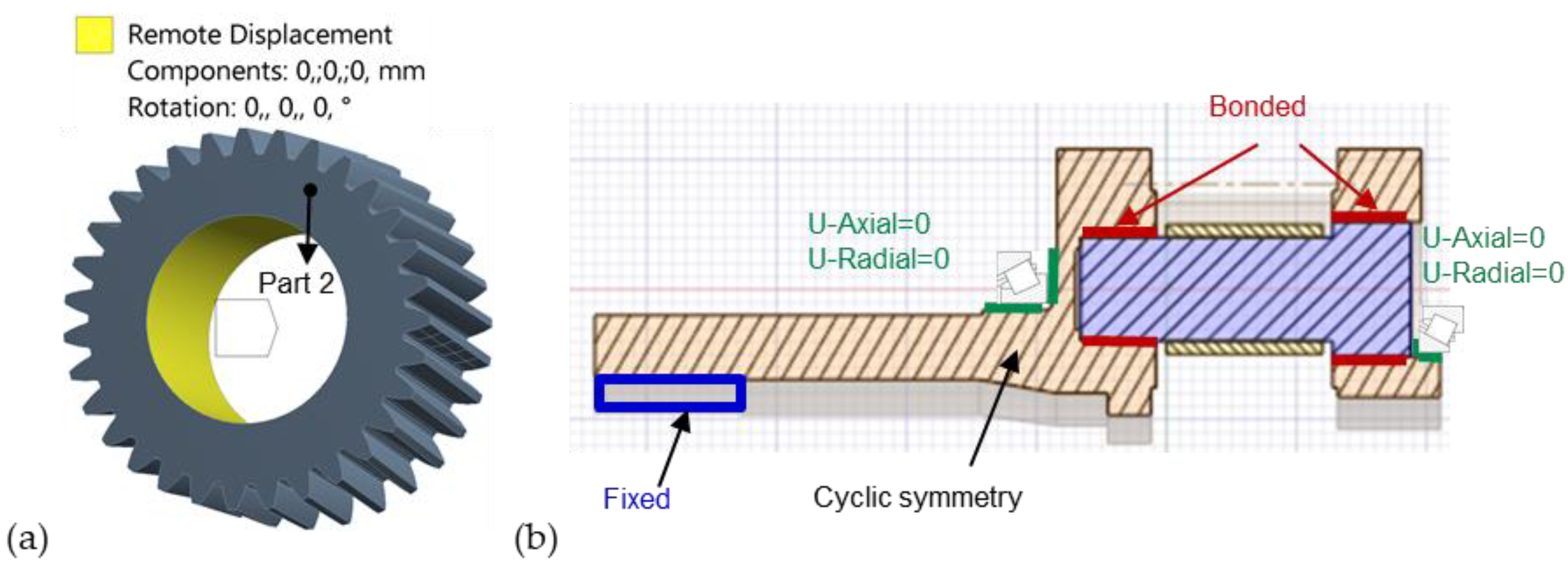
At the planet, a stationary mechanical equilibrium between the external mesh forces, the gravity forces, and the film forces exists. However, numerical differences between these forces remain and require a ‘Remote Displacement’ boundary condition, with 0 degrees of freedom, to prevent rigid body movement. In Figure 9a, this boundary condition is applied on the internal surface of part 2 of the planet. Figure 9b shows the bonded contact model for the connection between the planet carrier and planetary pins. Additionally, tapered rolling element bearings support both sides of the planet carrier and limit movement in radial and axial directions. The inner surface of the rotor side hub of carrier is fixed to provoke the twist deformation due to the applied driving torque. The two cross sections of the one-fifth model of the carrier feature cyclic periodicity boundary conditions.

Figure 9.
Boundary condition for planet (a) and pin with carrier (b).
Figure 10 shows the homogenous load distribution applied at 4 nodes on each tooth flank, and the total force components on each side of the tooth flank are included in the Table 3.
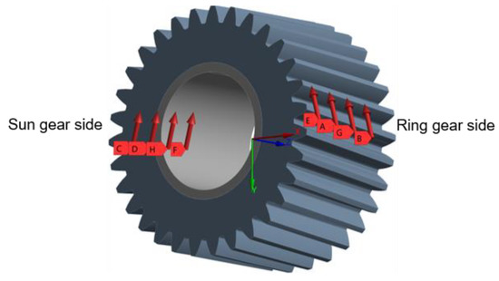
Figure 10.
Homogenous load distribution on each tooth flank.
Table 3.
Mesh load on the each tooth flank at nominal load conditions.
3. Results
3.1. Mesh and Bearing Loads
The relations between mesh forces and the investigated static bearing loads are comprehensively described in part I of this study. Considering the helix angle of the helical gear of 7°, according to Table 1, the nominal load case corresponds to a bearing force of Fsc = 900 kN and a moment load of Msc = 27.6 kNm. This load case exists for a relative input torque of Tr = 100%. According to the explanations in part I, bearing force and moment loads vary linearly with the relative input torque.
3.2. Verification of the Calculation Procedure
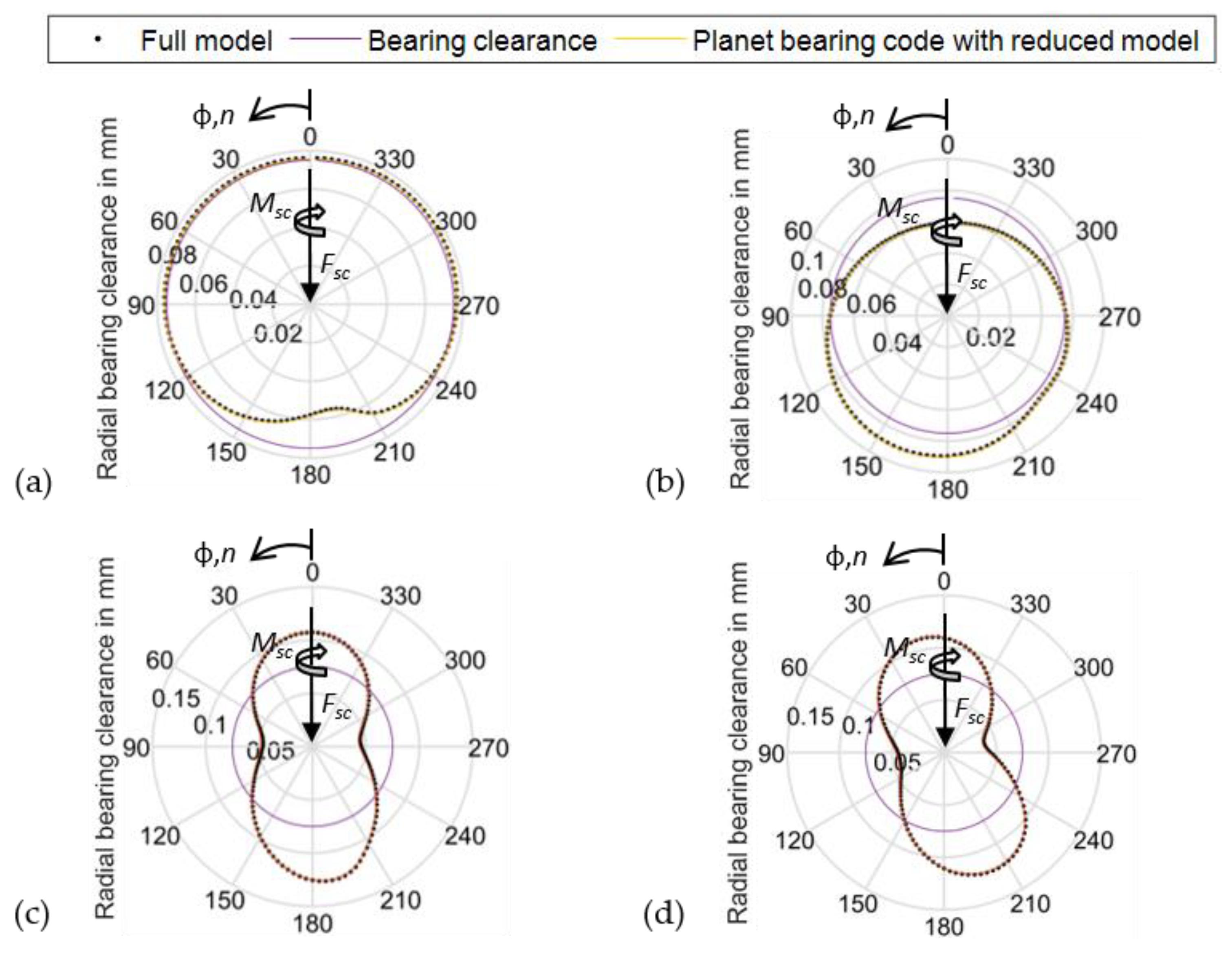
The procedure for consideration of planet and pin deformation, using a reduced structure model and its implementation in the planet bearing code, is verified by a comparison to predicted deformation results of the full, unreduced structure model. This study applies ANSYS for structure mechanical analyzes. Figure 11 shows the results of the deformation analysis with the full structure model in ANSYS and with the reduced model in the bearing code. In this case, the same exemplary pressure distribution is applied to both structures. Results at the center and the bearing end show very good agreement with a maximum deviation of 1.7 µm. Furthermore, the distribution of deviations that is not shown here features a harmonic shape and, therefore, indicates differences of predicted rigid body displacements without significant impact on gap contour and hydrodynamics. Consequently, these results verify the application of the reduced structure model, according to the procedure explained in Section 2.1.
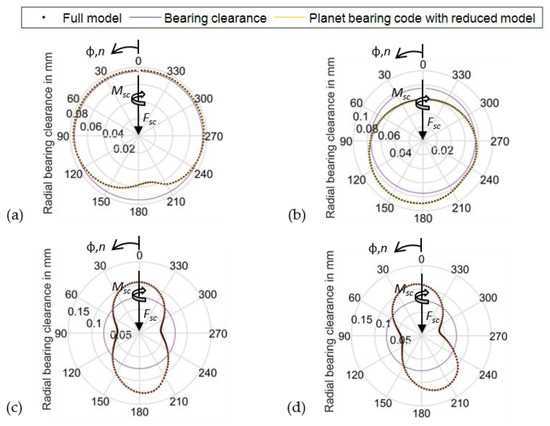
Figure 11.
Comparison of gap contour in the center of bearing z = −4.7 mm for (a) pin and (c) planet, and at the bearing edge z = −150 mm for (b) pin and (d) planet @ nominal operating conditions (npl = 30 rpm, Fsc = 900 kN, Tsup = 60 °C, psup = 0.2 MPa, Mbear = 27.6 kNm, β = 7°).
3.3. Deformation Behavior of Components
The general component deformation behavior, which is already introduced in Figure 11, is analyzed in more detail in this section. Figure 12 shows the bearing clearance, together with the deformed contour of pin and planet, at the bearing edge (z = −150 mm) and in the center of the bearing (z = −4.7 mm) under nominal operating conditions, according to Table 1. In addition to these deformed components, the resultant gap contour, modifying the shape of the lubricant gap, is depicted.
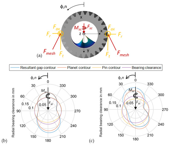
Figure 12.
Load conditions (a) and gap contour in the center of bearing z = −4.7 mm (b) and at the bearing edge, z = 150 mm (c) @ nominal operating conditions (npl = 30 rpm, Fsc = 900 kN, Tsup = 60 °C, psup = 0.2 MPa, Mbear= 27.6 kNm, β = 7°).
Figure 12 indicates three major characteristics of the deformation distribution for the two components, due to the load conditions in Figure 12a. First, the pin shows an indentation due to the pressure load that can be clearly seen by the comparison of the bearing clearance and the deformed pin contour in Figure 12a. Second, the pressure load provokes a twist of the components that is well recognizable for the planet, due to its higher flexibility. Maximum radial deformation in load direction is shifted from approximately 185°, in the center of the bearing, to 205° at its front end. Third, tangential and film forces pull the planet while the orthogonally acting radial forces push the planet. Consequently, the planet exhibits an oval shape that also dominates the resulting gap contour.
In addition, Figure 13 shows the variation of major and minor radial clearances at the front (z = 150 mm) and rear (z = −150 mm) of the planet gear bearing over the entire load range. The results show that the major and minor radial clearances exhibit nearly linear increasing and decreasing trends with rising load, respectively. Moreover, ovalization of the two lateral bearing ends is different. Here, the rear end shows a higher level due to larger maximum and lower minimum clearance. Figure 14 visualizes this property by the change of the total radial deformation, which represents the sum of radial planet and pin deformation, over the bearing width. Here, the major axis on the lateral bearing ends are shown, additionally, to express the previously described twist of the load zone in a three-dimensional view.
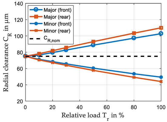
Figure 13.
Radial clearance of elastic calculation for variable relative loads (npl = 30 rpm, Fsc = 0–900 kN, Tsup = 60 °C, psup = 0.2 MPa, Mbear = 0–27.6 kNm, β = 7°).
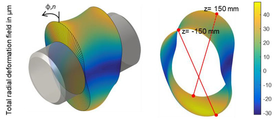
Figure 14.
Change of ovalization of the total radial deformation field over the bearing width @ nominal operating conditions (npl = 30 rpm, Fsc = 900 kN, Tsup = 60 °C, psup = 0.2 MPa, Mbear = 27.6 kNm, β = 7°).
Figure 15 depicts radial deformation of the full three-dimensional structure model for further analyses of deformation behavior and its major characteristics. Figure 15a visualizes the planet deformation with its significant ovalization that is previously explained. Figure 15b describes pin deformation. The global pin deformation is dominated by the twist of the two carrier cheeks, caused by the transmitted torque in the planetary stage. Therefore, the pin that is connected on both ends, by a crimp to the cheeks, exhibits an s-shape deformation clearly observable in Figure 15b.
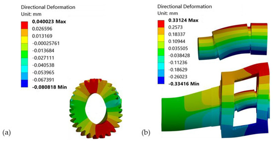
Figure 15.
Radial deformations of components of planet (a) and pin and carrier (b) in ANSYS @ nominal operating conditions (npl = 30 rpm, Fsc = 900 kN, Tsup = 60 °C, psup = 0.2 MPa, Mbear = 27.6 kNm, β = 7°).
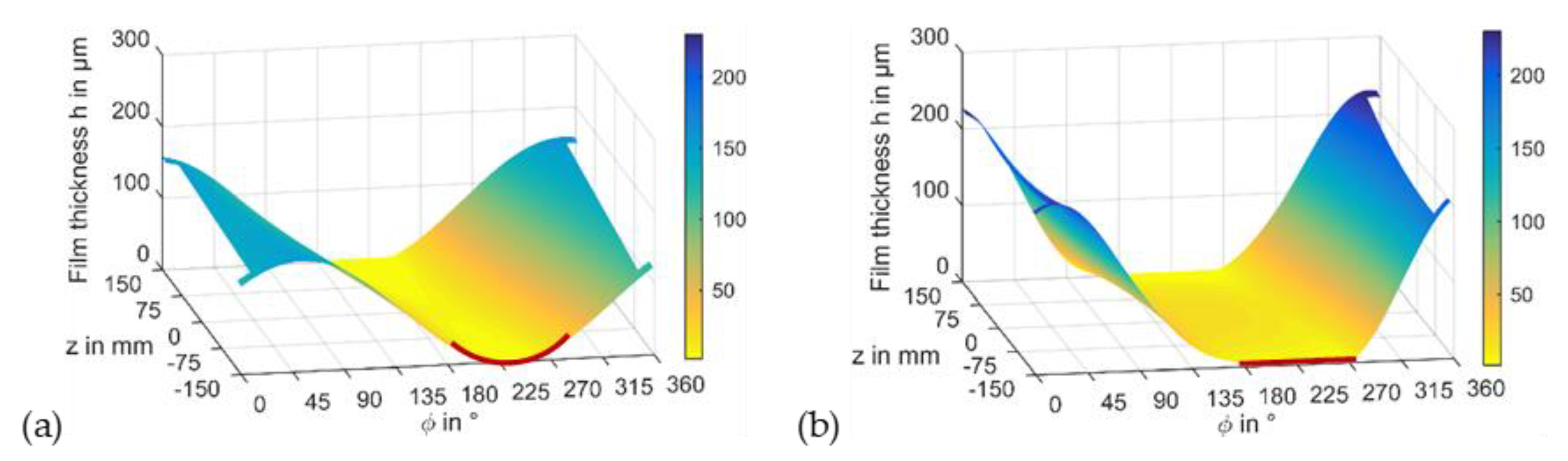
Figure 16 shows the comparison of the film thickness predicted by the rigid and the flexible calculation. Compared to the rigidly predicted film thickness in Figure 16a,b, the elastic calculation provides a nearly parallel film thickness with low gradients in circumferential direction of the loaded zone in Figure 16c,d. The red marks, in the side view in Figure 16a,c, as well as the top views in Figure 16b,d, give a deeper impact on this difference. This behavior is typical for highly loaded contacts and incorporate a decrease in the maximum pressure level.
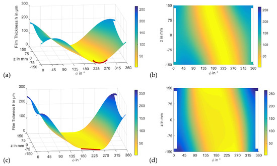
Figure 16.
Film thickness of rigid (a,b) and flexible calculation (c,d) @ nominal operating conditions with crowning #2 (npl = 30 rpm, Fsc = 900 kN, Tsup = 60 °C, psup = 0.2 MPa, Mbear = 27.6 kNm, β = 7°).
3.4. Impact of Axial Profiling Model on Bearing Considering Elastic Deformation of Components
The first part [9] of this study shows that an axial crowning #2, exhibiting a continuous parabolic shape among the bearing width, is suitable to reduce maximum pressure and increase minimum film thickness. In the next step, this measure is investigated considering elastic deformation. Figure 17 illustrates that comparable maximum pressures exist with, and without, crowning at nominal operation. This result is in contrast to the rigid one presented in [9], where essential differences are determined. In accordance with the rigid results, the crowning #2 provides an advantage. However, the maximum pressure of 23.6 MPa with crowning, in Figure 17b, is only 7.1% lower than the one without axial crowning. Again, the crowning provides a more homogeneous pressure profile in lateral direction.
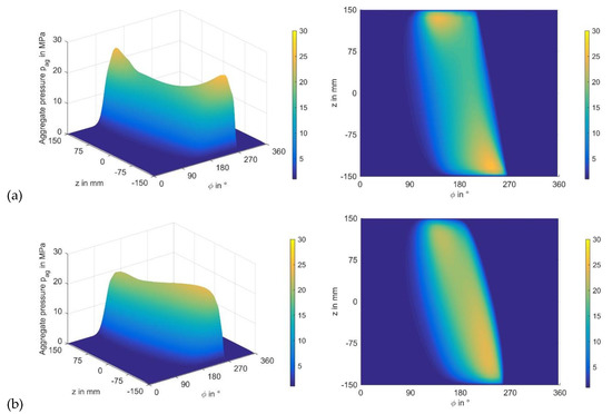
Figure 17.
Pressure distributions of elastic calculation at nominal operating conditions without crowning (a) and with crowning #2 (b) (npl = 30 rpm, Fsc = 900 kN, Tsup = 60 °C, psup = 0.2 MPa, Mbear = 27.6 kNm, β = 7°).
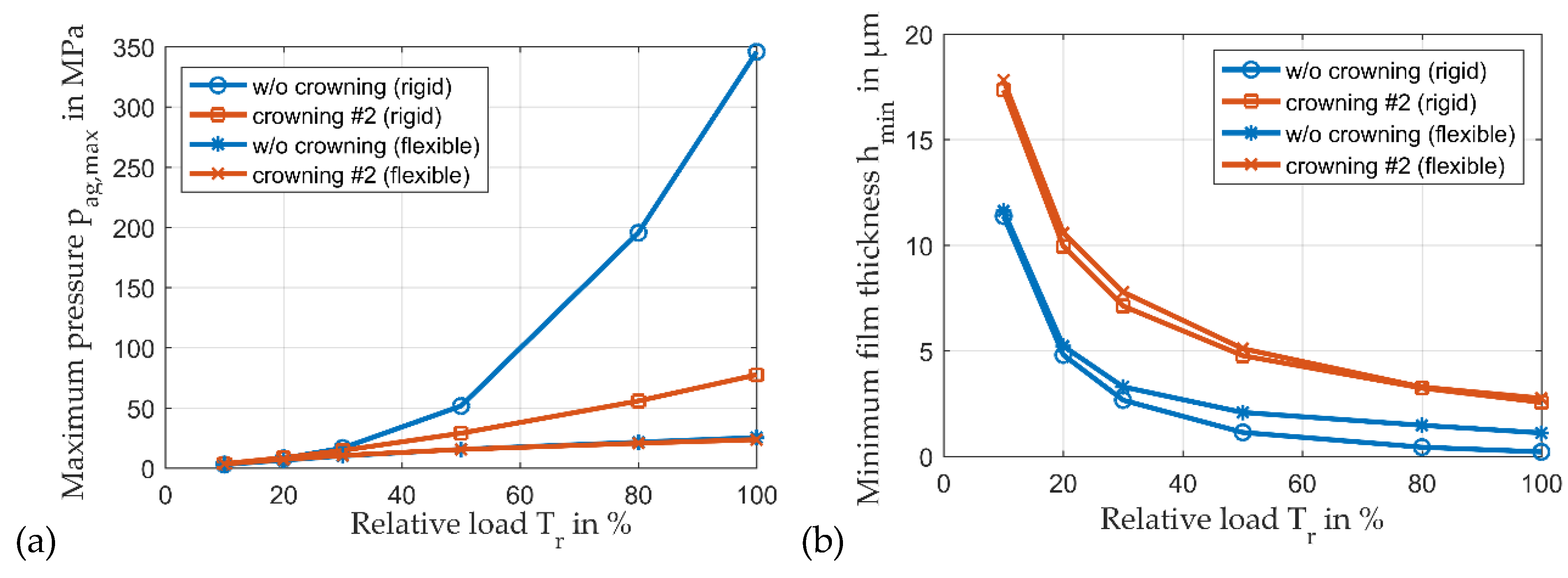
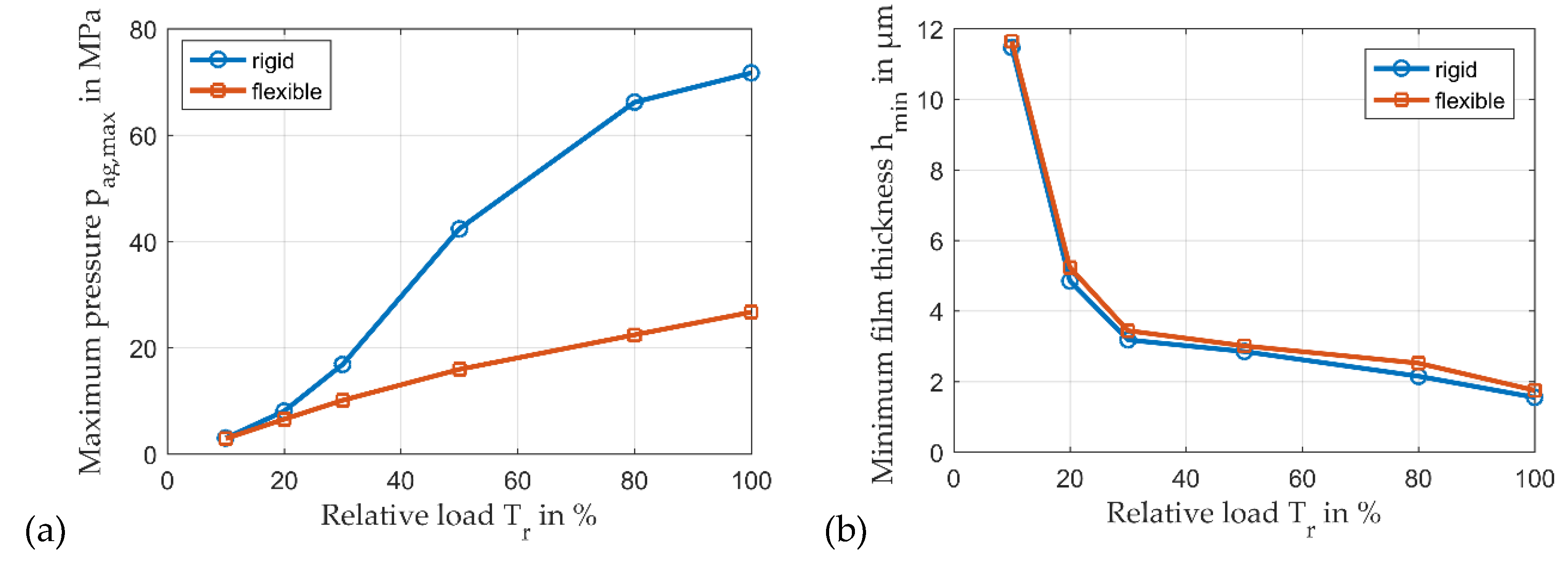
Figure 18 shows maximum pressure and minimum film thickness for rigid and flexible analyses for the entire speed range. The crowning #2 provides advantage in the entire load range with increasing minimum film thickness and decreasing maximum pressure. While the reduction in maximum pressure in Figure 18a is comparably low, as explained before, the rise of minimum film thickness Figure 18b is significant and underlines the importance of this measure for safe operation.
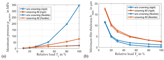
Figure 18.
Comparison of maximum pressure (a) and minimum film thickness (b) between rigid and elastic calculation for variable relative loads (npl = 30 rpm, Fsc = 0–900 kN, Tsup = 60 °C, psup = 0.2 MPa, Mbear = 0–27.6 kNm, β = 7°).
While results predicted under consideration of crowning show nearly pure hydrodynamic operation with maximum asperity contact pressures of pc < 0.04 MPa, significant deviations between the results for flexible and rigid geometries exist for constant clearance in axial directions. As shown in Figure 18b, minimum film thickness increases under consideration of deformation. Consequently, the intensity of mixed friction is reduced, and maximum solid contact pressure decreases, according to Figure 19a. Assuming a boundary coefficient of friction of µ = 0.03, to derive solid contact shear stress from solid contact pressure, a notable impact of asperity contacts on maximum temperature and frictional power loss can be observed, starting with a relative load of Tr = 50%, in Figure 19b.
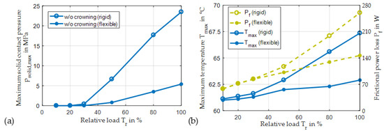
Figure 19.
Comparison of maximum solid contact pressure (a) and temperature and frictional power (b) between rigid and elastic calculation for variable relative loads without axial crowning (npl = 30 rpm, Fsc = 0–900 kN, Tsup = 60 °C, psup = 0.2 MPa, Mbear = 0–27.6 kNm, β = 7°).
3.5. Modification of the Lubricant Gap by Wear Considering Elastic Deformation of Components
To analyze the impact of flexibility on predicted wear distributions, rigid and flexible simulations are conducted for 560 h of operation. According to part I of this study, wear is evaluated according to Archard’s law with a wear coefficient of .
It is assumed that the softer material is located on the stator side, provoking a two dimensional variable distribution of wear on the sliding surface of the bearing that does not feature the axial crowning.
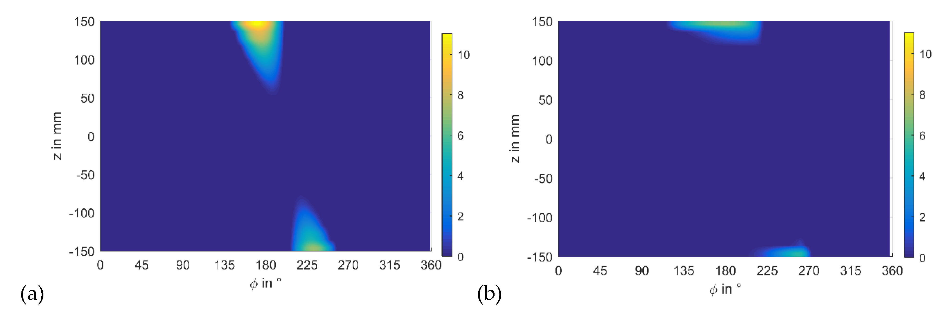
Figure 20 includes the wear distributions for the nominal load case. In comparison to the wear distribution predicted for rigid geometries, the flexible analysis shows three major differences. First, the entire wear level decreases and exhibits a reduction in wear height by approximately 40%. Second, the extent of the areas featuring wear significantly reduces in lateral direction and concentrates more on the bearing ends. Third, the angular span of the area with wear in a circumferential direction rises, due to the characteristic of the deformed lubricant gap, that shows a wider region of low film thickness, according to Figure 16c,d.
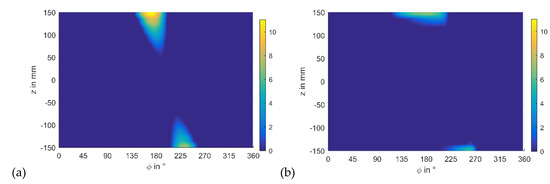
Figure 20.
Wear after 560 h run with rigid geometries (a) and under consideration of elastic deformations (b) at nominal operating conditions (npl = 30 rpm, Fsc = 900 kN, Tsup = 60 °C, psup = 0.2 MPa, Mbear = 27.6 kNm, β = 7°, t = 560 h, no axial crowning).
Maximum pressure, determined for the flexible planet gear bearing in Figure 21b, is only 26.7 MPa and is, therefore, approximately 38% of the one predicted for the rigid bearing that is reported, already, in part I [9] and shown in Figure 21a. However, in contrast to the rigid case, wear has no significant impact on maximum pressure, as film thickness modification concentrates on the lateral bearing end and has little influence on hydrodynamics. A comparison of Figure 17b or Figure 21b underlines this statement, as there is no qualitative difference of the pressure distributions. Additionally, Figure 21 illustrates the extent of the load region in circumferential direction, caused by elastic deformation and already described for film thickness, in Figure 16. Here, the two red lines enclosing the load region in the top view of each pressure distribution show a wider range of contact pressures in circumferential direction and a more homogenous distribution in lateral direction for the flexible case in Figure 21b than for the rigid case in Figure 21a.
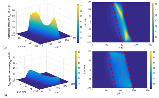
Figure 21.
Pressure distribution after 560 h with rigid geometries (a) and under consideration of elastic deformations (b) @ nominal operating conditions (np = 30 rpm, Fsc = 900 kN, Tsup = 60 °C, psup = 0.2 MPa, Mbear = 27.6 kNm, β = 7°, t = 560 h, no axial crowning).
Figure 22 shows the film thickness of rigid and elastic calculations for the worn bearing after 560 h. As expected, results are qualitatively comparable to the ones in Figure 16 with the exception of the extension of the loaded area, due to wear in the rigid case. The minimum film thicknesses of Figure 16 and Figure 22 are summarized in Table 4. By comparing rigid and elastic calculations, the elastic deformation of components have little impact on predicted minimum film thickness, whereas the characteristic of the lubricant gap significantly changes if the impact of deformation is considered.

Figure 22.
Film thickness of rigid calculation (a) and under consideration of elastic deformations (b) at nominal operating conditions without crowning after 560 h (npl = 30 rpm, Fsc = 900 kN, Tsup = 60 °C, psup = 0.2 MPa, Mbear = 27.6 kNm, β = 7°, t = 560 h, no axial crowning).
Table 4.
Minimum film thickness of rigid and elastic calculation at nominal operating conditions with crowning #2 or without crowning after 560 h.
Figure 23 shows the variation of maximum pressure and minimum film thickness over the entire load range for rigid and elastic calculations, considering wear after 560 h. The comparison with the unworn results from Figure 16 indicates that the wear process has a great impact on predicted maximum film pressure for rigid geometries by decreasing its value by almost 70%, while it modifies the flexible results less significantly, and maximum pressure remains nearly constant. However, for the same operating conditions, minimum film thickness increases from the theoretical value of 0.21 µm to 1.55 µm for the rigid analysis. Concordantly, a significant rise from 1.11 µm to 1.75 µm is predicted under consideration of flexible geometries. As this modification concentrates on the bearing edge, it has little impact on maximum pressure.
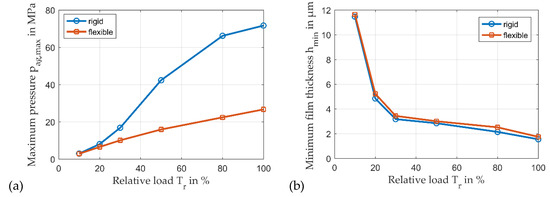
Figure 23.
Comparison of maximum pressure (a) and minimum film thickness (b) between rigid and elastic calculation for variable relative loads, without crowning, after 560 h (npl = 30 rpm, Fsc = 900 kN, Tsup = 60 °C, psup = 0.2 MPa, Mbear = 27.6 kNm, β = 7°, t = 560 h, no axial crowning).
4. Discussion and Conclusions
This paper introduces a time-efficient procedure for sliding planet gear bearing analysis, based on reduced structure models. The numerical procedure is verified by comparisons to co-simulation results, determined with an unreduced structure model of a planetary gear stage, with dimensions that are typical for wind turbine gearbox applications. Further structure analyses with this model provide an impact on deformation behavior of the bearing components caused by the specific load conditions of the helical gear. Under load, the planet exhibits a characteristic ovalization of its structure that twists in lateral direction. The pin deforms to an s-shape by the twist of the carrier cheeks it is connected to. Moreover, both planet gear bearing components show a deformation that provokes lower film thickness gradients in the loaded region. The modification of the lubricant gap, generated by this behavior, leads to an enlargement of the loaded area and a reduction in local load maxima. Consequently, consideration of structure flexibility is essential for quantitative sliding planet gear bearing analyses.
General tendencies of the impact of an axial crowning and wear on operating behavior match the ones predicted, based on the presumption of rigid bearing geometries, in part I [9] of this study. However, the magnitude of their influence changes significantly, as structure deformation modifies the shape of the lubricant gap in wide ranges. For the investigated cases of this study, consideration of structure flexibility provides lower maximum film pressures and higher minimum film thickness. This improvement of predicted operating behavior reduces the intensity of asperity contacts and of the wear derived from it. Therefore, results indicate that consideration of structure deformation is also important to predict wear-lifetime. Moreover, the modified operating behavior has to be taken into account to characterize the bearing as a component of the entire gear system in the design procedure. Here, the impact of the planet gear bearing properties on the gear mesh design represents an example. In summary, part I of this study indicates that different measures exist to optimize planet gear bearings, while part II additionally shows that a quantitative judgement about these measures requires a consideration of structure deformation, due to its high impact on predicted operating behavior.
The entire study uses a THD model that has been validated comprehensively for journal bearing applications. It is adapted to the planet gear bearing case, and the procedure for the consideration of structure deformation is verified by a full model structure analysis in a co-simulation. However, validation of the entire procedure is not possible yet.
Author Contributions
Conceptualization, methodology, T.H., H.D. and E.R.; software, T.H. and H.D.; investigation, writing, and visualization, T.H., H.D. and E.R.; supervision and funding acquisition, H.S. All authors have read and agreed to the published version of the manuscript.
Funding
This research was not supported by external funding.
Conflicts of Interest
The authors declare no conflict of interest.
References
- Jang, J.Y.; Khonsari, M.M. On the characteristics of misaligned journal bearings. Lubricants 2015, 3, 27–53. [Google Scholar] [CrossRef]
- Jang, J.Y.; Khonsari, M.M. Performance and characterization of dynamically-loaded engine bearings with provision for misalignment. Tribol. Int. 2019, 130, 387–399. [Google Scholar] [CrossRef]
- Sun, J.; Gui, C.; Li, Z.; Li, Z. Influence of journal misalignment caused by shaft deformation under rotational load on performance of journal bearing. Proc. Inst. Mech. Eng. Part J J. Eng. Tribol. 2005, 219, 275–283. [Google Scholar] [CrossRef]
- Sun, J.; Gui, C.; Li, Z. An Experimental Study of Journal Bearing Lubrication Effected by Journal Misalignment as a Result of Shaft Deformation Under Load. ASME J. Tribol. 2005, 127, 813–819. [Google Scholar] [CrossRef]
- Sander, D.E.; Allmaier, H.; Priebsch, H.H.; Reich, F.M.; Witt, M.; Skiadas, A.; Knaus, O. Edge loading and running-in wear in dynamically loaded journal bearings. Tribol. Int. 2015, 92, 395–403. [Google Scholar] [CrossRef]
- Lahmar, M.; Frihi, D.; Nicolas, D. The Effect of Misalignment on Performance Characteristics of Engine Main Crankshaft Bearings. Eur. J. Mech. A 2002, 21, 703–714. [Google Scholar] [CrossRef]
- Zhang, X.; Yin, Z.; Dong, Q. An experimental study of axial misalignment effect on seizure load of journal bearings. Tribol. Int. 2019, 131, 476–487. [Google Scholar] [CrossRef]
- Bouyer, J.; Fillon, M. Improvement of the THD performance of a misaligned plain journal bearing. J. Trib. 2003, 125, 334–342. [Google Scholar] [CrossRef]
- Hagemann, T.; Ding, H.; Radtke, E.; Schwarze, H. Operating behavior of sliding planet gear bearings in turbine gearbox applications—Part I: Basic relations. Lubricants 2021, in press. [Google Scholar]
- Desbordes, H.; Fillon, M.; Frene, J.; Chan Hew Wai, C. The Effects of Three-Dimensional Pad Deformations on Tilting-Pad Journal Bearings under Dynamic Loading. J. Tribol. 1995, 117, 379–384. [Google Scholar] [CrossRef]
- Hopf, G. Experimentelle Untersuchungen an Großen Radialgleitlagern für Turbomaschinen. Ph.D. Thesis, Ruhr University Bochum, Bochum, Germany, 1989. [Google Scholar]
- Hagemann, T.; Kukla, S.; Schwarze, H. Measurement and prediction of the static operating conditions of a large turbine tilting-pad bearing under high circumferential speeds and heavy loads. In Proceedings of the ASME Turbo Expo 2013, San Antonio, TX, USA, 3–7 June 2013. [Google Scholar] [CrossRef]
- Lahmar, M.; Ellagoune, S.; Bou-Saïd, B. Elastohydrodynamic lubrication analysis of a compliant journal bearing considering static and dynamic deformations of the bearing liner. Tribol. Trans. 2010, 53, 349–368. [Google Scholar] [CrossRef]
- Prölß, M. Berechnung Langsam Laufender und Hoch Belasteter Gleitlager in Planetengetrieben unter Mischreibung, Verschleiß und Deformationen. Ph.D. Thesis, Clausthal University of Technology, Clausthal-Zellerfeld, Germany, 2020. [Google Scholar]
- Profito, F.J.; Zachariadis, D.C.; Dini, D. Partitioned Fluid-Structure Interaction Techniques Applied to the Mixed-Elastohydrodynamic Solution of Dynamically Loaded Connecting-Rod Big-End Bearings. Tribol. Int. 2019, 140, 105767. [Google Scholar] [CrossRef]
- Habchi, W.; Eyheramendy, D.; Vergne, P.; Morales-Espejel, G. A full-system approach of the elastohydrodynamic line/point contact problem. J. Tribol. 2008, 130, 021501. [Google Scholar] [CrossRef]
- Oh, K.P. The numerical solution of dynamically loaded elastohydrodynamic contact as a nonlinear complementarity problem. J. Tribol. 1984, 106, 88–95. [Google Scholar] [CrossRef]
- Craig, R.; Roy, R.; Bampton, M.C.C. Coupling of substructures for dynamic analyses. AIAA J. 1968, 6, 1313–1319. [Google Scholar] [CrossRef] [Green Version]


Publisher’s Note: MDPI stays neutral with regard to jurisdictional claims in published maps and institutional affiliations. |
© 2021 by the authors. Licensee MDPI, Basel, Switzerland. This article is an open access article distributed under the terms and conditions of the Creative Commons Attribution (CC BY) license (https://creativecommons.org/licenses/by/4.0/).