Abstract
In this work, the influence of powder reuse up to three times on directed energy deposition (DED) with laser processing has been studied. The work was carried out on two different gas atomized powders: a cobalt-based alloy type Stellite® 21, and a super duplex stainless steel type UNS S32750. One of the main findings is the influence of oxygen content of the reused powder particles on the final quality and densification of the deposited material and the powder catch efficiency of the laser deposition process. There is a direct relationship between a higher surface oxidation of the particles and the presence of oxygen content in the particles and in the as-built materials, as well as oxides, balance of phases (in the case of the super duplex alloy), pores and defects at the micro level in the laser-deposited material, as well as a decrease in the amount of material that actually melts, reducing powder catch efficiency (more than 12% in the worst case scenario) and the initial bead geometry (height and width) that was obtained for the same process parameters when the virgin powder was used (without oxidation and with original morphology of the powder particles). This causes some melting faults, oxides and formation of undesired oxide compounds in the microstructure, and un-balance of phases particularly in the super duplex stainless steel material, reducing the amount of ferrite from 50.1% to 37.4%, affecting in turn material soundness and its mechanical properties, particularly the hardness. However, the Stellite® 21 alloy type can be reused up to three times, while the super duplex can be reused only once without any major influence of the particles’ surface oxidation on the deposited material quality and hardness.
1. Introduction
One of the most promising metal additive manufacturing (AM) technologies for large and multimaterial components is directed energy deposition and blown metal powder (DED-LB/M powder), whose acronym has recently been established in the ASTM 52900 standard guidelines [1], and which is also known as Laser Metal Deposition (LMD) in the industrial sector. The main barrier to the adoption of DED-LB/M powder is the efficiency of the material deposition, because due to the nature and the complex dynamics of the process, not all of the powder that is dispensed through coaxial and discrete nozzles and then interacts with the laser beam is melted and transformed into metal after deposition, so a percentage of the feedstock material (in this case powder) is wasted. One way to minimize the impact of the loss of the unmelted material is to study how to confine its disposal in the manufacturing cell or machine, collect it, dry it, sieve it, and reuse it for further use in a subsequent manufacturing batch. However, one of the drawbacks in the case where the process is carried out in an uncontrolled atmosphere (e.g., workstations/cells open to the atmosphere), is the surface oxidation of the powder and the change of particle morphology, in which some partially melted particles join other unmelted particles in a non-controlled manner, and therefore do not have the same size, morphology and flowability as the virgin particles that have not been used. There is also a shortage of reports in the literature on how the reuse of the collected post-process powder influences the microstructure, quality and properties of certain non-common materials deposited with reused powder.
Recently, some research papers have been published showing new methodologies for the recycling and reuse of powder collected after additive manufacturing by DED-LB, among which are the studies conducted with austenitic stainless steels by Gutjahr et al. [1] and Terrassa et al. [2]. Gaining new knowledge on how to reuse metal powder in DED-LB/M and how its reuse influences the quality of fabrications in SS 316L has also been studied by Li et al. [3]. Interesting results of the environmental impact assessment and sustainability of the powder feedstock were studied by Verdi et al. [4] and Joju et al. [5]. In other metal AM technologies like powder bed fusion with laser beam (PBF-LB/M), more abundant studies are available in the literature [6,7,8]. A review paper has recently been published highlighting the main challenges associated with powder recycling, such as maintaining a uniform particle size distribution and shape for reuse, contamination management and mitigation of the main degradation effects of repeated powder use, such as particle deformation, contamination, oxide deposits, fragmentation, wear, sintering, dealloying, and surface oxidation [9].
In this study, two different alloys were evaluated, Stellite® 21 type alloy and super duplex stainless steel. According to the literature review, both alloys are not reported in DED-LB powder reuse studies and scientific reports published. Cobalt-based alloys are commonly used in the DED-LB process for hardfacing coatings and manufacturing. They are recommended for applications involving wear, galling or corrosion and retain these properties at high temperatures. They have a wide range of applications; for example, Stellite® 6 is a common material for the seat surface enhancement of various control valves, while Stellite® 21 is often used for valve trims under high-pressure steam and harsh conditions [10]. Stellite® alloy compositions have also been used to remanufacture components [11,12], for example, rail components [13]. Due to its good sliding wear and impact resistance, these alloys have been widely used in the building up and repairing of forging or hot stamping die components [14]. Stellite® 21 is used in applications that require high wear resistance, as well as retaining these properties at high temperatures. The hardness of the material is directly related to its wear resistance. This is why it is important that the hardness and performance of the material is maintained throughout the different powder reuse cycles.
On the other hand, the super duplex stainless steels have an austeno-ferritic microstructure with an average fraction of each phase of approximately 50 wt.%. This duplex microstructure improves simultaneously the mechanical properties and corrosion resistance. Welding of these steels is often a critical operation [15]. The second generation of super duplex stainless steels (SDSS) such as type UNS S32750 (DIN 1.4410/Sandvik SAF2507) is increasingly being used in oil and gas and petrochemical applications because of its good corrosion resistance and high strength due to its dual phase austenite/ferrite microstructure [16]. Recently, a high interest in the DED-LB processing of SDSS has been observed. Authors like Jiang et al. [17], Iams et al. [18,19] and Brázda et al. [20] have published their research work with type UNS S32750 super duplex stainless steel and DED processes, giving their deep analysis and conclusions regarding the austenitic formation mechanisms, duplex microstructure balance and understanding, mechanical properties obtained, and potential heat treatments to be applied in this additively manufactured material.
Both materials addressed in this study are expensive in terms of their cost per kg or powder and their reuse in the DED-LB process makes good sense, in particular, for metal AM of medium to large parts. The aim of our research work is to study the influence of powder reuse on particle morphology, particle surface oxidation, internal defectology, microstructure and mechanical properties. This was done by collecting unmelted powder particles after processing with DED-LB (LMD) up to three successive times, with no use of virgin powder or mixing, and applying a specific methodology for reuse involving sieving and drying in the same storage canister. In doing so, we aim to provide the scientific community and industry with detailed technical and practical knowledge of the reuse of these two very different families of materials processed by laser using DED process.
2. Materials and Methods
This section summarizes all feedstock materials, microstructural characterization procedures, hardness testing equipment, laser material processing equipment, and methods that were used in the experimental work conducted.
2.1. Materials Characterization—Equipment and Methods Used in This Work
In this research work, two metal alloys were selected for the study, a cobalt-based alloy type Stellite® 21 and a super duplex stainless steel. The macro and microstructural analysis of the Super Duplex samples was carried out using light optical microscopy (LOM) at different magnifications (from 100× to 1000×) with an Olympus GX51 optical microscope (Shinjuku City, Japan) with an image acquisition system via digital camera. The chemical etching in the case of the SDSS was carried out using a manual etching with Beraha’s reagent (20 mL HCl + 100 mL H2O + 1 g K2S2O5) for 12 s. For more advanced studies in the microstructure, a field emission scanning electron microscope (FESEM) Zeiss Ultra Plus model (Oberkochen, Germany) equipped with an X-ray detector from Oxford instruments (X-Max) (Abingdon, UK) was also used. The area fraction of the main phases (in percentage) was quantified by making measurements via image analysis from the micrographs. In this case, five LOM images were taken at 200× magnification of different areas of the central part of the cubes manufactured, and then the images were binarized to contrast each phase, and the area represented by each phase was thereafter measured. The method used to quantify the austenite and ferrite phases is based on determining the volume fraction by systematic manual counting of points in the analysed area of the cross-section in the samples studied, following the guidelines of ASTM E562-19 [21]. Microhardness Vickers measurements were taken in an EmcoTest DuraScan durometer (Kuchl, Austria) using a load of 100 g (HV0.1 scale).
The metallurgical characterization of Stellite® 21 powder and manufactured samples was based on light optical microscopy (LOM) using a Leica Microsystems microscope (Wetzlar, Germany). Microhardness measurements were carried out by a Beortek Future-Tech FM700 Vickers hardness tester (Erandio, Spain), with a load of 500 g (HV0.5 scale). To identify the morphology of the powder and microstructure analysis in as-built cube samples, a Zeiss Ultra Plus FESEM (Oberkochen, Germany) was used for the analysis and examination. All manufactured samples were cut transversally, ground, polished and chemically etched with nitro-hydrochloric acid for variable duration (from 5 to 30 min).
For the rigorous chemical composition measurements carried out for each element in both alloys including the oxygen content, different techniques were employed. Carbon and sulfur measurements were determined by an Automatic Combustion Analyzer and infrared detection, using the CS 744 procedure based on ASTM E1019-18 guidelines [22], while oxygen content was determined using the ON 736 procedure based on ASTM E1019-18 [22] for both the Stellite® 21 and for super duplex SS. Remaining elements were measured using the Inductively Coupled Plasma Optical Emission spectroscopy (ICP-OES) technique. This is a multi-elemental analysis technique. The sample must be introduced into the equipment as a liquid, so it is necessary to perform a prior digestion of the sample using a Thermo Scientific Icap 7400 V (Waltham, MA, USA). The procedure used is applicable for nickel-based and cobalt-based materials like the Stellite® 21 type alloy. For the remaining elements in super duplex stainless steel, ICP-OES technique was also used but following the specific procedure indicated in the UNE-EN 10361:2016 standard [23].
2.2. Feedstock—Virgin Powders Characterization
In this work, two commercial gas-atomized powders were used. One was the super duplex stainless steel type SAF 2507 (UNS S32750) manufactured by Sandvik Osprey®. Powder particles were sieved after atomisation to achieve a particle size of +45–90 µm according to the certificate provided by the manufacturer. The chemical compositions reported by the powder manufacturer are shown in Table 1.

Table 1.
Chemical composition of powder batch used in the study (manufacturers certificate).
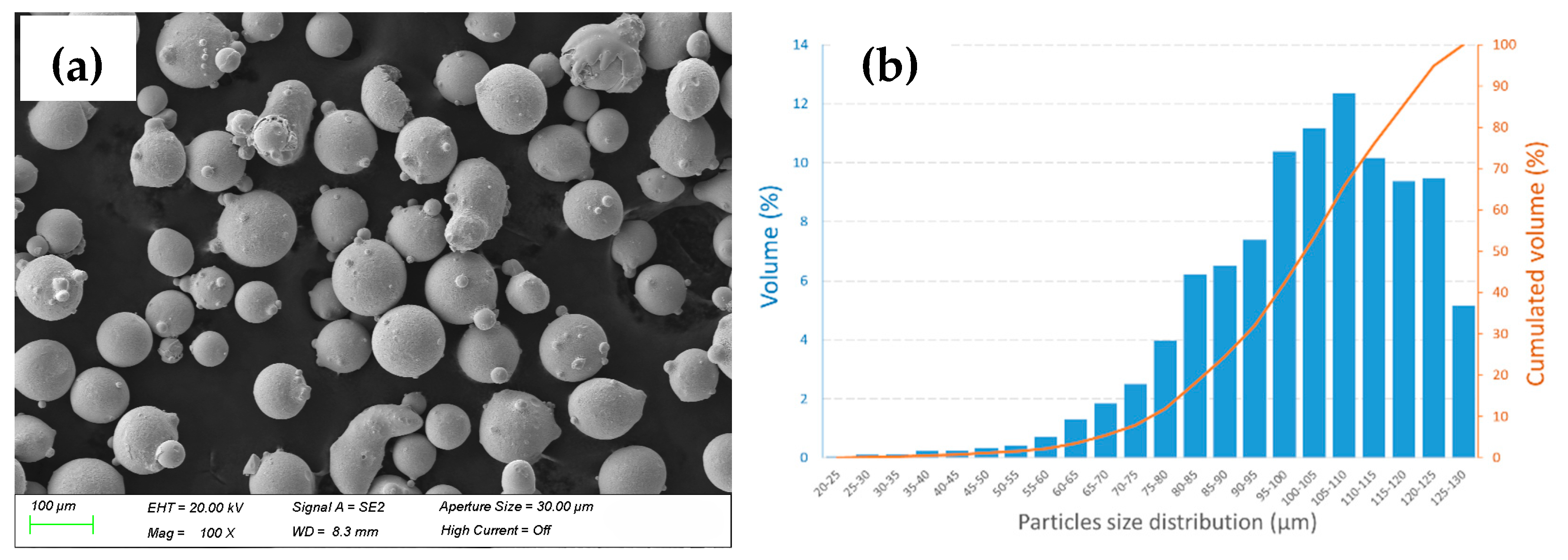
As a feedstock material quality check procedure, the powder particle batch was characterized and analysed using LOM and FESEM images. The particles’ morphology is shown in the FESEM micrographs of Figure 1a, and the calculated particle size distribution (PSD curve) is shown in Figure 1b. The particles showed a spherical shape, a morphology commonly obtained from the gas atomization procedure in their manufacturing. After the image analysis of the particles, the results revealed 10% by volume of the particles presented a size less than 56.51 µm in diameter; 50% of the particles were less than 77.6 µm in diameter; and a cumulative 90% by volume of the powder particles had a diameter less than 94.57 µm. As shown in Figure 1b, the particle size distribution is almost normal, like a gaussian distribution.
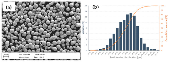
Figure 1.
Characterization of SAF 2507 virgin powder particles. (a) FESEM micrographs (200× and SE2 mode) and (b) histogram of the particle size distribution (PSD).
The second commercial gas-atomized cobalt-based powder used was a Stellite® 21 type alloy powder from Oerlikon (Schwyz, Switzerland) (Metco 1221A), with a particle size of +45–125 µm according to the certificate provided by the manufacturer. It is a little larger in size and coarser than the other powder, and the particle size distribution seems to have a non-gaussian distribution (see Figure 2b). The chemical composition reported for this Stellite® 21 type alloy powder is also shown in Table 1.
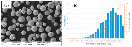
Figure 2.
Characterization of Stellite® 21 virgin powder particles. (a) FESEM micrographs (100× and SE2 mode) and (b) histogram of the particle size distribution (PSD).
2.3. Laser Material Deposition—Equipment and Experimental Set-Up
The super duplex stainless steel powder was processed by LORTEK using a robotic LMD cell equipped with a 6-axis Fanuc robot arm and a 2-axis positioner table. A solid-state 5 kW disc laser source (Trumpf TruDisk 6002, Ditzingen, Germany) operated in continuous wave (CW) mode with a wavelength of 1030 nm was also used. The laser beam is guided through an optic fibre of 400 µm. The configuration of the LMD robotic station includes a fixed optic head (Trumpf BEO D70-90°, Ditzingen, Germany) with collimation/focal length of 200/200 mm. For powder delivery, the LMD station has a twin powder feeder with two 5 L heated hoppers (Oerlikon-Metco Twin 150, Wohlen, Switzerland) and a 3-jet discrete nozzle (3-Jet-SO16-F manufactured by FhG ILT, Aachen, Germany). Argon was used as protective (8.5 L/min) and carrier gas (2 L/min flow at 2 bar) for powder particles delivery.
The manufacturing and study of Stellite® 21 samples were performed in TEKNIKER (Eibar, Spain) facilities and equipment with an LMD robotized cell, consisting of an optical head (Precitec YC50, Gaggenau, Germany) with collimation/focal length of 200/200 mm and a 3-jet powder nozzle cladding head (FhG ILT, Aachen, Germany) attached to an industrial 6-axis robot arm (ABB, Zurich, Switzerland) and a CW 2 kW laser source (IPG YLS-2000-CT-Y17, Burbach, Germany). The laser beam is guided through a 600 µm diameter optical fibre. The powder was fed during the deposition process by means of a powder feeder (Sulzer-Metco Twin 10C, Wohlen, Switzerland). Argon was used as shielding (15 L/min) and powder carrier gas (8 L/min flow at 2.8 bar).
2.4. Manufacturing Process, Powder Collection and Reuse Methodology
The very first step is to prepare a series of C45 steel base plates and by grinding them on both sides, ensuring parallelism and flatness. In this way, all the manufacturing cycles performed maintain the same distance between the nozzle and the part and the initial surface finish of the build plate substrate. Subsequently, each cycle consists of manufacturing a series of prismatic specimens by DED-LB (LMD) in an uncontrolled atmosphere, under normal conditions of pressure and temperature. The specimens’ sizes were 20 × 20 × 10 mm3 (16 layers) cubes for super duplex builds and 15 × 15 × 10 mm3 (14 layers) cubes for Stellite® 21 builds, repeating the necessary fabrications to obtain enough residual powder to manufacture samples in the following cycles with powder re-used. In addition, a single track is also deposited for each cycle as a reference track for dilution, height and width measurements.
During the DED-LB process, the non-deposited powder was collected using a collecting tray. This collecting tray is cleaned with isopropyl alcohol before each cycle to avoid cross-contamination with powder from other cycles. Once collected, the powder is manually collected and transferred to a suitable hermetically sealed container for storage (with two silica bags inside) until the next manufacturing and sieving cycle. The sieving of each cycle is carried out after the manufacturing of all the test specimens. The objective is to sieve the collected powder to remove impurities, spatter or clusters of adhered particles, whereby particles that are too fine or too coarse are separated, adjusting the particle size to a typical Laser DED distribution +53–150 µm.
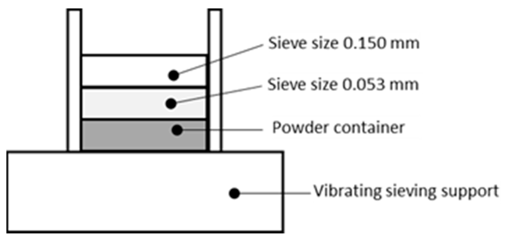
A vibrating gravity sieve column is used for this step, which is schematically represented in Figure 3. The setup consists of two sieves and a container for the collection of finer powder. At the end of each cycle, the powder is poured out of the top of the column and the vibrating sieve is activated. The vibration is maintained for at least 20 min to ensure that the entire powder sample is processed. Once finished, the powder retained on the finest sieve is collected so that the particle size of the sample is between 0.053 mm (53 µm) and 0.150 mm (150 µm).
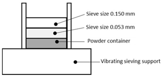
Figure 3.
Vibrating sieving column scheme.
Next step is the extraction of a powder sample (25 g) for analysis in the FESEM and for chemical analysis by ICP-OES and oxygen measurement, while the remaining powder is stored in a hermetic and standard container for the next cycle. Finally, to conclude the reuse cycle and avoid cross-contamination, all containers are cleaned with isopropyl alcohol and the sieves are placed into an ultrasonic bath for 20 min. Recycled powders were stored in containers with two silica bags for drying.
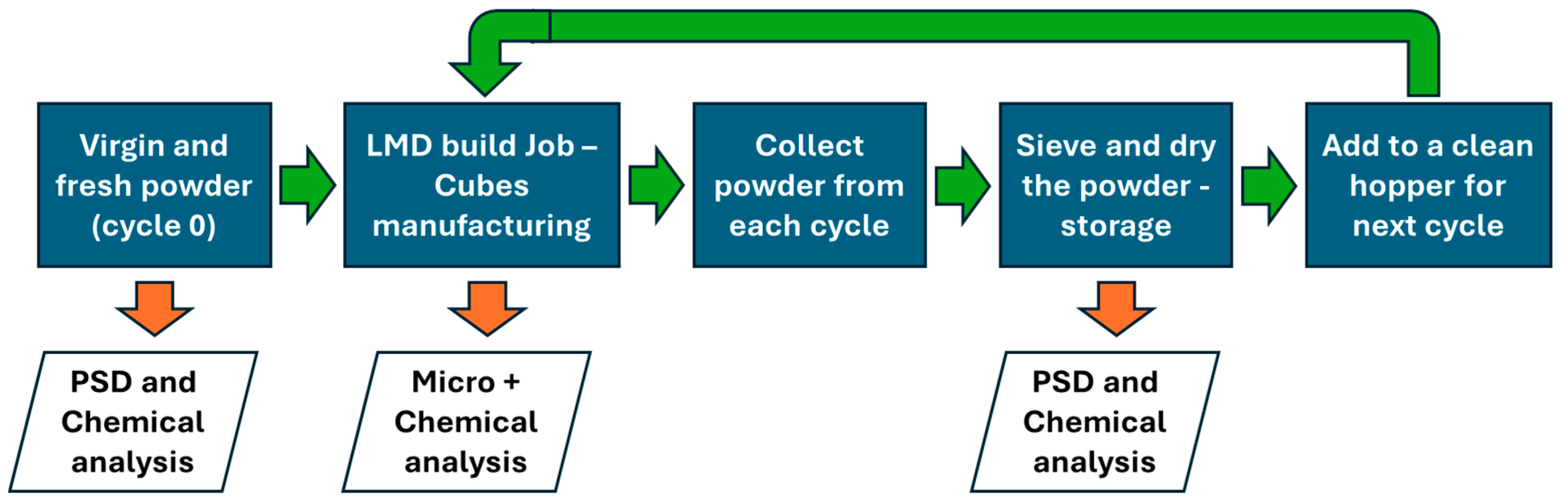
The collected and recycled powder is reused and added to a clean hopper for subsequent builds, so that this powder is not mixed with virgin powder (as is often done in the reuse methodology of PBF-LB/M powder). The reuse of all collected (and not melted) powder has been studied, with up to three cycles of use. The full workflow proposed for the powder reuse methodology including collection and stages for characterization and analysis is shown in Figure 4.
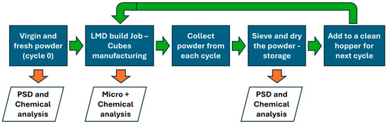
Figure 4.
Full workflow methodology proposed for the powder reuse in DED-LB (LMD) process. This methodology was used for the three cycles of use studied. Green arrows denote process steps and orange arrows denote characterization, evaluations and analysis steps.
3. Results and Their Analysis
This section describes the main findings after deep material characterization has been performed on the virgin and reused powders with the methodology previously described. It also details the manufacturing trials conducted, and geometries selected as coupons, and the results and analysis regarding chemical composition variation, microstructure, internal defects, densification and mechanical properties obtained in the materials manufactured with both virgin and reused powders, up to three times/cycles for the super duplex and for the cobalt-based Stellite® 21 type alloy.
3.1. Reused Powders—Chemical Composition and Particle Morphology Characterization
The first study conducted was the compositional element analysis in virgin and reused powder particles, following the methodologies and using the techniques stated in Section 2.1. In Table 2 and Table 3, the chemical composition measurements are compiled for Stellite® 21 and super duplex SS, respectively; it is shown that as the number of cycles increases, so does the oxygen in the powder samples collected. The rest of the chemical elements maintain stable values despite the reuse of the powder during laser processing. This effect has been observed in other studies related to the sustainability of the LMD process, for example using AISI 316L reused powder alloys [2,3].
Table 2.
Chemical composition measured (wt.%) in Stellite® 21 powder in virgin state and after three reuses.
Table 3.
Chemical composition measured (wt.%) in Super Duplex powder in virgin state and after three reuses.
On the other hand, the super duplex stainless steel powder particles are more reactive than the cobalt-based alloy studied, according to the oxygen content measured in the reused powder samples.
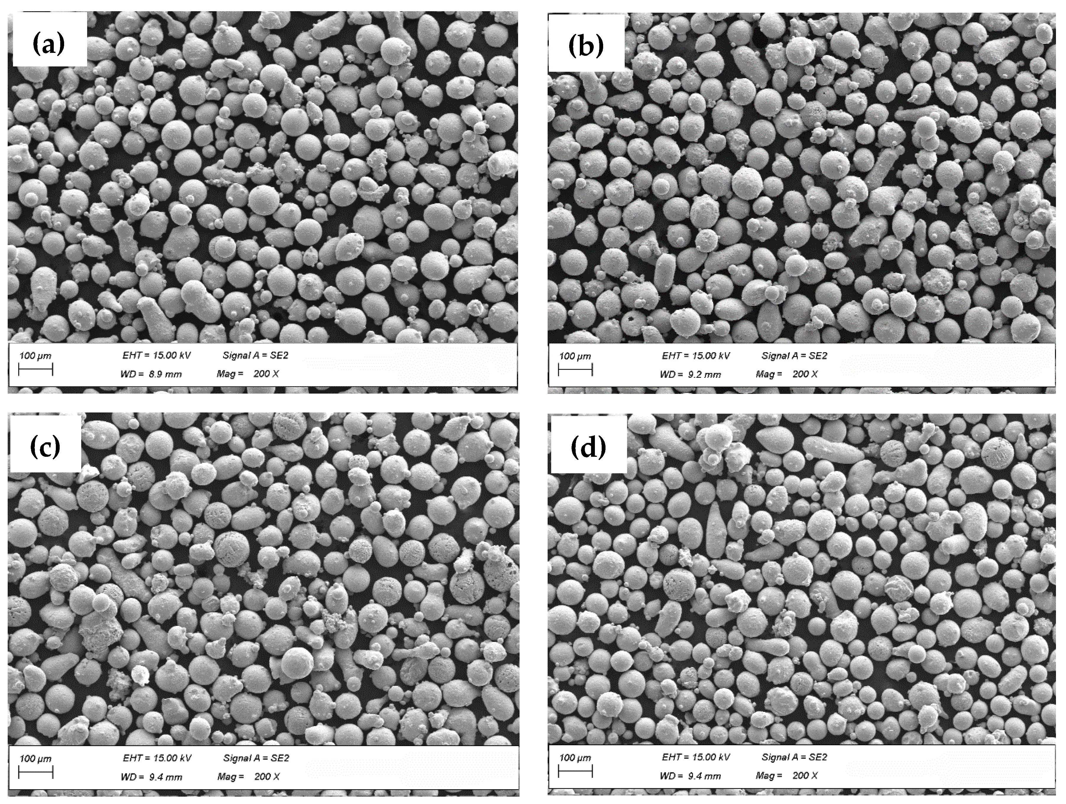
As a feedstock material quality check procedure, the powder particle virgin batch and reused samples were characterized and analysed using LOM and FESEM images. Figure 5 shows the FESEM images of super duplex SS virgin powder particles, with one use cycle, with two use cycles and with three use cycles.

Figure 5.
Micrographs of powder particles by FESEM (200× and SE mode) of super duplex stainless steel 2507: (a) virgin powder, (b) once-used powder, (c) twice-used powder and (d) thrice-used powder.
In the case of the Stellite® 21 powder, particles were observed and analysed through images and semi-quantitative chemical compositions. Figure 6 shows the FESEM images of the powder particles, with 0 (virgin), 1, 2 and 3 use cycles respectively.
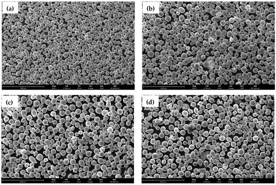
Figure 6.
Micrographs of powder particles by FESEM (200× and SE mode) of Cobalt based Stellite® 21 type alloy: (a) virgin powder, (b) once-used powder, (c) twice-used powder and (d) thrice-used powder.
As for the external appearance of the powder particles, when observed in the FESEM, no significant differences were observed; however, differences in the coloration of these particles were observed after the visual inspection, becoming darker in the samples with more than one use, which suggests a burning effect that could lead to surface oxidation of the same.
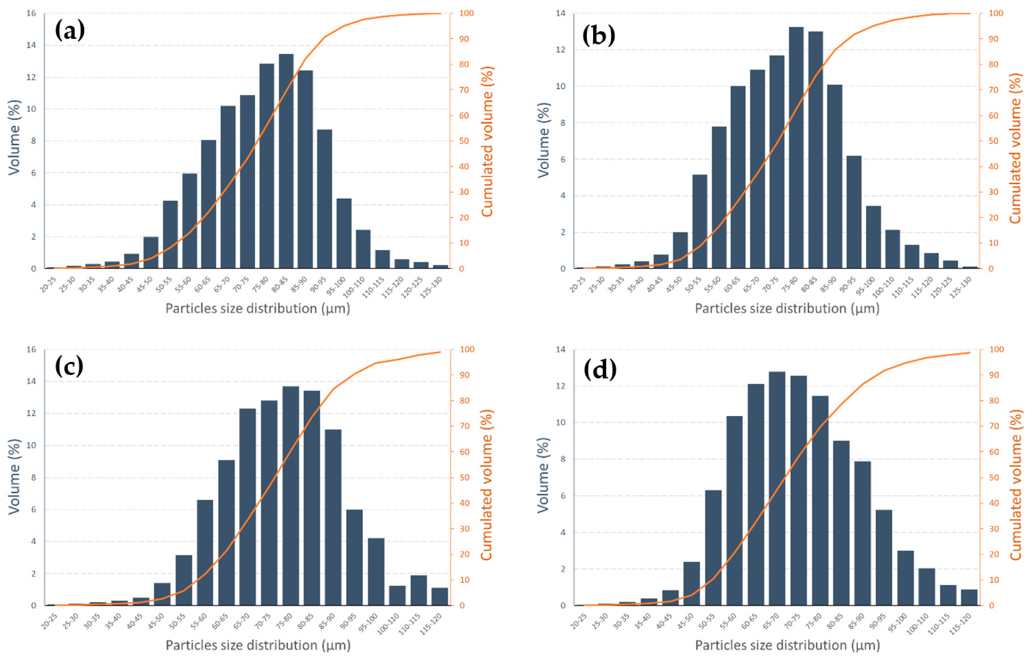
In terms of particle size distribution and morphology, there is a variation in the particle size distribution, with the virgin powder having a greater amount of large particles, measured as equivalent diameter; its particle size frequency distribution is not completely normal or Gaussian, with a tendency to skew to the right. This result may be due to the fact that in the direct laser deposition process, the smaller particles tend not to be part of the molten bath and, after successive uses of the powder, the proportion of small particles in the powder collected after the process increases compared to the larger ones, shifting the bias to the left. This can be seen for super duplex stainless steel particles in Figure 7 and for Stellite® 21 type alloy in Figure 8. The characteristic particle size parameters such as D10, D50 and D90 have also been calculated for both powders and the metrics derived from the particle’s morphology study are summarized in Table 4 and Table 5, respectively.
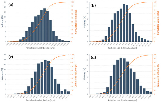
Figure 7.
Particle size distribution of SS super duplex powder sample analysed with SEM images. (a) Virgin powder, (b) once-used powder, (c) twice-used powder and (d) thrice-used powder.
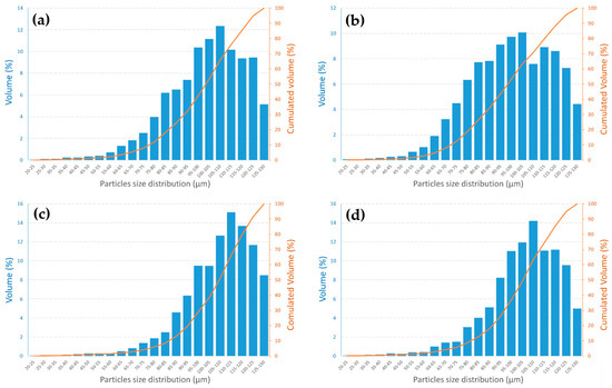
Figure 8.
Particle size distribution of Stellite® 21 type alloy powder sample analysed with SEM images. (a) Virgin powder, (b) once-used powder, (c) twice-used powder and (d) thrice-used powder.
Table 4.
Particle size distribution (PSD) in µm for materials studied.
Table 5.
Particle morphology study in powder samples studied.
Concerning the morphological analysis of the powder particles, it was observed that after the collection and sieving process of the particles, the circularity improves (one reuse powder), but as they are reused again (2nd and 3rd cycles), their circularity decreases. It has also been observed that the SDSS powder particles are smaller in diameter and more circular than the Stellite® 21 particles, which leads to the inference that they will have better flowability than the latter.
3.2. Manufacturing Trials—Geometry Selected and Process Efficiency
The depositions were applied on a rectangular substrate of grade C45 with dimensions of 100 × 200 × 30 mm3. Square multi-layer depositions of 15 mm width and 20 mm for Stellite® 21 and SDSS, respectively, were performed on the substrate, aiming to obtain 10 mm height cubes (see Figure 9), keeping the same deposition process parameters for each reuse cycle of the powder (nothing was changed in the successive rounds of cube manufacturing). Bidirectional deposition strategy was used at every layer in alternate perpendicular directions. The most relevant LMD process parameters employed for cuboids manufacturing, such as the laser power (P), linear deposition speed (S), powder flow rate (F), stepover distance (d) and layer thickness (h) are displayed in Table 6. These process parameters for cube geometries were developed from previously published research work by the authors [24] for super duplex stainless steel, and from the experience of DED-LB process technicians and the literature [11,12] for Stellite 21® type alloy. For the studies of chemical composition and microstructure analysis in the bulk material (in as-built condition), the cubes were cut from the substrate, removing the first deposited layers, to minimize the influence of the substrate material dilution with the additive material. The dilution effect has not been studied in this work.
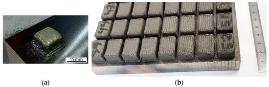
Figure 9.
Manufactured LMD Cubes: (a) Example of 15 × 15 × 10 mm3 Stellite® 21 cube manufactured with virgin powder, and (b) 20 × 20 × 10 mm3 SAF 2507 cubes manufactured with one use (one cycle) powder.
Table 6.
DED-LB process parameters for cubes manufacturing trials.
Prior to the laser metal deposition process, the build plate substrates were ground and cleaned with acetone. In addition, the substrates were weighed before and after production of each manufacturing batch to calculate the amount of material deposited in each case. The powder catchment efficiency was calculated for each sample to evaluate process effectiveness. It was obtained by dividing the amount of deposited powder by the amount of supplied powder during laser-on in the deposition trajectory path. The above steps were repeated four times to obtain the deposited samples of Stellite® 21 type alloy and SDSS obtained by LMD after reusing zero to three times. The efficiency of the catchment process did not exhibit a clear correlation with the number of powder reuse cycles (Table 7), but seems to be linked to the circularity of the particles and maybe the flowability index of them. Despite this, the process has not in fact been optimized for powder catchment efficiency. This was primarily due to the process parameters not being fine-tuned for maximum efficiency. Additionally, the cube construction process lacked a control mechanism for a constant layer height, further impacting the stand-off distance and overall efficiency of the deposition process.
Table 7.
Powder catchment efficiency of powders.
3.3. Manufacturing Trials—Bulk Material Densification, Defects and Chemical Composition
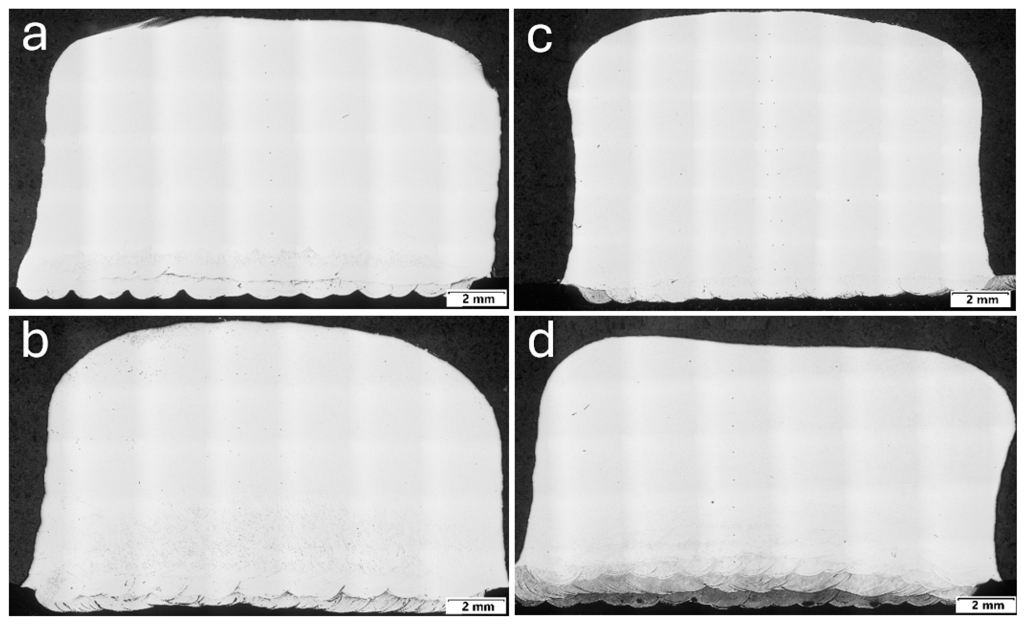
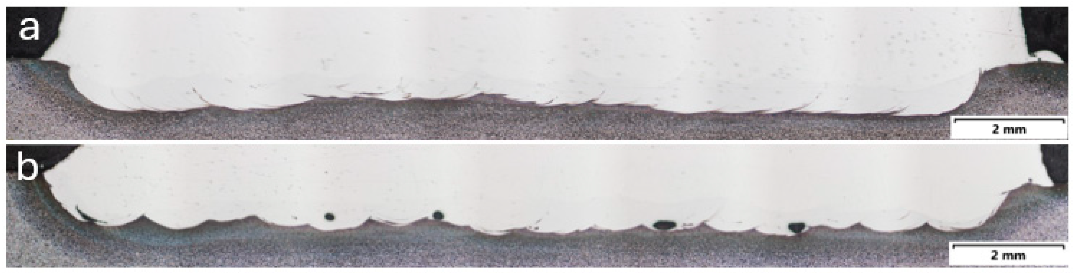
After powder reuses, the Stellite® 21 samples did not show significant internal defects. Actually, no major defects were seen throughout the analysed cross-sections of samples in the early recycling cycles (see Figure 10). However, in the third reuse, porosity appeared in the inter-diffusion zone (see Figure 11). Besides the change in geometrical shape, this could happen due to the increase of the temperature in the part during the process, but more statistics are needed to test this hypothesis. It is worth noting that the superficial colour of the deposition darkens when recycled powder is used, as reported by Terrassa et al. with reused austenitic stainless-steel powders [2].
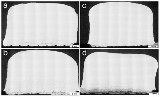
Figure 10.
Macrographs of cube cross-sections, manufactured with Stellite® 21 (a) virgin powder, (b) once-used powder, (c) twice-used powder and (d) thrice-used powder.

Figure 11.
Dilution area in manufactured cubes with Stellite® 21 (a) using once-used powder, and (b) with powder reused three times.
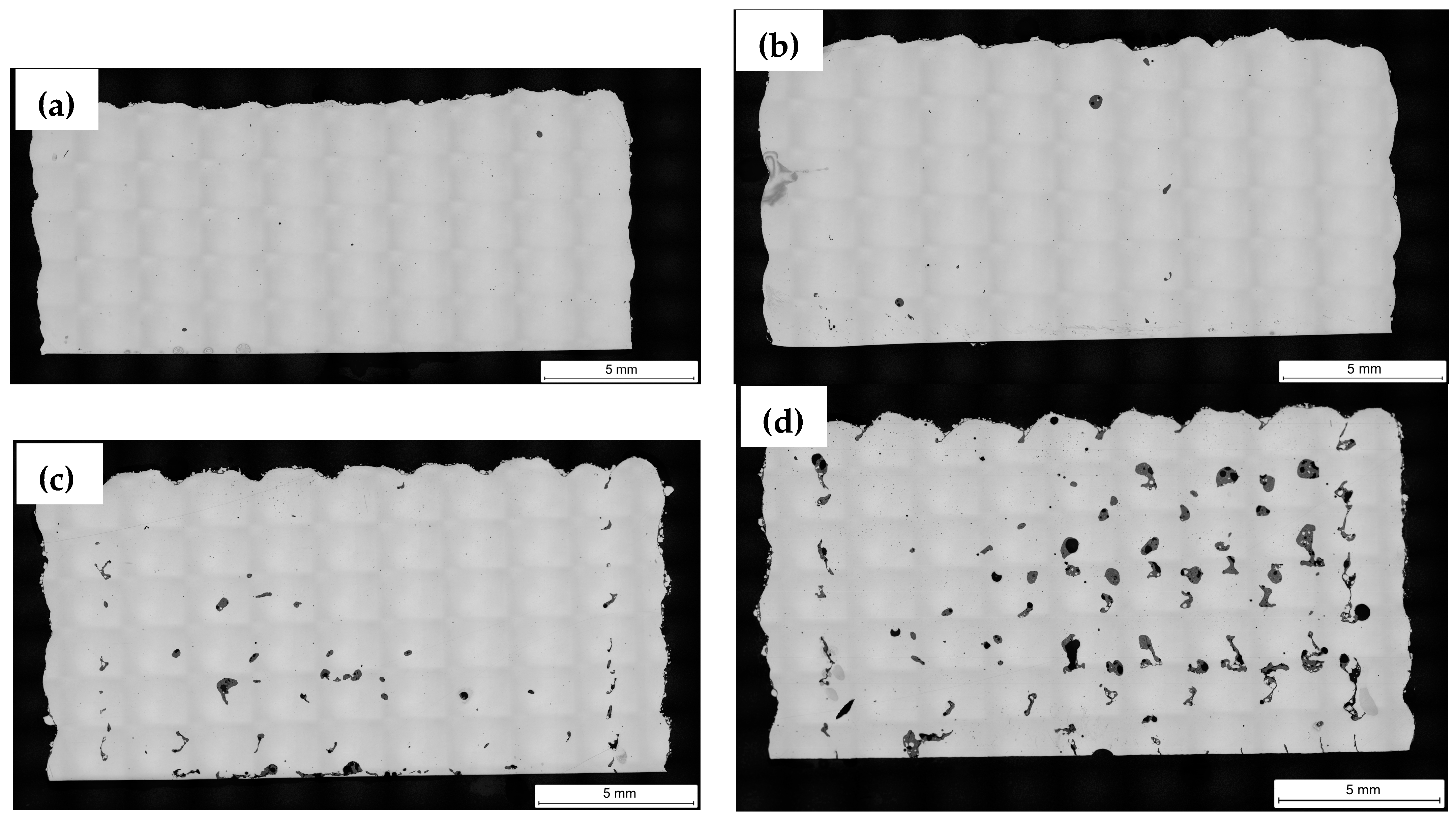
After manufacturing and cutting the bulk cubes obtained by the DED-LB (LMD) process with the super duplex stainless steel composition grade, and to evaluate their cross-section, a metallographic preparation of the samples was carried out. It is observed that the surface appearance of the cubes follows the same trend, with the cubes made from virgin powder having the best appearance. Figure 12 shows the cross section of the fabricated cubes, where the level of defects is clearly observed and more evident in the samples with two and three cycles of powder reuse.

Figure 12.
Macrographs of cubes cross-sections, manufactured with SAF 2507 super duplex steel with (a) virgin powder, (b) once-used powder, (c) twice-used powder and (d) thrice-used powder.
The internal porosity of the DED samples was measured using the LOM image analysis. Table 8 shows the measured values. In general, higher densification was obtained with virgin powders, but in the case of SDSS powder this decreased after two cycles of reuse.
Table 8.
Densification values in bulk cubes manufactured with SAF 2507 powder.
The chemical composition of the bulk cubes obtained was analysed in the same way as the powder samples collected after each manufacturing cycle. The aim was to analyse how the main elements present vary, but particularly oxygen content. Table 9 and Table 10 compile the results of the measurements obtained.
Table 9.
Chemical composition measured (wt.%) in manufactured Stellite®21 LMD cubes.
Table 10.
Chemical composition measured (wt.%) in manufactured Super Duplex LMD cubes.
As observed, there is no appreciable volatilization of chemical elements after laser metal deposition of the materials, perhaps because none of them are light elements. What is observed is the influence of the use of powder with high surface oxidation in the particles, i.e., in the SDSS samples there is a higher oxygen content in the bulk material (as-built condition), which in the case of this super duplex grade composition can have a significant impact on the formation of oxides and on the balance of austenite/ferrite phases that form the dual-phase microstructure.
3.4. As-Built Material—Microstructure Analysis
The microstructure of deposited samples is composed of dendrites (see Figure 13 and Figure 14). As the number of cycles of powder reuse increases, the deposited layers still showed good metallurgical bonding and adequate adhesion between layers. The dendrite growth direction is not continuous because of the building strategy, which alternates perpendicularly between odd and even layers. This strategy alters the thermal dissipation of each layer that is deposited, thereby inhibiting the continuous growth of columnar crystals. This behaviour was observed in both materials.

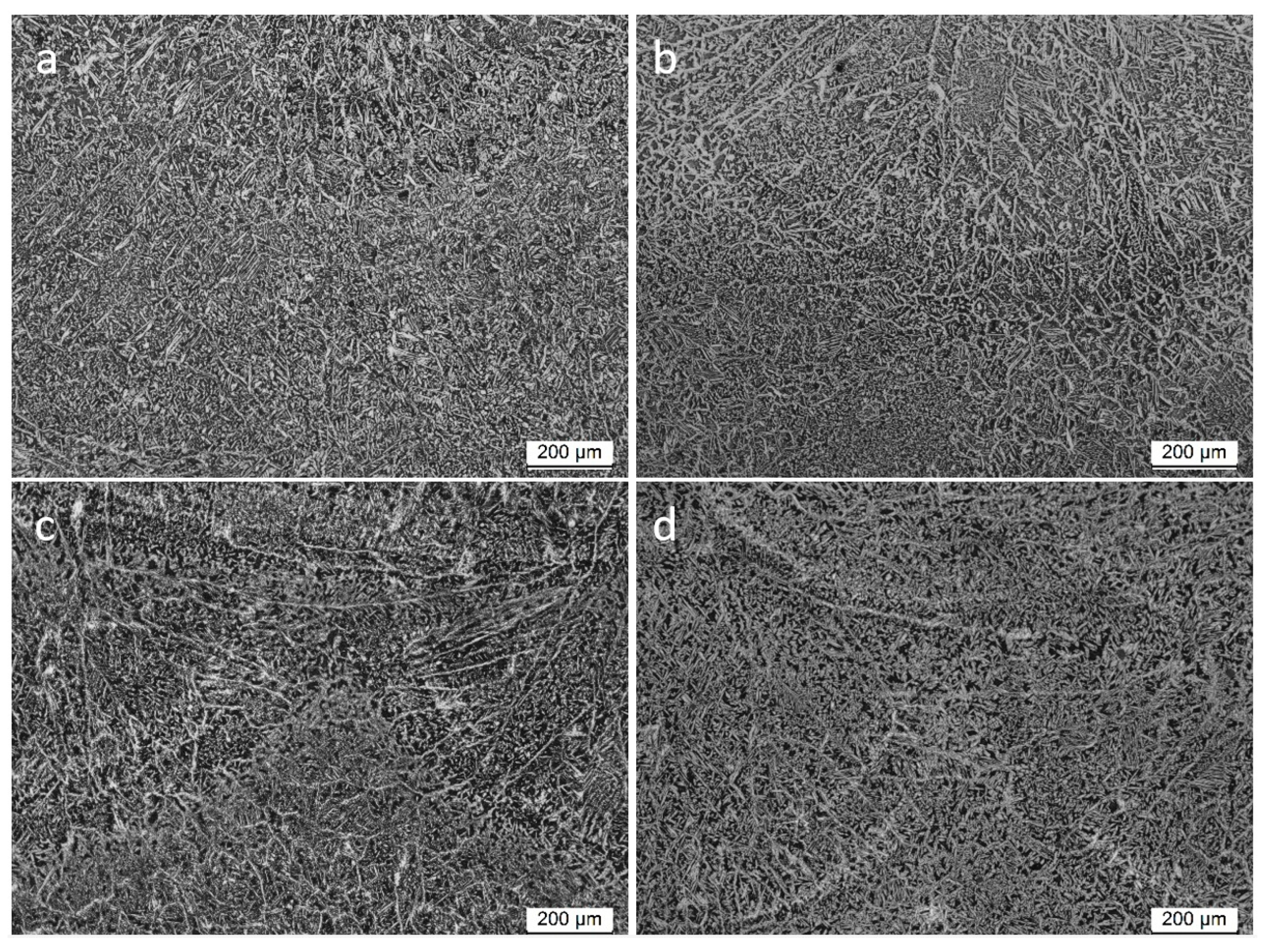
Figure 13.
Detail of dendritic structure in Stellite® 21 samples manufactured with: (a) Virgin powder (zero cycles), (b) one-reuse powder (one cycle), (c) two-reuses powder (two cycles), and (d) three-reuses powder (three cycles).
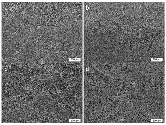
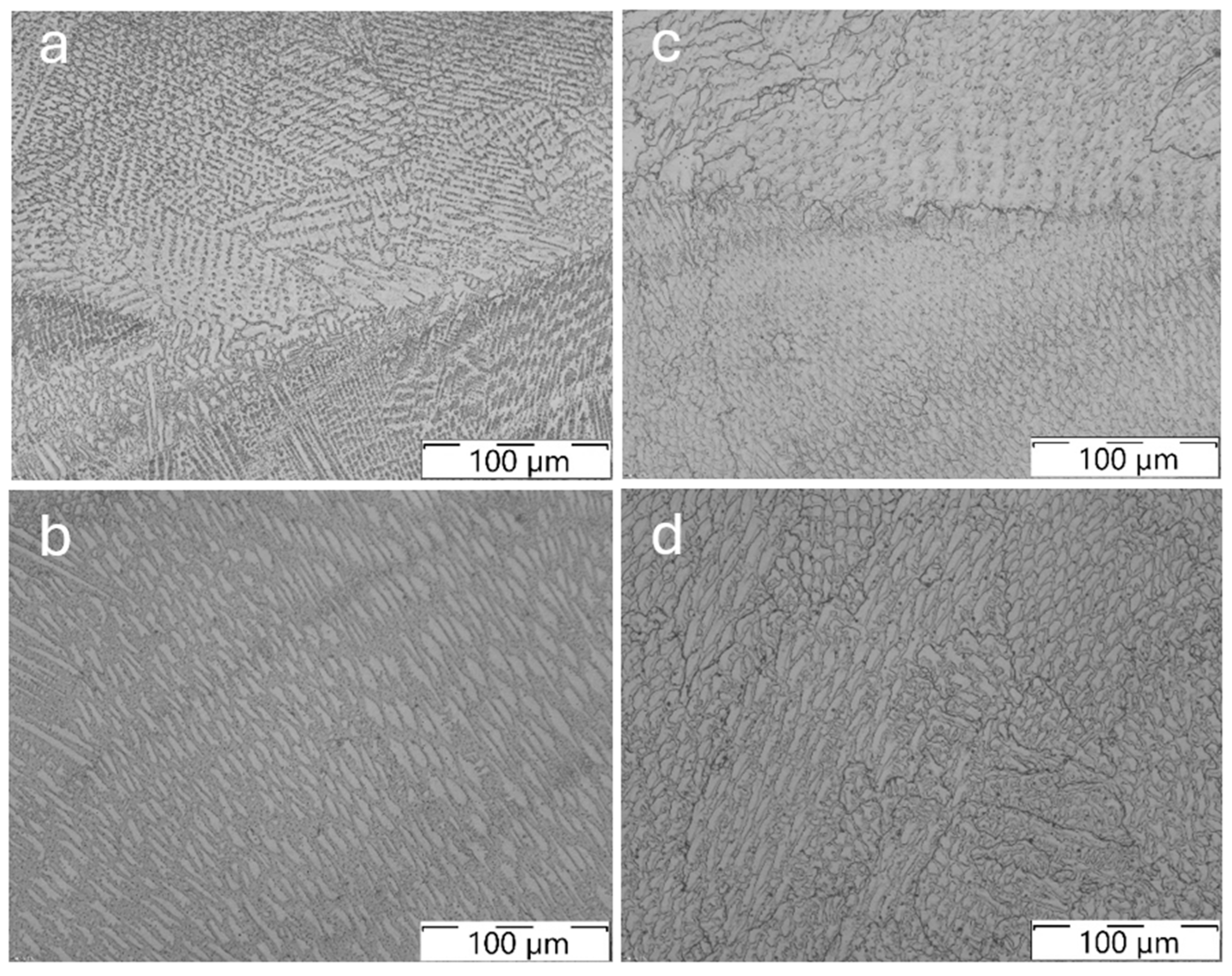
Figure 14.
Detail of austenite-ferrite dendritic structure (LOM micrograph, 100×, etched) in SAF 2507 samples manufactured with: (a) Virgin powder (zero cycles), (b) one-reuse powder (one cycle), (c) two-reuses powder (two cycles), and (d) three-reuses powder (three cycles).
In the etched condition for the SDSS sample (chemical etching by immersion in Beraha’s reagent) the dendritic microstructure is a bit coarser than the dendritic microstructure observed in the cobalt-based material. In Figure 14, the optical micrographs are compiled for SAF 2504 cubes. The microstructure of as-built material is composed of austenite-ferrite in this case.
The SDSS alloy seems to be more sensitive to the reuse of the powder than the cobalt-based alloy. At higher magnification, the unbalance of the austenite and ferrite phases is visible (see quantification values compiled in Table 11) and internal defects appear after solidification, such as pores and lack of fusion; also, oxides inclusions that usually surround these defects are more evident in the SAF 2507 samples manufactured with two- and three-reuses powder (cycles two and three), see the oxides inclusion identification and EDS maps in Figure 15 and Figure 16, respectively.
Table 11.
Phase quantification in the microstructure of bulk cubes manufactured with SAF 2507 powder.

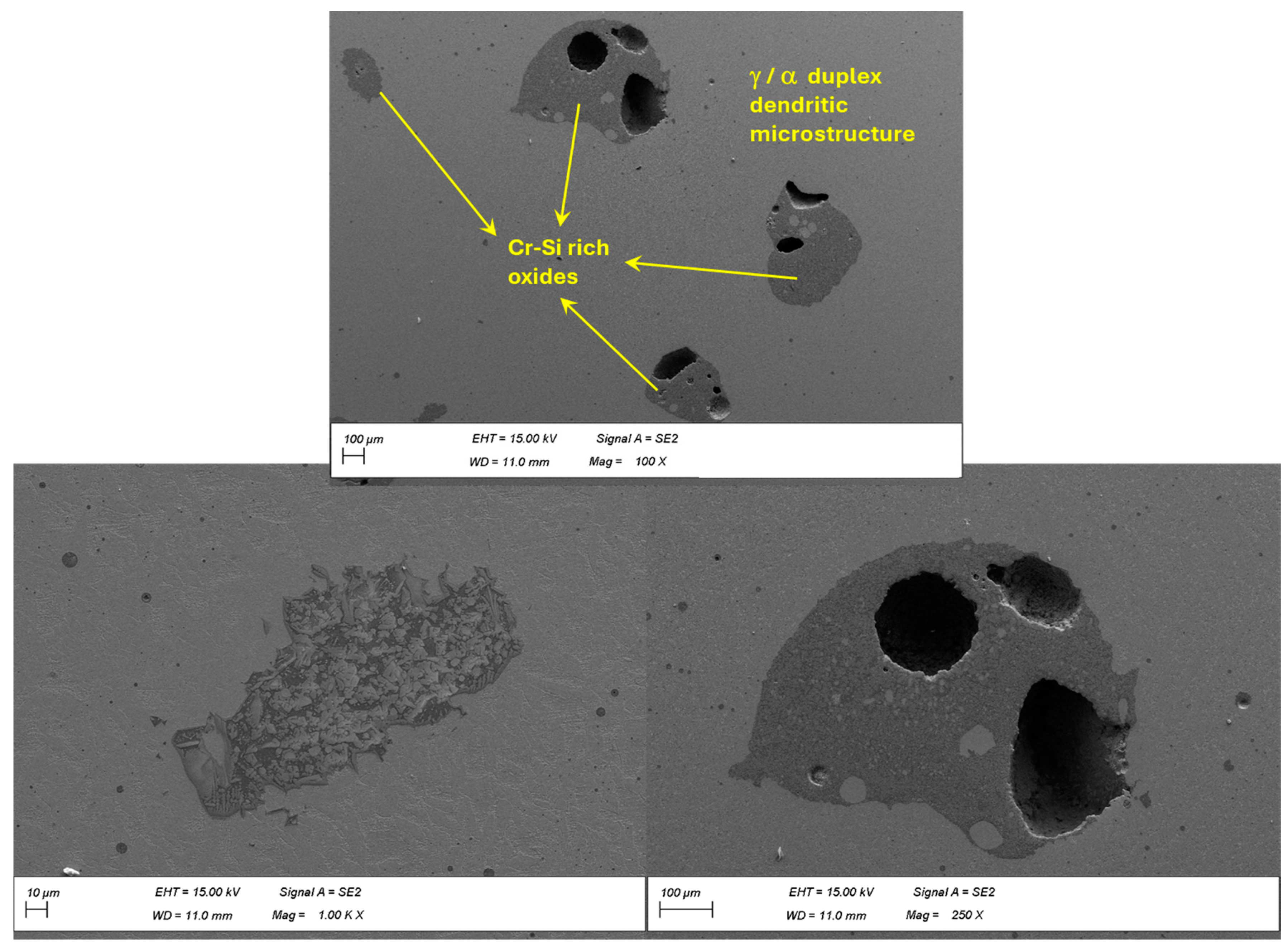
Figure 15.
Detail of Cr-Si rich oxides present in a SAF 2507 cube manufactured with thrice-used powder (FESEM micrographs at 250× and 1000×, BSE mode, sample polished).

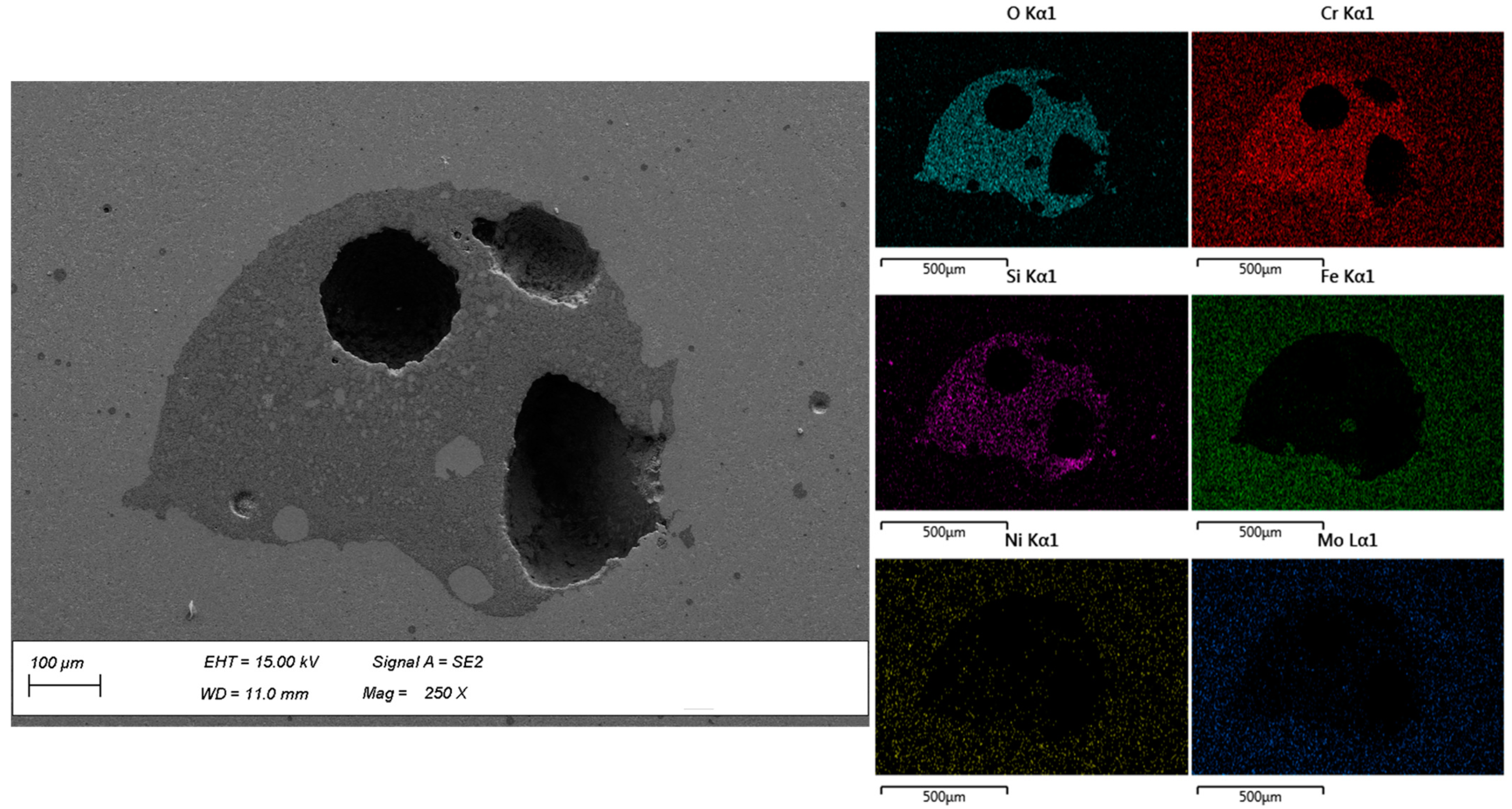
Figure 16.
FESEM micrograph (BSE mode, 250×) and EDS maps of Cr-Si rich oxide present in a SAF 2507 cube manufactured with thrice-used powder (three cycles).
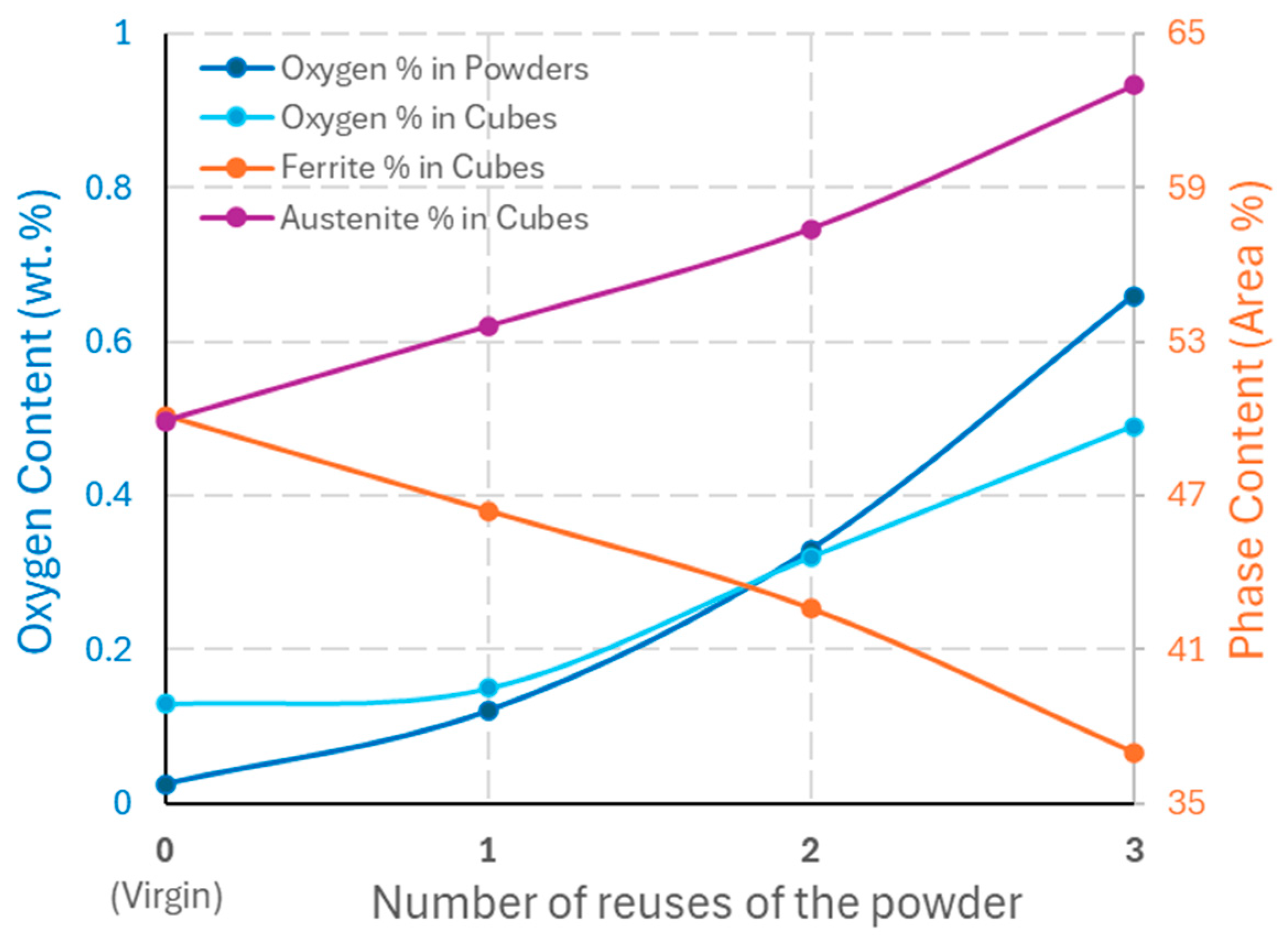
The relation between oxygen content and the stabilization of austenite and Cr-Si rich oxides formation in the super duplex stainless steel is evident. As can be observed in Figure 17, the higher the oxygen content in the bulk material (present mainly in the form of oxides around the pores and fusion faults), the greater the stabilization of the austenite phase, so that after solidification of the material a lower proportion of the ferrite phase is obtained. This is because oxygen is itself a gamma-magnetic element, and this promotes the stabilization of the austenite phase in SS. The ferrite ratio drops from 0.50 using virgin powder to 0.37 using reused powder in three processing cycles by LMD.
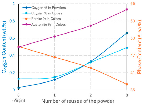
Figure 17.
Evolution of oxygen content in powders and cubes and main phases present in the microstructure of SAF 2507 super duplex stainless steel obtained by LMD (DED-LB) process.
3.5. As-Built Material—Mechanical Properties/Hardness
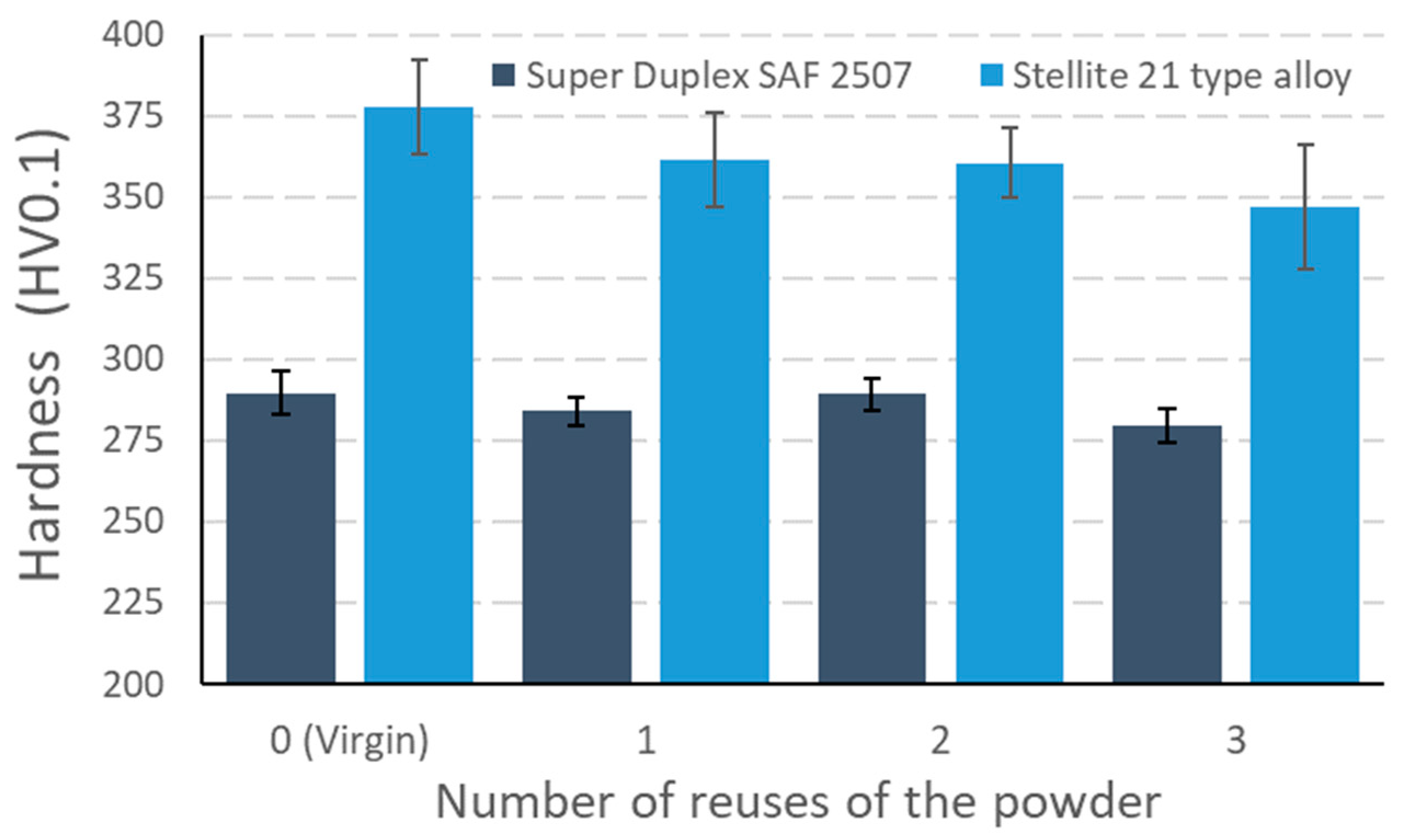
Vickers micro-hardness measurements of every Stellite® 21 sample was obtained from the surface of the cube to the interface between the deposited and substrate materials every 1 mm with a load of 0.5 kg. The resulting average micro-hardness value for each sample is represented in Figure 18. The hardness of the samples decreases as the powder is reused. This can be caused by the reduction of carbon and manganese and increment of oxygen content in the cubes manufactured with reused powder, considering that the C content of a Stellite® 21 alloy determines the volume fraction of carbides precipitated in the alloy and hence its hardness, as reported previously by Liu et al. [25].
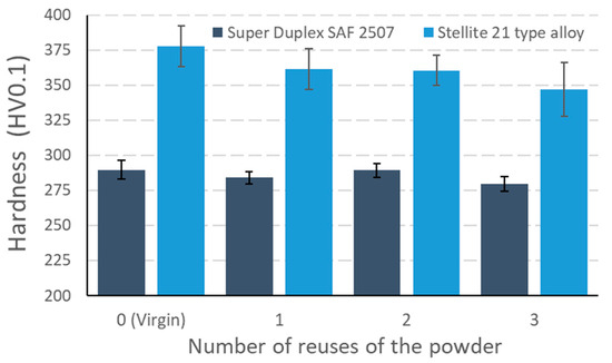
Figure 18.
Average microhardness measured in cross-section of cubes manufactured by LMD with virgin and reused powder.
Hardness measurements were also performed in super duplex cubes cross-sections, making a sweep with indentations from the surface of the cube; the first indentation was made at 250 µm from the surface and then the following ones separated 500 µm between them, reaching the first layer. In a similar way, the hardness of SAF 2507 LMD samples decreases as the powder is reused (see the graph of Figure 18), because the amount of oxygen increases and more oxides and austenite are formed, lowering the strength due to reduced ferrite content in comparison with samples produced with virgin powder.
4. Conclusions
The main conclusions based on the results obtained and their analysis in this research work are as follows:
- A methodology has been proposed for the reuse of unmelted metallic powder after the DED-LB (LMD) manufacturing process. Two different alloys, one cobalt-based and one iron-based, have been evaluated and processed at two LMD robotic stations in different locations for the evaluation of the reuse of powders.
- In the present study, cobalt-based alloys such as the Stellite® 21 type are less reactive and less sensitive to powder reuse in the DED-LB (LMD) process than super duplex stainless steel type SAF 2507 (similar to UNS S32750/DIN 1.4410). This is because cobalt-based alloys are a less reactive material and not prone to oxides formation and austenitic phase stabilisation in their microstructure.
- In general, higher densification was obtained in as-built samples manufactured with virgin powders, but in the case of SDSS powder the densification decreases after two cycles of reuse. No loss of densification was observed in the case of Stellite® 21 type alloy, in fact the densification after three reuses in this powder did not drop below 99.74%.
- The ferrite ratio (proportion of ferrite in the duplex microstructure) drops from 0.50 using virgin powder to 0.37 after three reuse cycles in the case of super duplex stainless steel. This can have a strong influence on the performance of components manufactured by DED-LB and subjected to corrosion and loading.
- The average micro-hardness of the deposited samples of Stellite® 21 and SAF 2507 super duplex stainless steel decreases as the powder reuse increases due to the fact that the oxygen content increases, and the reduction of carbon and manganese in the cobalt-based alloy and the formation of oxides and austenite for the SDSS alloy.
- Powder particles of super duplex stainless steel alloy can be reused only one time without an increase of internal porosity and oxides formation within deposited layers in the additive process, while powder particles of the Stellite® 21 type alloy can be reused up to three times without an increase in internal porosity or lack of fusion in the deposited material.
Author Contributions
Conceptualization, J.C.P.; Data curation, U.I. and D.G.; Formal analysis, J.C.P., A.S. and D.G.; Funding acquisition, J.C.P., C.S. and A.L.; Investigation, U.I., A.S. and J.E.R.; Methodology, A.S.; Resources, J.E.R.; Supervision, A.L.; Writing—original draft, U.I., A.S. and D.G.; Writing—review & editing, J.C.P., C.S. and A.L. All authors have read and agreed to the published version of the manuscript.
Funding
This research work was supported by the Basque Government (Eusko Jaurlaritza, Department of Economic Development and Infrastructure, Programme ELKARTEK) through EDISON project (grant KK-2022/00070) and through ECOFAST project (grant KK-2024/00018).
Data Availability Statement
The data presented in this study are available on request from the corresponding author due to technical or time limitations.
Conflicts of Interest
The authors declare no conflicts of interest.
References
- Gutjahr, J.; Pereira, M.; de Sousa, J.M.S.; Ferreira, H.S.; Júnior, A.T. Powder degradation as a consequence of laser interaction: A study of SS 316L powder reuse on the laser directed energy deposition process. J. Laser Appl. 2024, 36, 12022. [Google Scholar] [CrossRef]
- Terrassa, K.L.; Haley, J.C.; MacDonald, B.E.; Schoenung, J.M. Reuse of powder feedstock for directed energy deposition. Powder Technol. 2018, 338, 819–829. [Google Scholar] [CrossRef]
- Li, S.; Chen, B.; Tan, C.; Song, X. Study on Recyclability of 316L Stainless Steel Powder by Using Laser Directed Energy Deposition. J. Mater. Eng. Perform. 2022, 31, 400–409. [Google Scholar] [CrossRef]
- Verdi, D.; Yang, S.; Soh, N.; Tay, G.; Patran, A. The Role of Powder Feedstock in Directed Energy Deposition Sustainability; ASTM International: West Conshohocken, PA, USA, 2022. [Google Scholar] [CrossRef]
- Joju, J.; Verdi, D.; Han, W.S.; Hang, L.Y.; Soh, N.; Hampo, C.C.; Liu, N.; Yang, S.S. Sustainability assessment of feedstock powder reuse for Directed Laser Deposition. J. Clean. Prod. 2023, 388, 136005. [Google Scholar] [CrossRef]
- Warner, J.H.; Ringer, S.P.; Proust, G. Strategies for metallic powder reuse in powder bed fusion: A review. J. Manuf. Process. 2024, 110, 263–290. [Google Scholar] [CrossRef]
- Li, J.; Liu, W.; Shen, J.; Zhang, X.; Li, S.; Wang, Z. Research progress of the metal powder reuse for powder bed fusion additive manufacturing technology. Powder Technol. 2024, 441, 119815. [Google Scholar] [CrossRef]
- Santecchia, E.; Spigarelli, S.; Cabibbo, M. Material Reuse in Laser Powder Bed Fusion: Side Effects of the Laser—Metal Powder Interaction. Metals 2020, 10, 341. [Google Scholar] [CrossRef]
- Lanzutti, A.; Marin, E. The Challenges and Advances in Recycling/Re-Using Powder for Metal 3D Printing: A Comprehensive Review. Metals 2024, 14, 886. [Google Scholar] [CrossRef]
- Yao, J.; Zhang, Q.; Liu, R.; Wu, G. (Eds.) Laser Cladding of Stellite Alloys BT—Laser Applications in Surface Modification; Springer: Singapore, 2022; pp. 11–57. [Google Scholar] [CrossRef]
- Díaz, E.; Tobar, M.J.; Yáñez, A.; García, J.; Taibo, J. Laser Powder Welding with a Co-based alloy for repairing steam circuit components in thermal power stations. Phys. Procedia 2010, 5, 349–358. [Google Scholar] [CrossRef]
- Díaz, E.; Amado, J.M.; Montero, J.; Tobar, M.J.; Yáñez, A. Comparative Study of Co-based Alloys in Repairing Low Cr-Mo steel Components by Laser Cladding. Phys. Procedia. 2012, 39, 368–375. [Google Scholar] [CrossRef]
- Kendall, O.; Abrahams, R.; Paradowska, A.; Reid, M.; Qiu, C.; Mutton, P.; Schläfer, T.; Yan, W. Influence of multi-layer laser cladding depositions and rail curvature on residual stress in light rail components. Eng. Fail. Anal. 2023, 150, 107330. [Google Scholar] [CrossRef]
- Foster, J.; Cullen, C.; Fitzpatrick, S.; Payne, G.; Hall, L.; Marashi, J. Remanufacture of hot forging tools and dies using laser metal deposition with powder and a hard-facing alloy Stellite 21®. J. Remanuf. 2019, 9, 189–203. [Google Scholar] [CrossRef]
- Tavares, S.S.M.; Pardal, J.M.; Lima, L.D.; Bastos, I.N.; Nascimento, A.M.; de Souza, J.A. Characterization of microstructure, chemical composition, corrosion resistance and toughness of a multipass weld joint of superduplex stainless steel UNS S32750. Mater. Charact. 2007, 58, 610–616. [Google Scholar] [CrossRef]
- Tan, H.; Jiang, Y.; Deng, B.; Sun, T.; Xu, J.; Li, J. Effect of annealing temperature on the pitting corrosion resistance of super duplex stainless steel UNS S32750. Mater. Charact. 2009, 60, 1049–1054. [Google Scholar] [CrossRef]
- Jiang, D.; Gao, X.; Zhu, Y.; Hutchinson, C.; Huang, A. In-situ duplex structure formation and high tensile strength of super duplex stainless steel produced by directed laser deposition. Mater. Sci. Eng. A 2022, 833, 142557. [Google Scholar] [CrossRef]
- Iams, A.D.; Keist, J.S.; Palmer, T.A. Formation of Austenite in Additively Manufactured and Post-Processed Duplex Stainless Steel Alloys. Metall. Mater. Trans. A 2020, 51, 982–999. [Google Scholar] [CrossRef]
- Iams, A.D.; Keist, J.S.; Giannuzzi, L.A.; Palmer, T.A. The Evolution of Oxygen-Based Inclusions in an Additively Manufactured Super-Duplex Stainless Steel. Metall. Mater. Trans. A 2021, 52, 3401–3412. [Google Scholar] [CrossRef]
- Brázda, M.; Salvetr, P.; Rzepa, S.; Melzer, D.; Vavrik, J. Effect of heat treatment on mechanical properties of duplex steel SAF 2507 manufactured by DED. IOP Conf. Ser. Mater. Sci. Eng. 2021, 1178, 12008. [Google Scholar] [CrossRef]
- ASTM E562-19e1; Standard Test Method for Determining Volume Fraction by Systematic Manual Point Count. ASTM International: West Conshohocken, PA, USA, 2020; pp. 1–7. [CrossRef]
- ASTM E1019-18; Standard Test Methods for Determination of Carbon, Sulfur, Nitrogen, and Oxygen in Steel, Iron, Nickel, and Cobalt Alloys by Various Combustion and Inert Gas Fusion Techniques. ASTM International: West Conshohocken, PA, USA, 2018. [CrossRef]
- UNE-EN 10361:2016; Aceros Aleados. Determinación del Contenido de Níquel. Método por Espectrometría de Emisión Óptica con Fuente de Plasma Inducido. ASTM International: West Conshohocken, PA, USA, 2019.
- Pereira, J.C.; Aguilar, D.; Tellería, I.; Gómez, R.; Sebastian, M.S. Semi-Continuous Functionally Graded Material Austenitic to Super Duplex Stainless Steel Obtained by Laser-Based Directed Energy Deposition. J. Manuf. Mater. Process. 2023, 7, 150. [Google Scholar] [CrossRef]
- Liu, R.; Ding, Y.; Kamal, K. Advanced Super Alloys with High Performance for Severe Operation Environment Applications. Published in International Journal of Trend in Research and Development (IJTRD), ISSN: 2394-9333, Conference Proceeding|IPMESS-19, June 2019. Available online: http://www.ijtrd.com/papers/IJTRD20589.pdf (accessed on 23 July 2024).


Disclaimer/Publisher’s Note: The statements, opinions and data contained in all publications are solely those of the individual author(s) and contributor(s) and not of MDPI and/or the editor(s). MDPI and/or the editor(s) disclaim responsibility for any injury to people or property resulting from any ideas, methods, instructions or products referred to in the content. |
© 2024 by the authors. Licensee MDPI, Basel, Switzerland. This article is an open access article distributed under the terms and conditions of the Creative Commons Attribution (CC BY) license (https://creativecommons.org/licenses/by/4.0/).