Article

Experimental Investigation and Prediction for Bending Creep of Glass Fiber-Reinforced Polymer Pultruded Tube

1
College of Civil Engineering, Nanjing Tech University, Nanjing 211816, China
2
Nanjing Jiangbei New Area Construction and Traffic Engineering Quality and Safety Supervision Station, Nanjing 210000, China
*
Author to whom correspondence should be addressed.
Buildings 2023, 13(11), 2714; https://doi.org/10.3390/buildings13112714
Submission received: 7 October 2023 / Revised: 24 October 2023 / Accepted: 26 October 2023 / Published: 27 October 2023

Abstract

:
This study experimentally investigates the bending creep behavior of a pultruded tube made of glass fiber-reinforced polymer (GFRP) and provides the corresponding fitting model as well as the life prediction equation. In the experiment process, the static bending test is performed first to determine the ultimate load-bearing capacities. Then, the creep experiments lasting 3000 h are conducted for GFRP pultruded tubes with 50%, 55%, 60%, and 65% fiber contents, subjected to four different load levels, i.e., 20%, 32.5%, 45%, 57.5%, and 70%, of the ultimate load-bearing capacity. The results indicate that the creep behavior exhibits linear viscoelasticity for load levels below 45%, while the specimens under load levels of 57.5% and 70% experienced creep failure before 1500 h. The test results indicate that for GFRP tubes, the higher the load level, the more pronounced the creep deformation, and specimens with a higher fiber content exhibit better creep resistance compared to those with lower fiber content. When the load level is less than 45%, the creep behavior appears as linear viscoelasticity. However, at a load level of 57.5%, the specimens experience shear failure, and at a load level of 70%, the specimens undergo overall bending failure. In addition, the prediction equation of creep deflection for GFRP pultruded tubes in linear viscoelasticity is developed by utilizing the Bailey–Norton model and the Findley model, and the prediction equation of creep life is acquired by fitting the experimental data with an exponential function.

1. Introduction

Fiber-reinforced polymer (FRP) composites are characterized by their high strength, low weight, outstanding impact resistance, optimized stiffness, and flexural performance, along with design flexibility, enabling them to meet the specific demands of diverse engineering and product applications [1,2]. Even though FRP is a new-generation material, there are also mature technologies for cyclic utilization, such as mechanical recycling and thermal treatment [3,4]. Additionally, FRP exhibits varying properties and advantages based on the type of fibers used. For example, carbon fiber-reinforced polymer exhibits excellent mechanical properties, outstanding fatigue performance, corrosion resistance, and creep resistance [5]. In contrast, basalt fiber-reinforced polymer (BFRP) and GFRP also possess good mechanical properties, but their long-term mechanical performance and fatigue resistance may be affected in alkaline concrete environments [6,7]. Meanwhile, FRP generally has a long service life, and thus FRP is a kind of sustainable material in engineering. Common methods for producing FRP composites encompass pultrusion, hand layup, compression molding, filament winding, and vacuum bagging, among others. Among these techniques, pultrusion distinguishes itself with several advantages, including continuous production, high automation, superior strength and uniformity, and the ability to integrate multiple materials. Consequently, FRP pultruded profiles have gained extensive applications in industries, such as aerospace, automotive, and infrastructure [8,9,10,11]. However, due to the pronounced creep phenomenon in long-term loaded FRP profiles caused by viscoelastic property in a polymer matrix [12,13], engineering practice typically employs a strategy of increasing design margins to maintain the FRP profiles in a low-stress state, thereby mitigating the effects of long-term creep. Nonetheless, this approach also reduces cost-effectiveness and somewhat constrains its widespread application in engineering. As a result, the creep behavior of long-term loaded FRP pultruded profiles have become an urgent matter to be thoroughly investigated [14,15].
Scholars have undertaken relevant research on the mechanical properties of FRP pultruded profiles. Liu Xing [16] conducted research on the long-term performance of FRP profiles in marine environments. The study revealed that marine environments have a minimal impact on fiber-dominated mechanical properties, e.g., tensile performance, but they significantly affect the mechanical properties dominated by the resin and fiber–matrix interface, e.g., bending. Lu [17,18] performed four-point bending tests on a glass fiber-reinforced polymer (GFRP), and the results showed that the load-deflection response of specimens approaches a hyperbolic curve, indicating that GFRP exhibits quasi-ductility. Liu [19] investigated the load-bearing performance of concrete beams with embedded FRP I-section profiles. The results indicated that the ultimate bearing capacity of the specimens increases with the improvement of concrete strength, steel yield strength, and steel content, whereas the initial stiffness of the specimens is essentially unaffected. Fei et al. [20] examined the mechanical properties of GFRP profiles, and they found that the bending strength increases with fiber content. Feng et al. [21] employed a combined approach of experimental testing and finite element analysis to explore the mechanism and failure modes of long columns with embedded FPR I-section profiles in square steel tube-reinforced concrete under bi-axial loading conditions. Li [22] analyzed the flexural behavior of GFRP profile concrete composite beams based on a nonlinear viscoelastic model. Zhang [23] investigated the flexural behavior of FRP-concrete composite beams and proposed predictive formulas for flexural capacity and stiffness.
Despite extensive research into the mechanical properties of FRP profile, there remains a scarcity of studies focusing on its long-term creep behavior. Li et al. [24,25] conducted an experimental investigation into the bending creep of sandwich beams composed of GFRP skins and lightweight wood cores. The findings reveal linear viscoelastic creep behavior below a 40% load level. However, at load levels of 60% and 80%, all specimens experience creep failure. Among these, specimens at 60% load exhibit two failure modes, core shear and overall bending, whereas specimens at 80% load only experience bending failure. Dutta et al. [26] explored the tensile and compressive creep behavior of GFRP sheets at different temperatures and established a fitting equation to predict creep failure time. The experiments demonstrated that the fundamental nature of classic viscoelastic and viscoplastic behaviors dominating composite materials remained consistent at elevated temperatures. The proposed equation bears a resemblance to the power-law creep equation put forth by Findley in terms of its properties. Zhang et al. [27] conducted a 3000 h test on GFRP composite sheets subjected to a three-point bending load. The exceptional flexural creep resistance of this composite material was observed, suggesting its suitability for bending load conditions. Furthermore, it is suggested that the creep data from the first 480 h can be utilized as the creep design limit for practical engineering applications. Xu [28] analyzed the impact of environmental humidity on the creep behavior of flax fiber-reinforced polymer and found that the initial creep stage is crucial in structural design, with the total strain, including instantaneous elastic strain and creep strain, increasing with rising relative humidity. The total strain, which consists of instantaneous elastic strain and creep strain, increases with the rise in relative humidity. Ana [29] conducted further research on the long-term characteristics and time-dependent behavior of BFRP and provided a numerical expression for analyzing the creep of BFRP columns. The results indicated similarities between creep test data and relaxation data. Currently, the creep performance of composite material structures in experimental research is typically analyzed using parameter-based phenomenological theoretical models. Among these models, the most commonly used one is the Findley power-law model. This model was introduced by Findley in 1944 and has been successfully applied to describe the creep response of polymer materials [30,31].
GFRP pultruded tubes, being a novel structural component, have limited engineering research, often resulting in overdesign due to the absence of specific regulatory requirements and the common adoption of oversized cross-sectional designs. This excessive surplus reduces cost-effectiveness and restricts widespread adoption. Therefore, investigating the bending creep performance of composite materials is crucial for long-term load-bearing GFRP pultruded tubes, facilitating their design and extensive application. To the best of the authors’ knowledge, the bending creep behavior of the GFRP pultruded profile, which is commonly utilized in infrastructure engineering, has not been studied yet. This study investigates the bending creep behavior of a GFRP pultruded tube with different four fiber contents, subjected to four different load levels, via a 3000 h three-point bending test. In addition, the prediction equation of creep deflection in linear viscoelasticity range is developed by utilizing the Bailey–Norton model and the Findley model, and the prediction equation of creep life is established by fitting the experimental data with an exponential function.

2. Experimental Methods

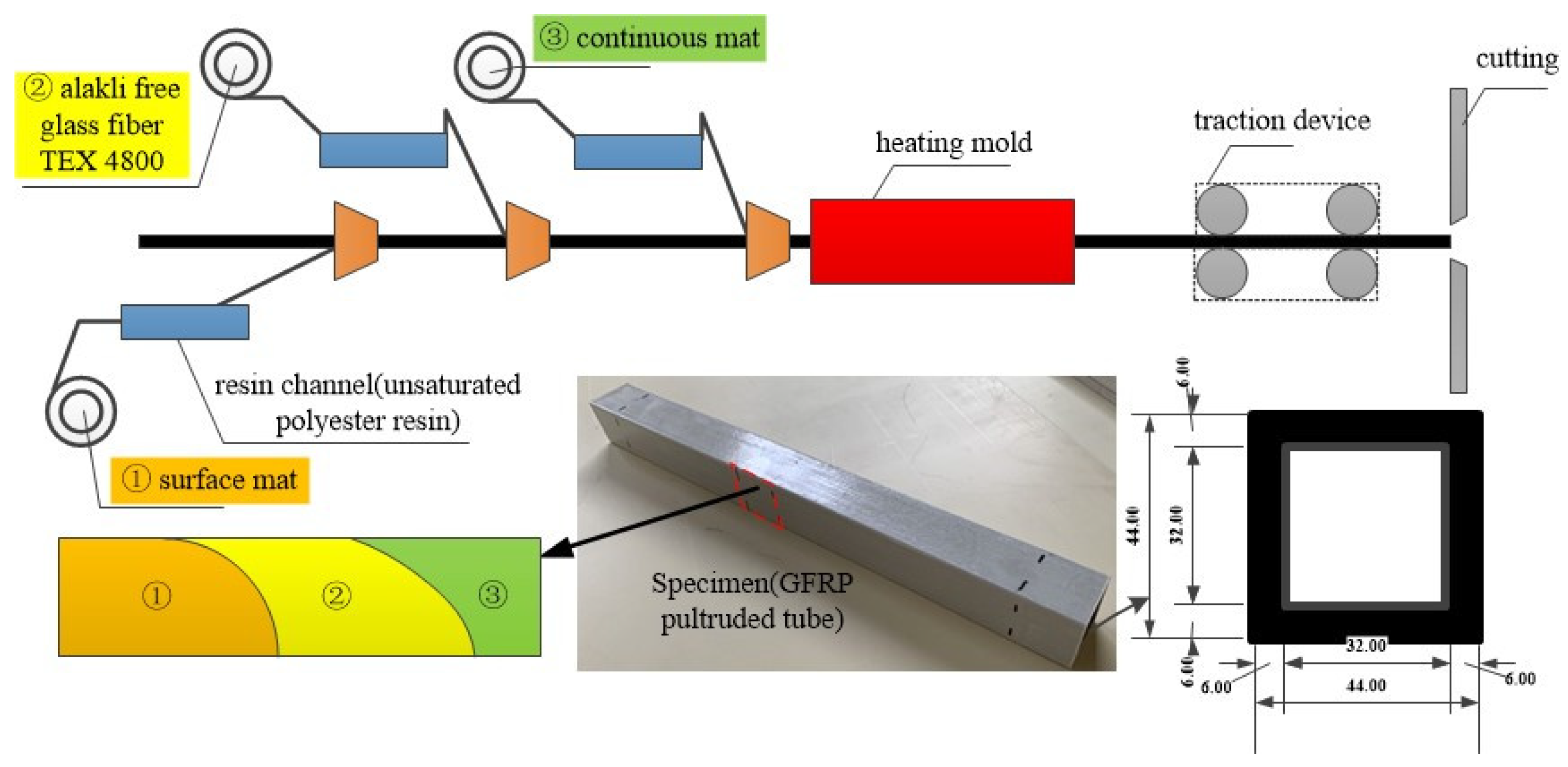
2.1. Description of Specimen

As shown in Figure 1, the test specimen is a GFRP pultrusion tube with a square cross-section and a length of 400 mm, mainly made of alkali-free glass fiber TEX4800 and unsaturated polyester resin. Alkali-free glass fiber TEX4800 in this composition demonstrates high strength, typically around 2800 MPa. It also exhibits significant stiffness, generally characterized by an elastic modulus ranging from 80 GPa. Despite these qualities, it maintains a relatively low density, typically around 2.54 g/cm3, making it a lightweight material. On the other hand, unsaturated polyester resin offers high customizability, with the ability to cure at room temperature in just 20 min, and it exhibits excellent adhesion when combined with reinforcing materials like glass fibers, providing additional strength and rigidity.
In the GFRP pultrusion tube, the outer layer is composed of a surficial fiber mat and continuous fiber mat, and the middle and inner layers incorporate TEX4800 roving and continuous fiber mat. The glass fibers are immersed in unsaturated polyester resin, ensuring thorough resin infiltration and complete fiber envelopment. Then, the impregnated glass fiber materials are subjected to a molding process, facilitated by an extrusion machine. At last, the produced GFRP tube undergoes precision cutting, shaping, and refinement processes, ensuring compliance with specified standards and quality criteria.
The GFRP pultrusion tubes with four different fiber contents, i.e., 50%, 55%, 60%, and 65%, were subjected to five load levels, including 20%, 32.5%, 45%, 57.5%, 70%, and 100% of the ultimate load-bearing capacity, are utilized in the static and creep bending tests. Four different glass fiber content levels, 50%, 55%, 60%, and 65%, are chosen for the square tubes. This choice is based on the fact that the range of 50% to 65% allows manufacturers to successfully shape these tubes using the extrusion process. If the fiberglass content is less than 50%, the tubes are difficult to shape during the extrusion process due to curing difficulties. On the other hand, fiberglass content exceeding 65% can lead to cracking in the manufactured tubes. During the preparation phase of the experiments, it has been observed that creep phenomena are challenging to observe when the load level is below 20%. Conversely, if the load level exceeds 70%, creep failure occurs too rapidly, rendering the experiments meaningless. Therefore, it is decided to conduct tests with load levels from 20% to 70%, evenly spaced at 12.5% intervals. In each condition, five specimens were prepared for testing, and the average of these test results was calculated to reduce the randomness in the GFRP square tube test results. The experimental design complies with the principles of orthogonal experimental design. The details of the test specimen are listed in Table 1 and Table 2, in which “F” and “L”, respectively, represents the fiber content and the load level.

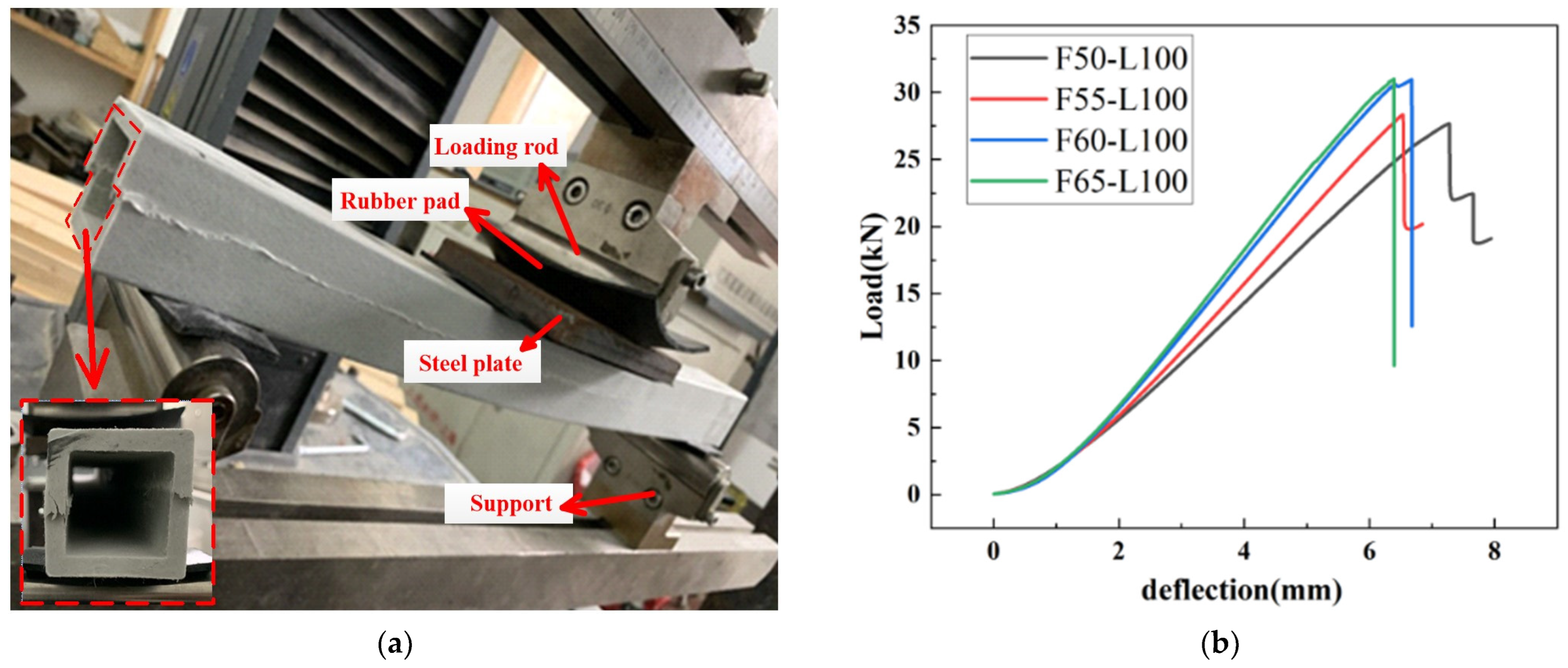
2.2. Static Bending Test Set-Up

Static bending tests are conducted beforehand to acquire the load-bearing capacity in order to determine load levels for the creep test. Under a constant temperature of 25 °C and relative humidity of 55%, the static three-point bending tests are conducted by MTS electronic universal testing machine, as shown in Figure 2. The loading rod and supports of the testing machine are set as cylindrical shapes of a diameter of 30 mm. To prevent local failure, rubber pads of 70 mm in length, 25 mm in width, and 3 mm in thickness, with Shore hardness of approximately 60, are placed at the loading rod and supports. Meanwhile, a square steel plate is placed at the loading rod. The tests are implemented at a displacement-controlled loading rate of 1 mm/min until specimen failure. Load and deflection data are automatically recorded by the testing machine at a recording frequency of 1 Hz.

2.3. Bending Creep Test Set-Up

Bending creep experiments are conducted for specimens with different fiber contents and load levels shown in Table 1, in an environment with a constant temperature of 25 °C and a relative humidity of 55%. As shown in Figure 2, the bending creep testing apparatus is designed based on the lever principle, with a ratio of 3.0 between the power arm and the resistance arm. The deflection variations of the specimens during the bending creep test process are recorded using dial indicators with a scale increment of 0.01 mm.
For the experimental procedure of the bending creep test, the required counterweights corresponding to the required load values are placed into the steel basket. Next, a jack is utilized to support the steel arm, and then the specimen is positioned on supports simulating simply supported conditions with a span of 400 mm. Subsequently, the position of the dial indicator is adjusted to ensure the pointer is vertically aligned at the top of the mid-span on the lower surface of the specimen. The moment the jack is released represents the initial of the creep test. During the initial ten minutes of the test, the readings of the dial indicator are recorded every minute. The phenomenon and deflection data are observed and recorded frequently at first and then the observation frequency reduces gradually with an increase in time. The recording continues until the specimens fail or the testing duration reaches 3000 h.

3. Results and Analysis

3.1. Static Bending Results

After 6 to 8 min of static three-point bending tests on the specimens, the square tube experiences sudden brittle shear failure on its web, accompanied by a noticeable noise. The load-deflection curves for the specimens are plotted in Figure 3b. It can be found that the GFRP tubes exhibit a linear property before failure and the ultimate load-bearing capacity increases with an increase in the fiber content. The ‘F50-L100’ and ‘F55-L100’ curves experience a sharp decline followed by a subsequent rise; this is because specimens with lower glass fiber content exhibit a degree of ductility. However, specimens with glass fiber content exceeding 60% exhibit reduced ductility upon failure. The ultimate load-bearing capacities for specimens F50-L100, F55-L100, F60-L100, and F65-L100 are 27.68 kN, 28.34 kN, 30.97 kN, and 31.01 kN, respectively. As shown in Figure 3a, the specimens exhibit shear failure, with the maximum shear force occurring at the web plate. This is attributed to the predominantly longitudinal fiber distribution in CFRP square tubes, with fewer transverse fibers, making them relatively weaker.

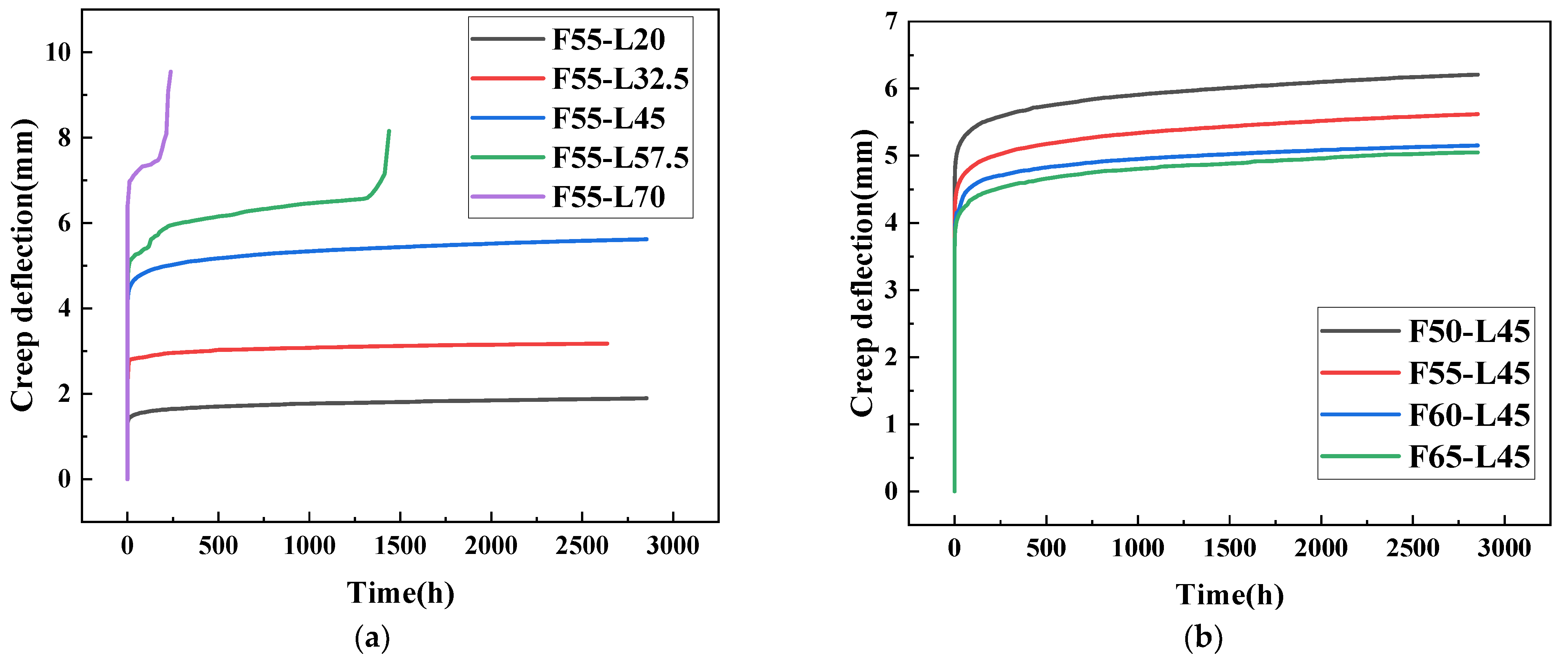
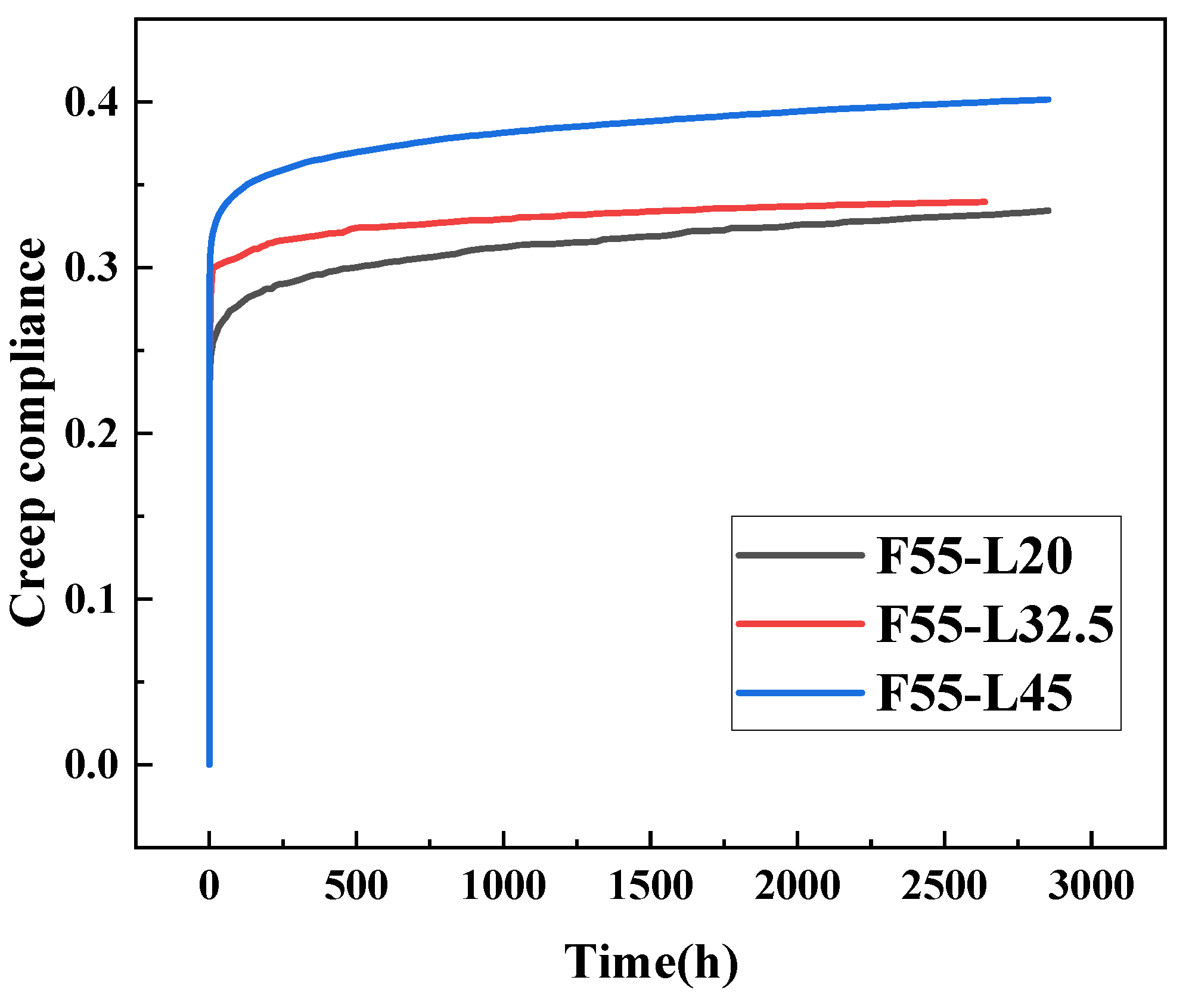
3.2. Bending Creep Results

Figure 4 displays the deflection-time curves for specimens with different load levels and fiber contents. The typical three-stage creep curves exhibit a gradually decreased creep rate during the initial stage, a constant creep rate in the second stage, and an accelerated creep rate until creep failure for the third stage [32]. For specimens under 57.5% and 70% load levels, creep failure occurs rapidly within 1500 h, whereas the rest specimens only stay in the second creep stage with a constant creep rate. This study primarily analyzes the first two creep stages obtained within the limited experimental duration. The initial static deflection (d), total deflection (Dt), creep deflection (C), and creep coefficient (Ci) of the GFRP pultrusion tubes with different load levels and fiber contents are listed in Table 3. The initial static deflections for F50, F55, F60, and F65 are recorded as 4.377 mm, 3.873 mm, 3.585 mm, and 3.498 mm. As shown in Figure 4a, specimens with fiber contents of 50%, 55%, 60%, and 65% all entered the second creep stage after approximately 150 h of the initial creep stage. The creep rates measured for F50-L45, F55-L45, F60-L45, and F65-L45 between 300 h and 3000 h were 1.81 × 10⁻⁴ mm/h, 1.22 × 10⁻⁴ mm/h, 8.15 × 10⁻⁵ mm/h, and 7.04 × 10⁻⁵ mm/h. Therefore, it can be concluded that, at the same load level, the total deflection of different GFRP pultrusion tubes is negatively correlated with the fiber content. As the load level gradually increases, GFRP pultrusion tubes begin to experience damage. Both the F55-L57.5 and F55-L70 curves allow for a complete observation of the three stages of creep. The GFRP pultrusion tube was subjected to a 57.5% load level transition in the third stage, the accelerated creep stage, after undergoing the second creep stage. Creep failure occurs between 1145.17 h and 1253.05 h, with a failure time of 107.88 h. In contrast, at the 70% load level, the failure time is significantly shorter, transpiring between 468.52 h and 478.36 h with a failure time of 9.84 h. This outcome reveals that increasing the load level substantially reduces the duration of the creep second stage until the second stage ceases to manifest. As illustrated in Figure 4b, the observed creep rates for F55-C20, F55-C32.5, and F55-C45 between 300 h and 3000 h were 7.78 × 10⁻⁵ mm/h, 1.07 × 10⁻⁴ mm/h, and 1.22 × 10⁻⁴ mm/h. Therefore, it can be inferred that for a GFPR pultrusion tube with the same fiber content, the total deflection has a positive correlation with the load level. These data indicate that, at the same load level, specimens of square tubes with higher fiber content generally exhibit better creep resistance compared to those with lower fiber content. However, as the fiber content further increases, the impact on the specimen’s resistance to creep gradually diminishes. For GFRP pultrusion tubes with the same fiber content, specimens exhibit more noticeable creep when subjected to higher load levels. When the load level exceeds 57.5%, specimens experience creep failure, indicating that the load level significantly affects the creep behavior of GFRP pultrusion tubes.
When comparing the deflection of specimens at static and creep failure, it can be observed that the deflection at the time of failure generally falls within the range of 6.5 mm to 7.5 mm. This suggests that the specimens experienced elastic–plastic behavior during the creep loading period, where plastic deformation led to an increase in deflection. This may imply that the specimens underwent some degree of plastic deformation, rather than solely elastic deformation, resulting in similar deflection values.
To assess the creep performance of GFRP pultrusion tubes under three different load levels of 20%, 32.5%, and 45%, creep compliance is employed as the indicator. The creep compliance is defined as the ratio of creep deformation to the constant external force applied to the specimen [33]. It can be expressed as follows:
D c ( t ) = C F
where Dc(t) represents creep compliance, C stands for creep deformation, and F represents the applied load on the specimen. Figure 5 shows the relationship curves between creep compliance and the time for a GFRP pultrusion tube with a 55% fiber content at load levels of 20%, 32.5%, and 45%. It can be observed that the creep compliance curves for F55-L20, F55-L32.5, and F55-L45 in Figure 5 are very close to each other. This suggests that GFRP pultrusion tubes exhibit approximately linear viscoelastic behavior in creep performance at load levels less than 45%.
The failure modes of GFRP pultrusion tubes fall into two categories: shear failure (Figure 6a) and overall bending failure (Figure 6b). With increasing load levels, the transition from web shear failure to bending failure becomes apparent. Shear failure is due to web plate deformation under applied forces, whereas overall bending failure can be explained by plastic hinge concepts. During the entire bending creep test, a constant force at the specimen’s center results in a constant bending moment (M). However, the GFRP pultrusion tube’s ultimate bending moment (Mu) gradually decreases due to creep-induced damage during the test. When Mu equals M, plastic hinges form at cross-sections of the GFRP pultrusion tube, transforming the structure into a single-degree-of-freedom system in static conditions, which reduces the load-bearing capacity. Therefore, at load levels below 70%, Mu takes longer to decrease to match M than the time for web shear failure to occur, leading to shear failure. However, when the load level reaches 70%, the time for Mu to match M starts to approach or become less than the time needed for web deformation to induce shear failure, resulting in overall bending failure.

4. Creep Predictions

4.1. Prediction of Creep Deflection

The creep behavior of the GFRP pultrusion tube under low load levels (below 45%) is simulated and analyzed using two well-established phenomenological models, namely the Bailey–Norton model (Equation (2)) and the Findley model (Equation (3)). These two models are specifically designed to model and analyze only the initial and second stages of creep [34].
D ( t ) = C 1 F C 2 t C 3
D ( t ) = d i + a t N
where D(t) represents the total deflection; F denotes the force applied to the GFRP pultrusion tube at the midpoint during the bending creep test; t stands for the duration of creep; C1, C2, and C3 represent undermined constants [35]; di denotes the initial static deflection; a represents the creep amplitude; and N is the time exponent. The creep amplitude exhibits a proportional relationship with the applied force and temperature, whereas the time exponent, N, is considered to be a function of the material’s moisture content and temperature [36]. Since all bending creep tests are conducted under identical humid-heat conditions, it can be considered that the creep amplitude is solely dependent on the applied load level, and the time exponent can be regarded as a material constant.
Figure 7a shows the results of fitting and analyzing the creep deflection curves of GFRP pultrusion tubes with a 55% fiber content using Equation (2). The results indicate that the Bailey–Norton model provides a better fit for the creep deflection curve of the GFRP pultrusion tube. Although the Bailey–Norton model can be used to perform fitting analysis on GFRP pultrusion tubes under different load levels, it is not suitable for fitting analysis of the time-varying total deflection curves of GFRP pultrusion tubes due to the lack of consideration for the influence of initial static deflection in Equation (2).
Figure 7b presents the fitting analysis results of the creep deflection curves of GFRP pultrusion tubes with 55% fiber content using Equation (3). It is worth noting that Equation (3) consists of two parts: the initial static deflection (di) and the time-dependent creep deflection (atN). As a result, the Findley model performs exceptionally well in fitting the time-dependent total deflection curves. The test curves closely align with their corresponding fitted curves. Similarly, Table 4 summarizes the results of the parameters fitted by the Findley model, where the maximum error between the fitted values and test values for the time-dependent total deflection curves is only 0.4%. This also demonstrates the excellent fitting performance of the Findley model for the various time-dependent total deflection curves. However, it is important to highlight that the Findley model cannot account for the influence of load levels and is therefore suitable only for fitting time-dependent total deflection curves at specific load levels.
Figure 8 illustrates the fitting and prediction results for GFRP pultrusion tubes at load levels of 20%, 32.5%, and 45% using the Bailey–Norton and Findley models. The research findings indicate that while the Bailey–Norton model can predict creep deflection for load levels below 45%, there is a certain degree of disparity between the predicted curves and the observed creep deflection curves at load levels of 20% and 32.5%, suggesting suboptimal prediction accuracy. Conversely, the Findley model demonstrates fitting results that closely resemble the experimental curves for load levels below 45%.

4.2. Prediction of Creep Life

Due to the rapid occurrence of creep failure once GFRP pultrusion tubes enter the third stage of creep, estimating creep failure time based on the deflection at the end of the second stage of creep poses a considerable risk. Therefore, this study adopts the deflection at the end of the first stage of creep as the basis for estimating creep failure time for specimens under different load levels. The deflection values at the end of the first stage for F55-L20, F55-L32.5, and F55-L45 are 1.791 mm, 2.885 mm, and 5.069 mm, respectively. Using this method inevitably leads to a conservative estimate of creep life but ensures a safety margin in the final results. Given that the fitting curves of the Findley model closely resemble the experimental curves for load levels below 45%, the Findley model is employed for predicting the creep life of GFRP pultrusion tubes.
Taking the creep life calculation of specimens under a 20% load level as an example, the parameters for F55-L20 are substituted into Equation (3). Setting the value of F as 5.668 kN and D(F, t) as 1.791 mm, the calculated result shows that the value of t is 1.97 × 10¹¹ h. Similarly, using a similar approach and considering the predicted results at load levels of 20%, 32.5%, and 45%, as well as the experimental results at 57.5% and 70% load levels, along with the inevitable points the curve passes through, a total of six key points on the creep life prediction curve are obtained: (0, +∞), (20%, 1.97 × 10¹¹), (32.5%, 3.98 × 10⁷), (45%, 6.67 × 10⁶), (57.5%, 107.88), and (70%, 9.84).
Based on the positions of six key points mentioned above in the coordinate system, it can be hypothesized that a curve resembling an exponential function, y = aebx + cedx, exists in the coordinate system. Using the least squares method to calculate the best estimates of model parameters a, b, c, and d in order to minimize the objective function between model predictions and specimen data points. For each data point, the residual is defined as e i = y i a e b x i c e d x i . The objective function is defined as the sum of squared residuals, i.e., S = i = 1 n e i 2 . Subsequently, numerical optimization algorithms are employed to compute the partial derivatives of the objective function and set them to zero, aiming to determine the parameter values that minimize the sum of squared residuals. Through the process of exponential curve fitting, the creep life prediction formula (Equation (4)) is successfully derived.
T = 9.61 × 10 7 e 167.4 L + 7.43 × 10 5 e 24.9 L
Through the calculation of Equation (4), we find that the failure time predicted by the creep life prediction equation closely matches the experimental values. This demonstrates the suitability and accuracy of the creep life prediction model developed using this method. Moreover, there is a substantial variation in creep life among specimens tested at different load levels. As the load level decreases by 20%, from 57.5% to 20%, the creep life increases significantly. Notably, when the load level is below 20%, the predicted values on the curve become exceedingly large, implying the unlikelihood of experiencing creep failure at such levels. Once the creep life prediction curve is established, it serves as a valuable tool for predicting the creep life of structures at any load level. In addition, it aids in determining the maximum load level that a structure can endure while adhering to the desired service life, effectively safeguarding against creep failure.

5. Relevance of this Research for Practical Implementation

GFRP is widely used in various fields, including bridges, construction, and marine engineering, and plays an irreplaceable role in specific environments such as chemical corrosive settings, high-chloride areas with salt corridor frameworks, marine structures, and lightweight bridges in mountainous regions with challenging transportation conditions. However, the use of GFRP as load-bearing components currently lacks corresponding regulatory requirements. Consequently, it often involves oversized cross-sectional designs, leading to increased costs and resource wastage in practical applications.
This study investigates the creep behavior of GFRP pultrusion tubes with different load levels and fiber contents. It involves fitting and analyzing experimental results and predicting specimen lifespans using the Findley model. Such research aids in component designs in engineering applications, reducing the cost increase associated with enlarging the cross-section while still meeting performance requirements.

6. Conclusions

This study aims to examine the flexural creep behavior of GFRP composite pultrusion tubes. When the load level does not exceed 45%, the GFRP pultrusion tube exhibits linear viscoelastic creep behavior. In comparison to square tubes with low glass fiber content, those with higher glass fiber content display greater ultimate load capacity, smaller creep deflection, and longer time to creep failure under the same load. Moreover, square tubes with higher glass fiber content demonstrate superior creep resistance compared to those with lower glass fiber content. At load levels of 20% and 32.5%, the Findley model provides a good fit for creep curves. Using the experimental results and the Findley model, a predictive formula for the creep life of GFRP square tubes has been derived. The specific conclusions are as follows:
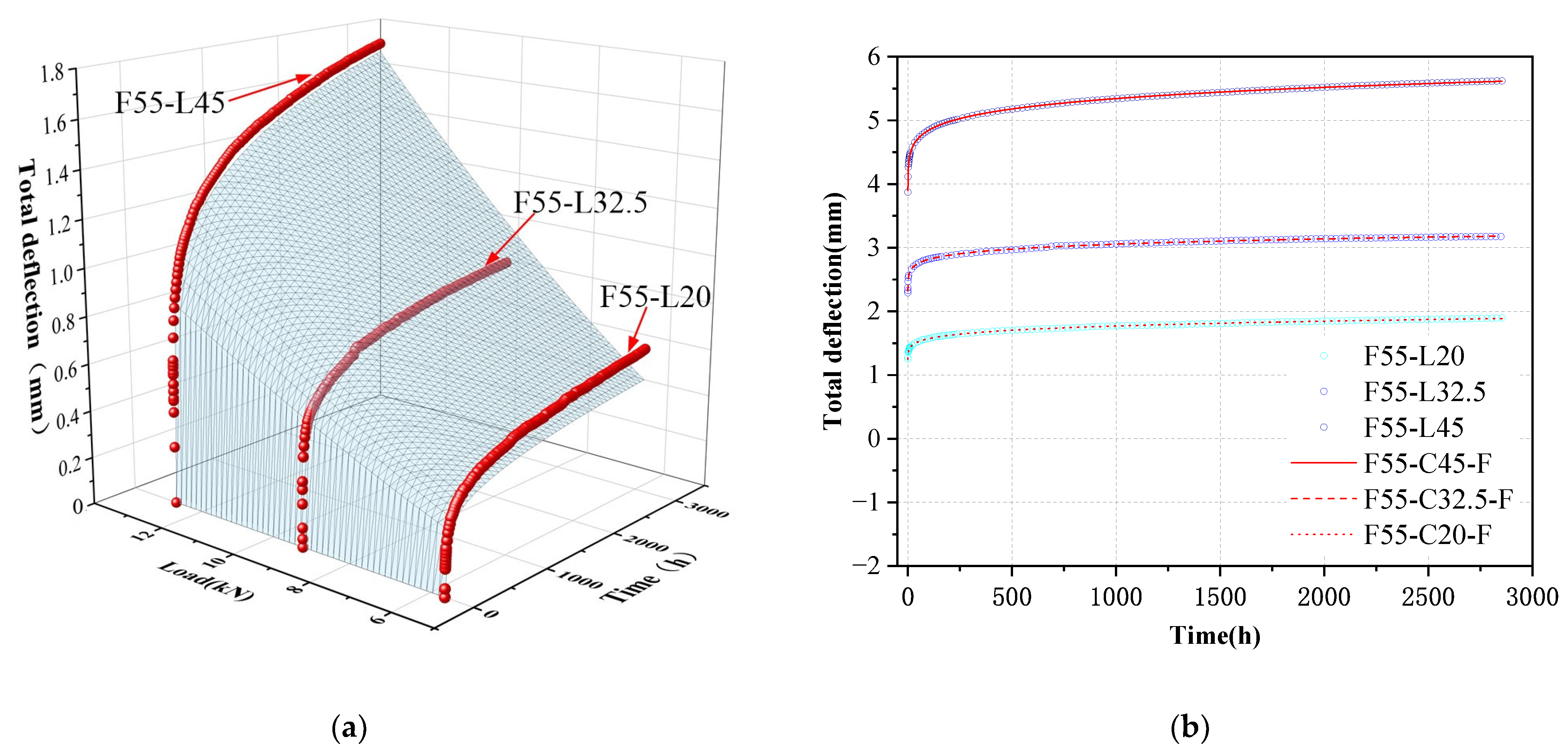
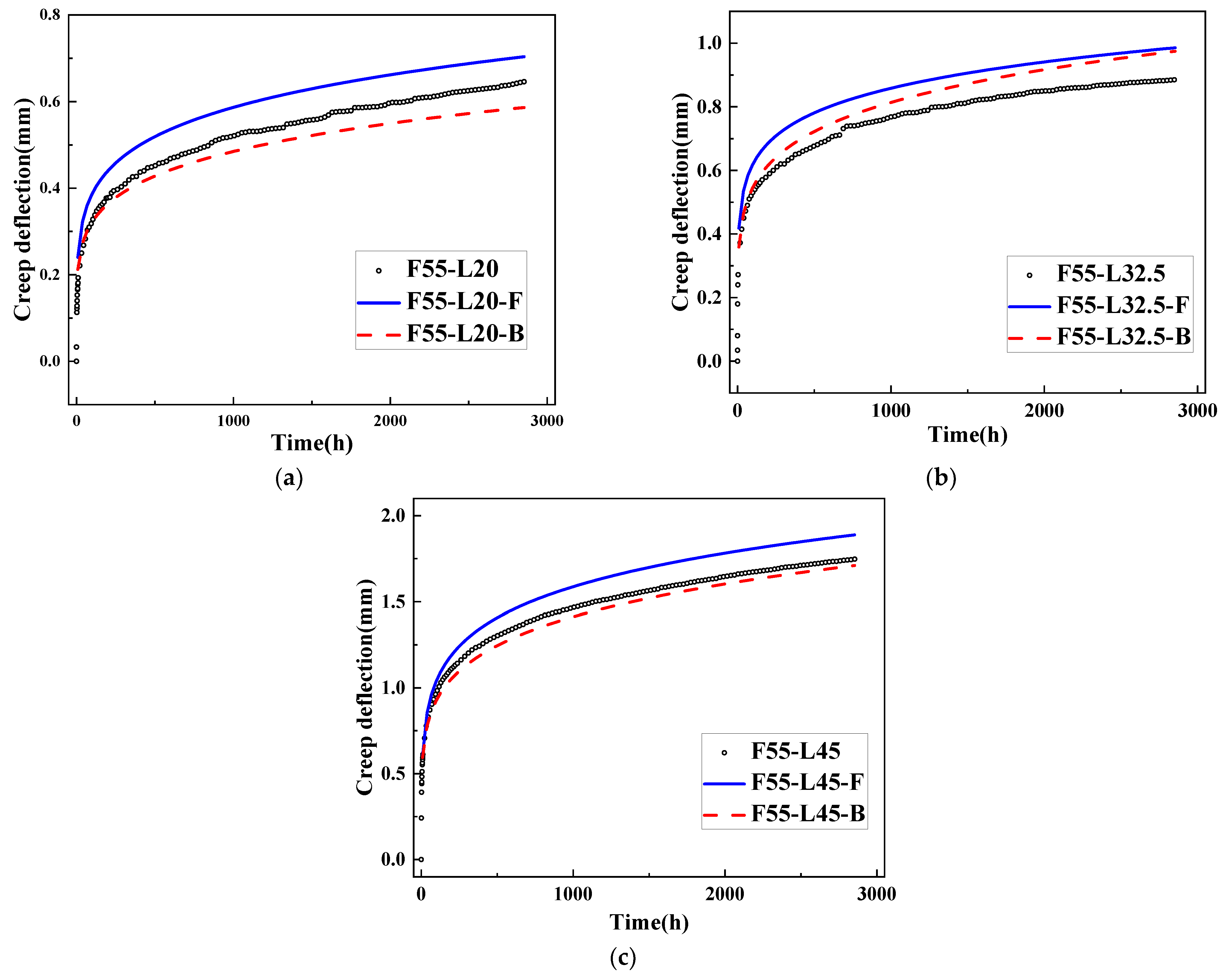
  • The results reveal that the creep behavior of the GFRP pultrusion tubes exhibits linear viscoelasticity when the load level is below 45%. In terms of creep deflection, the Findley model exhibits superior fitting performance compared to the Bailey–Norton model for the creep curves at 20% and 32.5% load levels. The maximum error between its total deflection curve’s fitted values and the test values is only 0.4%. This is because the Findley model takes into account not only the deflection changes during the creep stage but also the initial static deflection of the specimens.
  • After establishing a clear definition of the creep stages, a distinct transition point from the primary creep stage to the second creep stage at 300 h can be prominently observed for the load levels of 20%, 32.5%, and 45%. Creep failure is observed in specimens subjected to load levels of 57.5% and 70%, with corresponding failure times of 107.88 h and 9.84 h. As the load level increases, the specimen’s time to failure significantly decreases, indicating that the load level has a crucial impact on the creep behavior of GFRP pultrusion tubes. Furthermore, with increasing load levels, the failure mode gradually shifts from shear failure of the web to overall bending failure. By comparing the time required for Mu to decrease to M and the time required for shear creep of the web leading to shear failure, a reasonable explanation can be provided for distinct failure modes exhibited at different load levels. When the time required for Mu to decrease to match M is longer than the time needed for web shear failure to occur, shear failure takes place. Conversely, when the time for Mu to decrease to match M begins to approach or becomes less than the time needed for web deformation to induce shear failure, overall bending failure occurs.
  • Based on experimental results and the Findley model, a method has been proposed for predicting the creep life of GFRP composite pultrusion tubes. This method allows for the derivation of predictive formulas for creep life, and computed results show a good agreement with experimental findings. However, since this method solely considers the influence of load levels, further research is needed in the future to investigate the impact of other parameters (e.g., temperature and humidity) on creep life.

Author Contributions

Methodology, H.F.; Validation, Y.W. and C.Q.; Investigation, K.C.; Resources, C.Q.; Data curation, Y.W.; Writing—original draft, K.C.; Writing—review & editing, P.W.; Supervision, H.F. and P.W. All authors have read and agreed to the published version of the manuscript.

Funding

This research is financially supported by the National Natural Science Foundation of China (No. 52108220).

Data Availability Statement

Data available on request from the authors.

Conflicts of Interest

We declare that we have no conflict of interest to this work.

References

  1. National Natural Science Foundation of China, Chinese Academy of Sciences. Development Strategy of Disciplines in China: Civil Engineering and Engineering Mechanics; Science Press: Beijing, China, 2016.
  2. Shen, G.L. Mechanics of Composite Materials; Tsinghua University Press: Beijing, China, 1996. [Google Scholar]
  3. Hu, Q.; Duan, Y.; Liu, Z.; Zheng, X.; Xu, Z. Current status of carbon fiber reinforced polymer composites recycling and re-manufacturing. Compos. Part B Eng. 2020, 193, 108053. [Google Scholar]
  4. Chen, R.; Cheng, L.; Gu, J.; Yuan, H.; Chen, Y. Research progress in chemical recovery technology of fiber-reinforced polymer composites. CIESC J. 2023, 74, 981–994. [Google Scholar]
  5. Wu, J.; Zhu, Y.; Li, C. Experimental Investigation of Fatigue Capacity of Bending-Anchored CFRP Cables. Polymers 2023, 15, 2483. [Google Scholar] [CrossRef] [PubMed]
  6. Kim, Y.; Oh, H. Comparison between Multiple Regression Analysis, Polynomial Regression Analysis, and an Artificial Neural Network for Tensile Strength Prediction of BFRP and GFRP. Materials 2021, 14, 4861. [Google Scholar] [CrossRef]
  7. Xian, G.; Guo, R.; Li, C. Combined effects of sustained bending loading, water immersion and fiber hybrid mode on the mechanical properties of carbon/glass fiber reinforced polymer composite. Compos. Struct. 2022, 281, 115060. [Google Scholar] [CrossRef]
  8. Shi, J.; Huang, Z. Application of composite materials in marine vessels. Glass Fiber Reinf. Plast./Compos. 2012, 2, 269–273. [Google Scholar]
  9. Yue, Q.; Yang, Y. Review of durability research on fiber-reinforced composite strengthened structures. J. Build. Struct. 2009, 30, 8–15. [Google Scholar]
  10. Teng, J. New material composite structures. J. Civ. Eng. 2018, 51, 1–11. [Google Scholar]
  11. Ye, L.; Feng, P. Application and development of FRP in engineering structures. J. Civ. Eng. 2006, 3, 24–36. [Google Scholar]
  12. Mario, F.S.; Augusto, M.G.; João, R.C.; Nuno, S. Flexural creep response of pultruded GFRP deck panels: Proposal for obtaining full-section viscoelastic moduli and creep coefficients. Compos. Part B Eng. 2016, 98, 213–224. [Google Scholar]
  13. Bottoni, M.; Mazzotti, C.; Savoia, M. Creep tests on GFRP pultruded specimens subjected to traction or shear. Compos. Struct. 2014, 108, 514–523. [Google Scholar] [CrossRef]
  14. Zou, X.X.; Lin, H.W.; Feng, P.; Bao, Y.; Wang, J.Q. A review on FRP-concrete hybrid sections for bridge applications. Compos. Struct. 2021, 262, 113336. [Google Scholar] [CrossRef]
  15. Scott, D.W.; Zureick, A.H. Compression creep of a pultruded e-glass/vinylester composite. Compos. Sci. Technol. 1998, 58, 1361–1369. [Google Scholar] [CrossRef]
  16. Liu, X. Research on Long-Term Performance and Prediction Methods of FRP Pultruded Profiles in Marine Environment. Ph.D. Thesis, Tsinghua University, Beijing, China, 2021. [Google Scholar]
  17. Lu, Z.; Zhang, Q.; Cao, Y.; Luo, F.; Liu, M. Calculation method for flexural behavior of concrete beams strengthened with FRP profiles. J. Wuhan Univ. Technol. 2021, 43, 54–58. [Google Scholar]
  18. Lu, Z.; Luo, F.; Zhang, Q.; Cao, Y.; Liu, M. Experimental study on flexural capacity of concrete beams strengthened with GFRP profiles. J. Wuhan Univ. Technol. (Transp. Sci. Eng. Ed.) 2023, 274, 1–8. [Google Scholar]
  19. Liu, D.Q. Mechanical Performance Study of CFPR Angle Steel Tube Concrete Pure Bending Members with Embedded I-Shaped CFRP Profiles. Master’s Thesis, Shenyang Jianzhu University, Shenyang, China, 2019. [Google Scholar]
  20. Fei, H.Y.; Zhao, J.Y.; Cui, B.J.; Chen, X.B.; Yan, C.R. Performance study of continuous glass fiber mat/polyester insulation profiles. Insul. Mater. 2020, 53, 6–9. [Google Scholar]
  21. Feng, X.; Li, G.C.; Yang, Z.J.; Cao, W.Z. Study on bidirectional eccentric compression performance of long columns with square steel tube and embedded I-shaped CFRP profiles. Adv. Struct. Steel Res. 2021, 23, 32–42+52. [Google Scholar]
  22. Li, A. Experimental Study and Theoretical Analysis of Flexural Performance of GFRP Profile-Concrete Composite Beams. Master’s Thesis, Hunan University of Science and Technology, Xiangtan, China, 2018. [Google Scholar]
  23. Zhang, Z.W. Study on Flexural Performance of FRP Profile-Concrete Composite Beams. Master’s Thesis, Yangzhou University, Yangzhou, China, 2022. [Google Scholar]
  24. Li, X.; Liu, W.; Fang, H.; Huo, R.; Wu, P. Flexural creep behavior and life prediction of GFRP-balsa sandwich beams. Compos. Struct. 2019, 224, 111009. [Google Scholar] [CrossRef]
  25. Li, X.; Liu, W.; Fang, H.; Huo, R.; Wu, P. Flexural creep behavior of web reinforced GFRP-balsa sandwich beams: Experimental investigation and modeling. Compos. Part B 2020, 196, 108150. [Google Scholar] [CrossRef]
  26. Dutta, P.K.; Hui, D. Creep rupture of a GFRP composite at elevated temperatures. Compos. Struct. 2000, 76, 153–161. [Google Scholar] [CrossRef]
  27. Zhang, X.G.; Zhang, Y.B. Study on the bending creep behavior of glass fiber reinforced vinyl resin composite. Aviat. Manuf. Technol. 2013, 45, 71–72+79. [Google Scholar]
  28. Xu, B.; van den Hurk, B.; Lugger, S.J.D.; Liu, T.; Blok, R.; Teuffel, P. Effect of environmental humidity on the creep behavior of flax fiber-reinforced polymer composites. Polym. Compos. 2023, 44, 6108–6121. [Google Scholar] [CrossRef]
  29. Pavlović, A.; Donchev, T.; Petkova, D. Analytical Estimation of the Creep Behaviour of Basalt FRP Bars Below the Creep Rupture Limit. Build. Future Durable Sustain. Resilient 2023, 349, 739–746. [Google Scholar]
  30. Alhayek, A.; Syamsir, A.; Supian, A.B.M.; Usman, F.; Najeeb, M.I.; Asyraf, M.R.M. A Mathematical Model of Flexural-Creep Behaviour for Future Service Expectancy of a GFRP Composite Cross-Arm with the Influence of Outdoor Temperature. Fibers Polym. 2023, 24, 2425–2437. [Google Scholar] [CrossRef]
  31. Supian, A.B.M.; Syamsir, A.; Alhayek, A.; Asyraf, M.R.M.; Itam, Z. The Reduction Factor of Pultrude Glass Fibre-Reinforced Polyester Composite Cross-Arm: A Comparative Study on Mathematical Modelling for Life-Span Prediction. Material 2023, 16, 5328. [Google Scholar]
  32. Shi, H.; Liu, W.; Fang, H. Damage characteristics analysis of GFRP-Balsa sandwich beams under four-point fatigue bending. Compos. Part A Appl. Sci. Manuf. 2018, 109, 564–577. [Google Scholar] [CrossRef]
  33. Zhang, F.; Liu, W.; Ling, Z.; Fang, H.; Jin, D. Mechanical performance of GFRP-profiled steel sheeting composite sandwich beams in four-point bending. Compos. Struct. 2018, 206, 921–932. [Google Scholar] [CrossRef]
  34. Chen, Z.; Yan, N.; Deng, J.; Smith, G. Flexural creep behavior of sandwich panels containing Kraft paper honeycomb core and wood composite skins. Mater. Sci. Eng. Struct. Mater. Prop. Microstruct. Process. 2011, 528, 5621–5626. [Google Scholar] [CrossRef]
  35. Tweedie, C.A.; Van Vliet, K.J. Contact creep compliance of viscoelastic materials via nanoindentation. J. Mater. Res. 2006, 21, 1576–1589. [Google Scholar] [CrossRef]
  36. Du, Y.; Yan, N.; Kortschot, M.T. An experimental study of creep behavior of lightweight natural fiber-reinforced polymer composite/honeycomb core sandwich panels. Compos. Struct. 2013, 106, 160–166. [Google Scholar] [CrossRef]
Figure 1. Manufacturing process of GFRP pultruded tubes and constituent material and size of GFRP pultrusion tube.
Buildings 13 02714 g001
Figure 2. Loading device for bending creep test of GFRP pultrusion tube.
Buildings 13 02714 g002
Figure 3. Loading device and load-deflection curves for static bending tests of CFRP pultrusion tube with different fiber contents. (a) Loading device; (b) load-deflection curves.
Buildings 13 02714 g003
Figure 4. Deflection-time curves for the GFRP tube with different load levels and fiber contents. (a) Effect of load level; (b) effect of fiber content.
Buildings 13 02714 g004
Figure 5. Creep compliance curve of pultrusion tube with 55% glass fiber content.
Buildings 13 02714 g005
Figure 6. Creep failure mode for the GFRP tube. (a) 57.5% load level; (b) 70% load level.
Buildings 13 02714 g006
Figure 7. Fitting models for the creep deflection curves. (a) Bailey–Norton model; (b) Findley model.
Buildings 13 02714 g007
Figure 8. Fitting results of the Bailey–Norton model (-B) and the Findley model (-F) for the creep deflection curves of GFRP pultruded tubes. (a) 20% load level; (b) 32.5% load level; (c) 45% load level.
Buildings 13 02714 g008
Table 1. Details of static bending test specimens.
Specimen IDNumber of SpecimensFiber Content (%)Load Level (%)Load (kN)
F50-L10055010027.68
F55-L10055510028.34
F60-L10056010030.97
F65-L10056510031.01
Table 2. Details of bending creep test specimens.
Specimen IDNumber of SpecimensFiber Content (%)Load Level (%)Load (kN)
F55-L20555205.67
F55-L32.555532.59.21
F55-L455554512.75
F55-L57.555557.516.30
F55-L705557019.84
F50-L455504512.46
F60-L455604513.94
F65-L455654513.95
Table 3. Summary of the creep test results.
(a) Creep test results of square tube with different glass fiber contents under 45% load level
Specimen IDStatic Deflection(mm)Total Deflection (mm)Creep Deflection (mm)Creep Coefficient
F50-L454.3776.2081.8310.42
F55-L453.8735.6201.7470.45
F60-L453.5855.1551.5700.44
F65-L453.4985.0501.5500.44
(b) Creep test results of square tube with 55% glass fiber content
Specimen IDStatic Deflection (mm)Total Deflection (mm)Creep Deflection (mm)Creep Coefficient
F55-L201.2501.8960.6460.51
F55-L32.52.2913.1760.8850.39
F55-L453.8735.6201.7470.45
F55-L57.54.4576.5882.1310.48
F55-L706.3357.4651.1300.19
Table 4. Summary of the fitting results of various parameters in the Findley model.
Specimen IDdiaNDeDFError (%)
F55-L201.1040.2300.1541.8961.88770.43
F55-L32.51.8570.6160.0963.1763.18250.20
F55-L453.1541.0110.1125.6205.61410.10
Disclaimer/Publisher’s Note: The statements, opinions and data contained in all publications are solely those of the individual author(s) and contributor(s) and not of MDPI and/or the editor(s). MDPI and/or the editor(s) disclaim responsibility for any injury to people or property resulting from any ideas, methods, instructions or products referred to in the content.

