Abstract
Viscous dampers have proven to be effective in enhancing the seismic performance of existing structures. Despite this, there is still a need for rapid and simplified design methods and formulae for viscous dampers that can take into account the elastic–plastic performance of structures. This study introduces a retrofit design method for existing structures using viscous dampers, based on the concept of uniform damping ratio (UDR), with the aim of fully utilizing each damper. The UDR concept assumes that each damper in the structure provides the same UDR when subjected to seismic excitations of identical intensity. In this method, the first step involves defining the equivalent damping ratio (EDR) of the damper. Then, based on the capacity spectrum of the structure, the response mitigation ratio can be determined, which helps to determine the additional EDR required from the dampers. Once the UDR and additional EDR from the viscous damper have been determined, the parameters of the dampers at each story can be rapidly obtained. To demonstrate the effectiveness of this method, a six-story reinforced concrete frame was utilized as a benchmark structure. A comparison between this UDR-based approach and a traditional design approach was also conducted. The study findings reveal that the UDR concept enables the maximum utilization of energy dissipation capacity of viscous dampers installed in the structure, leading to a more effective and economical design approach.
1. Introduction
The effective energy dissipation device known as the viscous damper has been extensively utilized in civil engineering because of its efficiency [1,2,3,4,5,6]. Utilizing viscous dampers for retrofitting existing structures has been verified as an efficient technique [7,8,9,10,11,12,13]. To take full advantage of the energy dissipation capacity of viscous dampers, various design methods have been proposed. Gluck et al. [14] used a linear quadratic regulator as a tool in a control optimization method to design the linear viscous damper. This method optimized the parameters, but the location of the viscous damper was not considered. To optimize the location of viscous dampers, a variety of design methods have been proposed by a number of researchers [15,16,17,18,19,20,21,22,23,24,25,26,27]. Additional researchers have augmented the algorithms, optimizing the design procedure for greater efficiency [28,29,30,31]. Optimal algorithms can reach target structural performance, but they are too complex to be applied in practical engineering. Moreover, iterative calculations are unavoidable and can be quite time-consuming, especially in the case of dynamic analysis. There is scope for further optimization of the algorithm in terms of its rate of convergence.
Apart from the design approaches of viscous dampers based on an optimal algorithm, a variety of direct design methods have been proposed. The manual developed by Japan Society and Seismic Isolation (JSSI) [32] gives a classic design approach based on the elastic response reduction curve, in which the parameters of viscous dampers are determined according to the story’s stiffness. However, the nonlinear behavior of the members is not considered, which may overestimate the energy dissipation capacity of the dampers [9]. A design method based on the capacity spectrum method (CSM) was introduced by Kim et al. [33] to obtain the parameters of the viscous dampers that considers the plastic characteristics of the structure. Uetani et al. [34] simplified the structural model and designed the parameters of viscous dampers based on the responses of elastic static analysis. Yet the method could be adjusted for improved feasibility if inelastic responses were taken into consideration. A five-step design approach was proposed by Silvestri et al. [35] to guide engineers through the design of the viscous dampers according to their target performance. The method required a numerical time–history analysis to estimate the responses. Palermo et al. [36] improved this five-step approach by estimating the structural peak velocities more accurately and efficiently. This method aimed to give a preliminary design and to guide engineers who are not familiar with viscous dampers. A direct procedure was presented to determine the required supplemental equivalent damping ratio (EDR) of viscous dampers by Landi et al. [37,38]. This procedure was utilized to explore the influence of the distribution of viscous dampers on the seismic responses of the retrofit structures [39].
To evaluate the effectiveness of viscous dampers, the concept of a damping ratio is proposed. By calculating the damping ratio provided by the viscous dampers, structural engineers can accurately assess the mitigation effect of viscously damped structures [40,41,42]. Although the damping ratio provided by viscous dampers is a crucial parameter, the connection between the damping ratio and the performance target considering the plastic characteristics of the structure has not been addressed in previous design methods, which can make the design process iterative and repetitive, requiring a significant amount of time to reevaluate the seismic performance of viscously damped structures [23,43,44]. Therefore, the retrofit design approach for existing structures that employ viscous dampers must be further developed to address these considerations.
This study presents a simplified design process for retrofitting existing structures with viscous dampers, which is founded on the notion of the uniform damping ratio (UDR). The UDR notion assumes that each damper in the structure has an equivalent damping ratio (EDR) when subjected to an external excitation, thus ensuring that all dampers installed have the necessary energy-dissipation capability. The design procedure for a single viscous damper begins with the definition of its effective damping ratio (EDR). The seismic performance of the original structure is evaluated using the capacity spectrum method (CSM), and an approach to estimate the EDR of the primary structure within the CSM framework is provided. The proposed design method for retrofitting the seismic performance of a structure can be determined by considering the original and target structural seismic performance. An equivalent single degree of freedom (SDOF) system representation is used to estimate the uniform damping ratio (UDR) of the viscous dampers to meet the target structural performance. This method is then employed to calculate the damping forces of the dampers based on the UDR and the required additional response mitigation ratio (RMR). Here, the application of this design procedure is demonstrated using a six-story reinforced concrete (RC) frame structure. The proposed design procedure is then compared to the classic method outlined in the JSSI Manual to assess its effectiveness and performance [32].
2. Uniform Damping Ratio-Oriented Design Method
An optimal design approach for a damped structure utilizing viscous dampers aims to effectively determine the damper parameters to achieve the desired seismic performance of the structure while fully utilizing the energy dissipation capacity of each damper. Typically, the energy dissipation capacity of an installed damper is represented by its EDR [45]. Therefore, the UDR concept is proposed, which preliminarily assumes the EDR of each damper to be uniform under external excitation. Based on the UDR concept, the dampers are expected to fully perform their capacity to dissipate the input seismic energy in this study. The notations employed in this study are defined in Table 1.

Table 1.
Notations.
2.1. Basic Concept of EDR for Single Viscous Damper
A viscous damper is a kind of hydraulic device that takes advantage of the viscosity of a fluid to dissipate the input energy. The ideal viscous fluid is able to dissipate energy and cannot store energy at all, which does not exist in reality. For general dampers, silicon oil is typically selected as the viscous material. However, silicon oil has great compressibility, which leads to the dynamic stiffness of dampers under vibration processes. The dynamic stiffness depends on the type of silicon oil, the frequency of excitation, and the size of the valve. For products produced by different manufacturers, stiffness varies. According to an experimental study, dynamic stiffness is related to the damping coefficient of the damper as follows [32]:
where represents the dynamic stiffness, represents the dynamic stiffness coefficient, and represents the damping coefficient.
As the dampers can both store and dissipate energy under vibration processes, the Maxwell model can be used [46]. The Maxwell model consists of a spring element and a damping element, which are depicted in Figure 1. The restoring force of the Maxwell model is shown in Equation (2):
where is the damping exponent of the viscous damper, is the output force of the Maxwell model, is the relative deformation of the spring element, and is the relative velocity of the damping element.
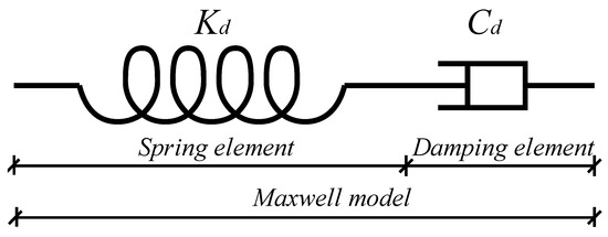
Figure 1.
Maxwell model.
The total deformation of the Maxwell model, , comprises the deformation of the spring element and the damping element:
where is the total deformation of the Maxwell model and is the deformation of the damping element.
Therefore, the EDR of a single damper can be defined according to the concept of EDR in structural dynamics [47]. The most common method for defining the EDR is to make the energy dissipated by the damper in a vibration cycle equal to an equivalent viscous system, which is given by the following equation [45]:
where represents the EDR of the viscous damper, is the energy dissipated by the damper in one cycle, and is the maximum strain energy of the damper structure in one cycle.
For most kinds of viscous dampers used for resisting seismic excitation, the damping exponent is commonly in the range of 0.1~0.4. Figure 2 shows a typical hysteresis curve of a nonlinear viscous damper with a damping exponent of 0.2. For practical engineering, it would be complicated to calculate the dissipated and restored energy of the viscous damper. To simplify the calculation, a simplified parallelogram encompassing the hysteresis curve of the damper is introduced, which is represented by the dashed line in Figure 2. The energy dissipation capacity of the viscous damper can be approximately obtained by the area of the simplified parallelogram.
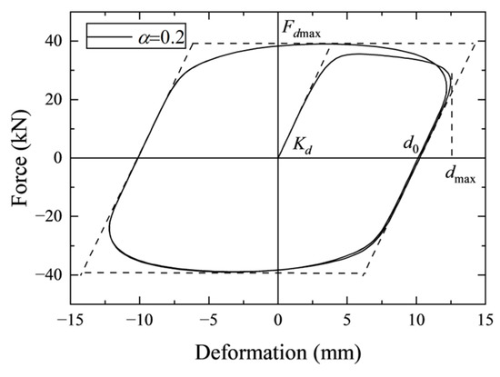
Figure 2.
A typical hysteresis curve of a nonlinear viscous damper.
To determine if the approximation of the calculation of energy dissipation is acceptable, the area error between the ideal hysteresis curve and the simplified parallelogram is explored. First, without considering the dynamic stiffness of the damper, namely and , the hysteresis curve is plotted, as shown in Figure 3. The area of the hysteresis curve can be calculated as follows [48]:
where is the natural circular frequency of the system with dampers, is the maximum deformation of the damping element in one cycle, and is the gamma function. Without considering the dynamic stiffness of damper , the simplified parallelogram becomes rectangular, which is also shown in Figure 3. The area of the parallelogram can be obtained as:
where is the area of the simplified parallelogram, is the maximum force of the Maxwell model in one cycle, and is the maximum deformation of the Maxwell model in one cycle. The ratio of to is:
where is the reduction coefficient of the parallelogram.
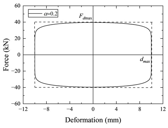
Figure 3.
Hysteresis curve of the viscous damper without dynamic stiffness.
It is obvious that the error is only related to the damping exponent of the viscous damper. Figure 4 shows that the ratio varies with in the range of 0 to 1. The fitting expression of the reduction coefficient of the parallelogram is given as follows:
Through , the energy dissipation of the damper can be estimated, which is shown as:
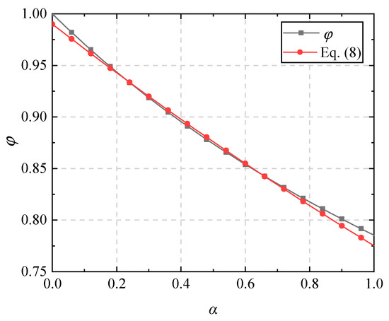
Figure 4.
Difference between and Equation (8).
Next, when the dynamic stiffness is considered, no longer equals . The calculation of is same as Equation (5), but in Equation (5) is difficult to obtain. can be approximately obtained by:
where is the deformation of the Maxwell model at zero force, which equals the maximum deformation of the damping element, namely . In general, obtaining is complicated; however, we can obtain the maximum deformation of the Maxwell model easily through analysis. In this light, the relation between and can be explored. This relationship depends on the damping exponent , the dynamic stiffness , the circular frequency of the structure, and the maximum deformation of the Maxwell model . The first three parameters are decided by the type of viscous damper and the structural characteristics. Therefore, varies with . The JSSI Manual provides a fitting expression with high accuracy [32]. Before the expression is given, the pseudo loss of stiffness of the viscous damper is defined:
where represents the loss of the stiffness of the viscous damper.
The ratio of the loss of stiffness to the dynamic stiffness is:
and the ratio of to is given as follows [32]:
where represents the ratio of to . The applicable condition of Equation (13) is , which can fully cover the common range of the parameters of the viscous dampers in practical design. Therefore, Equation (10) can be written as:
The strain energy of the viscous damper can be calculated as half of the product of the maximum damping force and the maximum deformation in one cycle. Consistent with the definition of Equation (4), the EDR of viscous damper can be approximately calculated as follows:
It can be found that can be determined by and . As varies with and is decided by the given , is the function of . Therefore, can reflect the energy dissipation capacity of the viscous damper, and the dampers will be more effective when configured at locations with large story drift. In addition, the limit of story drifts of the damped structure is determined according to the target structural performance. Hence, as the structural performance is determined, the UDR of dampers can be estimated, which will be discussed in a later section.
2.2. Basic Concept of Equivalent Damping Ratio for Viscously Damped Structure
Pushover analysis is a common method to evaluate structural seismic performance. According to performance-based seismic design, several pushover methods have been proposed [49,50]. In this study, the CSM was adopted.
As a kind of nonlinear analysis method, the nonlinear behaviors of the structural members should be taken into consideration. When the earthquake drives the structure into an inelastic range, the additional structural damping, which is mainly evoked by the hysteretic effect of the structure members, will be generated. The structural hysteretic damping can also be evaluated by structural EDR, which is a function of the structural ductility factor [51]:
where is the damping ratio of the primary structure and is the inherent damping ratio of the structure.
When it affects the energy dissipation structure, the damping induced by the dampers should also be considered. The EDR of the damped structure can be written as:
where is the additional EDR induced by the dampers.
In the CSM, a spectral reduction factor is utilized to decrease the elastic spectrum to a reduced response spectrum. The performance point is the intersection point of the reduced response spectrum and the structural capacity spectrum. As the EDR of the damped structure is obtained, the reduction factor is given by [50]:
where is the spectral reduction value in a constant acceleration range of the spectrum and is spectral reduction value in a constant velocity range of spectrum. The reduced response spectrum is illustrated in Figure 5; is the natural period of the primary structure and is the characteristic period of the site soil.
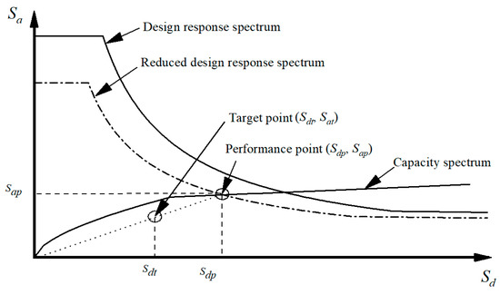
Figure 5.
Illustration of performance point and the target point.
2.3. Target Response Mitigation Ratio (RMR)
Since the performance point can be obtained through CSM, the inter-story drift, , hereafter referred as drift, can be obtained at this point. Based on the concept of performance-based seismic design, the limits of the drift are assigned according to different performance levels.
For the structures with additional dampers, the primary structure is supposed to be elastic under frequent earthquakes and exempt from collapse under rare earthquakes. A proper limit for the drift in the design stage should be chosen with respect to the design requirements. The target RMR can be determined based on the drift limit , which is shown as follows:
The story drifts at the performance point can also be utilized to determine the location of dampers. For all kinds of dampers, it is more effective to install them on stories with large drifts, because that indicates that the story is relatively weak and needs strengthening. Furthermore, minimum deformation is necessary for a viscous damper to dissipate input energy, and with a larger deformation, the dampers can dissipate more input energy. The stories that satisfy the condition of Equation (20) are appropriate for the installation of dampers:
where denotes the average of story drifts and denotes the limit value of the ratio of story drift to average drift. The value of should be set with consideration of the required story drift, the performance of the dampers, etc.
2.4. Determination of UDR
As discussed in Section 2.1, depends on . By obtaining the average for the installed dampers, the UDR of the dampers can be realized, which suggests that all dampers can offer uniform viscous damping under seismic excitations. Given that the required structural performance has been determined, the average should be calculated according to limit value of the drift .
The equivalent SDOF system of the structure is adopted. The diagram of the SDOF system with a viscous damper is depicted in Figure 6, in which the damper is represented by a Maxwell model. The equivalent story height of the SDOF system can be calculated by Equation (21):
where denotes the equivalent story height of the SDOF system, which is the mass-weighted average of story height, denotes the mass at level i, denotes the height between level i and level i-1, and is the total number of stories.
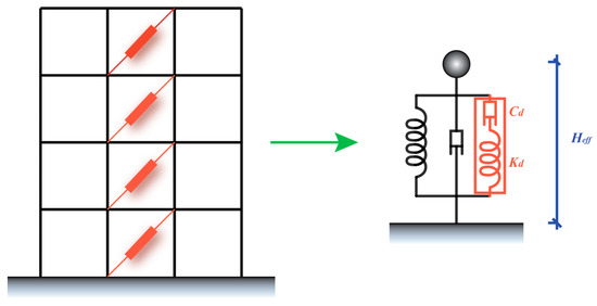
Figure 6.
Equivalent SDOF system of the structure.
The displacement can be obtained according to the limit of the drift by Equation (22):
In the SDOF system, the maximum deformation of the damper equals the displacement of the system, namely . of the viscous damper can be determined on the basis of the limit value of drift , the natural circular frequency of the structure , the dynamic stiffness coefficient , and the damping exponent of the damper . Then the uniform EDR of dampers , namely the UDR, can be determined through Equation (15).
2.5. Distribution of Damping Force
Given that has been determined, the target spectral displacement can be acquired from Equation (23):
where is the spectral displacement at the performance point, is the target spectral acceleration, is the spectral acceleration at the performance point, and is the EDR of the damped structure at the target spectral displacement.
Equation (23) implies that the equivalent period of the structure stays the same after the installation of viscous dampers, and the target spectral displacement is shown in Figure 5. The equivalent period can be obtained by:
Then the target additional EDR offered by dampers can be derived by:
where is the structural ductility factor at target spectral displacement.
According to the definition of EDR, the additional EDR induced by dampers can be calculated through Equation (26):
where is the energy consumed by the viscous dampers at level i, is the maximum strain energy of structure at level i, and is the maximum strain energy of dampers at level i.
By rational design and bracing of the viscous damper, the deformation of viscous damper at level i in the horizontal direction can be approximately equal to the inter-story displacement of the structure between level i and level i-1:
where is the inter-story displacement between level i and level i-1.
As the purpose of adding a viscous damper is to improve the original structural performance, and the structural performance is reflected by story drifts, the allocation of viscous dampers should be optimized with the story drifts. Based on this principle, the design damping forces of viscous dampers on the stories with large drifts can be increased, while the damping forces of viscous dampers on the stories with small drifts can be decreased. The damping force of a viscous damper at level i, , is expressed as:
where is the damping force factor of the viscous dampers.
Equation (29) can be obtained by substituting Equations (27) and (28) into Equation (26):
where is the story shear at level i. Transforming Equation (29), can be solved by:
As the damping force factor is known, the damping force of the viscous damper on each story can be obtained through Equation (28). According to , the damping coefficient and damping exponent of dampers can be determined.
3. Uniform Damping Ratio-Oriented Design Procedure
The design flow chart is depicted in Figure 7. The detailed design procedure based on the UDR concept is shown as follows:
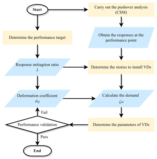
Figure 7.
Design flow chart based on the UDR concept.
According to the design demand, the parameters of the seismic response spectrum can be determined. By the adoption of CSM, in which the nonlinear behavior of members is considered, the original structural performance can be evaluated.
Corresponding to the performance point obtained by means of CSM, the structural seismic responses can be retrieved, i.e., story drift , story shear , and inter-story displacement . Then, the RMR can be calculated according to the target and original structural performance. Considering the utilization efficiency of energy dissipation of viscous dampers, the stories for damper installation can be determined by a reasonable . Therefore, based on the calculated , the additional EDR induced by the viscous damper is established.
The UDR of the viscous damper is determined according to the required seismic performance level. The key parameter, uniform EDR of the viscous damper, namely UDR, can be estimated by the limit value of drift , the natural circular frequency of the system , the dynamic stiffness coefficient , and the damping exponent of the damper . As UDR , structural responses, and supplemental EDR are known, the damping force factor can be solved through Equation (29). After that, the damping force at each story is calculated through Equation (28).
The proper viscous damper is selected in accordance with the damping force at each story. The damping coefficient and damping exponent of dampers can be determined. The viscous dampers should be installed at the locations in which the dampers can be fully utilized and prevent torsion effects.
4. Illustration Design and Discussions
4.1. Model Illustration
A benchmark six-story RC frame model was adopted to illustrate the design procedure based on the UDR concept. The plan and elevation of the facility are shown in Figure 8. The characteristic period of the site was 0.4 s. According to the Chinese Code of Seismic Design [52], the normalized demand seismic response spectrum is as follows:

Figure 8.
Plan and elevation of the RC frame: (a) plan; (b) elevation of frame in axis X3.
The story height and mass are shown in Table 2. The cross sections of the members are listed in Table 3. The members are made of concrete with a compression strength of 30 MPa according to the Code for Design of Concrete Structures [52]. The strength of the longitudinal and stirrup rebars was 345 MPa. The model of the structure was established using the software SAP2000 [53]. The beams and columns were modeled as elastic bars with two inelastic hinges at both ends. The moment hinge was applied for the beams, while the P-M-M hinge was applied for the columns. The moment–rotation relationship was obtained with the sTakeda model [54]. The thin shell element was utilized to simulate the floors and roof, and the assumption of rigid diaphragms for the floors was adopted. The distribution loads were exerted on the floors. The dead load was for every story. The live load was for stories 1–5 and for story 6. The self-weights of the floors were included in the dead load. The story mass was calculated by . The inherent damping ratio of the structure was 0.05 and the natural period of the structure was 1.266 s.
Table 2.
Story height and mass.
Table 3.
Cross section of members.
The stiffness of the structure in the Y direction was weak, so viscous dampers were required to be installed in this direction. For simplicity, only the seismic responses in the Y direction were analyzed.
4.2. Detailed Design Procedure
The pushover analysis was carried out on the primary structure and the force–displacement curve of the structure was recorded. After that, the force–displacement curve and the design response spectrum were transferred to an acceleration–displacement response spectrum.
The limit values of story drifts under the frequent, moderate, and rare earthquake scenarios adopted in this example are listed in Table 4. The performance point of the structure was obtained by CSM under a moderate seismic level. The responses of each story at the performance point were retrieved, which are plotted in Figure 9 and listed in Table 5. The limit value of story drifts was set to 0.33% and the value of RMR was 65.1%. In this case, the value of was set to 0.5, which indicated that all stories required the installation of viscous dampers.
Table 4.
Limit value of story drifts under different seismic levels.
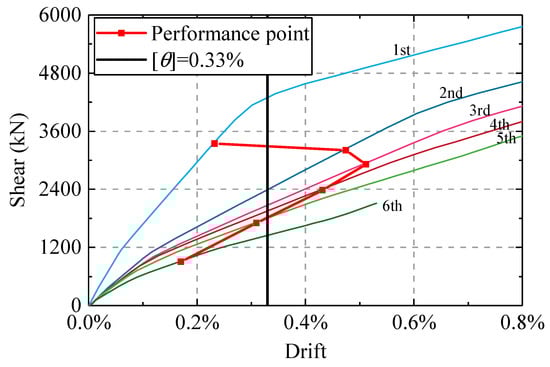
Figure 9.
curve for each story.
Table 5.
Structural responses at performance point.
According to , the target point of the structure was determined. The equivalent period at the target point was 1.5 s. Table 6 lists all the calculation parameters that are needed for Equation (25).
Table 6.
Calculation parameters.
Next, the deformation coefficient of the dampers was calculated. By means of modal analysis, the natural circular frequency of the structure was found to be . In this project, the damping exponent and the dynamic stiffness coefficient of the dampers were set to be 0.2 and , respectively. Because the limit value of drift , the natural circular frequency of the structure, the damping exponent and the dynamic stiffness coefficient were known, could be determined through (13), which was 0.884. Therefore, the UDR of viscous damper was 0.53.
The damping force factor was derived by substituting and story responses and into Equation (29). As a result, was determined to be 1135 kN. Therefore, the damping force of the dampers at each story was determined. The damping coefficient of the viscous damper at each story an be calculated according to Equation (32):
where is the relative velocity at level i. The velocity at each story was taken to be 100 mm/s based on engineering experience. Table 7 shows the design parameters of the viscous damper.
Table 7.
Design parameters of viscous damper.
On each story, two viscous dampers were added along axis X3 and X9, respectively. The diagram of configurations along X3 is depicted in Figure 10. viscous dampers 1~6 represent the viscous dampers installed on the corresponding stories.
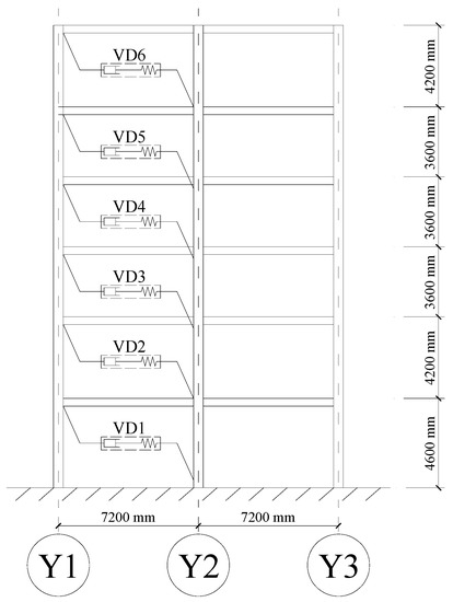
Figure 10.
Diagram of the viscous damper configuration in axis X3.
4.3. Seismic Performance Verification
A nonlinear time history analysis was carried out to validate the mitigation effect on the seismic response of the structure with the viscous dampers designed by the proposed method. The response of the damped structure (ST1) was compared with those of the structure without dampers (ST0). According to Chinese code [52], the site characteristic period for the soil is 0.4 s, and the acceleration response spectrum of the input seismic wave can be determined accordingly. Based on the spectrum, seven earthquake waves were selected, five of which were natural seismic records. These natural seismic records were selected from the Pacific Earthquake Engineering Research Center ground motion database [55]. The spectra of the selected waves were matched with the design acceleration spectrum. Detailed information of the natural seismic records is described in Table 8. The normalized spectra of all the waves are shown in Figure 11, in which AW1 and AW2 represent the two artificial records. Peak ground acceleration (PGA) was 0.7 m/s2, 2 m/s2, and 4 m/s2 corresponding to the frequent, moderate, and rare earthquake scenarios, respectively, according to the specifications in Chinese code [52].
Table 8.
Detailed information of the natural seismic records.
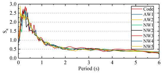
Figure 11.
Normalized spectra of seismic waves.
The story drifts of ST1 and ST0 were compared to illustrate the mitigation effects of the designed viscous dampers. Figure 12 and Figure 13 show a comparison of average story drifts and shears under frequent, moderate, and rare earthquakes. The story drifts were controlled within the limit values and the shears were simultaneously reduced.
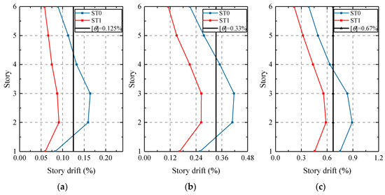
Figure 12.
Average story drifts of ST0 and ST1: (a) drifts under frequent earthquakes; (b) drifts under moderate earthquakes; (c) drifts under rare earthquake.
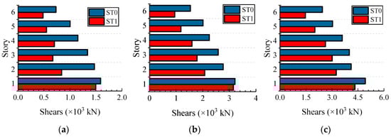
Figure 13.
Average story shears of ST0 and ST1: (a) Shears under frequently earthquake; (b) Shears under moderate earthquake; (c) Shears under rarely earthquake.
Viscous dampers can dissipate great input energy under different earthquake scenarios. The hysteresis curves of viscous dampers installed on the first, third, and fifth stories under AW1 for PGA = 200 gal are displayed in Figure 14, which indicates that the capacity of energy dissipation of the dampers was fully utilized. It should be noted that in practical design, the parameters of viscous dampers need not be strictly identical to the design values. Generally, for the purpose of convenience and efficiency, different viscous dampers with similar parameters are merged into one type.
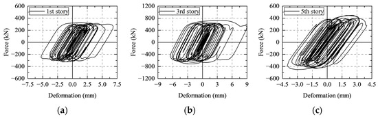
Figure 14.
Hysteresis of viscous damper under AW1 for PGA = 200 gal: (a) first story; (b) third story; (c) fifth story.
Table 9 shows the average EDR of dampers of ST1 under different seismic excitations. Because the story drift is well controlled within the limit value of story drift , the average value of under the earthquakes with PGA = 200 gal is close to and slightly less than the anticipated UDR 0.53. In addition, it can be observed that under different earthquakes with the same PGA are close to each other, which verifies the rationality of the UDR concept in a different way.
Table 9.
Average EDR of dampers in ST1.
4.4. Comparison with Classic Design Method and Discussion
To illustrate the advantages of the design method based on the UDR concept, it was compared to the classic method in the JSSI Manual [32]. The JSSI method adopts the elastic response spectrum, and the parameters of viscous dampers are determined according to lateral stiffness at each story.
The limit values of story drifts under different seismic levels for the JSSI design method were set to be the same as those for the UDR design method. The expected damping force and the damping coefficient of the viscous damper at each story obtained by the JSSI method are shown in Table 10.
Table 10.
Parameters of the viscous damper designed by the JSSI method.
The seismic responses of the structure designed by the JSSI method under the same earthquake waves were compared with those of the structure designed by the UDR method. Figure 15 represents a comparison of story drifts under frequent, moderate, and rare earthquakes, respectively. From Figure 15, it can be observed that the seismic responses of the two damped structures designed by the two different methods are similar.
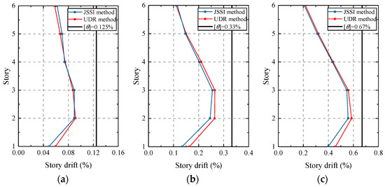
Figure 15.
Comparison of story drifts: (a) drifts under frequent earthquakes; (b) drifts under moderate earthquakes; (c) drifts under rare earthquakes.
Figure 16 shows the comparison of hysteresis curves of viscous dampers installed on the first story of the two damped structures under AW1 with PGA = 200 gal and NW3 with PGA = 400 gal. By reducing the damping force of the viscous dampers installed on the first story, the dampers of the structure designed by the UDR method obtain larger deformation, and the energy dissipation capacity of these dampers is more efficiently utilized. Moreover, the redundant damping forces of the dampers in the damped structure designed by the JSSI method can increase the forces in the members of the primary structure and lower the utilization efficiency of the energy dissipation capacity of the dampers.
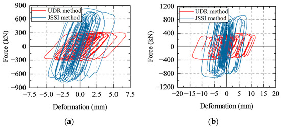
Figure 16.
Comparison of hysteresis curves of viscous damper: (a) hysteresis curves under AW1 with PGA = 200 gal; (b) hysteresis curves under NW3 with PGA = 400 gal.
The damping coefficient relates to the maximum damping force of the dampers, and the comparison of designed by the two methods is listed in Table 11. The sum of values of designed by the UDR method is 22% less than that of designed by the JSSI method, which indicates that the design based on the UDR concept is more economical and practical. The comparison further verifies the effectiveness, rationality, and economy of the design method based on the UDR concept.
Table 11.
Comparison of from the two methods.
5. Conclusions
This study introduced the UDR concept into the design of viscous dampers and formulated a UDR-oriented retrofitting design with rapid and simplified design formulae for viscous dampers that can consider the elastic–plastic performance of structures. The proposed design approach is constructed by deriving the detailed expressions of the EDR for viscous damper and damped structure , the determination of , the UDR of viscous dampers, and the calculation of . To demonstrate this method, a benchmark six-story RC frame structure was used, and the results of this study can be summarized as follows:
- The design method based on the UDR concept ensures the effective utilization of the energy dissipation capacity of the dampers, as the UDR of the dampers was judiciously determined according to the desired performance goals.
- The effectiveness, cost-effectiveness, and practicality of the configuration of viscous dampers based on the UDR design method was confirmed through a comparative study with the JSSI method.
- When calculating the energy dissipation of viscous dampers, the simplified parallelogram method is not only a reliable approximation in engineering practice but also convenient for calculations.
Author Contributions
Conceptualization, X.H. and Z.Z.; methodology, X.H. and Z.Z.; software, X.H. and Z.Z.; validation, X.H., Z.Z. and R.Z.; formal analysis, X.H.; investigation, X.H., Z.Z. and R.Z.; writing—original draft preparation, X.H. and Z.Z.; writing—review and editing, X.H., Z.L., M.G., L.G. and Z.Z.; visualization, X.H., Z.Z., Z.L., M.G., L.G. and R.Z.; supervision, R.Z.; project administration, R.Z.; funding acquisition, R.Z. All authors have read and agreed to the published version of the manuscript.
Funding
This study was supported by the Scientific Research Fund of Institute of Engineering Mechanics, China Earthquake Administration [Grant No. 2020EEEVL0401], the Basic Research Project of the State Key Laboratory of the Ministry of Science and Technology [Grant No. SLDRCE19A-02], the Research Open Funds for the Shandong Key Laboratory of Civil Engineering Disaster Prevention and Mitigation [Grant No. CDPM2021KF14], and the Shanghai Institute of Technology [Grant No. YJ2021-91]. All support is gratefully acknowledged.
Data Availability Statement
The datasets are available from the corresponding author on reasonable request.
Conflicts of Interest
The authors declare no conflict of interest.
References
- Basu, B.; Bursi, O.S.; Casciati, F.; Casciati, S.; Grosso, A.E.D.; Domaneschi, M.; Faravelli, L.; Holnicki-Szulc, J.; Irschik, H.; Krommer, M.; et al. A European Association for the Control of Structures joint perspective. Recent studies in civil structural control across Europe. Struct. Control. Health Monit. 2014, 21, 1414–1436. [Google Scholar] [CrossRef]
- Ghaedi, K.; Ibrahim, Z.; Adeli, H.; Javanmardi, A. Invited review: Recent developments in vibration control of building and bridge structures. J. Vibroeng. 2017, 19, 3564–3580. [Google Scholar] [CrossRef]
- Zucca, M.; Longarini, N.; Simoncelli, M.; Aly, A.M. Tuned Mass Damper Design for Slender Masonry Structures: A Framework for Linear and Nonlinear Analysis. Appl. Sci. 2021, 11, 3425. [Google Scholar] [CrossRef]
- Zhao, Z.; Wang, Y.; Hu, X.; Weng, D. Seismic performance upgrading of containment structures using a negative-stiffness amplification system. Eng. Struct. 2022, 262, 114394. [Google Scholar] [CrossRef]
- Hu, X.; Zhao, Z.; Yang, K.; Weng, D.; Hu, D. Design theory of dual-isolated tuned liquid damper for vibration control of high-rise buildings. J. Build. Struct. 2022, 43, 205. [Google Scholar]
- Zhao, Z.; Chen, Q.; Hu, X.; Zhang, R. Enhanced energy dissipation benefit of negative stiffness amplifying dampers. Int. J. Mech. Sci. 2023, 240, 107934. [Google Scholar] [CrossRef]
- Mazza, F.; Vulcano, A. Nonlinear Response of RC Framed Buildings with Isolation and Supplemental Damping at the Base Subjected to Near-Fault Earthquakes. J. Earthq. Eng. 2009, 13, 690–715. [Google Scholar] [CrossRef]
- Hao, L.F.; Zhang, R.F. Structural safety redundancy-based design method for structure with viscous dampers. Struct. Eng. Mech. 2016, 59, 821–840. [Google Scholar] [CrossRef]
- Shen, H.; Zhang, R.F.; Weng, D.G.; Gao, C.; Luo, H.; Pan, C. Simple design method of structure with metallic yielding dampers based on elastic-plastic response reduction curve. Eng. Struct. 2017, 150, 98–114. [Google Scholar] [CrossRef]
- Hao, L.F.; Zhang, R.F.; Jin, K. Direct design method based on seismic capacity redundancy for structures with metal yielding dampers. Earthq. Eng. Struct. Dyn. 2018, 47, 515–534. [Google Scholar] [CrossRef]
- Pan, C.; Zhang, R. Design of structure with inerter system based on stochastic response mitigation ratio. Struct. Control. Health Monit. 2018, 25, e2169. [Google Scholar] [CrossRef]
- Zhang, R.; Wang, C.; Pan, C.; Shen, H.; Ge, Q.; Zhang, L. Simplified design of elastoplastic structures with metallic yielding dampers based on the concept of uniform damping ratio. Eng. Struct. 2018, 176, 734–745. [Google Scholar] [CrossRef]
- Longarini, N.; Zucca, M. A chimney’s seismic assessment by a tuned mass damper. Eng. Struct. 2014, 79, 290–296. [Google Scholar] [CrossRef]
- Gluck, N.; Reinhorn, A.M.; Gluck, J.; Levy, R. Design of supplemental dampers for control of structures. J. Struct. Eng. 1996, 122, 1394–1399. [Google Scholar] [CrossRef]
- Takewaki, I. Optimal damper placement for planar building frames using transfer functions. Struct. Multidiscip. Optim. 2000, 20, 280–287. [Google Scholar] [CrossRef]
- Singh, M.P.; Moreschi, L.M. Optimal placement of dampers for passive response control. Earthq. Eng. Struct. Dyn. 2002, 31, 955–976. [Google Scholar] [CrossRef]
- Dargush, G.F.; Sant, R.S. Evolutionary aseismic design and retrofit of structures with passive energy dissipation. Earthq. Eng. Struct. Dyn. 2005, 34, 1601–1626. [Google Scholar] [CrossRef]
- Aydin, E.; Boduroglu, M.H.; Guney, D. Optimal damper distribution for seismic rehabilitation of planar building structures. Eng. Struct. 2007, 29, 176–185. [Google Scholar] [CrossRef]
- Leu, L.J.; Chang, J.T. Optimal Allocation of Non-Linear Viscous Dampers for Three-Dimensional Building Structures. Procedia Eng. 2011, 14, 2489–2497. [Google Scholar] [CrossRef]
- Martinez, C.A.; Curadelli, O.; Compagnoni, M.E. Optimal placement of nonlinear hysteretic dampers on planar structures under seismic excitation. Eng. Struct. 2014, 65, 89–98. [Google Scholar] [CrossRef]
- Raju, K.R.; Ansu, M.; Iyer, N.R. A methodology of design for seismic performance enhancement of buildings using viscous fluid dampers. Struct. Control. Health Monit. 2014, 21, 342–355. [Google Scholar] [CrossRef]
- Shin, H.; Singh, M.P. Minimum failure cost-based energy dissipation system designs for buildings in three seismic regions—Part II: Application to viscous dampers. Eng. Struct. 2014, 74, 275–282. [Google Scholar] [CrossRef]
- Alibrandi, U.; Falsone, G. Optimal design of dampers in seismic excited structures by the Expected value of the stochastic Dissipated Power. Probab. Eng. Eng. Mech. 2015, 41, 129–138. [Google Scholar] [CrossRef]
- Lavan, O. Optimal Design of Viscous Dampers and Their Supporting Members for the Seismic Retrofitting of 3D Irregular Frame Structures. J. Struct. Eng. 2015, 141, 15. [Google Scholar] [CrossRef]
- Losanno, D.; Spizzuoco, M.; Serino, G. An optimal design procedure for a simple frame equipped with elastic-deformable dissipative braces. Eng. Struct. 2015, 101, 677–697. [Google Scholar] [CrossRef]
- Huang, X.M. Evaluation of genetic algorithms for the optimum distribution of viscous dampers in steel frames under strong earthquakes. Earthq. Struct. 2018, 14, 215–227. [Google Scholar] [CrossRef]
- Lavan, O. A methodology for the integrated seismic design of nonlinear buildings with supplemental damping. Struct. Control. Health Monit. 2015, 22, 484–499. [Google Scholar] [CrossRef]
- Zhou, X.Y.; Yu, R.F.; Dong, D. Complex mode superposition algorithm for seismic responses of non-classically damped linear MDOF system. J. Earthq. Eng. 2004, 8, 597–641. [Google Scholar] [CrossRef]
- Zare, A.R.; Ahmadizadeh, M. Design of viscous fluid passive structural control systems using pole assignment algorithm. Struct. Control. Health Monit. 2014, 21, 1084–1099. [Google Scholar] [CrossRef]
- Greco, R.; Marano, G.C. Optimum design of viscous dissipative links in wall-frame systems. Struct. Des. Tall Spec. Build. 2016, 25, 412–428. [Google Scholar] [CrossRef]
- Halperin, I.; Ribakov, Y.; Agranovich, G. Optimal viscous dampers gains for structures subjected to earthquakes. Struct. Control. Health Monit. 2016, 23, 458–469. [Google Scholar] [CrossRef]
- JSSI Manual. In Design and Construction Manual for Passively Controlled Buildings, 2nd ed.; Japan Society of Seismic Isolation: Tokyo, Japan, 2007.
- Kim, J.; Choi, H.; Min, K.W. Performance-based design of added viscous dampers using capacity spectrum method. J. Earthq. Eng. 2003, 7, 1–24. [Google Scholar] [CrossRef]
- Uetani, K.; Tsuji, M.; Takewaki, I. Application of an optimum design method to practical building frames with viscous dampers and hysteretic dampers. Eng. Struct. 2003, 25, 579–592. [Google Scholar] [CrossRef]
- Silvestri, S.; Gasparini, G.; Trombetti, T. A Five-Step Procedure for the Dimensioning of Viscous Dampers to Be Inserted in Building Structures. J. Earthq. Eng. 2010, 14, 417–447. [Google Scholar] [CrossRef]
- Palermo, M.; Silvestri, S.; Landi, L.; Gasparini, G.; Trombetti, T. Peak velocities estimation for a direct five-step design procedure of inter-storey viscous dampers. Bull. Earthq. Eng. 2016, 14, 599–619. [Google Scholar] [CrossRef]
- Landi, L.; Fabbri, O.; Diotallevi, P.P. A two-step direct method for estimating the seismic response of nonlinear structures equipped with nonlinear viscous dampers. Earthq. Eng. Struct. Dyn. 2014, 43, 1641–1659. [Google Scholar] [CrossRef]
- Landi, L.; Lucchi, S.; Diotallevi, P.P. A procedure for the direct determination of the required supplemental damping for the seismic retrofit with viscous dampers. Eng. Struct. 2014, 71, 137–149. [Google Scholar] [CrossRef]
- Landi, L.; Conti, F.; Diotallevi, P.P. Effectiveness of different distributions of viscous damping coefficients for the seismic retrofit of regular and irregular RC frames. Eng. Struct. 2015, 100, 79–93. [Google Scholar] [CrossRef]
- Anh, N.D.; Nguyen, N. Design of non-traditional dynamic vibration absorber for damped linear structures. Proc. Inst. Mech. Eng. Part C-J. Eng. Mech. Eng. Sci. 2014, 228, 45–55. [Google Scholar] [CrossRef]
- Attary, N.; Symans, M.; Nagarajaiah, S.; Reinhorn, A.M.; Constantinou, M.C.; Sarlis, A.A.; Pasala, D.T.R.; Taylor, D. Numerical simulations of a highway bridge structure employing passive negative stiffness device for seismic protection. Earthq. Eng. Struct. Dyn. 2015, 44, 973–995. [Google Scholar] [CrossRef]
- Hu, X.Y.; Chen, Q.J.; Weng, D.G.; Zhang, R.F.; Ren, X.S. Estimation of additional equivalent damping ratio of the damped structure based on energy dissipation. Adv. Civ. Eng. 2019, 2019, 8052413. [Google Scholar] [CrossRef]
- Dong, B.P.; Sause, R.; Ricles, J.M. Seismic Response and Performance of a Steel MRF Building with Nonlinear Viscous Dampers under DBE and MCE. J. Struct. Eng. 2016, 142, 16. [Google Scholar] [CrossRef]
- Guo, J.W.W.; Christopoulos, C. Performance spectra based method for the seismic design of structures equipped with passive supplemental damping systems. Earthq. Eng. Struct. Dyn. 2013, 42, 935–952. [Google Scholar] [CrossRef]
- Chopra, A.K.; Naeim, F. Dynamics of Structures: Theory and Applications to Earthquake Engineering, 4th ed.; Prentice Hall: Upper Saddle River, NJ, USA, 2012; Volume 17. [Google Scholar]
- Christensen, R.M. Chapter I—Viscoelastic Stress Strain Constitutive Relations. In Theory of Viscoelasticity, 2nd ed.; Academic Press: New York, NY, USA, 1982; pp. 1–34. [Google Scholar] [CrossRef]
- Clough, R.W.; Penzien, J. Dynamics of Structures, 3rd ed.; Computers & Structures, Inc.: Berkeley, CA, USA, 2003. [Google Scholar]
- Soong, T.T.; Constantinou, M.C. Passive and Active Structural Vibration Control in Civil Engineering; Springer: Wien, Austria; New York, NY, USA, 1994. [Google Scholar]
- FEMA356; Prestandard and Commentary for the Seismic Rehabilitation of Buildings: Rehabilitation Requirements. Chapter 9–30; American Society of Civil Engineers: Washington, DC, USA, 2000.
- ATC40; Seismic Evaluation and Retrofit of Concrete Building. Applied Technology Council: Redwood City, CA, USA, 1996; Volume ATC–40.
- Gulkan, P.; Sozen, M.A. Inelastic Responses of Reinforced Concrete Structures to Earthquake Motions. Ournal Proc. 1977, 71, 109–115. [Google Scholar]
- GB50011-2010; Chinese Code for Seismic Design of Buildings. China Architecture & Building Press: Beijing, China, 2010.
- Wilson, E.L. SAP2000: Integrated Finite Element Analysis Design of Structures; Computers and Structures: Berkeley, CA, USA, 1997. [Google Scholar]
- Takeda, T. Reinforced Concrete response to simulated earthquakes. J. Struct. Div. Proc. Am. Soc. Civ. Eng. 1970, 96, 2557–2573. [Google Scholar] [CrossRef]
- Darragh, B.; Silva, W.; Gregor, N. Strong motion record processing procedures for the PEER center. In Proceedings of the COSMOS Workshop on Strong-Motion Record Processing, Richmond, CA, USA, 26–27 May 2004; pp. 1–12. [Google Scholar]


Disclaimer/Publisher’s Note: The statements, opinions and data contained in all publications are solely those of the individual author(s) and contributor(s) and not of MDPI and/or the editor(s). MDPI and/or the editor(s) disclaim responsibility for any injury to people or property resulting from any ideas, methods, instructions or products referred to in the content. |
© 2023 by the authors. Licensee MDPI, Basel, Switzerland. This article is an open access article distributed under the terms and conditions of the Creative Commons Attribution (CC BY) license (https://creativecommons.org/licenses/by/4.0/).