Article

Influence of Excavation Radius on Behavior of Circular Foundation Pits Supported by Prefabricated Recyclable Structures: Full-Scale Experimental and Numerical Analysis

1
School of Civil Engineering, Sun Yat-sen University, Zhuhai 519082, China
2
Southern Marine Science and Engineering Guangdong Laboratory, Zhuhai 519000, China
3
Guangdong Research Center for Underground Space Exploitation Technology, Guangzhou 510275, China
4
Best Dr Infrastructure Hospital, Zhumadian 463000, China
5
Guangzhou Municipal Construction Group Co., Ltd., Guangzhou 510275, China
6
School of Water Conservancy and Transportation, Zhengzhou University, Zhengzhou 450001, China
*
Authors to whom correspondence should be addressed.
Buildings 2024, 14(10), 3110; https://doi.org/10.3390/buildings14103110 (registering DOI)
Submission received: 23 August 2024 / Revised: 19 September 2024 / Accepted: 26 September 2024 / Published: 27 September 2024

Abstract

:
A foundation pit’s excavation area, which is determined by its radius in a circular foundation pit, exerts a considerable influence on the pit’s behavior. Using a full-scale experiment on a circular foundation pit retained by a prefabricated recyclable supporting structure (PRSS), this study develops a series of axisymmetric numerical models to systematically investigate the influence of excavation radius on the pit’s deformation, stress, and stability. Furthermore, simulation results from axisymmetric models are compared with those from plane strain models to illustrate the influence mechanism. The results show that at a given excavation depth, the deflection and bending moments of the supporting piles, the earth pressure on the non-excavation side, and ground surface settlement increase with the enlarged excavation radius, but the increase rate progressively decreases. However, the foundation pit’s safety factor decreases with an increasing excavation radius and gradually stabilizes. When the excavation radius exceeds 50 m, its influence on the foundation pit’s behavior significantly diminishes. The axisymmetric model results closely approximate those from the plane strain models, suggesting that the spatial arching effects of the circular foundation pit can be disregarded.

1. Introduction

The rapid urbanization of China has accelerated the expansion of underground infrastructure, resulting in a substantial rise in foundation pit projects. Consequently, foundation pits with varying excavation areas have become increasingly prevalent. The performance of a foundation pit is significantly influenced by the dimensions of its planar excavation area [1,2]. However, this influence is not considered in the current design methodologies for foundation pit supporting structures [3], resulting in a large deviation in observed forces and deformations compared with those calculated in designs [4]. Thus, analyzing the behavior of foundation pits with different excavation areas is essential for practical applications.
Field monitoring data indicate that, for similar excavation depths and geological conditions, the movements of retaining walls and the surrounding soil are more significant in foundation pits with larger excavation areas than in pits with smaller excavation areas [5,6,7,8]. In a rectangular foundation pit, the excavation width determines the excavation area, whereas for a circular foundation pit, the determining parameter is the excavation radius. Using 2D finite-element analysis, Mana and Clough [9] studied foundation pit deformation relative to excavation width. Based on a theoretical analysis, Wang [10] pointed out that a smaller excavation width results in a higher safety factor for the foundation pit. Based on several case studies of foundation pits with various excavation widths, Xiao et al. [11] and Park [12] claimed that increasing the excavation width initially increases both lateral wall deflection and ground settlement, though these values generally stabilize afterward. Furthermore, the impact of width on foundation pit performance appears to be largely independent of the retaining wall type. In a comparative analysis of monitoring data from several circular foundation pits, Tan and Wang [13] found that for foundation pits exceeding 30,000 m² in area, deformations are three to five times greater than those of typical small foundation pits with areas not exceeding 6,000 m². Additionally, the influence zone of large foundation pits extends much further than that of small foundation pits. Zeng et al. [14] indicated that the deformation in retaining walls and surrounding soil due to pre-excavation dewatering increases when the foundation pit widens. However, a critical foundation pit width exists, within which deformations escalate rapidly; beyond this critical width, the foundation pit’s behavior slightly varies. Huang et al. [15] concluded that at a given excavation depth, the passive zone’s capacity to reduce deformations caused by excavation decreases as the excavation width expands. This increases deformations in the retaining wall and the surrounding soil, though the increase rate gradually decreases.
Compared with the many studies on the influence of excavation width on the performance of rectangular foundation pits, there have been limited investigations of the impact of excavation radius on the performance of circular foundation pits. Nevertheless, some researchers have noted the behavior of circular foundation pits during construction and observed that deformations in these pits significantly differ from typical deformation patterns in retaining walls [16,17,18]. This is because the behavior of the soil surrounding circular foundation pits is influenced by the arching effect [19], wherein lateral earth pressures tangentially compress and radially extend. Earth pressure on retaining walls in circular foundation pits decreases with an increasing radius [20,21]. Moreover, for circular foundation pits, the diameter rather than the penetration ratio of the retaining wall plays a primary role in determining the pit’s behavior [22]. Most numerical simulations of circular foundation pit issues use 2D axisymmetric models [23,24,25,26,27]. Keshavarz and Ebrahimi [28] demonstrated that passive lateral earth pressure in axial symmetry yields greater results than those under plane strain conditions. The above research on the influence of excavation radius on circular foundation pits has primarily involved experimental or theoretical studies of soil pressure distribution or case studies on the performance of foundation pits with specific radii. There is a lack of research using numerical modeling methods to study the performance of circular foundation pits with different radii.
PRSS is a novel retaining system that consists of supporting piles, walings, steel plates, and resilient waterproofing polymers [29,30,31,32]. Due to its high construction efficiency, reusability, and excellent structural performance, it is widely used in circular foundation pits with varying excavation radii, such as working shafts, underground grain silos, and automated underground parking garages [33,34]. Therefore, it is necessary to study the influence of excavation radius on the behavior of circular foundation pits to deepen our understanding of those supported by PRSSs or other retaining wall types [35,36]. This study includes a full-scale experiment on a circular foundation pit supported by PRSSs. Subsequently, a series of 2D axisymmetric numerical models were developed based on this experiment, and field monitoring data were used for validation. The influence of excavation radius on the behavior of the circular foundation pit, including the deflection and bending moments of the supporting piles, earth pressure, ground surface settlement, and the safety factor, was systematically analyzed. In addition, simulation results from axisymmetric models are compared with those from plane strain models to illustrate this influence mechanism. Through a thorough investigation of these factors, this study significantly enhances our understanding of how excavation radius impacts the behavior of circular foundation pits supported by PRSSs or similar retaining systems.

2. Full-Scale Experimental Scheme

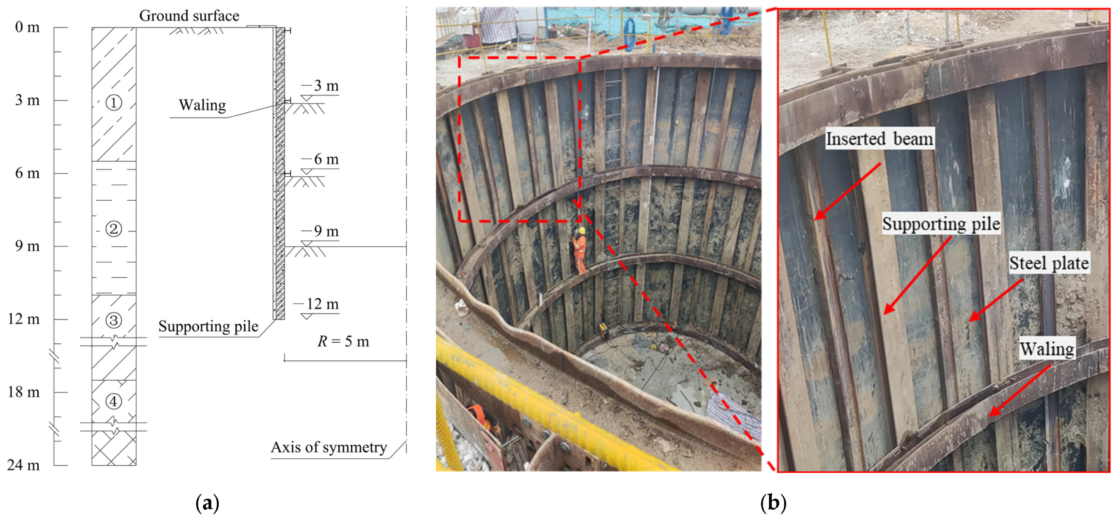
2.1. Site and Structure Description

The full-scale experiment took place in Pingyu County, Zhumadian, China. Figure 1 shows that the foundation pit is cylindrical, with a 5 m radius and a maximum depth of 9 m. The supporting piles are 12 m long, spaced 1.57 m apart [37]. Additionally, a waling is set up at each 3 m interval beneath the ground surface. Steel plates support the soil between the support piles, with dimensions of 12 m in length, 1.45 m in width, and 8 mm in thickness. To prevent excessive deformation in these plates, 12 m long beams are embedded in front of them.
A thorough geotechnical investigation revealed the presence of four soil layers within a depth range of 24 m, all classified as silty clay. These layers are designated as ①, ②, ③, and ④, and their fundamental properties are detailed in Table 1. In Table 1, the cone penetration resistance in the cone penetration test (CPT) and the blow counts of the standard penetration test (SPT) were obtained through field investigation, with other parameters obtained from laboratory testing of soil samples. Additionally, the groundwater table was 3.5 m beneath the surface.

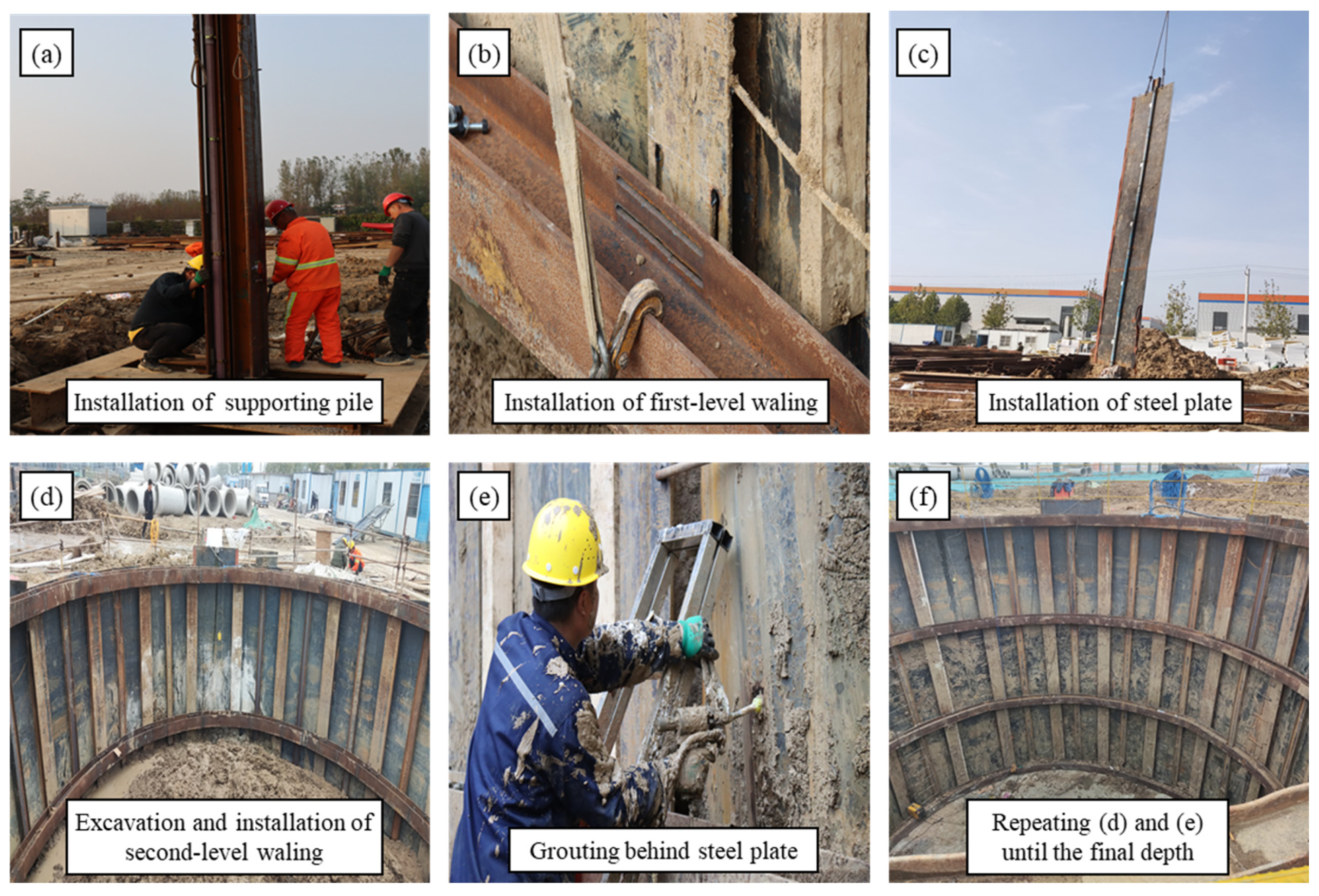
2.2. Construction Process

Figure 2 illustrates the construction process for a foundation pit supported by a PRSS. The process begins with installing supporting piles in bored holes. Next, a first-level waling is assembled to connect these supporting piles. Steel plates are then embedded in the soil. Subsequently, the groundwater level inside the foundation pit is lowered to −10 m below the ground surface through four dewatering wells. After excavating to the first design depth, a second-level waling is installed. To improve the PRSS’s impermeability, expanded polyurethane is used as a grouting material behind the steel plates. This polyurethane expands upon application, filling gaps and voids to create a more effective barrier against water infiltration, significantly enhancing the PRSS’s ability to prevent water from penetrating the structural components. The excavation, waling installation, and grouting cycle is repeated until the final depth is achieved. A more detailed PRSS construction procedure in practical engineering can be found in studies by Wang et al. [38] and Pan et al. [33].

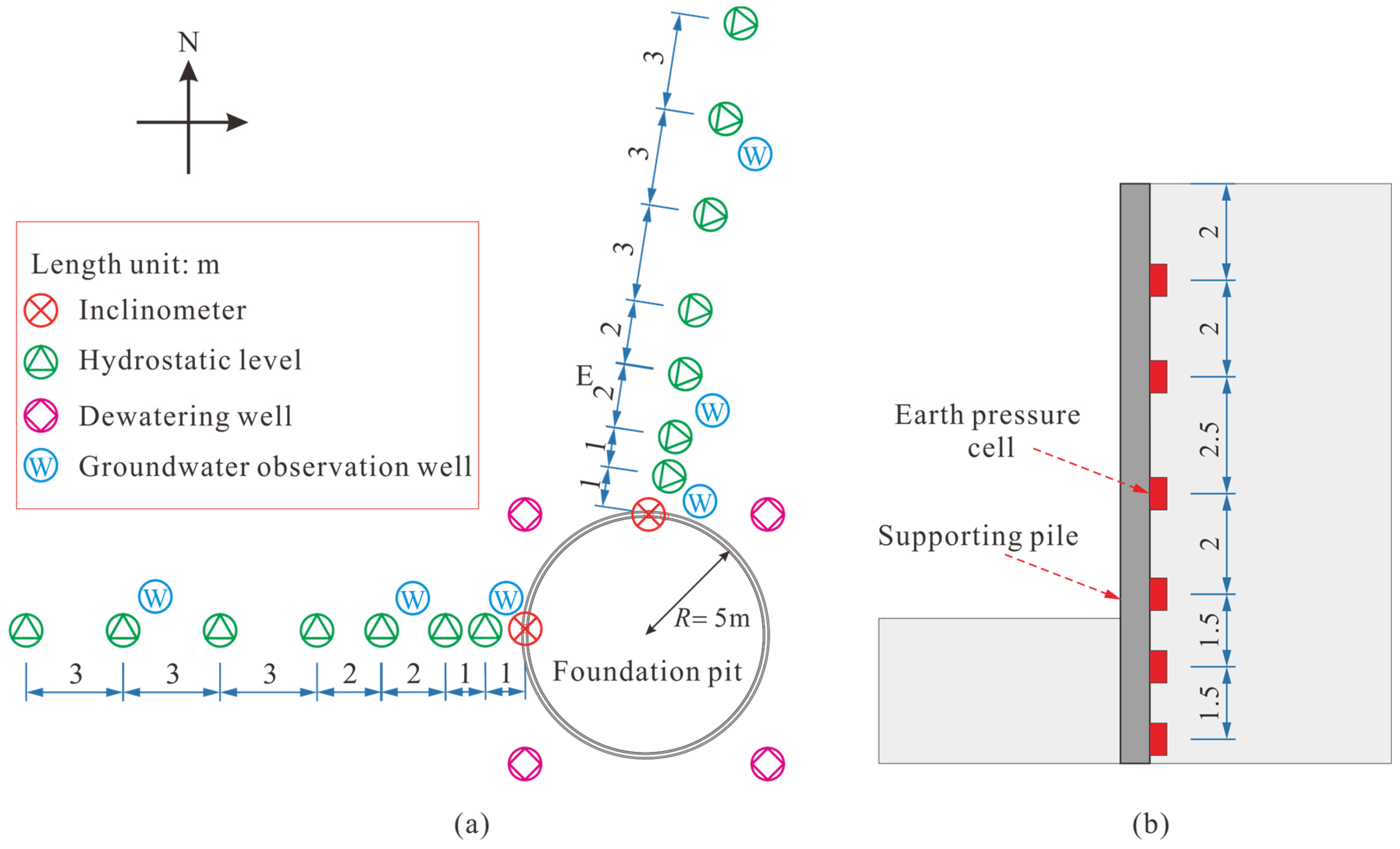
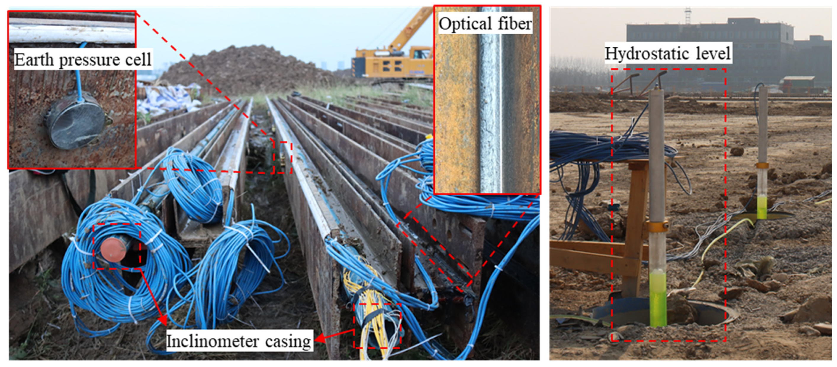
2.3. Instrumentation

To monitor the foundation pit’s behavior, various instruments were installed, as depicted in Figure 3 and Figure 4. Inclinometer casings were placed on the supporting piles to measure lateral displacement caused by excavation and dewatering processes. The DM601 inclinometer is utilized, offering an accuracy of ±2 mm per 25 m. Horizontal displacements at the top of the supporting piles were measured using a total station, which served as a reference point for correcting the deflection of the supporting piles. Earth pressure cells were positioned on the non-excavation side of the supporting piles to assess pressure changes. The type of the soil pressure cell is DMTY, with an accuracy of ≤0.5% FS. Prior to installation, the earth pressure cells undergo a calibration process, after which their initial value is recorded upon completion of the installation. Additionally, strain-sensing optical fibers were attached to the supporting piles to measure bending moments. The NZS-DSS-C06 strain-sensing optical fiber is utilized, which exhibits excellent coupling with the measured object through the use of adhesives, ensuring high strain transfer performance. Furthermore, the DM-JL hydrostatic levels were positioned at the ground surface outside the foundation pit to monitor ground surface settlement, with an accuracy of 0.001 mm. To minimize external disturbances, the instrument’s base is anchored in concrete at a depth of 0.5 m below the surface. Corrections for the measured settlement are performed using reference points located outside the excavation’s area of influence. Additionally, four dewatering wells were uniformly installed 1.5 m around the foundation pit to keep the working face dry during construction. Moreover, groundwater observation wells were installed outside the excavation to monitor groundwater level variations.

3. Numerical Simulation

3.1. Finite-Element Model and Boundary Conditions

Extensive analyses of the foundation pit were performed using the finite-element software Plaxis 2D, version 2023.2. A series of 2D axisymmetric models were established, as was a plane strain model. The basic axisymmetric and plane strain models are presented in Figure 5; Hp is the length of the supporting pile, which is equal to the sum of the excavation depth (He) and the embedment depth (Hd). The model dimensions used in the analysis are R + 5He in length and 2Hp in width, ensuring that the numerical results are not affected by the boundaries [39]. Horizontal movement constraints (roller support) are applied to the vertical boundaries of the models, while both horizontal and vertical movement constraints (pin support) are employed at the bottom of the models. The axis of symmetry in the symmetric model is along the left edge. The soil is represented by 15-noded triangular elements. The supporting structure consists of supporting piles, inserted beams, and steel plates, and it is equivalently modeled as a wall based on the principle of equal bending stiffness and simulated using plate elements. Interfaces are set up between the soil and supporting structure to simulate their interaction. The support effect from walings is simulated using a fixed-end anchor [40]. The soil mesh surrounding the PRSS is adjusted to enhance computational efficiency and accuracy. Near the foundation pit—where detailed analysis is crucial owing to the high complexity of interactions and potential stress concentrations—the mesh is refined to provide more precise modeling. Conversely, at greater distances from the pit, where the effects are less pronounced, the mesh is coarsened to reduce computational demands while maintaining sufficient model accuracy. An optimized mesh size is determined by comparing calculation results using different mesh densities, with further refinement showing negligible differences in the computations.

3.2. Material Constitutive Model and Parameters

The HSS model developed by Benz [41] has been extensively adopted in foundation pit analysis owing to its capacity to reflect the soil’s small strain behavior [2,42,43]. In this model, the small strain behavior of the soil is determined by two parameters: the reference shear modulus ( G 0 r e f ) at a given stress level and the shear strain ( γ 0.7 ) at which the shear modulus decreases to about 70% of G 0 r e f . The reference shear modulus is obtained from the relationship introduced by Hardin and Black [44]. The formula proposed by Benz [41] determines the threshold shear strain. Table 2 provides a detailed list of the soil parameters utilized for the HSS in this study. The relationship of the stiffness parameters ( E s : E o e d r e f : E 50 r e f : E u r r e f = 1 : 1 : 1 : 3 ) is used in this paper [45,46].
The interfaces adhere to the Mohr–Coulomb criterion, and their material properties are derived from the surrounding soil with a reduction factor (Rinter) [47]. In accordance with the friction coefficient between soil and steel recommended by Potyondy [48], the interaction parameter, Rinter, is uniformly assigned a value of 0.65 for each soil layer in the model.
The numerical analyses assume that the supporting structure and walings display linear elastic behavior. Table 3 offers comprehensive details on their properties and parameters, which were obtained from the specifications of “Hot-Rolled H Sections and Cut T Sections” [49]. Owing to the thin steel plates between the piles and their lack of fixed connection to the piles, the supporting structure composed of piles, inserted beams, and steel plates exhibits orthotropic elastic behavior, similar to a contiguous pile wall [50]. Therefore, the out-of-plane axis stiffness is neglected and set to zero.

3.3. Simulation Procedures

The foundation pit construction simulation was achieved in several steps, including activating and deactivating relevant element meshes and boundary conditions. In the initial stage, boundary conditions are activated to establish the initial stress field on-site. Subsequently, supporting structures and crown beams are installed, and soil and structure displacements are reset to zero, disregarding the installation effects. Following this, in the models used for validation, the groundwater level is lowered based on the observed groundwater level results. In the models used for parametric analysis, given that the influence of groundwater was not considered, the groundwater level in all simulation steps is uniformly set to −10 m beneath the ground surface to improve computational efficiency. Then, the soil is removed layer by layer according to the construction procedures, and the corresponding walings are activated. Finally, the excavation and waling installation are repeated alternately until the excavation reaches the designed depth. Furthermore, a stability analysis of the ultimate excavation conditions is conducted using the strength reduction method [40] to assess the relationship between the excavation radius and the foundation pit’s stability. The analysis covers four key excavation stages: Stage 0 (He = 0 m), Stage 1 (He = 3 m), Stage 2 (He = 6 m), and Stage 3 (He = 9 m).

4. Results and Discussion

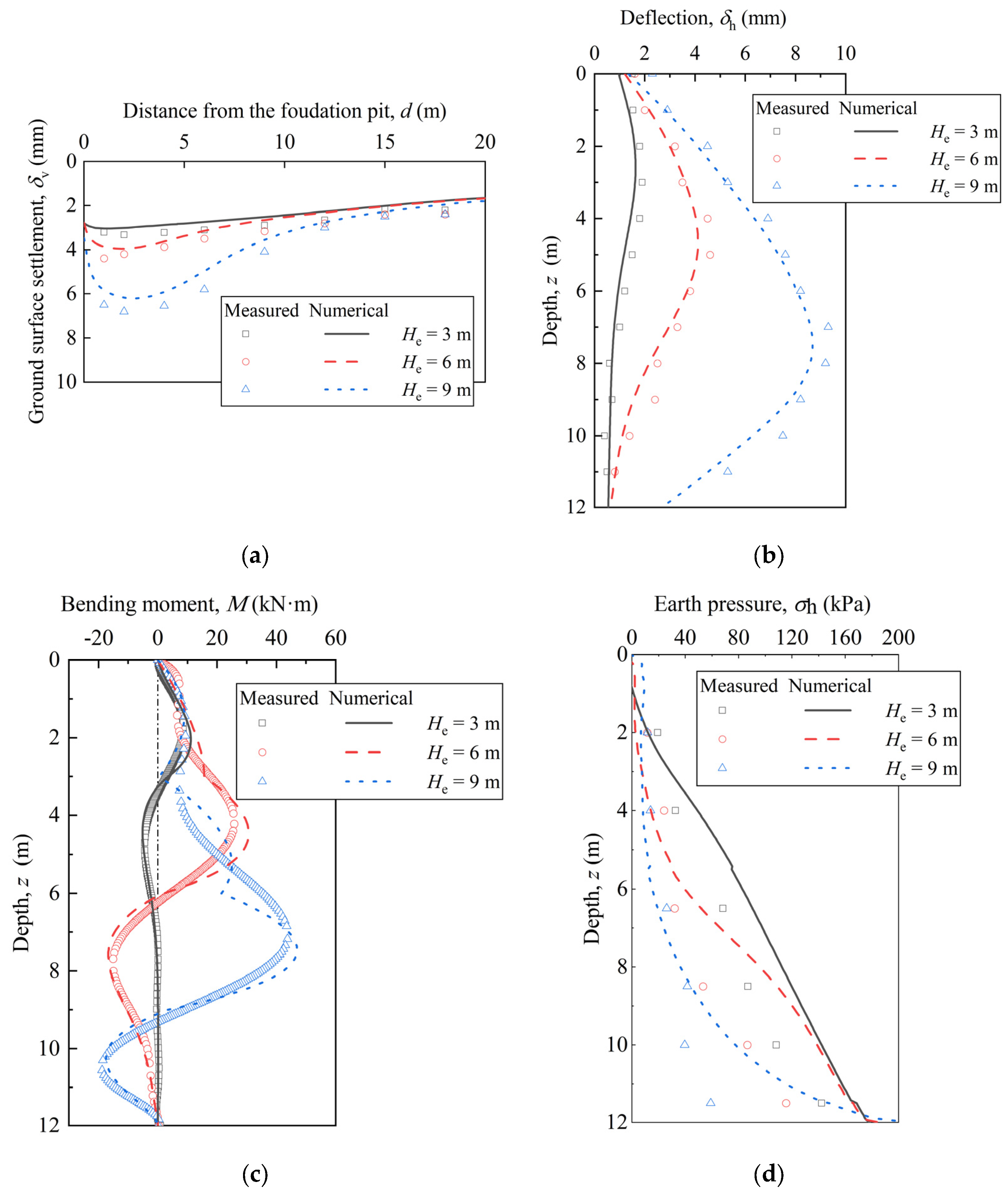
4.1. Comparison of Experimental and Numerical Results

To validate the numerical simulation, the observed and calculated results from various excavation stages are compared, as indicated in Figure 6. The deflections of the supporting piles exhibit a bulging profile. The maximum pile deflections measured during the three excavation stages were 1.9 mm, 4.6 mm, and 9.3 mm, while the simulation results indicated values of 1.6 mm, 4.1 mm, and 8.7 mm. Regarding ground surface settlement, the maximum measured values during the three excavation stages were 3.3 mm, 4.4 mm, and 6.8 mm, while simulation results showed maximum values of 3.0 mm, 4.0 mm, and 6.2 mm. The measured bending moments of the supporting piles corresponded closely with the numerical simulation results. However, a noticeable discrepancy exists between the simulated and measured earth pressures. This discrepancy can be attributed to the installation effects of the supporting piles, which resulted in measured earth pressures being lower than the simulated values [51,52]. The simulations did not account for these installation effects.
Overall, the numerical simulation reasonably captured the responses of the supporting structure and surrounding soil, indicating that the finite-element model, constitutive models, and input parameters used in this study are appropriate. Based on this model and its parameters, subsequent parametric analyses can explore how varying the excavation radius affects the stress and deformation of circular foundation pits supported by PRSSs.

4.2. Influence of Excavation Radius on Deformations

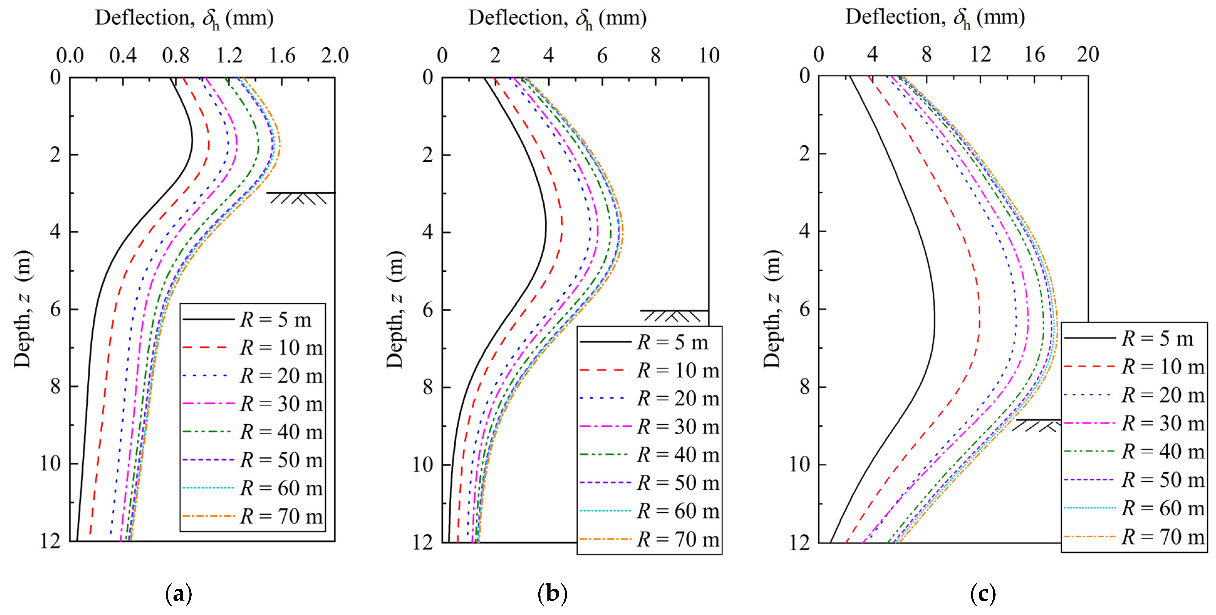
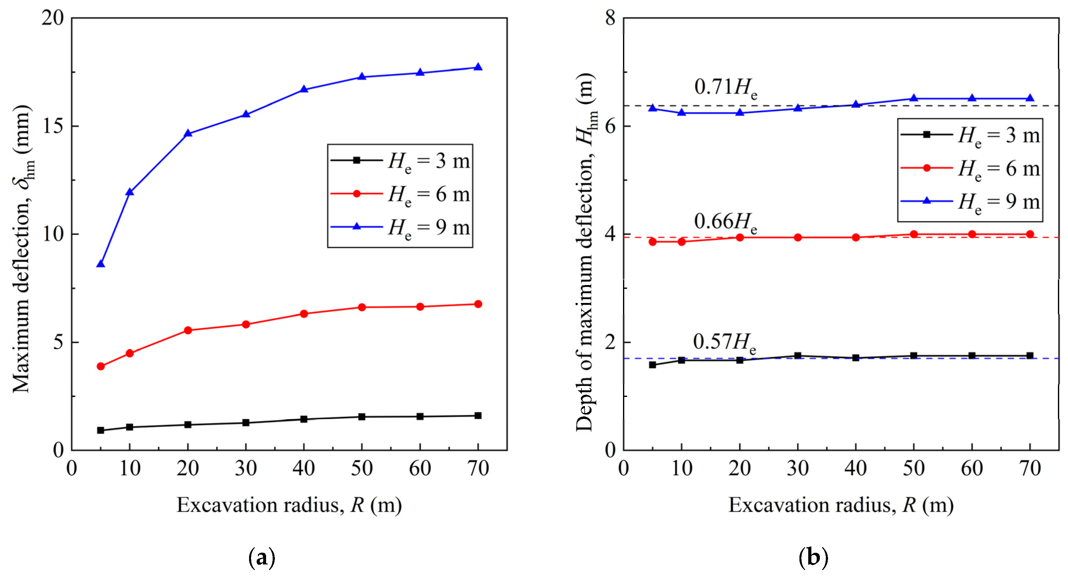
4.2.1. Deflections of Supporting Piles

Figure 7 presents the influence of excavation radius on pile deflection at different excavation depths. For a foundation pit of a given radius, as the excavation depth increases, the pile deflection increases, and its profile tends to exhibit a bulging type, similar to that of multipropped rectangular foundation pits [53,54,55]. At the same excavation depth, the pile deflection shape is generally consistent across different excavation radii, but its magnitude increases with larger radii. When the excavation radius is less than 50 m, the pile deflection significantly increases with the expanded excavation radius, but the increase rate gradually decreases. When the excavation radius is equal to or larger than 50 m, the variation in pile deflection with an increasing excavation radius is negligible. This indicates that the spatial arching effect of circular foundation pits, which plays a role in reducing pile deflection, decreases significantly as the excavation radius increases. Consequently, the advantage of circular foundation pits over other shapes in controlling horizontal displacements is less pronounced when the excavation radius exceeds 50 m, consistent with the findings reported by Tan et al. [22].
Figure 8 illustrates the variation in maximum pile deflection and its position with respect to the excavation radius during three excavation stages. At a constant excavation depth, the maximum deflection of the piles progressively increases as the excavation radius grows. However, the increase rate eventually diminishes, so when the excavation radius reaches 50 m, the maximum pile deflection tends to remain unchanged. Taking Stage 3 as an example, the maximum pile deflections at excavation radii of 10 m, 20 m, 30 m, 40 m, 50 m, 60 m, and 70 m are 1.39, 1.70, 1.81, 1.94, 2.01, 2.03, and 2.06 times those at 5 m, respectively. The rules describing pile deflection variations in Stages 1 and 2 are consistent with those observed in Stage 3. This phenomenon demonstrates that the impact of the excavation radius on pile deflection progressively attenuates as the excavation radius increases. In circular foundation pits with varying excavation depths, different retaining wall types, and disparate geologic conditions, the impact of excavation radius on retaining wall deflection is comparable. Furthermore, the maximum deflection position moves downward as the excavation depth increases. At a given excavation depth, the depth at which maximum pile deflection occurs remains relatively constant with an increased excavation radius. Under different excavation radii, the average maximum pile deflection depths at excavation depths of 3 m, 6 m, and 9 m are 0.57He, 0.66He, and 0.71He, respectively.
The plane strain ratio (PSR) is calculated as the largest displacement at the center of a retaining wall from three-dimensional analysis divided by the largest displacement from plane strain analysis [56]. It is widely used to study how excavation dimensions (such as length, width, and depth) affect excavation deformations [2,4,57]. Figure 9 depicts PSR variation with respect to excavation radius at varying excavation depths. The PSR value decreases as the excavation depth increases, a trend that is more pronounced with smaller excavation radii. Moreover, for a given excavation radius, the PSR value increases with an increasing radius and gradually converges to 1. At Stage 3 (He = 9 m), the PSR values significantly vary from 0.51 to 0.98 for excavation radii less than 50 m; however, for larger excavation radii (greater than 50 m), the PSR changes moderately within a range of 0.95 to nearly 1.00. This indicates that the spatial arching effect decreases with an increasing radius, resulting in the circular foundation pit approaching a plane strain state. Consequently, for shallow excavations and radii less than 50m, designs based on plane strain conditions are likely to be conservative.

4.2.2. Ground Surface Settlements

The correlation between ground surface settlement and excavation radius at different excavation stages is demonstrated in Figure 10. For a foundation pit with a given radius, ground surface settlement tends to increase with the deepening excavation, displaying a concave profile corresponding to the bulging deflection of the supporting piles [53,58,59]. When the excavation depth remains constant, increasing the excavation radius below 50 m significantly increases ground surface settlement, although the increase rate gradually diminishes. However, when the excavation radius exceeds 50 m, the change in ground surface settlement with increasing radius becomes negligible. The impact of excavation radius on ground surface settlement is similar to its impact on supporting pile deflection. Therefore, circular foundation pits demonstrate better control over horizontal and vertical deformation than rectangular pits when the excavation radius is less than 50 m. Notably, the influence of groundwater on the relationship between excavation radius and foundation pit deformation is not considered in the parametric analysis because, in the project reported in this study, the groundwater table was not progressively lowered in synchronization with the excavation process. Instead, the groundwater level in the foundation pit was intentionally lowered below the maximum excavation depth before excavation began. Therefore, unlike Figure 6a, Figure 10 shows no significant settlement in the ground surface beyond 15 m from the foundation pit when the radius is 5 m.
Figure 11 presents the changes in the maximum ground surface settlement and its location relative to the excavation radius across various excavation stages. The maximum ground surface settlement gradually increases at a given excavation depth with an increasing excavation radius. Nevertheless, the increase rate gradually decreases until the maximum ground surface settlement reaches a point of stabilization at a 50 m excavation radius. For example, at the third excavation stage, the maximum ground surface settlement values are 1.88, 2.67, 2.92, 3.18, 3.29, 3.31, and 3.34 times those at 5 m for excavation radii of 10 m, 20 m, 30 m, 40 m, 50 m, 60 m, and 70 m, respectively. The regulations regarding changes in ground surface settlement at Stages 1 and 2 are consistent with those observed at Stage 3. It can be inferred that as the excavation radius increases, its influence on maximum ground surface settlement decreases. The impact of excavation radius on maximum ground surface settlement is more pronounced when the radius is smaller. The impact of the radius on ground surface settlement remains considerable for circular foundation pits with varying excavation depths, retaining wall types, and geological conditions. Additionally, as excavation depth increases, the distance between the maximum ground surface settlement position and the foundation pit also increases. With a constant excavation depth, this distance grows with the excavation radius, but it reaches a stable value once the radius exceeds 30m. The stable values of the distances from the pit to the maximum ground surface settlement location are 0.52He, 0.50He, and 0.46He for excavation depths of 3 m, 6 m, and 9 m, respectively.
Referring to the PSR definition above, Figure 12 illustrates how the ratio of maximum ground surface settlement from an axisymmetric model (δvma) to that of a planar strain model (δvmp) varies with excavation radius (R). Variations in δvma/δvmp with excavation radius show similar trends to those of PSR with excavation radius. The trends imply that the excavation radii greater than 50 m result in an excavation response with a δvma/δvmp approximately equal to 1, suggesting that axisymmetric and plane strain analysis results will yield the same maximum ground surface settlement. Once again, it is demonstrated that as the radius increases, the spatial arching effect weakens, leading the circular foundation pit to approach a plane strain state. Furthermore, δvma/δvmp tends to decrease with increasing excavation depth, particularly for radii smaller than 50 m. Therefore, for circular deep excavations with radii greater than 50 m, the differences in results between the axisymmetric model and the plane strain model are negligible.

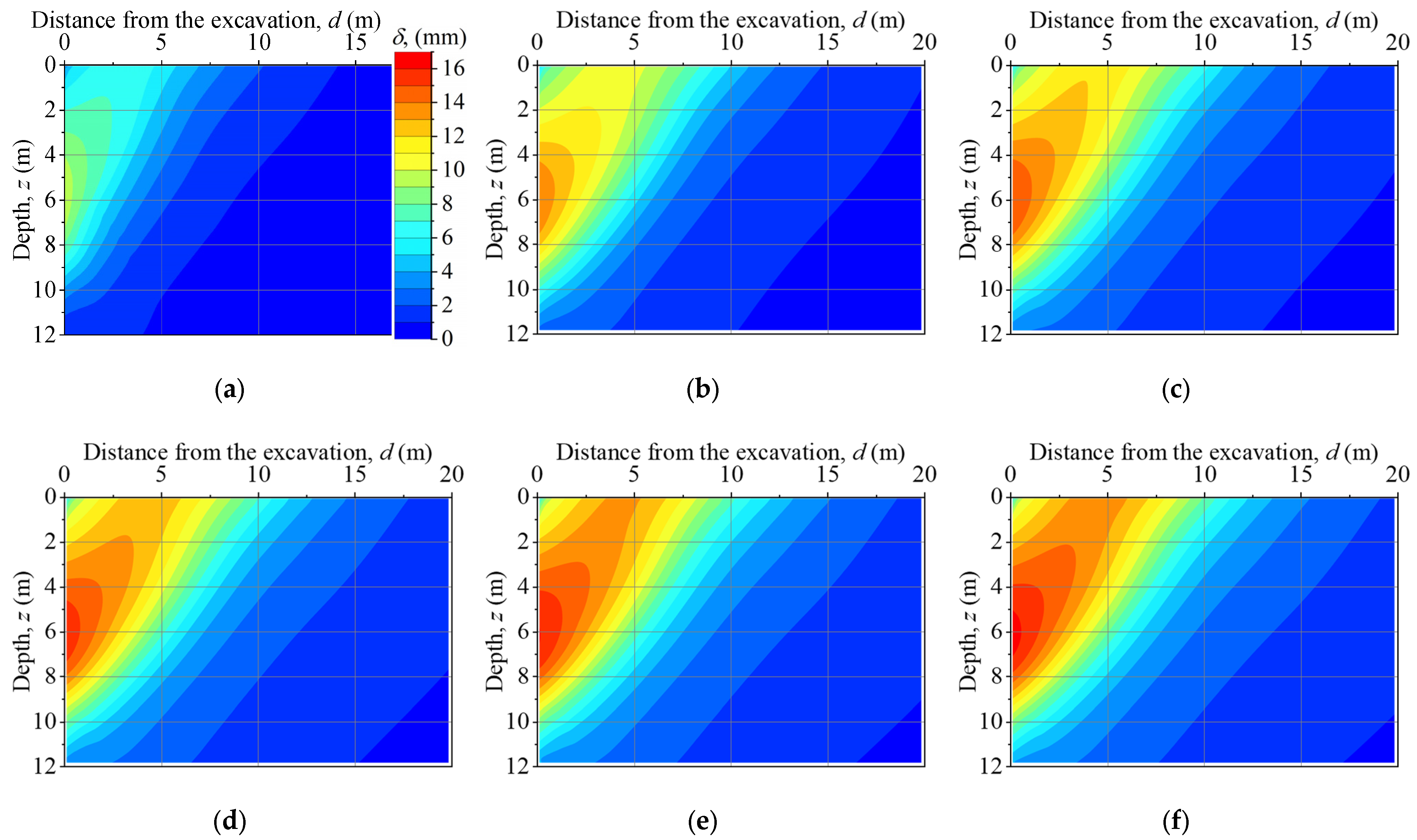
4.2.3. Total Ground Movements

Figure 13 illustrates contour plots of the total ground movements outside the foundation pit for different excavation radii at Stage 3 (He = 9 m). As the excavation radius increases, the total ground movements outside the pit gradually increase. Larger excavation radii lead to larger total ground movements and extend the influence areas. However, regardless of the excavation radius, the maximum total ground movement location always remains approximately 6 m below the ground surface in the vertical direction and near the wall in the horizontal direction. Once the excavation radius exceeds 50 m, the influence area, delineated by the 3 mm contour, the surface, and the supporting structure, does not change significantly, despite the continued expansion of the overall influence area with the excavation radius.

4.3. Influence of Excavation Radius on Stresses

4.3.1. Bending Moments of Supporting Piles

Figure 14 presents the variation in supporting pile bending moments with excavation radius at different depths. The supporting pile bending moment increases with both excavation depth and radius. Similar to the effect of excavation radius on supporting pile deflection, increases in excavation radius do not significantly change the supporting pile bending moments once the radius exceeds 50 m. The bending moments of the supporting piles at the positions connected to the walings are smaller than those at other positions. This suggests that in a circular foundation pit, the walings can effectively support the retaining walls. Consequently, the bulging deflections of the supporting piles in this unpropped circular foundation pit resemble those of multipropped rectangular foundation pits.
Figure 15 displays changes in the maximum bending moments of the supporting piles and their respective locations relative to the excavation radius across various excavation stages. At the same excavation depth, the maximum bending moment gradually increases with the excavation radius. Nevertheless, the increase rate diminishes as the excavation radius increases, and the maximum bending moment remains constant when the excavation radius exceeds 50 m. For instance, at Stage 3 (He = 9 m), the maximum bending moments increase to 1.22, 1.36, 1.46, 1.47, 1.48, 1.49, and 1.49 times those at a 5 m radius, corresponding to excavation radii of 10 m, 20 m, 30 m, 40 m, 50 m, 60 m, and 70 m, respectively. Similar trends in the variation in maximum bending moments with excavation radius can be observed at Stages 1 (He = 3 m) and 2 (He = 6 m). With deeper excavation, the maximum bending moment location moves downward. However, the depth at which the maximum bending moment occurs remains relatively unchanged with an increasing excavation radius at a given excavation depth. At Stages 1, 2, and 3, the average maximum bending moment depths vary as 0.67He, 0.74He, and 0.83He, respectively, for different excavation radii. Owing to the ring walings, the maximum bending moment occurs roughly midway between the two walings.

4.3.2. Earth Pressure

Figure 16 shows the variation in earth pressure distribution on the non-excavated side of the supporting pile with different excavation radii. The solid and dashed lines in the figure represent the axisymmetric and plane strain model results, respectively. As excavation progresses, the distribution of earth pressure along the depth changes from linear to nonlinear. Moreover, as the excavation deepens, the earth pressure borne by most parts of the supporting piles also decreases. The influence areas extend downward. However, for the supporting pile sections at depths not exceeding 4 m, the earth pressure decreases and then increases. This occurs because the supporting pile deformation gradually develops into a bulging shape (Figure 7), forming a vertical soil arching effect behind the supporting piles. The upper part of the retaining piles acts as the foot of the soil arch and is subject to greater earth pressure [60]. In the plane strain models, the earth pressure does not significantly vary with increasing excavation radius. However, in the axisymmetric models, the earth pressure increases with an increasing excavation radius, and this increase becomes more pronounced as the excavation depth increases. Overall, under identical conditions, the lateral earth pressure in axisymmetric models is lower than in plane strain models owing to the soil arching effect resulting from the circular foundation pit. This difference tends to increase with greater excavation depths and diminishes as the excavation radius increases. When the excavation radius exceeds 50 m, the difference in earth pressure between the axisymmetric models and the plane strain models is negligible.

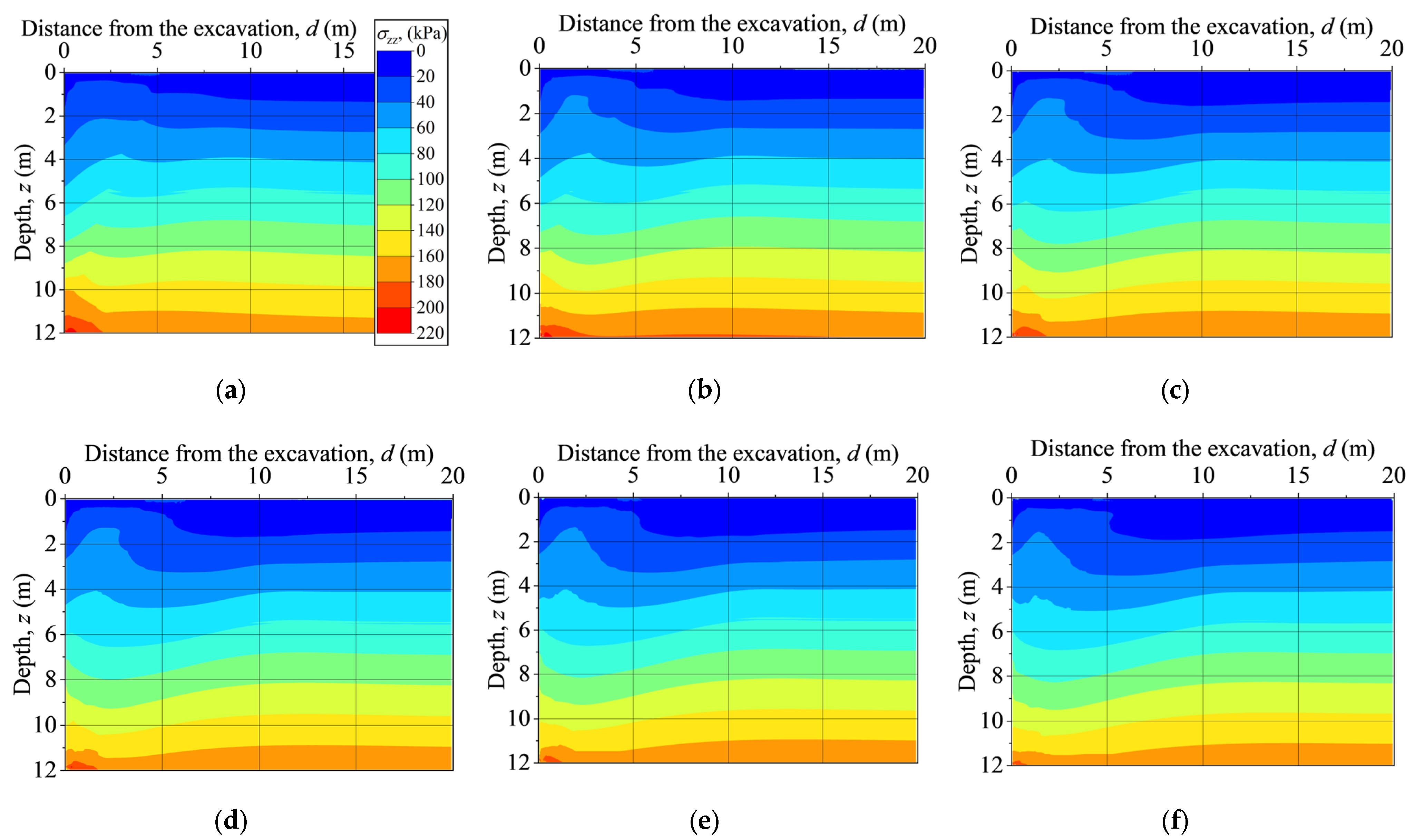
4.3.3. Circumferential Stress

Figure 17 presents the variation in circumferential stress with excavation radius at the final excavation stage. The circular foundation pit deformations are closely related to the circumferential stress distribution since the circumferential stress affects the soil strength and the plastic zone size [17,19,61,62]. The circumferential stresses in the majority of the area affected by the excavation decrease with increasing radius. When the excavation radius exceeds 50 m, its effect on circumferential stress becomes insignificant. This suggests that the circular foundation pit spatial arching effect tends to diminish as the excavation radius increases. Furthermore, this change in circumferential stresses provides an alternative explanation for the observation that, when the radius exceeds 50 m, the foundation pit deformations tend to stabilize. The axisymmetric model results are roughly equal to those from the plane strain models.

4.4. Influence of Excavation Radius on Stability

Figure 18 illustrates the safety factor (S) for varying excavation radii at the final excavation stage in both axisymmetric and plane strain conditions. The safety factor calculated from the axisymmetric models nonlinearly decreases as the excavation radius increases. As the excavation radius increases, the decrease rate in the safety factor slows down. By contrast, the safety factor obtained from the plane strain models remains relatively constant with increasing excavation radii. Furthermore, as the excavation radius increases, the safety factor under the symmetric condition tends to approach that under the plane strain condition because, as the excavation radius increases, the spatial arching effect produced by the circular excavation gradually ceases to be significant. Once the excavation radius surpasses 50 m, the safety factor derived from both the axisymmetric and plane strain models becomes largely comparable. It is important to note that various regions may have specific codes dictating minimum factors of safety based on structural type and environmental conditions. The relationship between the factor of safety and excavation radius in Figure 18 is relevant to foundation pits supported by PRSSs in silty clay. Current design methods typically calculate the factor of safety for circular foundation pits based on the plane strain assumption. Engineers can derive the factors of safety under axisymmetric conditions from plane strain results, facilitating a more economical design.

5. Conclusions

This paper presents a comprehensive study of the influence of excavation radius on the behavior of circular foundation pits supported by PRSSs. A full-scale experiment and a series of numerical simulations were performed to analyze the stress, deformation, and stability of a circular foundation pit. According to the analysis results, the following conclusions can be drawn:
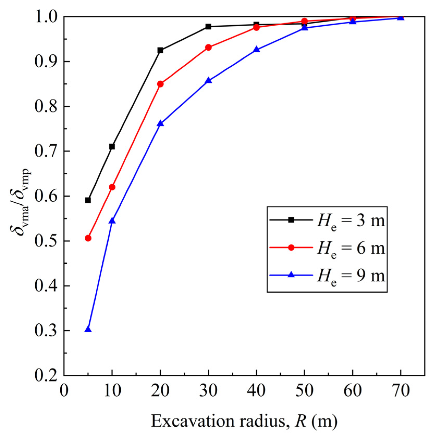
  • The deflection and bending moment of the supporting pile increase significantly with an increasing excavation radius; however, the increase rate gradually slows down, making the change in deflection and the bending moment insignificant when the excavation radius exceeds 50 m. Nevertheless, the excavation radius has little effect on the depth at which the maximum pile deflection and bending moment occur. In addition, the PSR value increases with an increasing excavation radius and gradually converges to 1.
  • As with its influence on pile deflection, increasing the excavation radius results in greater ground surface settlement. Nevertheless, once the excavation radius is beyond 50 m, this influence becomes less pronounced, and the differences in ground surface settlement predictions using axisymmetric and planar strain models are minimal. Moreover, the distance from the maximum settlement point to the foundation pit increases with radius but stabilizes once the radius exceeds 30 m.
  • In axisymmetric models, the lateral earth pressure on the non-excavation side of the supporting pile increases as the excavation radius increases. In excavation radii exceeding 50 m, the discrepancy between the earth pressures calculated using the axisymmetric and plane strain models is negligible.
  • Circumferential stresses in the majority of the area affected by the excavation decrease with an increasing excavation radius. Once the excavation radius surpasses 50 m, its impact on circumferential stress becomes insignificant.
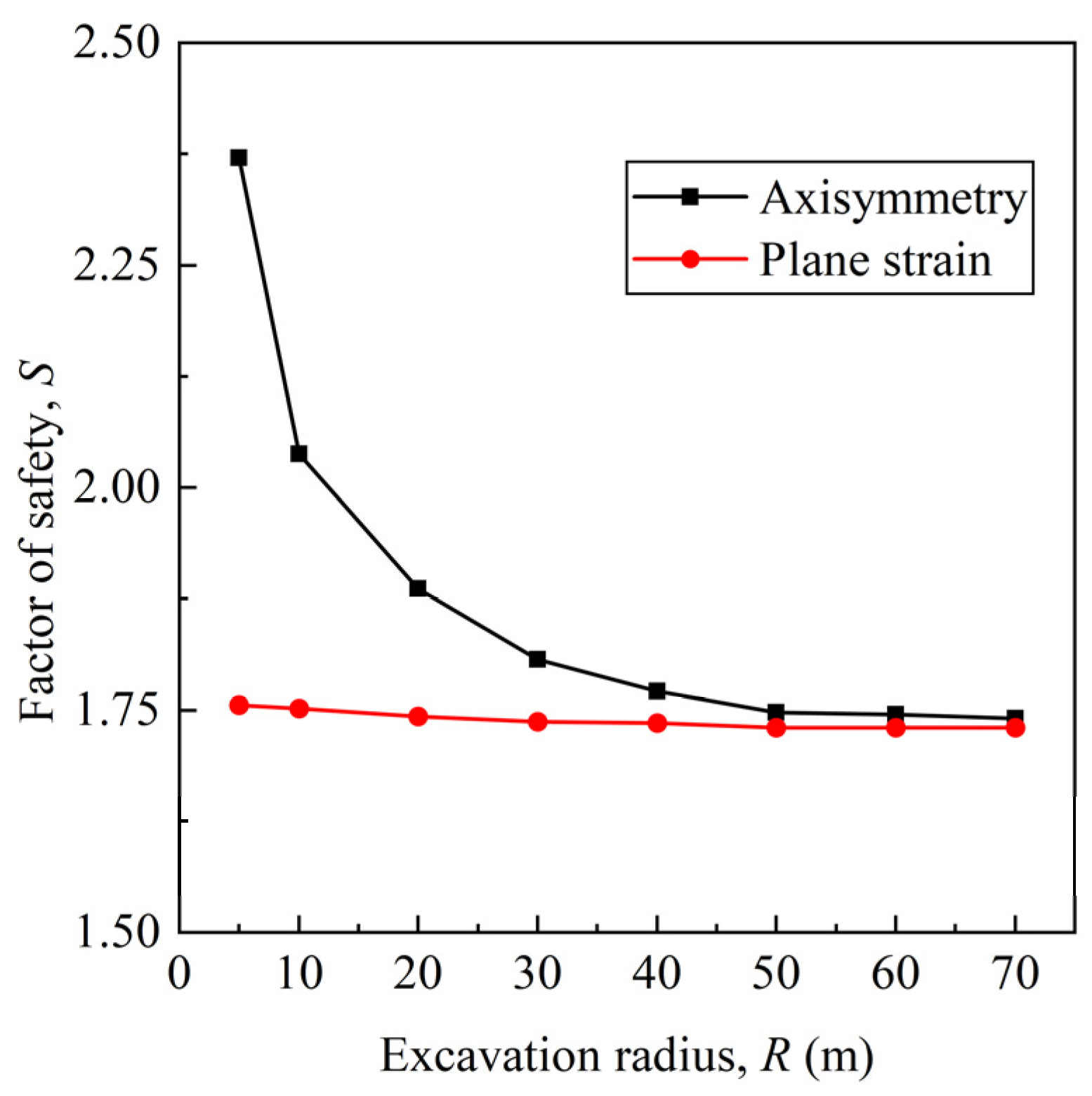
  • When the radius of a circular foundation pit is less than 50 m, a larger excavation radius correlates with a smaller safety factor. However, when the excavation radius is more than 50 m, the safety factor under axisymmetric conditions remains constant and approaches that under plane strain conditions.
Due to site condition limitations, the full-scale experiments and related numerical simulations in this study were conducted in silty clay. Further efforts are required to investigate the influence of excavation radius on the behavior of circular foundation pits under various geological conditions.

Author Contributions

Conceptualization, C.G. and Y.P.; software, L.C.; methodology, L.C. and Y.P.; validation, L.C.; formal analysis, L.C.; investigation, L.C., Y.P., and M.T.; resources, C.G.; data curation, L.C.; writing—original draft preparation, L.C.; writing—review and editing, C.G., Y.P. and K.Z.; visualization, L.C.; supervision, C.G., H.L., and Y.P.; project administration, H.L., Y.P., and M.T.; funding acquisition, C.G., M.T., and H.L. All authors have read and agreed to the published version of the manuscript.

Funding

This research was funded by the Science and Technology Program of Guangzhou Municipal Construction Group Co., Ltd., China, grant number 2022-KJ004. The funder had the following involvement with the study: the construction and monitoring of the PRSS.

Institutional Review Board Statement

Not applicable.

Informed Consent Statement

Not applicable.

Data Availability Statement

The data presented in this study are available on request from the corresponding author due to restrictions on privacy.

Conflicts of Interest

Authors Huqing Liang and Mengxiong Tang were employed by the company Guangzhou Municipal Construction Group Co., Ltd. The remaining authors declare that the research was conducted in the absence of any commercial or financial relationships that could be construed as a potential conflict of interest.

References

  1. Tan, Y.; Fan, D.; Lu, Y. Statistical Analyses on a Database of Deep Excavations in Shanghai Soft Clays in China from 1995–2018. Pract. Period. Struct. Des. Constr. 2022, 27, 4021067. [Google Scholar] [CrossRef]
  2. Hsiung, B.B.; Likitlersuang, S.; Phan, K.H.; Pisitsopon, P. Impacts of the plane strain ratio on excavations in soft alluvium deposits. Acta Geotech. 2021, 16, 1923–1938. [Google Scholar] [CrossRef]
  3. JGJ 120-2012; Technical Specification for Retaining and Protection of Building Foundation Excavations. China Architecture & Building Press: Beijing, China, 2012.
  4. Finno, R.J.; Blackburn, J.T.; Roboski, J.F. Three-Dimensional Effects for Supported Excavations in Clay. J. Geotech. Geoenviron. Eng. 2007, 133, 30–36. [Google Scholar] [CrossRef]
  5. Cheng, K.; Xu, R.; Ying, H.; Gan, X.; Zhang, L.; Liu, S. Observed performance of a 30.2 m deep-large basement excavation in Hangzhou soft clay. Tunn. Undergr. Space Technol. 2021, 111, 103872. [Google Scholar] [CrossRef]
  6. Galliková, Z.; Rehman, Z.U. Appraisal of the hypoplastic model for the numerical prediction of high-rise building settlement in Neogene clay based on real-scale monitoring data. J. Build. Eng. 2022, 50, 104152. [Google Scholar] [CrossRef]
  7. Liu, Y.; Huang, F.; Wang, G.; Cao, Y.; Li, B. Study on Long-Span and Variable-Section Foundation Pit Excavation in Muddy Silty Clay. Int. J. Civ. Eng. 2024, 22, 739–755. [Google Scholar] [CrossRef]
  8. Sun, Y.; Gu, Z.; Xu, Z.; Wang, C.; Song, D. Performance of a long, irregular top-down excavation in the centre of Nanjing, China. Proc. Inst. Civ. Eng. -Geotech. Eng. 2022, 177, 50–65. [Google Scholar] [CrossRef]
  9. Mana, A.I.; Clough, G.W. Prediction of Movements for Braced Cuts in Clay. J. Geotech. Eng. Div. 1981, 107, 759–777. [Google Scholar] [CrossRef]
  10. Wang, H. Influence of excavation width on enclosure-structure stability of foundation pits. China Civ. Eng. J. 2011, 44, 120–126. [Google Scholar] [CrossRef]
  11. Xiao, H.; Zhou, S.; Sun, Y. Wall Deflection and Ground Surface Settlement due to Excavation Width and Foundation Pit Classification. KSCE J. Civ. Eng. 2019, 23, 1537–1547. [Google Scholar] [CrossRef]
  12. Park, C.; Joung, S. Numerical investigations on the excavation width and property of deformation of earth retaining wall. J. Korean Geotech. Soc. 2020, 36, 57–68. [Google Scholar] [CrossRef]
  13. Tan, Y.; Wang, D. Characteristics of A Large-Scale Deep Foundation Pit Excavated by Central-Island Technique in Shanghai Soft Clay. Part II: Top-Down Construction of the Peripheral Rectangular Pit. J. Geotech. Geoenviron. Eng. 2013, 139, 1894–1910. [Google Scholar] [CrossRef]
  14. Zeng, C.; Zheng, G.; Zhou, X.; Xue, X.; Zhou, H. Behaviours of wall and soil during pre-excavation dewatering under different foundation pit widths. Comput. Geotech. 2019, 115, 103169. [Google Scholar] [CrossRef]
  15. Huang, P.; Dang, K.; Shi, H.; Yang, K.; Wu, J. Influence and Mechanism of the Excavation Width on Excavation Deformations in Shanghai Soft Clay. Buildings 2024, 14, 1450. [Google Scholar] [CrossRef]
  16. Kim, K.; Lee, D.; Cho, J.; Jeong, S.; Lee, S. The effect of arching pressure on a vertical circular shaft. Tunn. Undergr. Space Technol. 2013, 37, 10–21. [Google Scholar] [CrossRef]
  17. Schwamb, T.; Soga, K. Numerical modelling of a deep circular excavation at Abbey Mills in London. Géotechnique 2015, 65, 604–619. [Google Scholar] [CrossRef]
  18. Qiao, Y.; Xie, F.; Bai, Z.; Lu, J.; Ding, W. Deformation characteristics of ultra-deep circular shaft in soft soil: A case study. Undergr. Space 2024, 16, 239–260. [Google Scholar] [CrossRef]
  19. Tangjarusritaratorn, T.; Miyazaki, Y.; Sawamura, Y.; Kishida, K.; Kimura, M. Numerical investigation on arching effect surrounding deep cylindrical shaft during excavation process. Undergr. Space 2022, 7, 944–965. [Google Scholar] [CrossRef]
  20. Tobar, T.; Meguid, M.A. Experimental Study of the Earth Pressure Distribution on Cylindrical Shafts. J. Geotech. Geoenviron. Eng. 2011, 137, 1121–1125. [Google Scholar] [CrossRef]
  21. Herten, M.; Pulsfort, M. Determination of spatial earth pressure on circular shaft constructions. Granul. Matter 1999, 2, 1–7. [Google Scholar] [CrossRef]
  22. Tan, Y.; Wang, D. Characteristics of a Large-Scale Deep Foundation Pit Excavated by the Central-Island Technique in Shanghai Soft Clay. I: Bottom-Up Construction of the Central Cylindrical Shaft. J. Geotech. Geoenviron. Eng. 2013, 139, 1875–1893. [Google Scholar] [CrossRef]
  23. Cheng, Y.M.; Hu, Y.Y.; Wei, W.B. General Axisymmetric Active Earth Pressure by Method of Characteristics—Theory and Numerical Formulation. Int. J. Geomech. 2007, 7, 1–15. [Google Scholar] [CrossRef]
  24. Cho, J.; Lim, H.; Jeong, S.; Kim, K. Analysis of lateral earth pressure on a vertical circular shaft considering the 3D arching effect. Tunn. Undergr. Space Technol. 2015, 48, 11–19. [Google Scholar] [CrossRef]
  25. Meftah, A.; Benmebarek, N.; Benmebarek, S. Numerical study of the active earth pressure distribution on cylindrical shafts using 2D finite difference code. J. Appl. Eng. Sci. Technol. 2018, 4, 123–128. [Google Scholar]
  26. Liu, G.; Meng, H.; Song, G.; Bo, W.; Zhao, P.; Ning, B.; Xu, X. Numerical simulation of wedge failure of rock slopes using three-dimensional discontinuous deformation analysis. Environ. Earth Sci. 2024, 83, 310. [Google Scholar] [CrossRef]
  27. Zhang, J.; Li, Y.; Zhang, C. Pounding induced overturning resistance of FPB-isolated structures considering soil-structure-interactions. Soil Dyn. Earthq. Eng. 2024, 177, 108416. [Google Scholar] [CrossRef]
  28. Keshavarz, A.; Ebrahimi, M. Axisymmetric passive lateral earth pressure of retaining walls. KSCE J. Civ. Eng. 2017, 21, 1706–1716. [Google Scholar] [CrossRef]
  29. Guo, C.; Ye, J.; Zhao, C.; Wang, F. Mechanical and deformation characteristics of composite assembled supporting structure. Geotech. Res. 2020, 7, 230–243. [Google Scholar] [CrossRef]
  30. Hu, D.; Guo, C.; Chu, X. Case Study of Flexible Prefabricated Impermeable Underground Support Structure. Iran. J. Sci. Technol. Trans. Civ. Eng. 2021, 45, 2489–2501. [Google Scholar] [CrossRef]
  31. Huang, H.; Yuan, Y.; Zhang, W.; Li, M. Seismic behavior of a replaceable artificial controllable plastic hinge for precast concrete beam-column joint. Eng. Struct. 2021, 245, 112848. [Google Scholar] [CrossRef]
  32. Cao, J.; Du, J.; Fan, Q.; Yang, J.; Bao, C.; Liu, Y. Reinforcement for earthquake-damaged glued-laminated timber knee-braced frames with self-tapping screws and CFRP fabric. Eng. Struct. 2024, 306, 117787. [Google Scholar] [CrossRef]
  33. Pan, Y.; Fang, H.; Li, B.; Wang, F. Stability analysis and full-scale test of a new recyclable supporting structure for underground ecological granaries. Eng. Struct. 2019, 192, 205–219. [Google Scholar] [CrossRef]
  34. Chen, L.; Guo, C.; Cao, D. Numerical Investigation of Earth Berm Effects on Prefabricated Recyclable Supporting Structure in Circular Excavations. Appl. Sci. 2024, 14, 4703. [Google Scholar] [CrossRef]
  35. Huang, H.; Li, M.; Zhang, W.; Yuan, Y. Seismic behavior of a friction-type artificial plastic hinge for the precast beam–column connection. Arch. Civ. Mech. Eng. 2022, 22, 201. [Google Scholar] [CrossRef]
  36. Huang, H.; Li, M.; Yuan, Y.; Bai, H. Experimental Research on the Seismic Performance of Precast Concrete Frame with Replaceable Artificial Controllable Plastic Hinges. J. Struct. Eng. 2023, 149, 4022222. [Google Scholar] [CrossRef]
  37. GB 50497-2019; Technical standard for monitoring of building excavation engineering. Ministry Of Housing And Urban-Rural Development of the People’s Republic of China, China Architecture & Building Press: Beijing, China, 2019.
  38. Wang, F.; Chen, L.; Pan, Y.; Guo, C.; Guo, C.; Yue, L.; Chu, X. Deformation characteristics of excavation supported by prefabricated recyclable structures. Proc. Inst. Civ. Eng. -Geotech. Eng. 2024, ahead of print, 1–43. [Google Scholar] [CrossRef]
  39. Zhou, H.; Zheng, G.; He, X.; Wang, E.; Guo, Z.; Nie, D.; Ma, S. Numerical modelling of retaining structure displacements in multi-bench retained excavations. Acta Geotech. 2020, 15, 2691–2703. [Google Scholar] [CrossRef]
  40. Brinkgreve, R.; Kumarswamy, S.; Swolfs, W.M.; Waterman, D.; Chesaru, A.; Bonnier, P.G. PLAXIS 2016; PLAXIS bv: Delft, The Netherlands, 2016. [Google Scholar]
  41. Benz, T. Small-Strain Stiffness of Soils and Its Numerical Consequences; University of Sturrgart: Stuttgart, Germany, 2007. [Google Scholar]
  42. Zhang, W.; Goh, A.T.C.; Xuan, F. A simple prediction model for wall deflection caused by braced excavation in clays. Comput. Geotech. 2015, 63, 67–72. [Google Scholar] [CrossRef]
  43. Nejjar, K.; Dias, D.; Cuira, F.; Chapron, G.; Le Bissonnais, H. Numerical modelling of a 32 m deep excavation in the suburbs of Paris. Eng. Struct. 2022, 268, 114727. [Google Scholar] [CrossRef]
  44. Hardin, B.O.; Drnevich, V.P. Shear Modulus and Damping in Soils: Design Equations and Curves. J. Soil Mech. Found. Div. 1972, 98, 667–692. [Google Scholar] [CrossRef]
  45. Di Mariano, A.; Amoroso, S.; Arroyo, M.; Monaco, P.; Gens, A. SDMT-Based Numerical Analyses of Deep Excavation in Soft Soil. J. Geotech. Geoenviron. Eng. 2019, 145, 04018102. [Google Scholar] [CrossRef]
  46. Brinkgreve, R.B. Selection of soil models and parameters for geotechnical engineering application. In Soil Constitutive Models: Evaluation, Selection, and Calibration; American Society of Civil Engineers: Austin, TX, USA, 2005; pp. 69–98. [Google Scholar]
  47. Rehman, Z.U.; Zhang, G. Shear coupling effect of monotonic and cyclic behavior of the interface between steel and gravel. Can. Geotech. J. 2018, 56, 876–884. [Google Scholar] [CrossRef]
  48. Potyondy, J.G. Skin friction between various soils and construction materials. Géotechnique 1961, 11, 339–353. [Google Scholar] [CrossRef]
  49. GB/T 11263-2017; Hot-Rolled H Sections and Cut T Sections. S.A.O. of the People’s Republic Of China, China Architecture & Building Press: Beijing, China, 2017.
  50. Mishra, A.; Sawant, V.A. A Detailed Investigation on Contiguous Pile Wall with Homogeneous Backfill. Geotech. Geol. Eng. 2023, 41, 2065–2089. [Google Scholar] [CrossRef]
  51. Richards, D.J.; Clark, J.; Powrie, W. Installation effects of a bored pile wall in overconsolidated clay. Géotechnique 2006, 56, 411–425. [Google Scholar] [CrossRef]
  52. Duan, N.; Cheng, Y.P.; Liu, J.W. DEM analysis of pile installation effect: Comparing a bored and a driven pile. Granul. Matter 2018, 20, 1–16. [Google Scholar] [CrossRef]
  53. Ou, C.; Hsieh, P.; Chiou, D. Characteristics of ground surface settlement during excavation. Can. Geotech. J. 1993, 30, 758–767. [Google Scholar] [CrossRef]
  54. Ni, X.; Lu, J.; Wang, Y.; Shi, J.; Chen, W.; Tang, L. Field investigation of the influence of basement excavation and dewatering on ground and structure responses. Tunn. Undergr. Space Technol. 2021, 117, 104121. [Google Scholar] [CrossRef]
  55. Feng, Z.; Xu, Q.; Xu, X.; Tang, Q.; Li, X.; Liao, X. Deformation Characteristics of Soil Layers and Diaphragm Walls during Deep Foundation Pit Excavation: Simulation Verification and Parameter Analysis. Symmetry 2022, 14, 254. [Google Scholar] [CrossRef]
  56. Ou, C.; Chiou, D.; Wu, T. Three-Dimensional Finite Element Analysis of Deep Excavations. J. Geotech. Eng. 1996, 122, 337–345. [Google Scholar] [CrossRef]
  57. Lu, T.; Wu, K.; Liu, S.; Cai, G. Method for estimating three-dimensional effects on braced excavation in clay. Tunn. Undergr. Space Technol. 2023, 141, 105355. [Google Scholar] [CrossRef]
  58. Zhao, J.; Tan, Z.; Yu, R.; Li, Z.; Zhang, X.; Zhu, P. Deformation responses of the foundation pit construction of the urban metro station: A case study in Xiamen. Tunn. Undergr. Space Technol. 2022, 128, 104662. [Google Scholar] [CrossRef]
  59. Maher, T.; Basha, A.M.; Abo-Raya, M.M.; Zakaria, M.H. General deformation behavior of deep excavation support systems: A review. Glob. J. Eng. Technol. Adv. 2022, 10, 39–57. [Google Scholar] [CrossRef]
  60. Yang, K.; Li, Z.; Chen, Y.; Yang, X.; Lin, W. Soil Arching–Induced Lateral Earth Pressure Redistribution on the Retaining Wall in a Multistrutted Excavation in Soft Soil. J. Geotech. Geoenviron. Eng. 2023, 149, 5023004. [Google Scholar] [CrossRef]
  61. Schanz, T.; Vermeer, P.A.; Bonnier, P.G. Formulation and verification of the Hardening-Soil Model. In Beyond 2000 in Computational Geotechnics; Routledge: Rotterdam, The Netherlands, 1999. [Google Scholar]
  62. Xiong, G.; Wang, J. A rigorous characteristic line theory for axisymmetric problems and its application in circular excavations. Acta Geotech. 2020, 15, 439–453. [Google Scholar] [CrossRef]
Figure 1. The circular foundation pit supported by PRSSs: (a) schematic diagram of profile view; (b) aerial top view.
Buildings 14 03110 g001
Figure 2. Construction process: (a) installing supporting piles; (b) installing first-layer waling; (c) installing steel plates; (d) excavating soil and installing second-layer waling; (e) injecting polyurethane behind the steel plates; (f) repeating steps (d,e) until the final depth is reached.
Buildings 14 03110 g002
Figure 3. Instrumentation layout: (a) plane view; (b) cross-section view.
Buildings 14 03110 g003
Figure 4. Instrumentation details.
Buildings 14 03110 g004
Figure 5. Typical FE models: (a) axisymmetric condition; (b) plane strain condition.
Buildings 14 03110 g005
Figure 6. Comparison of measured and numerical results: (a) ground surface settlement; (b) deflection of supporting pile; (c) bending moment of supporting pile; (d) earth pressure.
Buildings 14 03110 g006
Figure 7. Variation in pile deflection with excavation radius at different excavation depths: (a) He = 3 m; (b) He = 6 m; (c) He = 9 m.
Buildings 14 03110 g007
Figure 8. Variation in maximum pile deflection and its position with radius at different excavation stages: (a) maximum pile deflection; (b) depth of maximum pile deflection.
Buildings 14 03110 g008
Figure 9. Variation in PSR with excavation radius at different excavation depths.
Buildings 14 03110 g009
Figure 10. Variation in ground surface settlements with excavation radius: (a) He = 3 m; (b) He = 6 m; (c) He = 9 m.
Buildings 14 03110 g010aBuildings 14 03110 g010b
Figure 11. Variation in maximum ground surface settlement and its position with radius at different excavation stages: (a) maximum pile deflection; (b) distance from the maximum ground settlement location to the foundation pit.
Buildings 14 03110 g011
Figure 12. Variation in δvma/δvmp with excavation radius at different excavation stages.
Buildings 14 03110 g012
Figure 13. Contour plots of the total ground movements outside the foundation pit for different excavation radii at Stage 3: (a) R = 10 m; (b) R = 20 m; (c) R = 30 m; (d) R = 40 m; (e) R = 50 m; (f) R = 60 m.
Buildings 14 03110 g013
Figure 14. Variation in bending moments with excavation radius at different depths: (a) He = 3 m; (b) He = 6 m; (c) He = 9 m.
Buildings 14 03110 g014
Figure 15. Variation in maximum bending moments and their locations with radii at different excavation stages: (a) maximum bending moments; (b) depths of maximum bending moments.
Buildings 14 03110 g015
Figure 16. Variation in earth pressure distribution on the non-excavated side of the supporting pile with excavation radius: (a) R = 10 m; (b) R = 20 m; (c) R = 30 m; (d) R = 40 m; (e) R = 50 m; (f) R = 60 m.
Buildings 14 03110 g016
Figure 17. Contour plots of circumferential stress: (a) R = 10 m; (b) R = 20 m; (c) R = 30 m; (d) R = 40 m; (e) R = 50 m; (f) R = 60 m.
Buildings 14 03110 g017
Figure 18. Correlation between the safety factor and the excavation radius under axisymmetric and plane strain conditions.
Buildings 14 03110 g018
Table 1. Basic parameters of soil layers at the site.
Soil LayersUnit Weight,
γ (kN/m3)
Water Content,
w (%)
Void Ratio,
e
Effective Cohesion,
c’,
(kPa)
Effective Friction Angle,
φ’ (°)
Plasticity Index,
IP (%)
Liquidity Index,
IL
Compression Modulus,
Es (MPa)
Cone Resistance in CPT,
qc (MPa)
Blow Count of SPT,
N
Permeability Coefficient,
Κ (m/day)
19.1823.60.71928.513.312.70.387.7614.50.08
19.4323.80.70431.614.213.90.338.091.310.30.08
19.1824.70.73830.813.413.90.338.372.28.90.12
19.3823.30.70231.514.613.80.299.011.816.40.09
Table 2. Soil parameters for the HSS model used in the numerical analyses.
Soil LayersTangent Referential Stiffness,
E o e d r e f (MPa)
Secant Referential Stiffness,
E 50 r e f (MPa)
Unloading
–Reloading Referential Stiffness,
E u r r e f (MPa)
Poisson’s Ratio for Unloading-Reloading,
v u r
Reference Shear Modulus at Very Small Strains,
G 0 r e f (kN/m2)
Shear Strain for 70% of G0,
γ 0.7 (10−4)
Power for Stress-Level Dependency of Stiffness,
m
Failure Ratio,
R f
Interface Reduction Factor,
R int er
7.767.7623.280.297.272.591.00.90.65
8.098.0924.270.299.442.481.00.90.65
8.378.3725.110.294.592.621.00.90.65
9.019.0127.030.299.732.871.00.90.65
Table 3. Structural parameters used for numerical analyses.
Structural ElementElement TypeMaterial TypeAxis Stiffness of the
Anchor or the In-Plane Axis Stiffness of the Plate
EA1 (kN)
Out-of-Plane Axis Stiffness,
EA2 (kN)
Flexural Rigidity
EI (kN·m2)
Spacing of Supporting Piles
Lspacing (m)
Supporting structurePlateElastic2.31 × 10605.22 × 104--
WalingAnchorElastic1.43 × 105----1.57
Disclaimer/Publisher’s Note: The statements, opinions and data contained in all publications are solely those of the individual author(s) and contributor(s) and not of MDPI and/or the editor(s). MDPI and/or the editor(s) disclaim responsibility for any injury to people or property resulting from any ideas, methods, instructions or products referred to in the content.

