Article

Axial Compression Damage Model and Damage Evolution of Crumb Rubber Concrete Based on the Energy Method

College of Civil Engineering, Inner Mongolia University of Science and Technology, Baotou 014010, China
*
Author to whom correspondence should be addressed.
Buildings 2024, 14(3), 705; https://doi.org/10.3390/buildings14030705
Submission received: 30 January 2024 / Revised: 28 February 2024 / Accepted: 4 March 2024 / Published: 6 March 2024
(This article belongs to the Special Issue Research on Properties and Usage of Construction Composite Materials)

Abstract

:
The current constitutive model and damage evolution law of crumb rubber concrete (CRC) were obtained by fitting and changing parameters based on the normal concrete model. However, this model does not accurately reflect the characteristics of the material. In this paper, we studied the energy dissipation in the failure process of CRC to derive the constitutive model and damage evolution law of CRC based on the energy method. Four substitution rates of 5%, 10%, 15%, and 20% were selected, and the rubber concrete prism was prepared by replacing the natural fine aggregate with the same volume of crumb rubber aggregate. After that, uniaxial compressive tests were conducted. The energy lost due to the damage was calculated and analyzed, and the energy method was used to establish the damage evolution law and damage model of the crumb rubber concrete. The results demonstrated that the Guo Zhenhai damage model, which is based on the energy method, can more effectively explain the crumb rubber concrete stress–strain full curve, and the energy consumed as a result of the damage exhibits a growing and then reducing pattern with the increase in rubber doses. When the energy-based method is used, the Guo Zhenhai damage evolution model is similar to the damage evolution law calculated using the SIR damage evolution model. During uniaxial compression damage, rubber concrete with various rubber dosages demonstrated varying energy absorption in different deformation phases. When the rubber particle content was 10%, the energy absorption capacity of the specimen was 6.9% higher than that of normal concrete.

1. Introduction

China’s automobile industry has undergone rapid development in recent years, with the national rate of car ownership increasing from 281 million in 2020 to 417 million in 2022 [1]. The number of waste tires has increased accordingly, becoming the main source of waste rubber, which is a waste of resources and a major source of environmental pollution [2]. The utilization rate of waste tires in China is only 60%, which is far lower than the utilization rate of 90% or more that has been observed in developed countries [3]. Proper handling of scrap tires is an environmental issue that requires attention. In order to alleviate the shortage of resources, solid waste is widely utilized in concrete, as demonstrated by research on the frost resistance of concrete prepared using nano-modified recycled aggregate [4] and research on the macroscopic and microscopic properties of steel slag concrete prepared using steel slag instead of fine aggregates [5]. The preparation of rubber concrete using rubber chips opens up a new channel for the resource utilization of waste tires [3]. Rubber particles improve the flexural strength and deformation capacity of the composites; the increase in rubber doping leads to different degrees of improvement in the flexural strength, but the compressive strength decreases as a result [6]. This phenomenon is becoming increasingly common in practical engineering [7,8].
When conducting nonlinear analyses of concrete members, a complete stress–strain curve is required, and it serves as the foundation for calculating the final stress distribution, carrying capacity, and ductility of the section [9,10]. Several researchers have studied crumb rubber concrete’s stress–strain characteristics and constitutive model. Li et al. [11] used the Popovics model and Carreira and Chu’s model to predict the stress–strain behavior of crumb rubber concrete. A more accurate stress–strain prediction model for rubber concrete was established by modifying the Aslani and Nejadi models. Elzeadani et al. [12] established the constitutive model of uniaxial compression stress–strain and bending stress–crack of rubber single component alkali-activated concrete and verified it experimentally. Their findings revealed that the established constitutive model was in good agreement with the measured results. Zhang et al. [13] established a new multi-scale fiber-reinforced rubber concrete uniaxial compression residual constitutive model under high temperatures, considering the effects of high temperature, rubber particles and multi-scale fibers. Dong et al. [14] proposed an optimized uniaxial compressive constitutive model for steel fiber-reinforced crumb rubber concrete by modifying the classical model of the Chinese specification (GB50010-2010) [15]. This was in good agreement with the experimental findings, which are applicable to the optimized steel fiber rubber concrete, as it has a small volume ratio of steel fiber and rubber particles. Abbara et al. [16] proposed that a rubber coarse aggregate concrete uniaxial compression constitutive equation may accurately forecast the rubber coarse aggregate concrete stress–strain relationship, as it demonstrated greater accuracy than the existing model. Bompa et al. [17] deduced a detailed constitutive analysis prediction model, which can precisely forecast the rubber concrete’s mechanical properties as well as its horizontal and vertical constitutive relations. Li et al. [18] derived a uniaxial compression stress–strain model for crumb rubber concrete that included the crumb rubber dosage q, sand ratio reduction coefficient k, crumb rubber concrete compressive strength fc, and crumb rubber particle size d. They achieved this by improving the existing principal constitutive model, which has wide applicability and better predictive capabilities. Pan [19] used the rubber particle size and rubber particle substitution rate as variables, obtaining the constitutive model of crumb rubber concrete through experimental studies.
Several papers have focused on damage analyses of crumb rubber concrete. Guo et al. [20] studied the rubber concrete damage law when the material was subjected to a freeze–thaw cycle environment and concluded that when the rubber size was between 80 and 20 mesh and the replacement rate was between 10 and 30 percent, the rubber concrete showed greater frost resistance. Zhu et al. [21] studied the effects of crumb rubber aggregate content and particle size on concrete under a freeze–thaw environment and concluded that when the crumb rubber aggregate content and particle size were small, the number of freeze–thaw cycles of concrete could be increased. Wen et al. [22] investigated the frost resistance of rubber concrete by incorporating polypropylene fibers in the material. The results showed that the rubber concrete’s strength and relative dynamic elastic modulus gradually decreased with the increase in the number of freeze–thaw cycles, and the concrete’s tensile strength showed a greater improvement than its compressive strength. Gonen et al. [23] showed that the concrete’s impact resistance and freeze–thaw resistance can be greatly enhanced by the incorporation of rubber particles. The weight loss of freeze–thaw specimens was reduced by about 90%, and the impact resistance was improved to varying degrees with the frequency of use. Zhu et al. [24] studied the change mechanism of internal damage and the bearing capacity of rubber concrete under a chloride environment and concluded that rubber concrete has the best corrosion resistance when the dosage is 5% and the rubber particle size is 3–6 mm. In recent years, acoustic emission technology has become increasingly prevalent in concrete fracture studies and concrete structure damage monitoring and assessment [25,26]. Xu et al. [27] investigated how wasted ceramic chips affected rubber concrete’s damage. The experimental results of acoustic emission technology showed that in three evaluation grades (25, 50, 100%), when the ceramic chips’ replacement rate was 25%, the compressive and flexural properties of the crumb rubber concrete were improved compared with those of crumb rubber concrete without waste ceramic chips. Han et al. [28] investigated the rubber concrete damage evolution using the acoustic emission technique and concluded that prior to the major collapse stage, the rubber powder concrete’s fracture magnitude was larger than that of regular concrete. Still, the corresponding b-value in rubber powder concrete is comparatively low. Using acoustic emission technology, Zhang et al. [29] showed that adding crumb rubber increased the porosity of the concrete. Abouhussien and Hassan’s [30] four-point bending test study showed that three additional acoustic emission parameters (severity, historic index, and b-value) and three conventional acoustic emission parameters could be used to detect early damage in rubber concrete, independent of the rubber particle dosing. Karunarathna et al. [31] found that rubber particles at lower dosages can enhance the energy absorption capacity of concrete, increasing its toughness, with little effect on its strength and other properties. Guo et al. [32] added crumb rubber into steel fiber-reinforced recycled aggregate concrete (RSRAC) to study its relevant properties under high temperatures. Their results show that incorporating an adequate quantity of crumb rubber can alleviate the weakening of compressive strength of RSRAC under high temperatures and improve its energy absorption capacity.
In addition, many scholars have used numerical simulation methods when studying the damage evolution of crumb rubber concrete. Abbasi et al. [33] created a three-dimensional digital image correlation (3D-DIC) method which can simulate the detailed experimental data of crumb rubber concrete during uniaxial compression. The results of the numerical simulation demonstrated that the highest energy absorption capability of crumb rubber concrete exists when the crumb rubber content ranges from 8% to 12%. Guan et al. [34] built a three-point bending numerical model based on the actual meso-structure of crumb rubber concrete. Their findings demonstrated that when the amount of rubber aggregate increases, the concrete’s fracture toughness first increases and subsequently decreases. The concrete reached its maximum fracture toughness at a 10% rubber aggregate dosage. Guo et al. [35] established a new quantitative cloud imagery correlation (QCIC) method. This method established that during uniaxial compression of recycled crumb rubber concrete, although the amount of crumb rubber has little bearing on the damage area, it has a significant impact on the damage development path.
Recent studies have revealed that even though the damage model for crumb rubber concrete has been the subject of several investigations, most of them were based on traditional methods. Most studies on damaged crumb rubber concrete are based on the freeze–thaw cycle of composite salt, acoustic emission, or numerical simulations; thus, they are in need of further theoretical innovation, investigation, and analysis. The basic law of irreversible thermodynamics and the principle of energy balance can describe the conversion between work and energy more intuitively. In this paper, the damage model and damage evolution law of rubber concrete are studied by calculating the energy dissipation in the failure process of rubber concrete, and two damage models and damage evolution models based on the energy method are compared and analyzed. The energy absorption of rubber concrete with different rubber contents in different deformation stages is also studied.

2. Materials and Methods
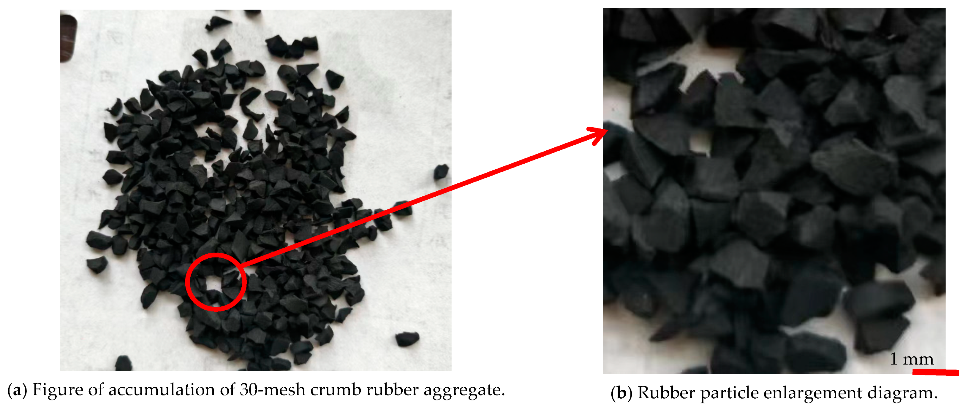
2.1. Material

This study used PO 42.5 ordinary Portland cement; its physical property index is summarized in Table 1. The specifications of the rubber granules were 30 mesh, with an average particle size of 420/μm, apparent density of 1240 kg/m3, sieve particle size of 620/μm, bulk density of 720 kg/m3, ash content of ≤8%, and a sieving rate of ≥95%. Figure 1 shows the crumb rubber aggregate used in the experiment. The fly ash dosage was 20% of the cement dosage; its performance is summarized in Table 2. We used coarse aggregate with a bulk density of 1550 kg/m3, 5–20 mm continuous gradation, an apparent density of 2870 kg/m3, a fine aggregate with ordinary river sand, a fineness modulus of 2.5, a particle size of 0–5 mm, an apparent density of 2640 kg/m3, and a bulk density of 1510 kg/m3. Polycarboxylate high-performance water reducer was used as an admixture, and the rate of water reduction was ≥25%. Normal tap water was used in the experiment.

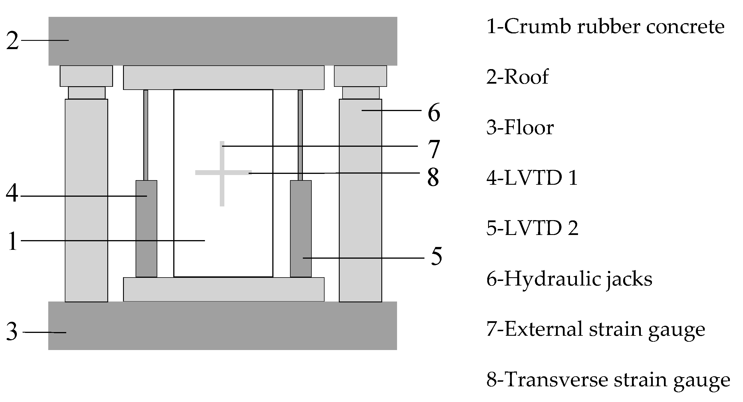
2.2. Experiment and Testing Methods

The concrete mixtures were prepared as described by JGJ 55-2011 [36], with a base water–binder ratio of 0.45. Thirty-mesh rubber particles were selected to prepare the rubber concrete by replacing natural sand at 5%, 10%, 15%, and 20% rates by equal volumes, respectively. The five concrete mixes designed in this study are shown in Table 3, which contains a group of ordinary concrete specimens, with three specimens in each group. Referring to GB/T50080-2016 [37], using HJW-60 concrete mixer, we performed the following stirring steps: first, the natural aggregate and cement were poured into the mixer and stirred evenly, then the rubber particles were added and the mixture was stirred until it was uniform. After that, we added approximately 70% of the water, followed by another 15–20 s of mixing. Finally, we added the admixture and remaining water and stirred for 2~3 min until the mixing was uniform. After the crumb rubber concrete solidified and formed, it was removed from the mold and left to cure for 28 days according to standard curing procedures. According to GB/T50081-2019 [38], the size of the uniaxial compression specimen was 150 × 150 × 300 mm.
The axial compression test of the prism was conducted using an electro-hydraulic servo press with two additional rigid components of 1000 kN hydraulic jacks. To enhance the integral rigidity of the testing equipment and prevent the sudden destruction of rubber concrete, the test device measured the descending portion of the crumb rubber concrete’s stress–strain curve. The specimen’s longitudinal displacement during axial compression was measured by two linear variable displacement transducers (LVDTs) on both sides, and the other two sides were pasted with concrete strain gauges at the vertical and horizontal geometric center lines to measure the horizontal and vertical strain of the crumb rubber concrete on the ascending portion of the stress–strain curve. Before the specimens reached 75% of the ultimate stress, the loading speed of the test device was 0.01 mm/s; after the stress of the specimens reached 75%, the loading speed was adjusted for 0.03 mm/s. The strain values were automatically collected using a DTS-530 high-speed static data acquisition instrument. A schematic of the experimental equipment is shown in Figure 2.

3. Energy Absorption of Crumb Rubber Concrete

The toughness of materials is usually determined based on their strength and ductility. Calculating the area under the uniaxial compression stress–strain curve reveals the related toughness of the material. The toughness of the material is determined from an energetic perspective by adding the pre-crack energy (PEC) before the crack, the absorbed energy during the crack, and the absorbed energy after the crack. The energy absorbed from the start of the test load to the yield point is known as the pre-cracking energy; this is acquired based on the area integral of the stress–strain curve between the origin and the yield point and the strain axis, as shown in the PEC section of Figure 3. Concrete’s characteristics differ from those of steel bars in that its yield stress and peak stress are closer together and its yield point is difficult to locate on the stress–strain curve. For this reason, Muhammad [39] researched a new method in which the yielding point is defined as the stress at the first crack on the specimen’s surface under uniaxial compression, and the crack energy absorbed by crumb rubber concrete during compression is defined as the integral area bounded by the stress–strain curve from the yielding point to peak point and strain axis, as shown in the CEC portion of Figure 3. We chose the stress corresponding to 80% after the stress–strain curve’s peak stress as the ultimate stress. The energy after the crack is the stress–strain curve’s integral area from the peak point to the ultimate stress and the strain axis, as shown in the PCEC section of Figure 3. The yellow part of Figure 3 shows the amount of energy that the concrete absorbed during uniaxial compression, including pre-crack energy, crack energy, and post-crack energy, defined as the sum of the three [39].

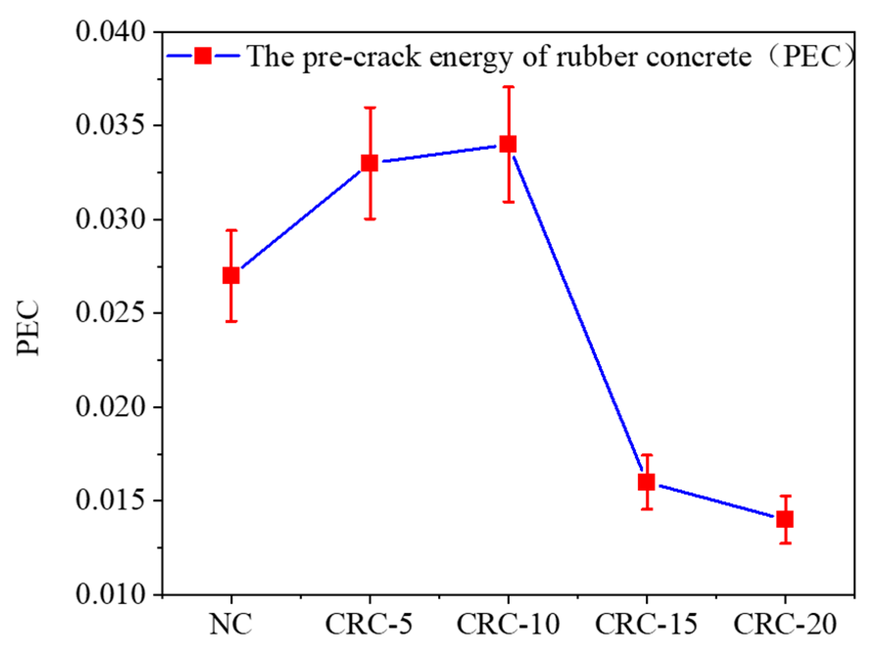
3.1. Pre-Crack Energy
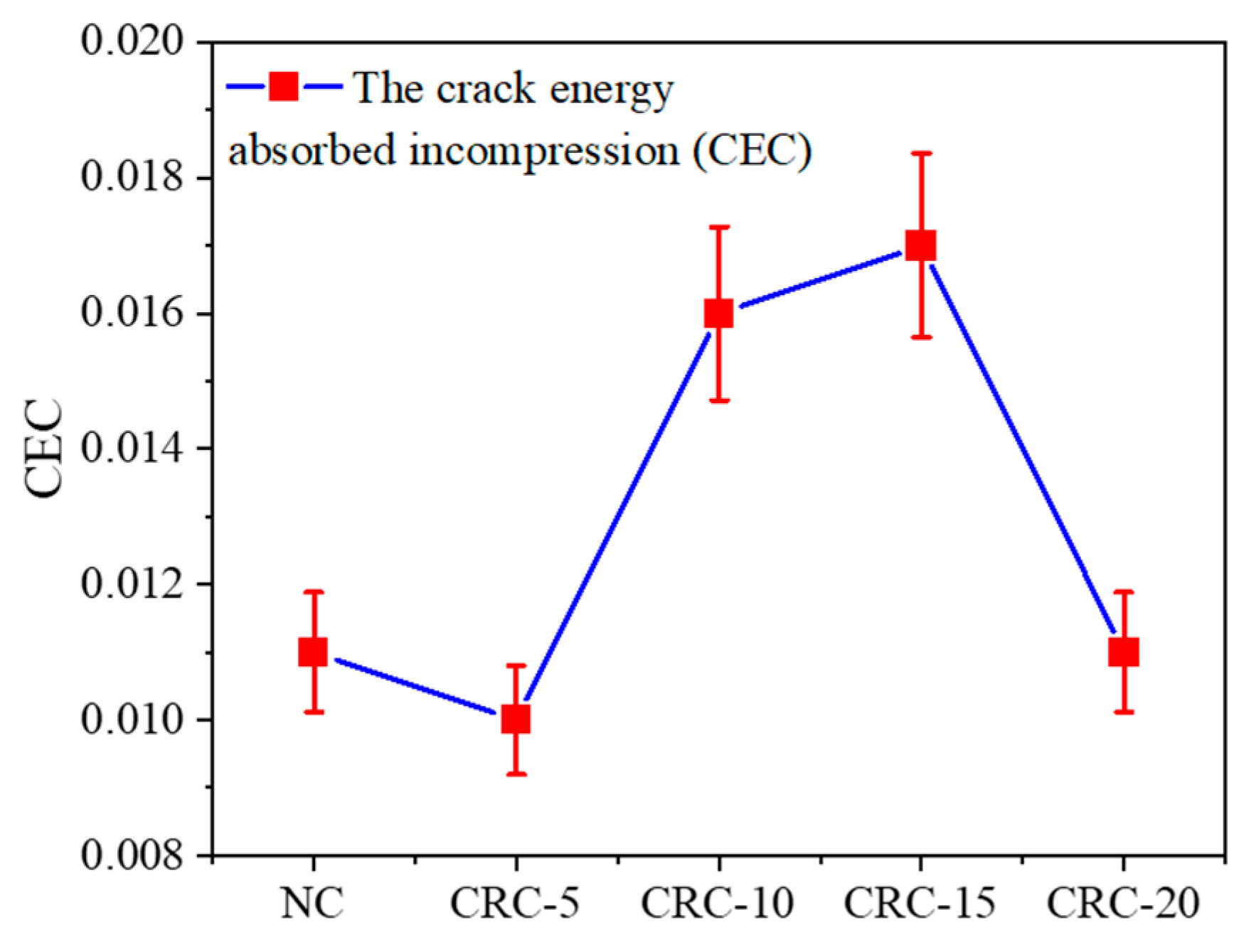
The pre-crack energy (PEC) value of the rubber concrete specimen is the energy absorbed to the yield point from the loading starting point. This is calculated by integrating the stress–strain curve’s area from the loading starting point to the yield point, as shown in Figure 4. The PEC value relies on the curve’s peak. Figure 4 shows that when the crumb rubber content increases, the PEC value increases and subsequently decreases, indicating that the crack resistance of the crumb rubber concrete also first increases and subsequently decreases when the crumb rubber content increases. At a 10% crumb rubber content, the PEC value reaches its maximum and is 26% greater than that of the regular concrete. The crumb rubber concrete absorbs the most energy and has the best anti-crack performance prior to the appearance of cracks when the rubber particle content reaches 10%. When the crumb rubber dosages are 15% and 20%, the PEC values are 40.7% and 48.1% less than that of regular concrete, respectively. The extensive use of crumb rubber is the primary factor in lowering the PEC value [40].

3.2. Crack Energy

The stress–strain curve’s integral area from the yield point to the peak is called the cracking energy of concrete (CEC). The time from the yield point to the peak value in concrete is very short, accounting for only 10–15% of the whole compression process [39]. Figure 5 compares the crack energy absorption behavior for various amounts of crumb rubber content. The change trend of the PEC value and the CEC value are practically identical; that is, when the content of crumb rubber increases, the CEC value first increases and subsequently decreases. When using 10% and 15% crumb rubber, respectively, the CEC value of the crumb rubber concrete was 45.5% and 54.5% greater than that of standard concrete; this shows that the energy absorption during crack development was significantly greater for the crumb rubber concrete compared to the standard concrete. When the crumb rubber concrete was damaged, the transition time was prolonged between the peak point and the yielding point, slowing the deterioration. The CEC value of 5% and 20% crumb rubber concrete does not significantly differ from that of ordinary concrete, indicating that the energy required for the development of cracks in crumb rubber concrete is similar to that of ordinary concrete at this dosing level.

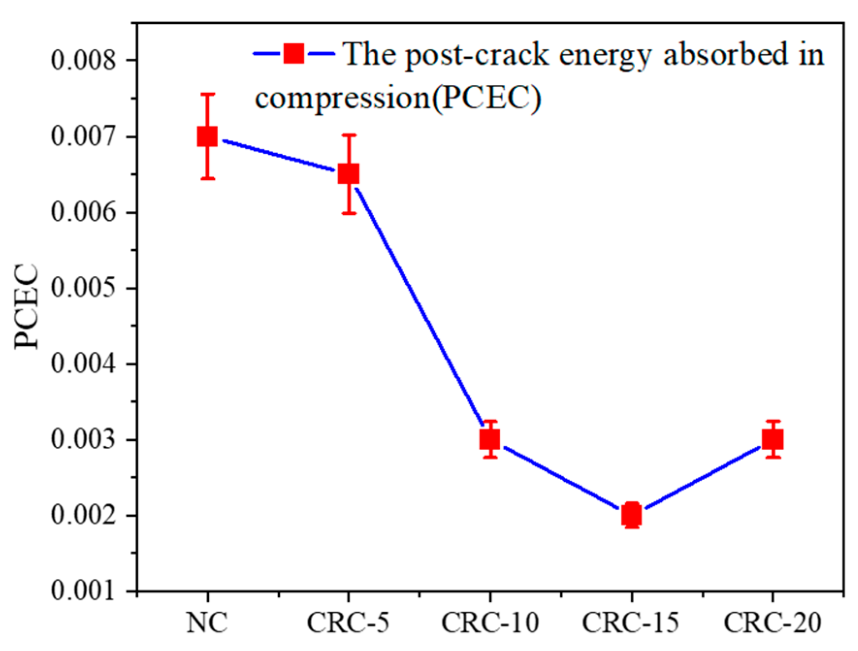
3.3. Post-Crack Energy Absorbed in Compression

The post-crack energy absorbed during the compression (PCEC) of the concrete specimens is the integral area enclosed by the stress–strain curve from the peak stress point to the ultimate stress point and strain axis, and the ultimate stress is defined as the stress corresponding to a 20% decrease in the peak stress on the stress–strain decrease section. The energy absorption capacity of each specimen after the peak point is displayed in Figure 6. This figure indicates that as the rubber dosage is increased, the PCPE value of the rubber concrete essentially continues to decrease, and when the dosage of rubber is 5%, the rubber concrete’s energy dissipation capacity does not change significantly, the brittleness does not change significantly compared with ordinary concrete, and the PCEC value only decreases by 7.1%. When the dosage of rubber particles exceeds 5%, the PCPE value decreases sharply. The PCPE value is reduced to the lowest when the rubber dosage is 15%, which is 71.4% lower compared with ordinary concrete. At this time, the crumb rubber concrete’s energy dissipation capacity decreases sharply, the brittleness increases significantly, and it is rapidly crushed after reaching the peak stress.

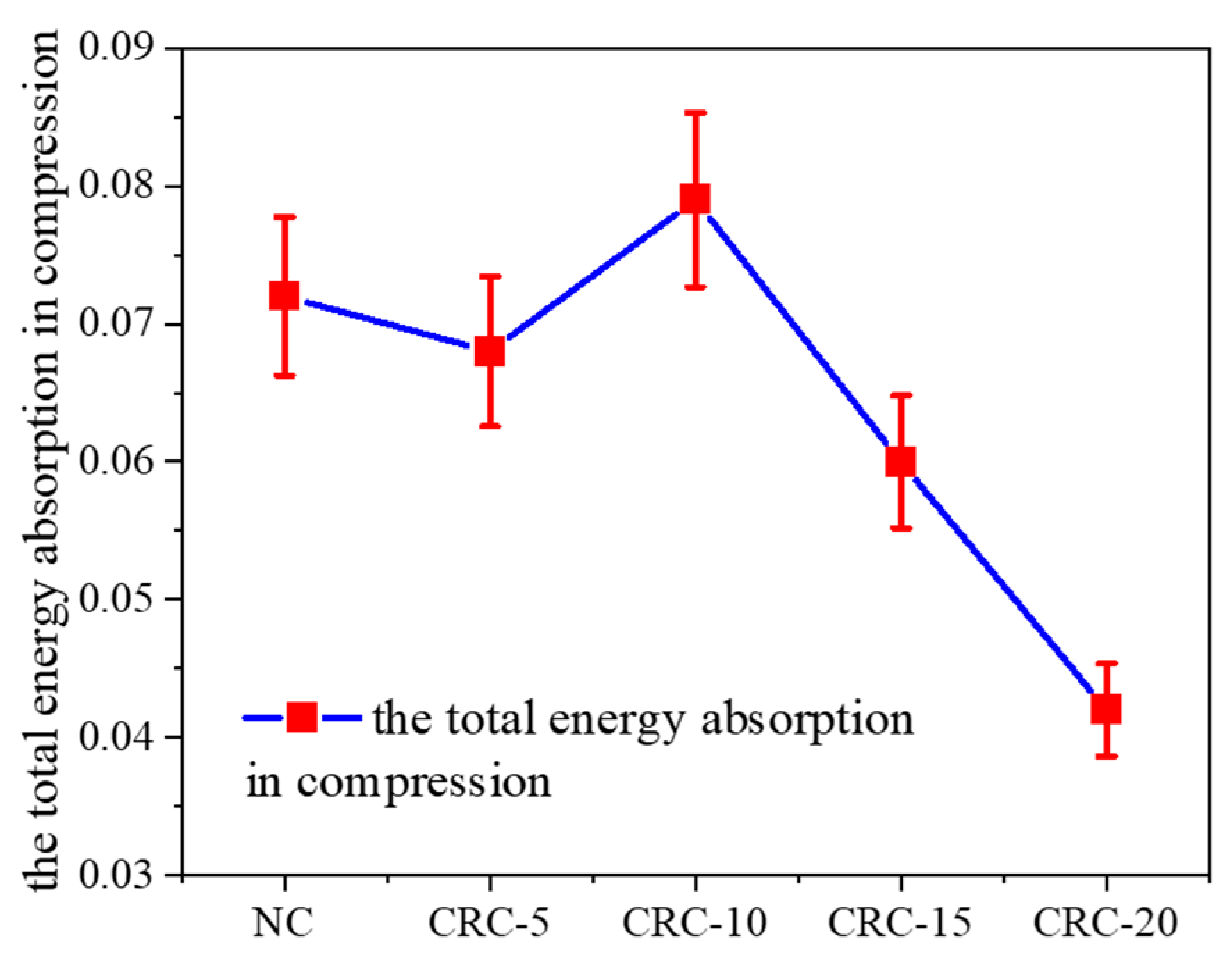
3.4. Total Energy Absorption during Compression

The area from the starting point to the end point of the stress–strain curve can be used to characterize the energy absorbed by rubber concrete from the beginning of loading to complete destruction, which is related to the toughness and strength of the crumb rubber concrete. Figure 7 illustrates the energy absorbed during the destruction of rubber concrete. When the rubber particle dose is increased, the total energy absorbed during the entire destruction process of the rubber concrete initially increases before falling again. When the rubber dosage is 10%, the total energy absorbed reaches the maximum. This is largely because it is difficult to observe the rubber particles weakening the strength of concrete when the rubber content is minimal, indicating that the addition of crumb rubber enhances the toughness of concrete. As a result of the low crumb rubber dosage, crumb rubber concrete has a slightly higher energy absorption capacity than regular concrete. A large dosage of rubber particles significantly weakens concrete. The improvement in the concrete’s toughness is not sufficient to compensate for its reduction in strength, and as such, it shows a significant decrease in its energy absorption capacity [41]. In Figure 7, the rubber concrete absorbs 69.4% more energy than the ordinary concrete when the rubber dosage is 10%. The total energy absorbed by the rubber concrete is lowered by 41.7% with a rubber dosage of 20% compared to the ordinary concrete.

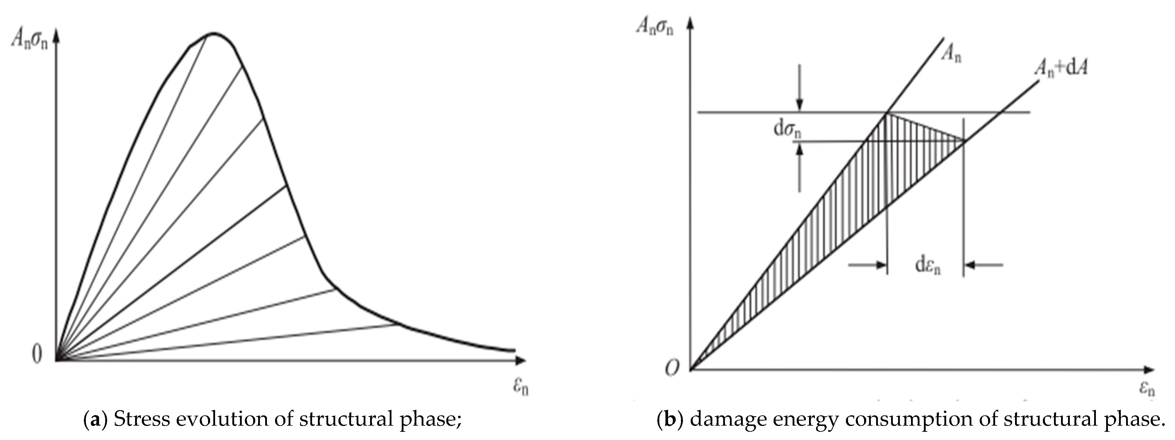
4. Establishing the Damage Model Based on the Energy Method

4.1. Establishment of the Damage Model

In references [42,43], the statistical method of calculating damage microelements before and after the introduction of the damage threshold was used to establish the concrete damage constitutive model, which revealed that the theoretical basis of the statistical method is insufficient [44,45]. In this study, by applying the basic law of irreversible thermodynamics and the principle of energy balance, the uniaxial compression damage process of crumb rubber concrete is regarded as a transition from the structural phase to the damage phase, and the damage model and damage evolution law of crumb rubber concrete are analyzed [46].
From the point of view of energy conversion, damage is the conversion of structural phase deformation energy to damage evolution energy consumption [46]. Figure 7 shows the damage energy consumption evolution curve. Meanwhile, Figure 8a shows that as the stress increases, the structural phase’s area decreases, with a subsequent reduction in the structural phase’s bearing capacity. Figure 8b shows that when the stress and strain increase d σ n and d ε n , respectively, the damage phase increases d A d , while the structural phase decreases d A d accordingly, and the energy consumed by the damage is Ω .
d Ω = A n 1 2 σ n d ε n
From the viewpoint of irreversible thermodynamics, the energy consumed when the structural phase progresses into the damaging phase is a reflection of the continuous development process of microcracks in the structural phase of rubber concrete, so the structural phase’s damage results in energy consumption [46]. As the damage phase’s area grows, d A d , the energy dissipation can be represented as follows:
d Ω = d Ω d A d d A d = Ω d A d
The formulation of the damage variable D from a damage mechanics viewpoint is:
D = A d A = A d A n
According to Equation (2), we should rewrite Equation (3) as:
d D = 1 2 Ω ( 1 D ) σ n d ε n
The evolution of the damage variable D is shown in Equation (4), which has a clear physical meaning. In uniaxial compression, the damage energy consumption is proportional to the ease of damage development, and it is easier to develop a damage phase when the structural phase’s stress A is larger. The rubber concrete damage evolution law can be expressed by Equation (4), which can be rewritten as follows:
d D 1 D = 1 2 Ω   σ n d ε n
Introducing the damage threshold k for analysis and integrating Equation (5), the damage variable D can be expressed as:
D = { 0 ε k 1 exp ( 1 2 Ω σ n d ε n ) ε k
From the perspective of the elastic–plastic strain principle, the strain ε of the concrete be subdivided into the elastic strain and plastic strain, ε p . Thus, when the plastic strain is considered, the damage constitutive equation for rubber concrete is:
σ = E 0 ( 1 D ) ( ε ε P )
Under the triaxial stress state, substituting Equation (6) into Equation (7) yields the damage constitutive equation:
σ = { E 0 ( ε 1 ε P ) + μ ( σ 2 + σ 3 ) ε k E 0 ( ε 1 ε P ) exp ( 1 2 Ω σ n d ε n ) + μ ( σ 2 + σ 3 ) ε k
When the system composed of different components is subjected to external forces, the dynamic evolution process of its traits and internal structure can be reflected in the susceptible–infective–removal (SIR) model and the Guo Zhenhai model. Therefore, these two models can describe the damage process of crumb rubber concrete undergoing uniaxial compression. The expression of the SIR model is:
y = c ( e b x e a x )
In the equations x = ε / ε c , y = σ / f c , the formula using the energy method for the SIR damage variable representation is obtained by substituting Equation (9) into Equation (6) in the case of uniaxial compression.
D = { 0 ε k 1 exp [ 1 2 Ω 0 ε c c ( e b ε ε c e a ε ε c ) f c d ε ] ε k
By substituting Equation (10) into Equation (7), an energy method-based SIR damage constitutive model of crumb rubber concrete can be obtained. The expression is as follows:
σ = { 0 ε k E 0 ( ε ε P ) exp [ 1 2 Ω 0 ε c c ( e b ε ε c e a ε ε c ) f c d ε ] ε k
In the equation, a / ε c , b / ε c , and c f c are constants, defining them as a 1 , b 1 , and c 1 , respectively.
When the damage threshold k of rubber concrete is obtained, using the energy method, the SIR damage model for rubber concrete can be produced according to the peak stress f c and plastic strain ε p of the stress–strain curve. Figure 9 shows the experimental curve of the CRC-15 group and the theoretical curve derived from multiple damage thresholds. As shown in the diagram, when the damage threshold k is 0.2, the theoretical curve is similar to the experimental curve, and the degree of agreement is the highest. Therefore, k = 0.2 is taken as the optimal damage threshold of the CRC-15 group, represented by k . Similarly, the optimal damage threshold of the other groups of rubber concrete can be determined, and the theoretical damage model of the rubber concrete under the optimal damage threshold with the corresponding ratio can be derived.
The constitutive relation expression of concrete under uniaxial compression proposed by Guo Zhenhai is in segmental form, with the peak stress point defined as the boundary, divided into rising and falling segments. The rising segment is defined as a polynomial function, and the falling segment is defined as a rational fractional function. Its expression is as follows:
y = { A x + ( 3 2 A ) x 2 + ( A 2 ) x 3 0 x 1 x B ( x 1 ) 2 + x
In the equation, y = σ / f c , σ is the stress, f c is the peak stress; ε is the strain, and ε c is the peak strain.
Using the constitutive model of Guo Zhenhai (Equation (12)), using the energy method, an equation for the damage variable can be derived:
D = { 0 0 ε k 1 exp [ 1 2 Ω ( 1 2 A ε c 2 ε 2 + 1 3 3 2 A ε c 3 ε 3 + 1 4 A 2 ε c 4 ε 4 ) ] k ε ε c 1 exp [ 1 2 Ω ( 1 12 A ε c + 1 2 ε c ) 1 2 Ω ε c ε ε ε c B ε 2 ( 2 B 1 ) ε ε c + B ε c d ε ] ε ε c
Using the energy method, the damage model for the crumb rubber concrete can be derived by inserting Equation (13) into Equation (7).
σ = { E 0 ( ε 1 ε p ) + μ ( σ 2 + σ 3 ) ε k E 0 ( ε 1 ε p ) exp [ 1 2 Ω ( 1 2 A ε c 2 ε 2 + 1 3 3 2 A ε c 3 ε 2 + 1 4 A 2 ε c 4 ε 4 ) ] k ε ε c E 0 ( ε 1 ε p ) exp [ 1 2 Ω ( 1 12 A ε c + 1 2 ε c ) 1 2 Ω ( ε ε c B ε 2 ( 2 B 1 ) ε ε c + B ε c ) ] ε ε c
The determination method for the k value in Equation (14) is consistent with that in Equation (11).
According to Equations (11) and (14), the SIR and Guo Zhenhai damage models based on the energy method for crumb rubber concrete can be calculated, respectively. Figure 10 compares the two damage models and the test results. As seen in Figure 10, the rising section of the test curve of the crumb rubber concrete is in good agreement with the two damage models, indicating that the two damage models can satisfactorily express the rising section of the test curve of the crumb rubber content. However, the damage model is in good agreement with the descending section of the test curve only when using the energy method. Therefore, this study employed the Guo Zhenhai damage model based on the energy method to describe the stress–strain curve of the crumb rubber concrete.

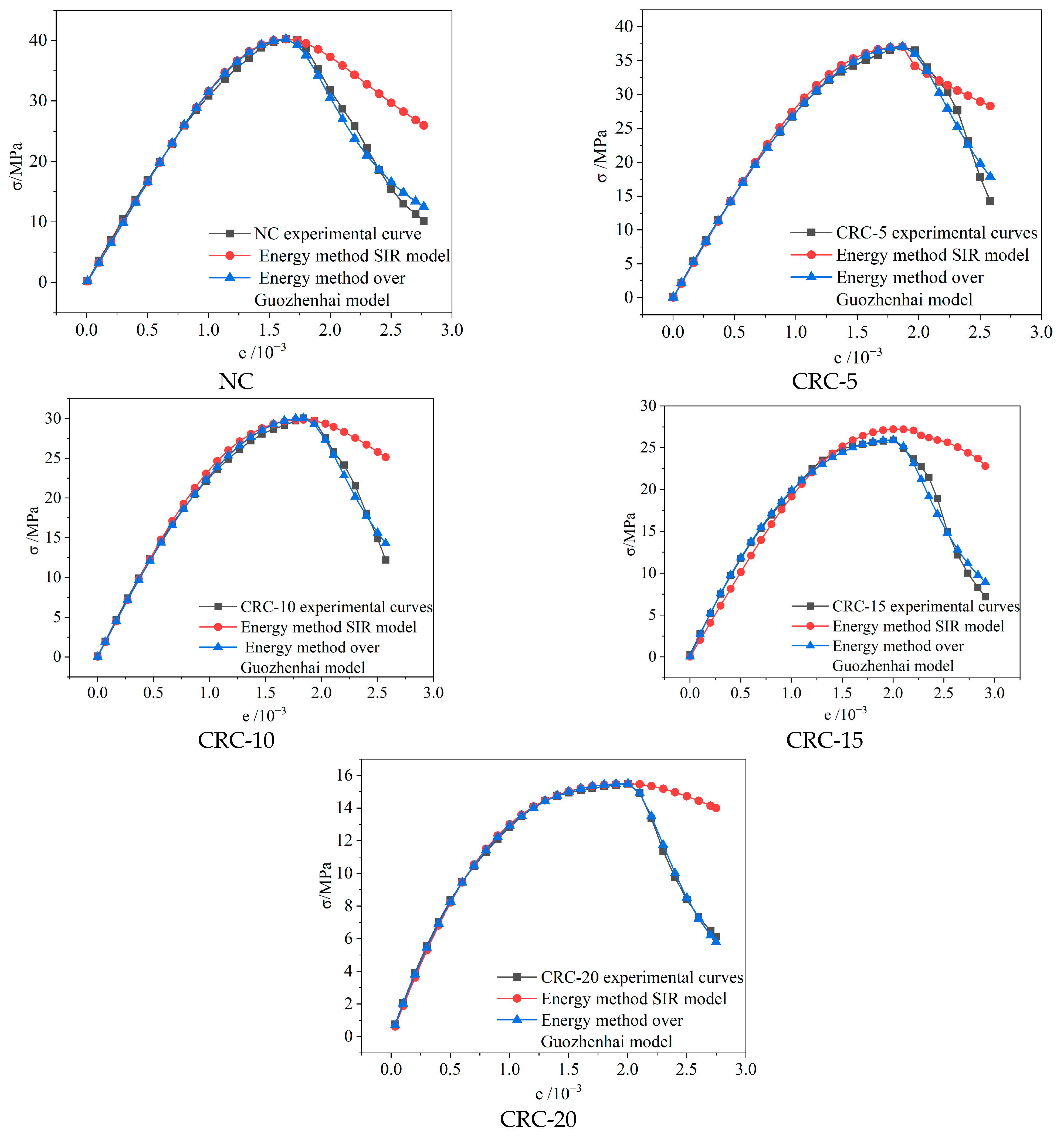
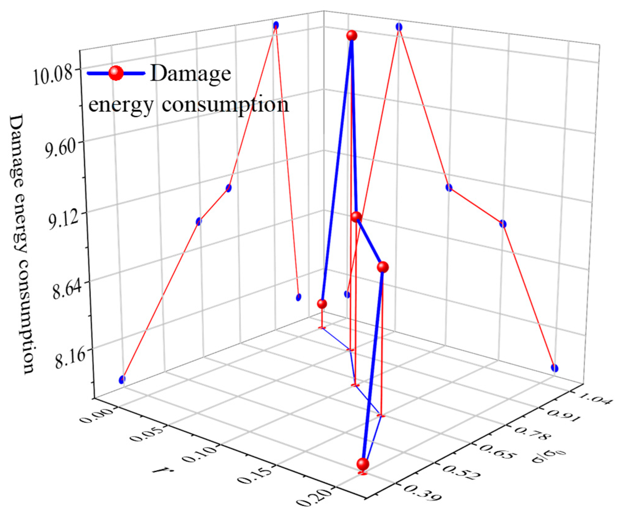
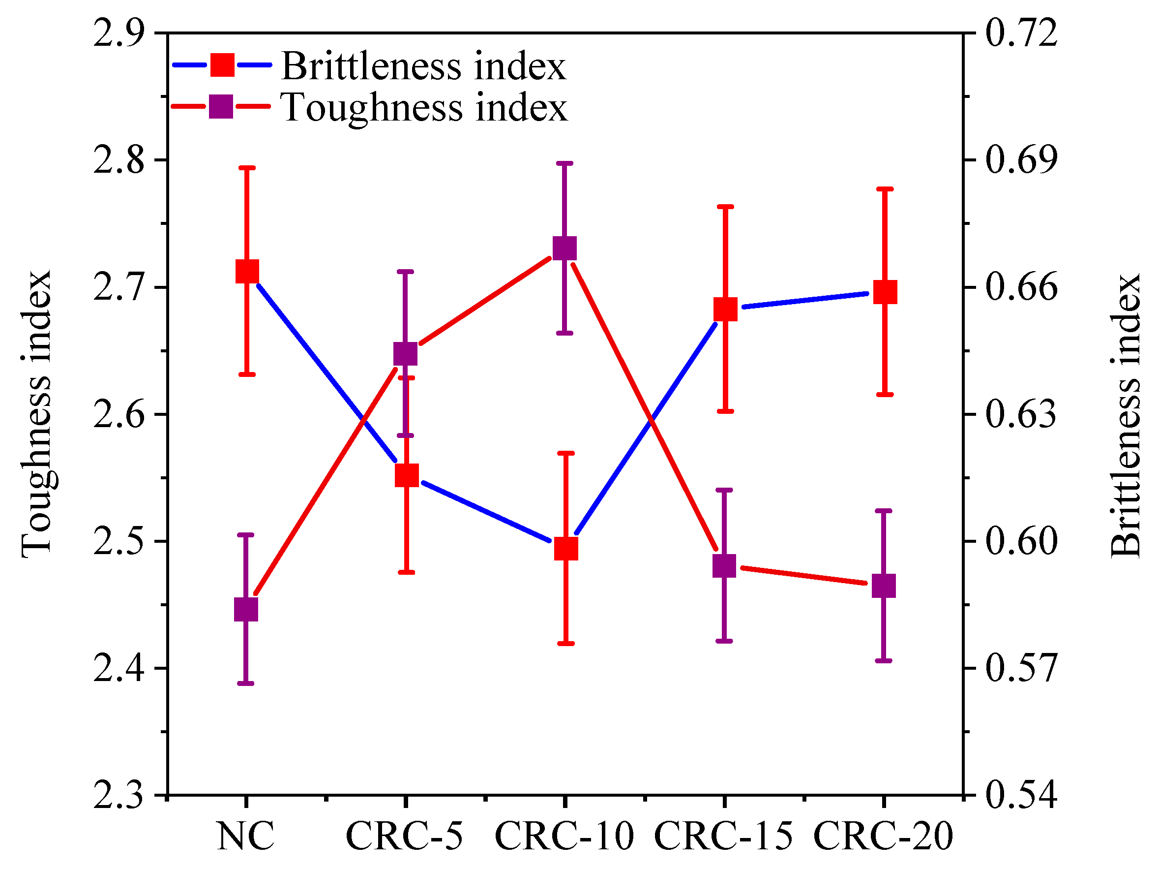
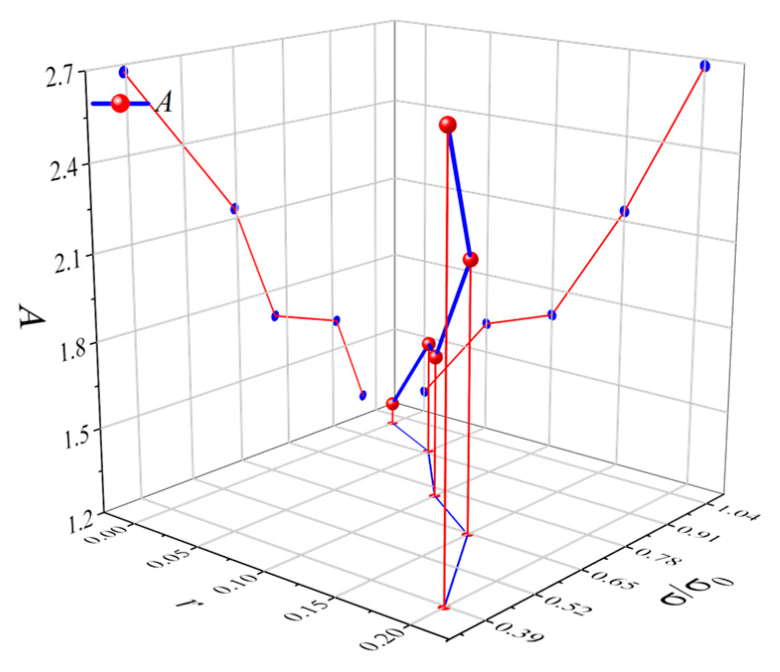
4.2. Analysis of Model Parameters

The test curve in this study is expressed by the damage model built by Guo Zhenhai based on the energy method. The material properties and the loading method are determined based on the damage threshold k of the model, and the starting point of the plastic damage due to the uniaxial compression of the specimen is defined as the damage threshold, which is expressed as the strain to peak strain ratio at the onset of the plastic damage. The method used to determine the optimal damage threshold k is discussed in Section 4.1 of this paper. Table 4 shows the optimal damage threshold k of the damage model built by Guo Zhenhai based on the energy method, and its changes with the dimensionless stress σ / σ 0 and rubber content r are exhibited in Figure 11. Figure 11 indicates that as the crumb rubber content increases, the damage threshold decreases, indicating that incorporating crumb rubber will lead to more rapid deformation of concrete before it reaches the plastic stage. Figure 12 (1000× zoomed in) shows a scanning electron microscope image of the interfacial transition zone (ITZ) between the rubber particles, natural sand, and cement matrix, where the poor bonding performance between the rubber particles and cement matrix [2,47] only allows the rubber concrete to maintain linear elasticity for a short time.
According to Figure 11, the relationship between the dimensionless stress σ / σ 0 , the rubber dosage r, and the optimal damage threshold k can be fitted, as shown in Equation (15). The determination coefficient is greater than 0.98. According to Equation (15), the optimal damage threshold k can be calculated, as shown in Table 4; the difference between k and k is small, and Equation (15) can be used to calculate the optimal damage threshold to determine the strain state of the rubber concrete corresponding to plastic deformation.
k = 0.025 σ σ 0 2.676 r + 0.646
In the equation, σ = σ pk , and d σ d ε = 0 is the ordinary concrete’s peak stress.
Based on the full stress–strain curve, the following geometric boundary conditions are identified: (1) ε = 0 , σ = 0 ; (2): ε = 0 , d σ d ε = E ; (3): σ = σ pk , ε = ε pk ; (4): σ = σ pk , d σ d ε = 0 .
The calculation expression of the damage energy dissipation is shown in Equation (16), which is obtained by substituting Equation (11) into the above four boundary conditions. The results of the damage energy dissipation calculated using Equation (16) are listed in Table 5. Reference [46] states that when the damage energy dissipation Ω increases, the peak stress σ p k gradually increases and the peak strain gradually decreases, which leads to an increase in the concrete’s strength and brittleness. Figure 13 shows the changes in the damage energy dissipation Ω with the crumb rubber dosage r and dimensionless stress σ / σ 0 . The fitting function appears in Equation (17).
As the crumb rubber content of the concrete increases, the damaging energy consumption gradually decreases, as shown in Figure 13. The brittleness index and toughness index of the rubber concrete in Figure 14 demonstrate that the inclusion of crumb rubber increases the concrete’s toughness. The conclusion of the ductility of crumb rubber concrete obtained in this study is consistent with the conclusion presented in reference [46]. However, the conclusion obtained in this study contradicts that of reference [46]. It was determined that the concrete contains more coarse aggregate, and the crumb rubber and coarse aggregate have a poor bonding ability, which eventually leads to a decrease in the concrete’s strength [48,49].
Ω = c 1 ( e b 1 ε c e a 1 ε c ) ( b 1 e b 1 ε c a 1 e a 1 ε c ) 2 ε c
Ω = 33.33 σ σ 0 + 100 r 26
The parameter calculation results of the energy method-based damage model built by Guo Zhenhai are exhibited in Table 5. In order to facilitate its application, the function of the parameters with the rubber content and the dimensionless stress is obtained, as shown in Equations (18) and (19). The changes in parameters A and B with crumb rubber r and dimensionless stress σ / σ 0 are exhibited in Figure 15 and Figure 16, respectively. Parameter A characterizes the curve of the rising section of the damage model. The larger the A value, the higher the ratio of the tangent modulus of the origin to the peak secant modulus, and the better the ductility of the material [50]. The ductility of the crumb rubber concrete rises as the crumb rubber content increases, as shown in Table 5.
A = 1.55 σ σ 0 + 1.99 r + 2.83
B = 7.91 σ σ 0 + 18.21 r + 15.58
The Guo Zhenhai damage model of crumb rubber based on the energy method is shown in Equation (20), and the findings of the above analysis show that the model is both reasonable and practical.
σ = { E 0 ( ε 1 ε p ) + μ ( σ 2 + σ 3 ) ε k E 0 ( ε 1 ε p ) exp [ 1 2 Ω ( 1 2 A ε c 2 ε 2 + 1 3 3 2 A ε c 3 ε 3 + 1 4 A 2 ε c 4 ε 4 ) ] k ε ε c E 0 ( ε 1 ε p ) exp [ 1 2 Ω ( 1 12 A ε c + 1 2 ε c ) 1 2 Ω ( ε ε c B ε 2 + ( 2 B 1 ) ε ε c + B ε c ) ] ε ε c
The parameters k and Ω in the equation are obtained according to Equation (15) and Equation (17), respectively. According to Equations (18) and (19), parameters A and B are determined.

5. Damage Evolution Law of Crumb Rubber Concrete

Two types of D ε curves for rubber concrete based on the energy-based method can be calculated using the energy-based method damage variable calculation Equations (10) and (12), as exhibited in Figure 16. Furthermore, the damage evolution of crumb rubber concrete is analyzed throughout the uniaxial compression damage process.
Using the first-order derivative function of the damage variable concerning the strain ε , during the uniaxial compression process, a change in the damage development rate based on the energy method can be analyzed. The derivative of the damage variable is shown in Equations (21) and (22).
d D d ε = { 0 ε k 1 2 Ω cf c ( e b ε ε c e a ε ε c ) exp   [ 1 2 Ω 0 ε c c ( e b ε ε c e a ε ε c ) f c d ε ] ε k
d D d ε = { 0 ε k 1 2 Ω ( A ε c 2 ε + 3 2 A ε c 3 ε 2 + A 2 ε c 4 ε 3 ) exp [ 1 2 Ω ( 1 2 A ε c 2 ε 2 + 1 3 3 2 A ε c 3 ε 2 + 1 4 A 2 ε c 4 ε 4 ) ] k ε ε c 1 2 Ω [ ε ε c B ε 2 ( 2 B 1 ) ε ε c + B ε c ] exp [ 1 2 Ω ( 1 12 A ε c + 1 2 ε c ) 1 2 Ω ( ε ε c B ε 2 ( 2 B 1 ) ε ε c + B ε c ) ] ε ε c
Figure 17 shows that the D ε curves derived from the two constitutive models based on the energy method are similar; both of them exhibit a monotonic growth of the “S” type with increasing strain. The energy method does not consider the initial damage that crumb rubber causes in concrete, so the amount of damage for each group calculated based on the energy method gradually increases from zero. Compared with ordinary concrete, rubber concrete has a lower maximum damage development rate, indicating a more moderate damage process for crumb rubber concrete. During the initial loading phase, the two sets of D ε curves shown in Figure 16 show that the CRC-20 group’s damage variable D ε is significantly larger than that of other groups at the same strain level. This mostly results from the large dosage of crumb rubber. In addition, Figure 18 shows that the damage development rate of the CRC-20 group is also significantly greater than that of the other groups at the beginning of the loading phase. The development and change in the two damage development rates shown in Figure 18 show that the NC group has the best maximum damage development rate. In the initial loading phase, compared with the ordinary concrete, the rubber concrete has a higher damage development rate; the crumb rubber concrete has a lower damage development rate than the ordinary concrete during the plastic strain stage.

6. Discussion

The above research methods further resolve the drawbacks of using the traditional concrete constitutive model to fit a variety of modern concrete constitutive relations. By changing the model parameters of the traditional constitutive model to describe the constitutive relationships between a variety of modern concretes, even if a high degree of fitting is achieved, the description of many feature points is often not accurate enough, such as elastic deformation process, peak stress, peak strain, ultimate stress, ultimate strain, plastic deformation process, and so on. In this study, the damage constitutive model and damage evolution law of rubber concrete are analyzed using the basic law of irreversible thermodynamics and the principle of energy balance. The damage evolution of rubber concrete is regarded as the process of transformation from the structural phase to the damage phase. The whole process of compression damage of rubber concrete is described in detail, which can express the damage model of rubber concrete more accurately. By studying the functional relationship between the rubber content, mechanical properties, and model parameters, the damage constitutive model of rubber concrete can be derived more directly and conveniently in practical engineering applications.
Many scholars have studied the damage evolution law of rubber concrete using acoustic emission or numerical simulations. In this study, the damage variable expression in the process of the rubber concrete damage model is derived to calculate the damage amount of rubber concrete under uniaxial compression, which is an innovation in the research method.
In theory, the incorporation of rubber particles reduces the stiffness of concrete. In fact, not only the stiffness is reduced, but also the strength and other indicators. Therefore, rubber concrete should be used when the indexes such as stiffness and strength meet the specifications.

7. Conclusions

This paper analyzes the energy absorption capability of crumb rubber concrete during uniaxial stress. After investigating the SIR damage model and the Guo Zhenhai damage model based on the energy method, we obtained the following results:
  • With the increase in rubber particle dosage, the pre-cracking energy, cracking energy, and total energy absorbed by the rubber concrete increase and then decrease, while the energy absorption capacity after cracking gradually decreases. The changing trend in the total energy absorption during the compression of the crumb rubber concrete is consistent with the changing trend in the damage dissipation energy Ω .
  • The Guo Zhenhai damage model based on the energy method more accurately describes the entire stress–strain curve of the crumb rubber concrete, and the brittleness characteristics of the model parameters and brittleness index remain consistent.
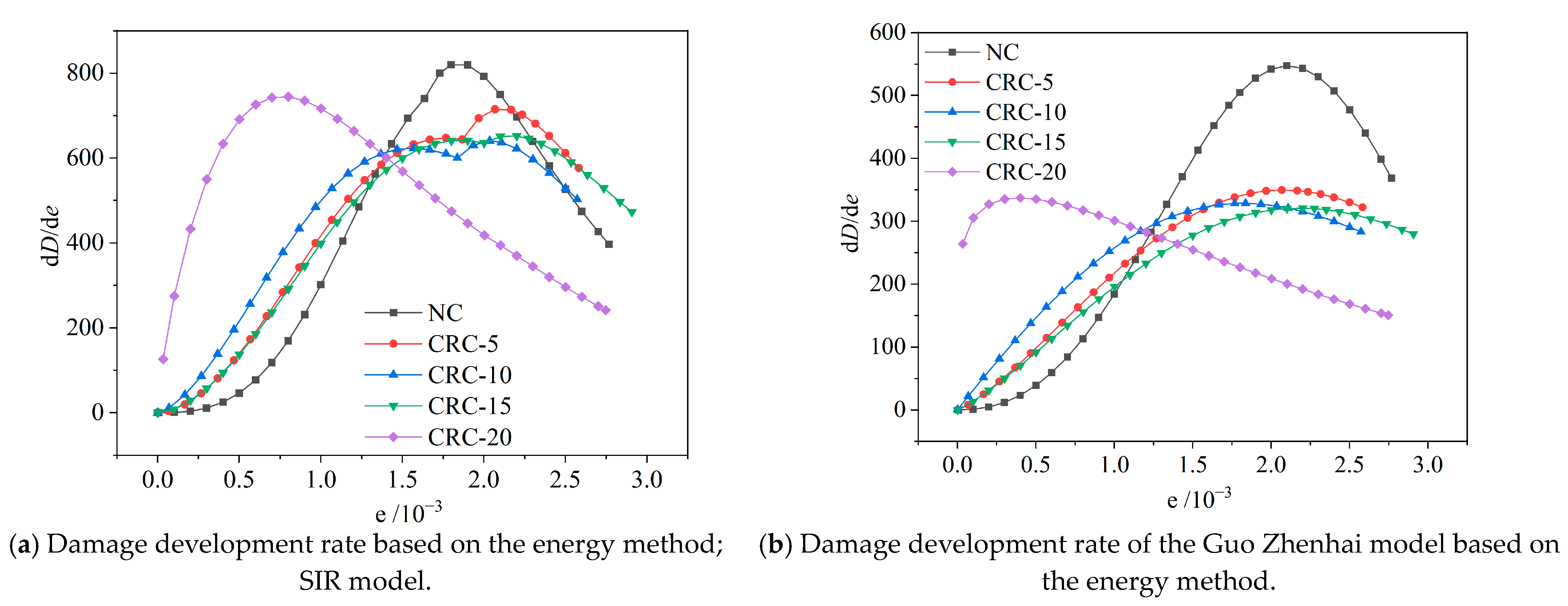
  • There are similarities between the two rubber concrete damage evolution patterns based on the energy method, and both sets of D ε curves monotonically increase from 0 in an “S” shape. When the strain reaches the plastic strain stage, the damage development rate of ordinary concrete exceeds that of rubber concrete, and the maximum damage development rate is higher than that of crumb rubber concrete.

Author Contributions

T.G.: writing—original draft, investigation, software, methodology. G.X.: funding acquisition, project administration, methodology. B.F.: methodology, conceptualization. All authors have read and agreed to the published version of the manuscript.

Funding

This work was supported by the National Natural Science Foundation of China (Project No. 52168032).

Data Availability Statement

Data will be made available upon request. The data are not publicly available due to privacy concerns.

Conflicts of Interest

The authors declare no conflicts of interest.

References

  1. Lin, Q.; Liu, Z.; Yu, L.; Zhou, Y.; Cui, Y. Mechanical properties of emulsified asphalt rubber concrete. Acta Mater. Compos. Sin. 2023, 40, 1560–1568. [Google Scholar]
  2. Lin, Q.; Liu, Z.Q.; Sun, J.L.; Yu, L. Comprehensive modification of emulsified asphalt on improving mechanical properties of crumb rubber concrete. Constr. Build. Mater. 2023, 369, 12. [Google Scholar] [CrossRef]
  3. Ren, F.M.; Mo, J.X.; Wang, Q.; Ho, J.C.M. Crumb rubber as partial replacement for fine aggregate in concrete: An overview. Constr. Build. Mater. 2022, 343, 24. [Google Scholar] [CrossRef]
  4. Su, T.; Wang, T.; Zhang, Z.; Sun, X.; Gong, S.; Mei, X.; Tan, Z.; Cui, S. Mechanical properties and frost resistance of recycled brick aggregate concrete modified by nano-SiO2. Nanotechnol. Rev. 2023, 12, 20230576. [Google Scholar] [CrossRef]
  5. Xue, G.; Fu, Q.; Xu, S.; Li, J.J. Macroscopic mechanical properties and microstructure characteristics of steel slag fine aggregate concrete. J. Build. Eng. 2022, 56, 17. [Google Scholar] [CrossRef]
  6. Benazzouk, A.; Murzeb, K.; Doyen, G.; Goullieux, A.; Quéneudec, M. Effect of rubber aggregates on the physico-mechanical behaviour of cement-rubber composites-influence of the alveolar texture of rubber aggregates. Cem. Concr. Compos. 2003, 25, 711–720. [Google Scholar] [CrossRef]
  7. Asgharzadeh, S.M.; Sadeghi, J.; Peivast, P.; Pedram, M. Fatigue properties of crumb rubber asphalt mixtures used in railways. Constr. Build. Mater. 2018, 184, 248–257. [Google Scholar] [CrossRef]
  8. Ling, T.C. Effects of compaction method and rubber content on the properties of concrete paving blocks. Constr. Build. Mater. 2012, 28, 164–175. [Google Scholar] [CrossRef]
  9. Ouyang, X.; Wu, Z.M.; Shan, B.; Chen, Q.; Shi, C.J. A critical review on compressive behavior and empirical constitutive models of concrete. Constr. Build. Mater. 2022, 323, 21. [Google Scholar] [CrossRef]
  10. He, J.R.; Gao, R.F.; Tang, Z.Y. A data-driven multi-scale constitutive model of concrete material based on polynomial chaos expansion and stochastic damage model. Constr. Build. Mater. 2022, 334, 15. [Google Scholar] [CrossRef]
  11. Li, D.D.; Yan, Z.G.; Gravina, R.; Mills, J.E. Compressive stress strain behavior of crumb rubber concrete (CRC) and application in reinforced CRC slab. Constr. Build. Mater. 2018, 166, 745–759. [Google Scholar] [CrossRef]
  12. Elzeadani, M.; Bompa, D.V.; Elghazouli, A.Y. Experimental assessment and constitutive modelling of rubberised One-Part Alkali-Activated concrete. Constr. Build. Mater. 2022, 353, 27. [Google Scholar] [CrossRef]
  13. Zhang, Y.; Zhang, S.Q.; Zhao, W.G.; Jiang, X.; Chen, Y.B.; Hou, J.X.; Wang, Y.C.; Yan, Z.G.; Zhu, H.H. Influence of multi-scale fiber on residual compressive properties of a novel rubberized concrete subjected to elevated temperatures. J. Build. Eng. 2023, 65, 20. [Google Scholar] [CrossRef]
  14. Dong, S.; Zhao, Q.H.; Zhu, H. Mechanical properties and constitutive model of steel fiber-reinforced rubberized concrete. Constr. Build. Mater. 2022, 327, 21. [Google Scholar] [CrossRef]
  15. GB50010-2010; Code for Design of Concrete Structures. National Standards of the People’s Republic of China: Beijing, China, 2010.
  16. Abbara, A.A.; Abdelhalim, A.; Al-Ajamee, M.; Ahmed, O.; Adhikary, S.K.; Ahmed, M. Uniaxial compressive stress-strain relationship for rubberized concrete with coarse aggregate replacem ent up to 100%. Case Stud. Constr. Mater. 2022, 17, e01336. [Google Scholar] [CrossRef]
  17. Bompa, D.V.; Elghazouli, A.Y.; Xu, B.; Stafford, P.J.; Ruiz-Teran, A.M. Experimental assessment and constitutive modelling of rubberised concrete materials. Constr. Build. Mater. 2017, 137, 246–260. [Google Scholar] [CrossRef]
  18. Li, L.J.; Ruan, S.H.; Zeng, L. Mechanical properties and constitutive equations of concrete containing a low volume of tire rubber particles. Constr. Build. Mater. 2014, 70, 291–308. [Google Scholar] [CrossRef]
  19. Pan, D.P. Constitutive Research of Crumb Rubber Concrete. Master’s Thesis, Guangdong University of Technology, Guangzhou, China, 2006. [Google Scholar]
  20. Cui, X.S.; Guo, Q.; Wu, H. Analysis of Damage of Rubber Concrete in Freezing-thawing Circumstance. Chongqing Jiaotong Univ. 2018, 37, 40–45. [Google Scholar] [CrossRef]
  21. Zhu, X.B.; Miao, C.W.; Liu, J.P.; Hong, J.X. Influence of crumb rubber on frost resistance of concrete and effect mechanism. Procedia Eng. 2012, 27, 206–213. [Google Scholar] [CrossRef]
  22. Wen, J.; Su, Y.W. Frost resistance and damage degradation model of polypropylene fiber rubber concrete. New Build. Mater. 2022, 49, 54–59. [Google Scholar]
  23. Gonen, T. Freezing-thawing and impact resistance of concretes containing waste crumb rubbers. Constr. Build. Mater. 2018, 177, 436–442. [Google Scholar] [CrossRef]
  24. Zhu, R.N.; Pang, J.Y.; Wang, T.Y. Effect of chloride erosionon mechanical properties damage of rubber concrete. Mine Constr. Technol. 2020, 41, 21–25. [Google Scholar] [CrossRef]
  25. Xu, J.; Niu, X.L.; Yao, Z.Y. Mechanical properties and acoustic emission data analyses of crumb rubber concrete under biaxial compression stress states. Constr. Build. Mater. 2021, 298, 15. [Google Scholar] [CrossRef]
  26. Xu, J.; Shu, S.R.; Han, Q.H.; Liu, C. Experimental research on bond behavior of reinforced recycled aggregate concrete based on the acoustic emission technique. Constr. Build. Mater. 2018, 191, 1230–1241. [Google Scholar] [CrossRef]
  27. Xu, J.; Houndehou, J.D.; Wang, Z.Y.; Ma, Q. Experimental investigation on the mechanical properties and damage evolution of steel-fiber-reinforced crumb rubber concrete with porcelain tile waste. Constr. Build. Mater. 2023, 370, 10. [Google Scholar] [CrossRef]
  28. Han, Q.H.; Yang, G.; Xu, J.; Fu, Z.W.; Lacidogna, G.; Carpinteri, A. Acoustic emission data analyses based on crumb rubber concrete beam bending tests. Eng. Fract. Mech. 2019, 210, 189–202. [Google Scholar] [CrossRef]
  29. Zhang, Y.; Zhang, S.Q.; Jiang, X.; Zhao, W.G.; Wang, Y.C.; Zhu, P.H.; Yan, Z.G.; Zhu, H.H. Uniaxial tensile properties of multi-scale fiber reinforced rubberized concrete after exposure to elevated temperatures. J. Clean. Prod. 2023, 389, 17. [Google Scholar] [CrossRef]
  30. Abouhussien, A.A.; Hassan, A.A.A. Classification of damage in self-consolidating rubberized concrete using acoustic emission intensity analysis. Ultrasonics 2020, 100, 10. [Google Scholar] [CrossRef]
  31. Karunarathna, S.; Linforth, S.; Kashani, A.; Liu, X.M.; Ngo, T. Effect of recycled rubber aggregate size on fracture and other mechanical properties of structural concrete. J. Clean. Prod. 2021, 314, 13. [Google Scholar] [CrossRef]
  32. Guo, Y.C.; Zhang, J.H.; Chen, G.M.; Xie, Z.H. Compressive behaviour of concrete structures incorporating recycled concrete aggregates, rubber crumb and reinforced with steel fibre, subjected to elevated temperatures. J. Clean. Prod. 2014, 72, 193–203. [Google Scholar] [CrossRef]
  33. Abbassi, F.; Ahmad, F. Behavior analysis of concrete with recycled tire rubber as aggregate using 3D-digital image correlation. J. Clean. Prod. 2020, 274, 12. [Google Scholar] [CrossRef]
  34. Guan, Q.Y.; Xu, Y.Q.; Wang, J.; Wu, Q.Q.; Zhang, P. Meso-scale fracture modelling and fracture properties of rubber concrete considering initial defects. Theor. Appl. Fract. Mech. 2023, 125, 11. [Google Scholar] [CrossRef]
  35. Guo, Q.; Zhang, R.Y.; Luo, Q.R.; Wu, H.; Sun, H.P.; Ye, Y. Prediction on damage evolution of recycled crumb rubber concrete using quantitative cloud imagine correlation. Constr. Build. Mater. 2019, 209, 340–353. [Google Scholar] [CrossRef]
  36. JGJ 55-2011; Specification for Mix Proportion Design of Ordinary Concrete. National Standards of the People’s Republic of China: Beijing, China, 2011.
  37. GB/T50080-2016; Standard for Test Method of Performance on Ordinary Fresh Concrete. National Standards of the People’s Republic of China: Beijing, China, 2016.
  38. GB/T50081-2019; Standard for Test Methods of Concrete Physical and Mechanical Properties. National Standards of the People’s Republic of China: Beijing, China, 2019.
  39. Aleem, M.A.U.; Siddique, M.S.; Farooq, S.H.; Usman, M.; Ahsan, M.H.; Hussain, M.; Hanif, A. Axial compressive behavior of concrete incorporating crumb rubber pretreated with waste quarry dust. J. Build. Eng. 2022, 59, 15. [Google Scholar] [CrossRef]
  40. Jokar, F.; Khorram, M.; Karimi, G.; Hataf, N. Experimental investigation of mechanical properties of crumbed rubber concrete containing natural zeolite. Constr. Build. Mater. 2019, 208, 651–658. [Google Scholar] [CrossRef]
  41. Bisht, K.; Ramana, P.V. Evaluation of mechanical and durability properties of crumb rubber concrete. Constr. Build. Mater. 2017, 155, 811–817. [Google Scholar] [CrossRef]
  42. Ma, K.L.; Huang, X.Y.; Hu, M.W.; Peng, L.N.; Zhang, X.Q. Damage Constitutive Model of Brick-Concrete Recycled Coarse Aggregates Concrete. J. Build. Mater. 2022, 25, 131–141. [Google Scholar] [CrossRef]
  43. Song, W.J.; Qiao, W.G.; Yang, X.X.; Lin, D.G.; Li, Y.Z. Mechanical properties and constitutive equations of crumb rubber mortars. Constr. Build. Mater. 2018, 172, 660–669. [Google Scholar] [CrossRef]
  44. Aslani, F. Mechanical Properties of Waste Tire Rubber Concrete. J. Mater. Civ. Eng. 2016, 28, 14. [Google Scholar] [CrossRef]
  45. Chan, C.W.; Yu, T.; Zhang, S.S.; Xuc, Q.F. Compressive behaviour of FRP-confined rubber concrete. Constr. Build. Mater. 2019, 211, 416–426. [Google Scholar] [CrossRef]
  46. Cui, T.; He, H.; Yan, W.; Zhou, D. Compression damage constitutive model of hybrid fiber reinforced concrete and its experimental verification. Constr. Build. Mater. 2020, 264, 120026. [Google Scholar] [CrossRef]
  47. Pelisser, F.; Zavarise, N.; Longo, T.A.; Bernardin, A.M. Concrete made with recycled tire rubber: Effect of alkaline activation and silica fume addition. J. Clean. Prod. 2011, 19, 757–763. [Google Scholar] [CrossRef]
  48. Marie, I. Zones of weakness of rubberized concrete behavior using the UPV. J. Clean. Prod. 2016, 116, 217–222. [Google Scholar] [CrossRef]
  49. Medina, N.F.; Medina, D.F.; Hernández-Olivares, F.; Navacerrada, M.A. Mechanical and thermal properties of concrete incorporating rubber and fibres from tyre recycling. Constr. Build. Mater. 2017, 144, 563–573. [Google Scholar] [CrossRef]
  50. Guo, Z.H. Principles of Reinforced Concrete; Tsinghua University Press: Beijing, China, 2013; Volume 4. [Google Scholar]
Figure 1. Details of rubber particles.
Buildings 14 00705 g001
Figure 2. Schematic of the experimental equipment.
Buildings 14 00705 g002
Figure 3. The stress–strain curve.
Buildings 14 00705 g003
Figure 4. The pre-crack energy.
Buildings 14 00705 g004
Figure 5. The crack energy.
Buildings 14 00705 g005
Figure 6. The post-crack energy.
Buildings 14 00705 g006
Figure 7. The total energy absorption during compression.
Buildings 14 00705 g007
Figure 8. Damage energy consumption evolution curve [46].
Buildings 14 00705 g008
Figure 9. Comparison of theoretical curves and CRC-15 group test curves at different k values.
Buildings 14 00705 g009
Figure 10. Comparison of test curves and damage models.
Buildings 14 00705 g010
Figure 11. The relationship between the variation of k′ and r.
Buildings 14 00705 g011
Figure 12. ITZ between cement matrix and crumb rubber [22,23].
Buildings 14 00705 g012
Figure 13. The relationship between variations in Ω and σ / σ 0 , r.
Buildings 14 00705 g013
Figure 14. Toughness index and brittleness index of rubber concrete.
Buildings 14 00705 g014
Figure 15. The variations in parameters A with σ / σ 0 , r.
Buildings 14 00705 g015
Figure 16. The variations in parameter B with σ / σ 0 , r.
Buildings 14 00705 g016
Figure 17. Two D ε curves based on the energy method.
Buildings 14 00705 g017
Figure 18. Two damage development rates based on the energy method.
Buildings 14 00705 g018
Table 1. Cement physical properties.
Apparent Density (kg/m3)Stability (Boiling Method)Setting Time (min)Standard-Consistency Water Consumption (%)Flexural Strength (MPa)Compressive
Strength (MPa)
Initial SettingFinal Setting3d7d3d7d
2900Qualified115255275.89.424.747.8
Table 2. Material properties of fly ash.
ProjectsBurning Loss (%)Fineness (%)Water Requirement (%)Apparent Density (kg/m3)SO3 (%)
Index2.7189324482.57
Table 3. Rubber concrete mix proportion (kg/m3).
Specimen NumberRubber ParticlesSandWaterCementFly AshCrushed StoneWater Reducer
NC07721543004011586.8
CRC-518.4733.41543004011587.5
CRC-1036.8694.81543004011587.8
CRC-1555.2656.21543004011588.2
CRC-2073.6617.61543004011588.8
Table 4. Optimal damage threshold.
NCCRC-5CRC-10CRC-15CRC-20
k 0.60.50.40.20.1
k 0.6210.4890.3600.2280.101
Table 5. Calculated values of parameters Ω , A, and B.
Specimen Number Ω AB
NC1.2781.2787.796
CRC-51.6101.61010.170
CRC-101.7021.7029.670
CRC-152.1352.13513.480
CRC-202.6762.67616.650
Disclaimer/Publisher’s Note: The statements, opinions and data contained in all publications are solely those of the individual author(s) and contributor(s) and not of MDPI and/or the editor(s). MDPI and/or the editor(s) disclaim responsibility for any injury to people or property resulting from any ideas, methods, instructions or products referred to in the content.

