
Incorporation of Disposed Face Mask to Cement Mortar Material: An Insight into the Dynamic Mechanical Properties


Abstract
1. Introduction
2. Materials and Methods
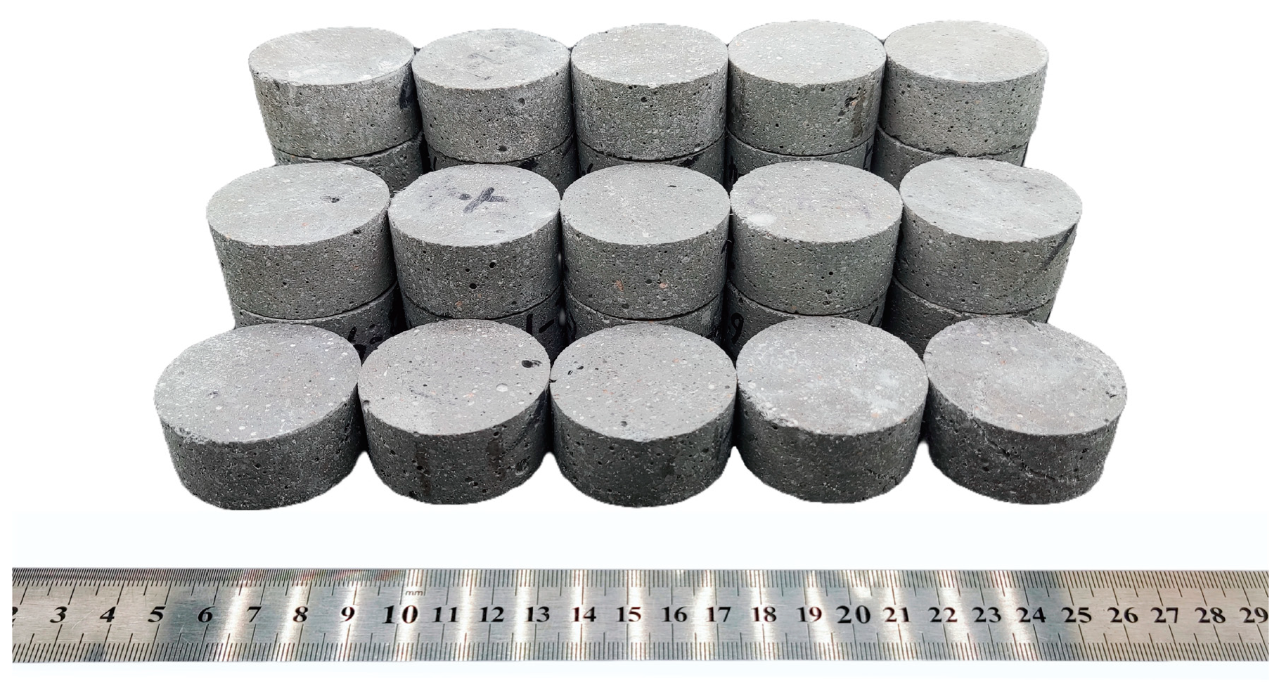
2.1. Material Mixing and Specimen Preparation
2.2. P-Wave Velocity Test
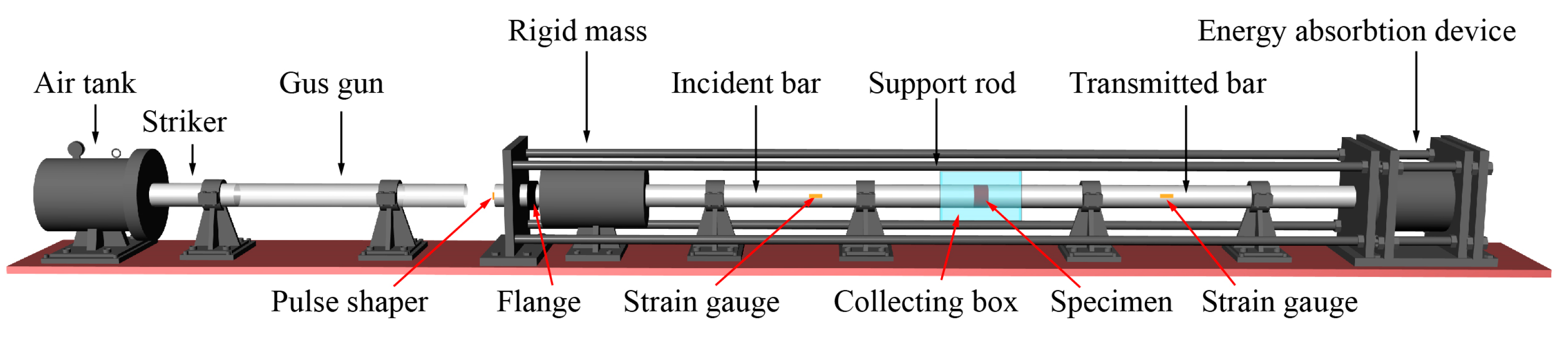
2.3. Split Hopkinson Pressure Bar (SHPB) System
2.4. Energy Dissipation Analysis
2.5. Sieve Analysis
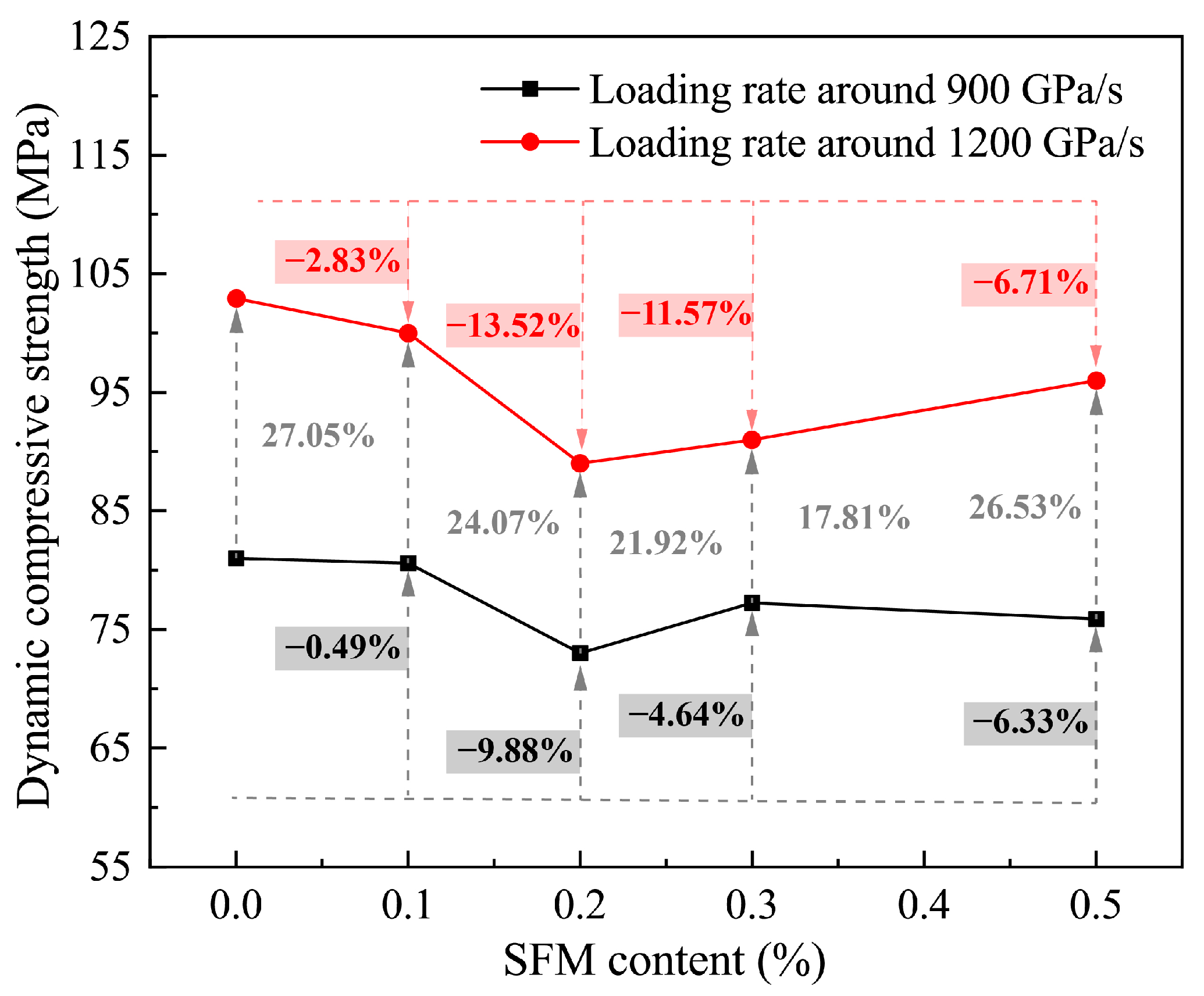
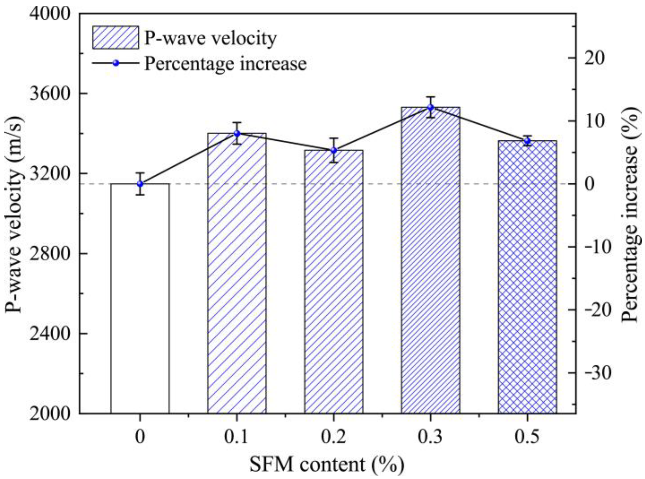
3. Results
3.1. P-Wave Velocity
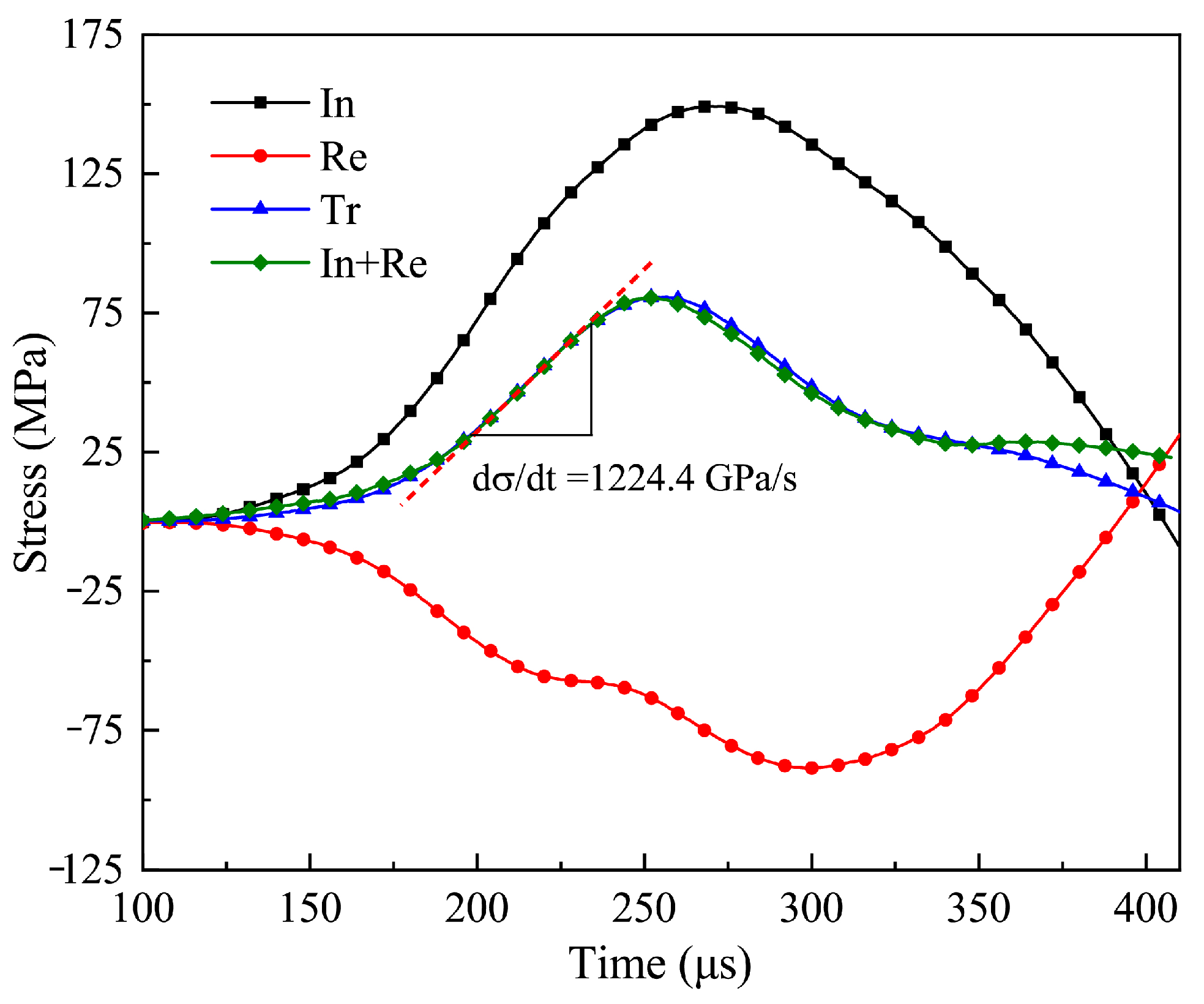
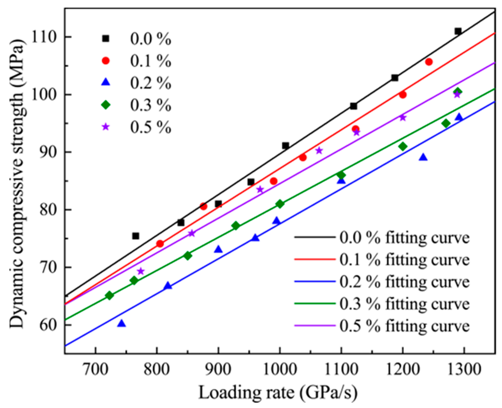
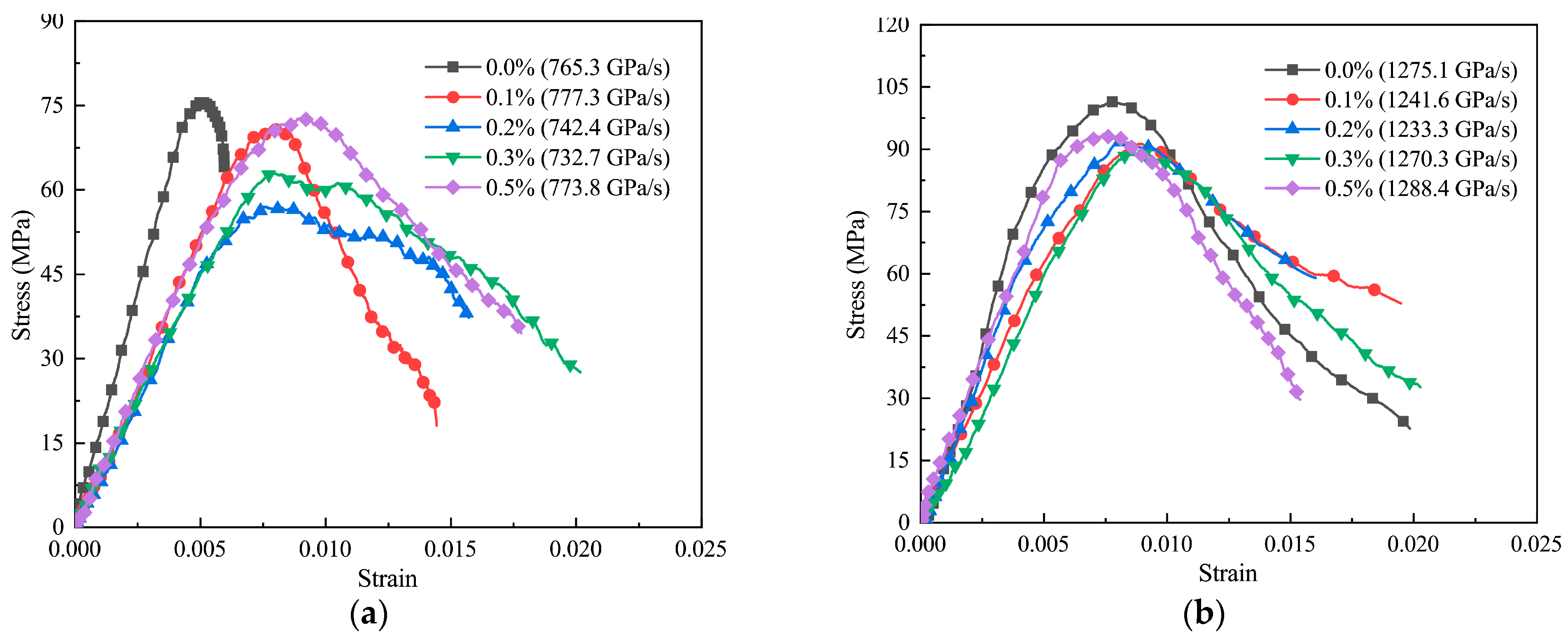
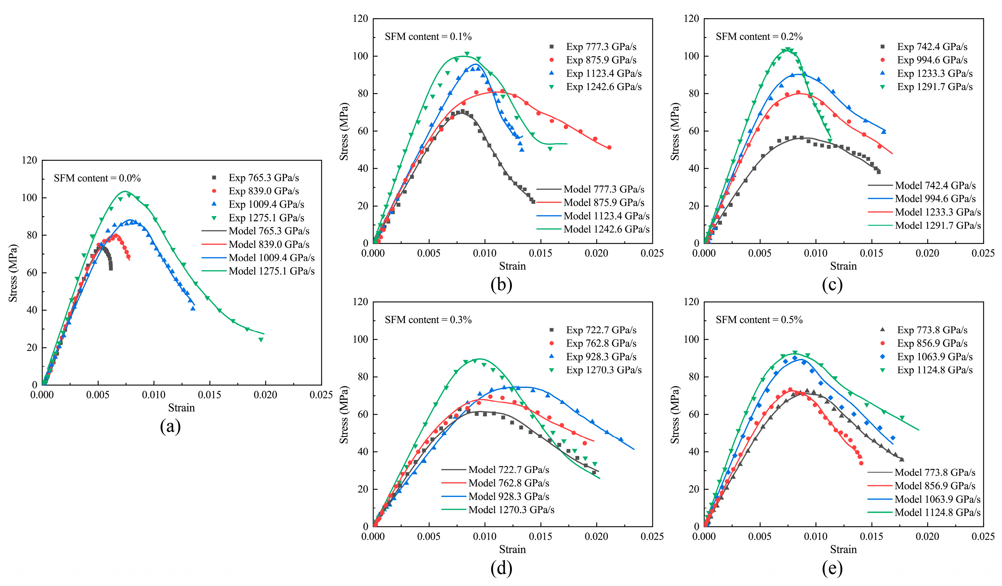
3.2. Dynamic Stress–Strain Curves and Strength Characteristics
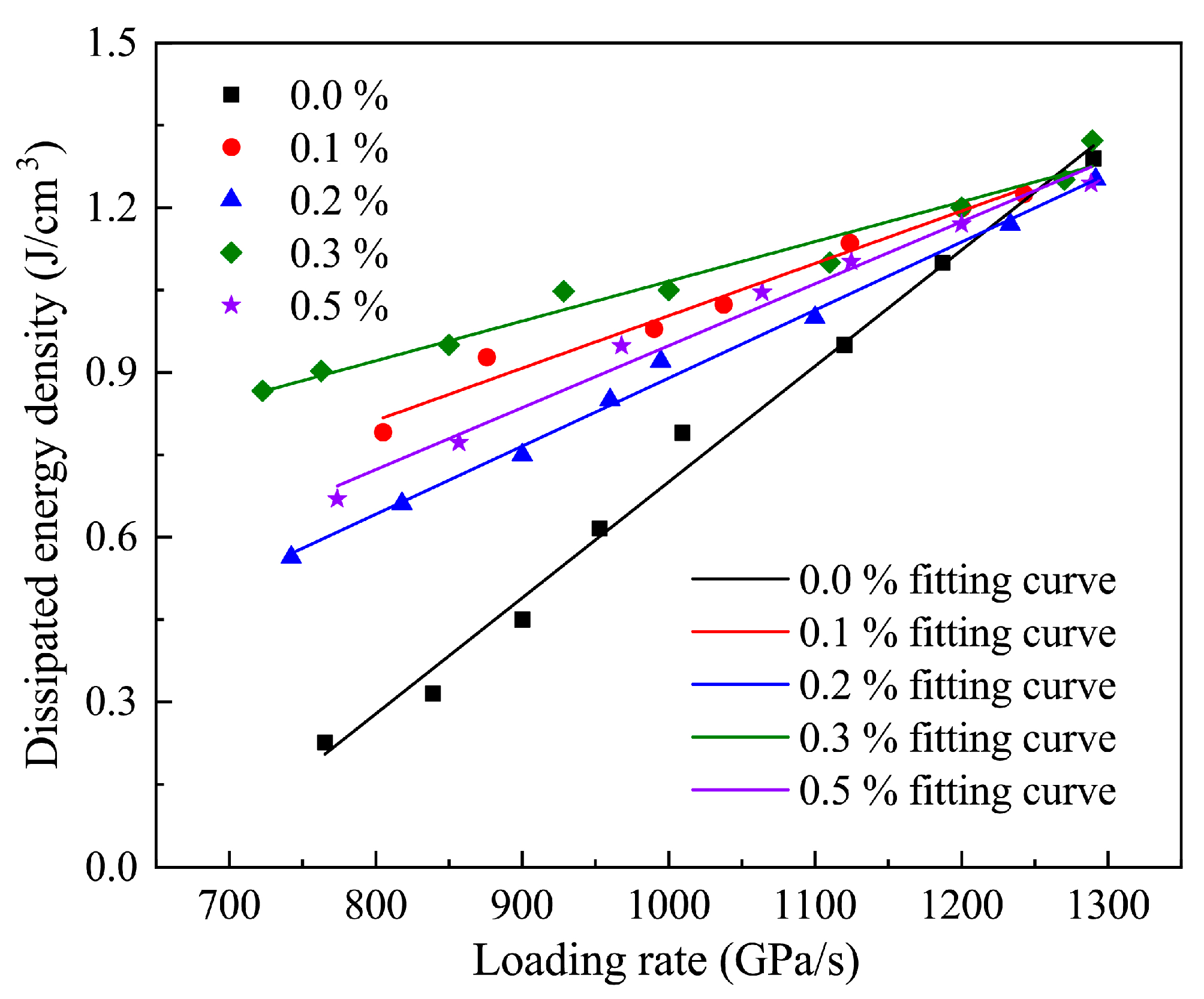
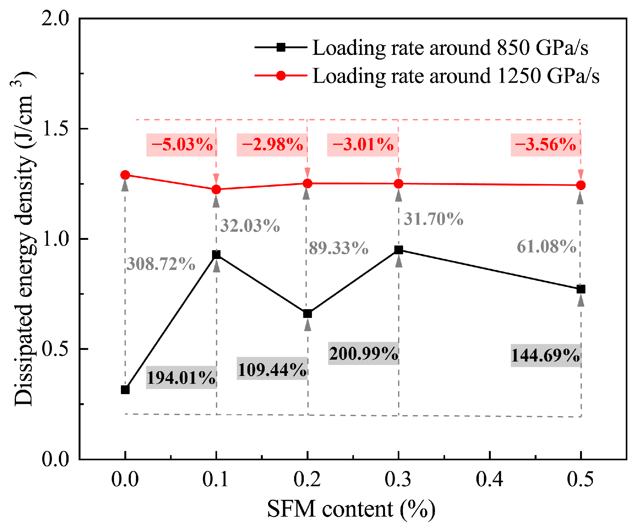
3.3. Dissipated Energy Density
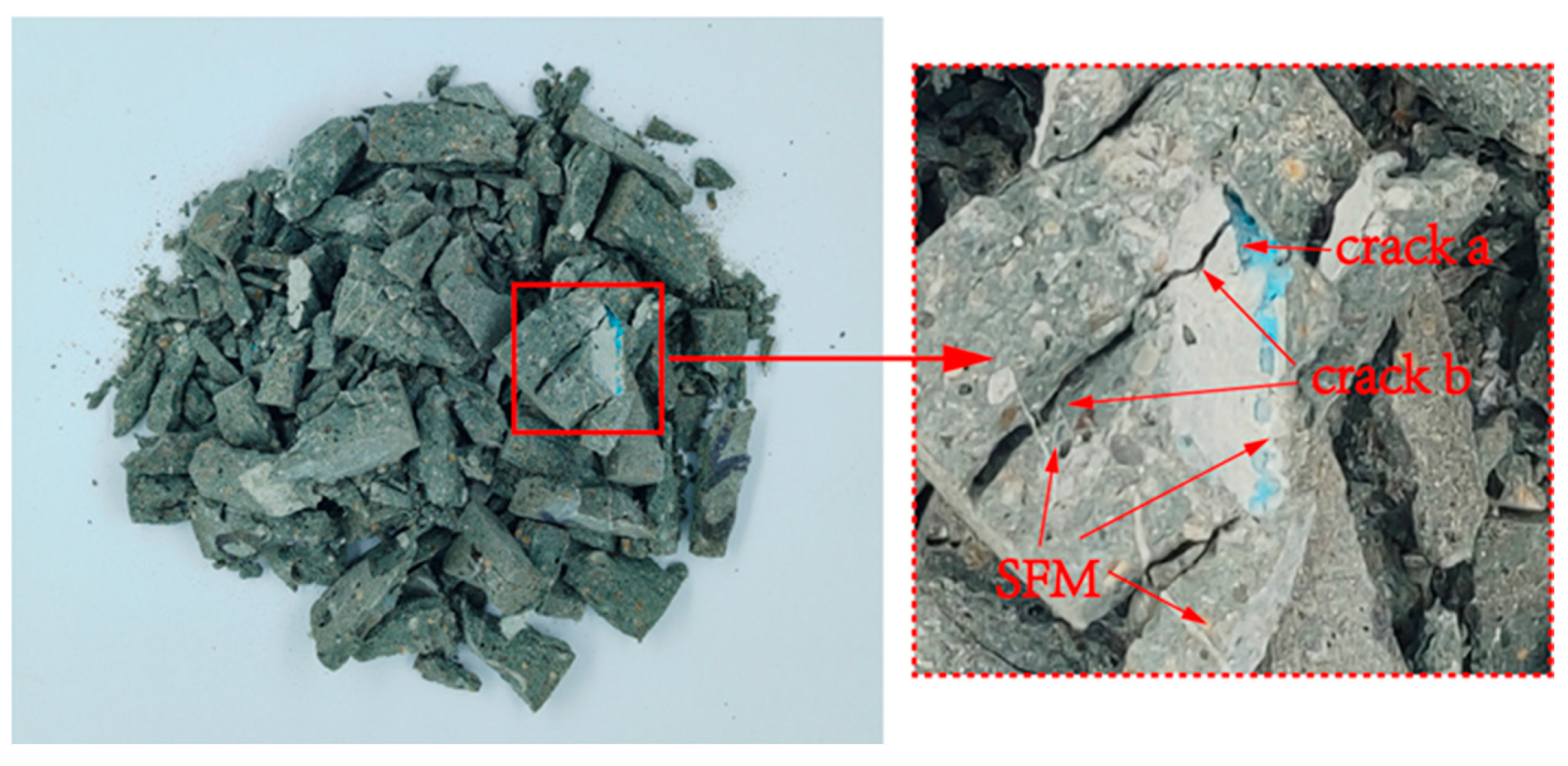
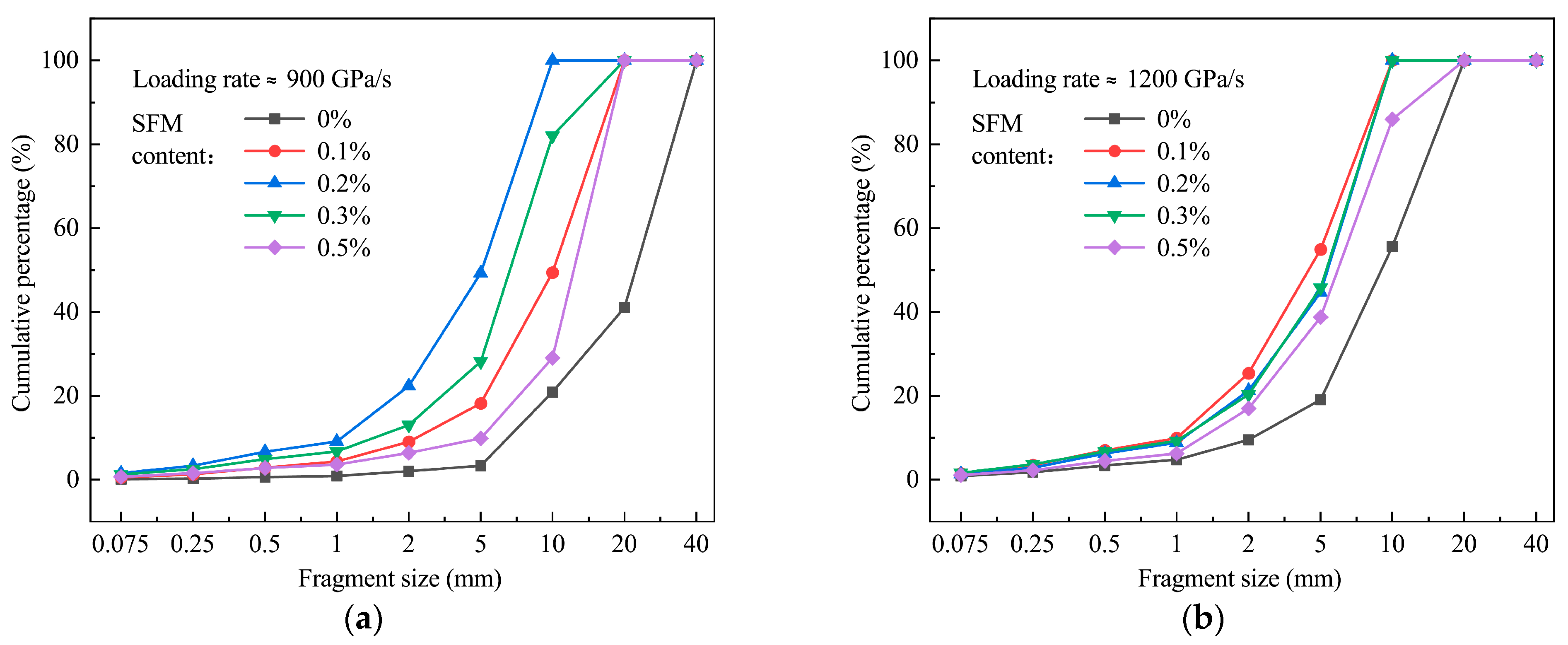
3.4. Specimen Fragmentation
3.5. Damage Constitutive Model Based on the Modified Weibull Distribution and Lemaitre Principle
4. Discussion
5. Conclusions
Author Contributions
Funding
Data Availability Statement
Conflicts of Interest
References
- Haji, J.Y.; Subramaniam, A.; Kumar, P.; Ramanathan, K.; Rajamani, A. State of personal protective equipment practice in indian intensive care units amidst COVID-19 pandemic: A nationwide survey. Indian J. Crit. Care Med. 2020, 24, 809–816. [Google Scholar] [CrossRef] [PubMed]
- Chua, M.H.; Cheng, W.R.; Goh, S.S.; Kong, J.H.; Li, B.; Lim, J.Y.C.; Mao, L.; Wang, S.X.; Xue, K.; Yang, L.; et al. Face masks in the new COVID-19 normal: Materials, testing, and perspectives. Research 2020, 2020, 7286735. [Google Scholar] [CrossRef] [PubMed]
- Prata, J.C.; Silva, A.L.P.; Walker, T.R.; Duarte, A.C.; Rocha-Santos, T. COVID-19 pandemic repercussions on the use and management of plastics. Environ. Sci. Technol. 2020, 54, 7760–7765. [Google Scholar] [CrossRef] [PubMed]
- Park, Y.; Bae, H.; Park, H.; Park, J.; Hong, J.; Kim, Y. The Unseen Threat: Microplastic Emissions from Face Masks and Limited Public Awareness. Korean J. Chem. Eng. 2024, 41, 237–247. [Google Scholar] [CrossRef]
- Aragaw, T.A. Surgical face masks as a potential source for microplastic pollution in the COVID-19 scenario. Mar. Pollut. Bull. 2020, 159, 111517. [Google Scholar] [CrossRef] [PubMed]
- Idrees, M.; Akbar, A.; Mohamed, A.M.; Fathi, D.; Saeed, F. Recycling of waste facial masks as a construction material, a step towards sustainability. Materials 2022, 15, 1810. [Google Scholar] [CrossRef] [PubMed]
- Kilmartin-Lynch, S.; Saberian, M.; Li, J.; Roychand, R.; Zhang, G.M. Preliminary evaluation of the feasibility of using polypropylene fibres from COVID-19 single-use face masks to improve the mechanical properties of concrete. J. Cleaner Prod. 2021, 296, 126460. [Google Scholar] [CrossRef] [PubMed]
- Chen, X.C.; Chen, X.F.; Liu, Q.; Zhao, Q.C.; Xiong, X.; Wu, C.X. Used disposable face masks are significant sources of microplastics to environment. Environ. Pollut. 2021, 285, 117485. [Google Scholar] [CrossRef] [PubMed]
- Fadare, O.O.; Okoffo, E.D. COVID-19 face masks: A potential source of microplastic fibers in the environment. Sci. Total Environ. 2020, 737, 140279. [Google Scholar] [CrossRef]
- Sullivan, G.L.; Delgado-Gallardo, J.; Watson, T.M.; Sarp, S. An investigation into the leaching of micro and nano particles and chemical pollutants from disposable face masks-linked to the COVID-19 pandemic. Water Res. 2021, 196, 117033. [Google Scholar] [CrossRef] [PubMed]
- Hu, X.; Lin, Z.D. Transforming waste polypropylene face masks into S-doped porous carbon as the cathode electrode for supercapacitors. Ionics 2021, 27, 2169–2179. [Google Scholar] [CrossRef] [PubMed]
- Fox, J.A.; Stacey, N.T. Process targeting: An energy based comparison of waste plastic processing technologies. Energy 2019, 170, 273–283. [Google Scholar] [CrossRef]
- Awoyera, P.O.; Effiong, J.U.; Olalusi, O.B.; Arunachalam, K.P.; de Azevedo, A.R.G.; Martinelli, F.R.B.; Monteiro, S.N. Experimental findings and validation on torsional behaviour of fibre-reinforced concrete beams: A review. Polymers 2022, 14, 1171. [Google Scholar] [CrossRef] [PubMed]
- Dey, D.; Srinivas, D.; Panda, B.; Suraneni, P.; Sitharam, T.G. Use of industrial waste materials for 3D printing of sustainable concrete: A review. J. Clean. Prod. 2022, 340, 130749. [Google Scholar] [CrossRef]
- Gong, J.H.; Ma, Y.W.; Fu, J.Y.; Hu, J.; Ouyang, X.W.; Zhang, Z.H.; Wang, H. Utilization of fibers in ultra-high performance concrete: A review. Compos. Part B-Eng. 2022, 241, 109995. [Google Scholar] [CrossRef]
- Wang, W.; Wei, W.Y.; Gao, S.; Chen, G.M.; Yuan, J.; Li, Y. Agricultural and aquaculture wastes as concrete components: A review. Front. Mater. 2021, 8, 762568. [Google Scholar] [CrossRef]
- Guo, H.; Tao, J.L.; Chen, Y.; Li, D.; Jia, B.; Zhai, Y. Effect of steel and polypropylene fibers on the quasi-static and dynamic splitting tensile properties of high-strength concrete. Constr. Build. Mater. 2019, 224, 504–514. [Google Scholar] [CrossRef]
- Li, F.R.; Chen, G.X.; Xu, G.Z.; Wu, Y.Y. An experimental study on the compressive dynamic performance of polypropylene fiber reinforced concrete for retaining structure under automobile collision magnitude. Adv. Civ. Eng. 2020, 2020, 8826006. [Google Scholar] [CrossRef]
- Liu, J.L.; Jia, Y.M.; Wang, J. Experimental study on mechanical and durability properties of glass and polypropylene fiber reinforced concrete. Fibers Polym. 2019, 20, 1900–1908. [Google Scholar] [CrossRef]
- Saberian, M.; Li, J.; Kilmartin-Lynch, S.; Boroujeni, M. Repurposing of COVID-19 single-use face masks for pavements base/subbase. Sci. Total Environ. 2021, 769, 145527. [Google Scholar] [CrossRef] [PubMed]
- Abd El Aal, A.; Abdullah, G.M.S.; Qadri, S.M.T.; Abotalib, A.Z.; Othman, A. Advances on concrete strength properties after adding polypropylene fibers from health personal protective equipment (PPE) of COVID-19: Implication on waste management and sustainable environment. Phys. Chem. Earth 2022, 128, 103260. [Google Scholar] [CrossRef] [PubMed]
- Paul, S.C.; Santo, M.A.H.; Nahid, S.A.; Majumder, A.R.; Al Mamun, M.F.; Basit, M.A.; Babafemi, A.J. Potential Use of COVID-19 Surgical Masks and Polyethylene Plastics in Developing Sustainable Concrete. J. Compos. Sci. 2023, 7, 402. [Google Scholar] [CrossRef]
- Maloba, J.W.; Kiambigi, J.M.; Kabubo, C.K. Reutilizing Single-Use Surgical Face Masks to Improve the Mechanical Properties of Concrete: A Feasibility Study. Eng. Technol. Appl. Sci. Res. 2023, 13, 10511–10516. [Google Scholar] [CrossRef]
- Ajam, L.; Trabelsi, A.; Kammoun, Z. Valorisation of face mask waste in mortar. Innov. Infrastruct. Solut. 2022, 7, 130. [Google Scholar] [CrossRef]
- Avudaiappan, S.; Cendoya, P.; Arunachalam, K.P.; Maureira-Carsalade, N.; Canales, C.; Amran, M.; Parra, P.F. Innovative Use of Single-Use Face Mask Fibers for the Production of a Sustainable Cement Mortar. J. Compos. Sci. 2023, 7, 214. [Google Scholar] [CrossRef]
- Li, X.; Xia, K.W.; Yao, W.; Xu, Y. Investigation on the dynamic tensile behaviour of rubberized mortar using the Brazilian disc method. Theor. Appl. Fract. Mech. 2022, 119, 103339. [Google Scholar] [CrossRef]
- Abna, A.; Mazloom, M. Flexural properties of fiber reinforced concrete containing silica fume and nano-silica. Mater. Lett. 2022, 316, 132003. [Google Scholar] [CrossRef]
- Garg, R.; Garg, R. Performance evaluation of polypropylene fiber waste reinforced concrete in presence of silica fume. In Proceedings of the International Conference on Advanced Materials Behavior and Characterization (ICAMBC), Chennai, India, 24–26 April 2021; pp. 809–816. [Google Scholar]
- Xiang, Y.; Song, Q.F.; Gu, W.Z. Decontamination of surgical face masks and N95 respirators by dry heat pasteurization for one hour at 70 degrees C. Am. J. Infect. Control 2020, 48, 880–882. [Google Scholar] [CrossRef] [PubMed]
- CECS 13; Standard Test Methods for Fiber Reinforced Concrete. China Construction Engineering Association: Beijing, China, 2009.
- Xu, H.Y.; Shao, Z.M.; Wang, Z.J.; Cai, L.B.; Li, Z.; Jin, H.S.; Chen, T.W. Experimental study on mechanical properties of fiber reinforced concrete: Effect of cellulose fiber, polyvinyl alcohol fiber and polyolefin fiber. Constr. Build. Mater. 2020, 261, 120610. [Google Scholar] [CrossRef]
- Xia, K.; Yao, W. Dynamic rock tests using split Hopkinson (Kolsky)bar system—A review. J. Rock Mech. Geotech. Eng. 2015, 7, 27–59. [Google Scholar] [CrossRef]
- Zhou, Y.X.; Xia, K.; Li, X.B.; Li, H.B.; Ma, G.W.; Zhao, J.; Zhou, Z.L.; Dai, F. Suggested methods for determining the dynamic strength parameters and mode-I fracture toughness of rock materials. Int. J. Rock Mech. Min. Sci. 2012, 49, 105–112. [Google Scholar] [CrossRef]
- Demirboga, R.; Turkmen, I.; Karakoc, M.B. Relationship between ultrasonic velocity and compressive strength for high-volume mineral-admixtured concrete. Cem. Concr. Res. 2004, 34, 2329–2336. [Google Scholar] [CrossRef]
- Yao, W.; Xu, Y.; Wang, W.; Kanopolous, P. Dependence of dynamic tensile strength of Longyou sandstone on heat-treatment temperature and loading rate. Rock Mech. Rock Eng. 2015, 49, 3899–3915. [Google Scholar] [CrossRef]
- Wang, S.; Xu, Y.; Xia, K.W.; Tong, T.Y. Dynamic fragmentation of microwave irradiated rock. J. Rock Mech. Geotech. Eng. 2021, 13, 300–310. [Google Scholar] [CrossRef]
- Xia, K.; Nasseri, M.H.B.; Mohanty, B.; Lu, F.; Chen, R.; Luo, S.N. Effects of microstructures on dynamic compression of Barre granite. Int. J. Rock Mech. Min. Sci. 2008, 45, 879–887. [Google Scholar] [CrossRef]
- Xu, Y.; Yao, W.; Wang, S.; Xia, K.W. Investigation of the heat-treatment effect on rock fragmentation characteristics using the dynamic ball compression test. Rock Mech. Rock Eng. 2020, 53, 2095–2108. [Google Scholar] [CrossRef]
- Wu, B.B.; Yang, L.; Mei, Y.; Sun, Y.H.; Liu, J.M.; Shen, J. Effects of Freeze-Thaw Cycling on Dynamic Compressive Strength and Energy Dissipation of Sandstone. Minerals 2022, 12, 1331. [Google Scholar] [CrossRef]
- Ren, W.B.; Xu, J.Y. Fractal Characteristics of Concrete Fragmentation under Impact Loading. J. Mater. Civ. Eng. 2017, 29, 04016244. [Google Scholar] [CrossRef]
- ASTM C136-06; Standard Test Method for Sieve Analysis of Fine and Coarse Aggregates. ASTM: West Conshohocken, PA, USA, 2006.
- Yap, S.P.; Alengaram, U.J.; Jumaat, M.Z. Enhancement of mechanical properties in polypropylene- and nylon-fibre reinforced oil palm shell concrete. Mater. Des. 2013, 49, 1034–1041. [Google Scholar] [CrossRef]
- Shen, D.J.; Liu, X.Z.; Zeng, X.; Zhao, X.G.; Jiang, G.Q. Effect of polypropylene plastic fibers length on cracking resistance of high performance concrete at early age. Constr. Build. Mater. 2020, 244, 117874. [Google Scholar] [CrossRef]
- Peng, R.D.; Ju, Y.; Wang, J.G.; Xie, H.P.; Gao, F.; Mao, L.T. Energy Dissipation and Release During Coal Failure Under Conventional Triaxial Compression. Rock Mech. Rock Eng. 2015, 48, 509–526. [Google Scholar] [CrossRef]
- Lemaitre, J. How to use damage mechanics. Nucl. Eng. Des. 1984, 80, 233–245. [Google Scholar] [CrossRef]
- Ji, Y.C.; Wang, D.Y. Constitutive model of waste brick concrete based on Weibull strength theory. Case Stud. Constr. Mater. 2023, 18, e01738. [Google Scholar] [CrossRef]
- Chen, X.D.; Wu, S.X.; Zhou, J.K. Compressive Strength of Concrete Cores with Different Lengths. J. Mater. Civ. Eng. 2014, 26, 04014027. [Google Scholar] [CrossRef]
- Khazaei, C.; Hazzard, J.; Chalaturnyk, R. Damage quantification of intact rocks using acoustic emission energies recorded during uniaxial compression test and discrete element modeling. Comput. Geotech. 2015, 67, 94–102. [Google Scholar] [CrossRef]
- Wang, F.; Wang, H.B.; Xu, Y.; Cheng, B.; Wang, Q.Q. Analysis of energy dissipation characteristics of damaged sandstone under impact load. Shock Vib. 2021, 2021, 4200452. [Google Scholar] [CrossRef]
- Gul, R.; Demirboga, R.; Guvercin, T. Compressive strength and ultrasound pulse velocity of mineral admixtured mortars. Indian J. Eng. Mat. Sci. 2006, 13, 18–24. [Google Scholar]
- Li, X.; Wang, S.; Xu, Y.; Yao, W.; Xia, K.W.; Lu, G.M. Effect of microwave irradiation on dynamic mode-I fracture parameters of Barre granite. Eng. Fract. Mech. 2020, 224, 106748. [Google Scholar] [CrossRef]
- Kilmartin-Lynch, S.; Roychand, R.; Saberian, M.; Li, J.; Zhang, G. Application of COVID-19 single-use shredded nitrile gloves in structural concrete: Case study from Australia. Sci. Total Environ. 2022, 812, 151423. [Google Scholar] [CrossRef]
- Xu, Y.; Cui, T.; Wu, B.; Wang, Z.; Song, Y. Dynamic mode I fracture characteristics of jute fiber-reinforced rubber mortar. Eng. Fract. Mech. 2023, 292, 109649. [Google Scholar] [CrossRef]
- Mohammadhosseini, H.; Yatim, J.M. Evaluation of the effective mechanical properties of concrete composites using industrial waste carpet fiber. INAE Lett. 2017, 2, 1–12. [Google Scholar] [CrossRef]
- Jamshidi, M.; Karimi, M. Characterization of polymeric fibers as reinforcements of cement-based composites. J. Appl. Polym. Sci. 2010, 115, 2779–2785. [Google Scholar] [CrossRef]
- Angelin, A.F.; Miranda, E.J.P.; Dos Santos, J.M.C.; Lintz, R.C.C.; Gachet-Barbosa, L.A. Rubberized mortar: The influence of aggregate granulometry in mechanical resistances and acoustic behavior. Constr. Build. Mater. 2019, 200, 248–254. [Google Scholar] [CrossRef]
- Chen, L.J.; Zhang, X.X.; Liu, G.M. Analysis of dynamic mechanical properties of sprayed fiber-reinforced concrete based on the energy conversion principle. Constr. Build. Mater. 2020, 254, 119167. [Google Scholar] [CrossRef]
- Du, B.; Ma, H.W.; Lin, L. Dynamic split tension and energy dissipation of fiber concrete under impact loading effect. In Proceedings of the International Conference on Electromechanical Control Technology and Transportation (ICECTT), Zhuhai, China, 31 October–1 November 2015; pp. 91–100. [Google Scholar]


| Material | P.O 42.5 Cement | Standard Sand (ISO-6790) | Fly Ash | Silica Fume | Mineral Powder | Water | Water Reducing Agent | Defoamer | SFM |
|---|---|---|---|---|---|---|---|---|---|
| FM0 | 900 | 729 | 90 | 180 | 135 | 234.9 | 26.1 | 2.61 | 0 |
| FM1 | 0.91 | ||||||||
| FM2 | 1.82 | ||||||||
| FM3 | 2.73 | ||||||||
| FM5 | 4.55 |
Disclaimer/Publisher’s Note: The statements, opinions and data contained in all publications are solely those of the individual author(s) and contributor(s) and not of MDPI and/or the editor(s). MDPI and/or the editor(s) disclaim responsibility for any injury to people or property resulting from any ideas, methods, instructions or products referred to in the content. |
© 2024 by the authors. Licensee MDPI, Basel, Switzerland. This article is an open access article distributed under the terms and conditions of the Creative Commons Attribution (CC BY) license (https://creativecommons.org/licenses/by/4.0/).
Share and Cite
Nie, Q.; Wu, B.; Wang, Z.; Dai, X.; Chen, L. Incorporation of Disposed Face Mask to Cement Mortar Material: An Insight into the Dynamic Mechanical Properties. Buildings 2024, 14, 1063. https://doi.org/10.3390/buildings14041063
Nie Q, Wu B, Wang Z, Dai X, Chen L. Incorporation of Disposed Face Mask to Cement Mortar Material: An Insight into the Dynamic Mechanical Properties. Buildings. 2024; 14(4):1063. https://doi.org/10.3390/buildings14041063
Chicago/Turabian StyleNie, Qiong, Bangbiao Wu, Zheng Wang, Xiaoyan Dai, and Lingyun Chen. 2024. "Incorporation of Disposed Face Mask to Cement Mortar Material: An Insight into the Dynamic Mechanical Properties" Buildings 14, no. 4: 1063. https://doi.org/10.3390/buildings14041063
APA StyleNie, Q., Wu, B., Wang, Z., Dai, X., & Chen, L. (2024). Incorporation of Disposed Face Mask to Cement Mortar Material: An Insight into the Dynamic Mechanical Properties. Buildings, 14(4), 1063. https://doi.org/10.3390/buildings14041063