Article

Research on the System Design and Target Recognition Method of the Rebar-Tying Robot

1
China Railway NO. 9 Engineering Group Co., Ltd., Shenyang 110005, China
2
Liaoning Provincial Intelligent Construction Technology Innovation Center for Rail Transit Engineering, Shenyang 110100, China
3
Institutes for Robotics and Intelligent Manufacturing, Chinese Academy of Sciences, Shenyang 110169, China
*
Authors to whom correspondence should be addressed.
Buildings 2024, 14(3), 838; https://doi.org/10.3390/buildings14030838
Submission received: 1 February 2024 / Revised: 14 March 2024 / Accepted: 19 March 2024 / Published: 20 March 2024
(This article belongs to the Special Issue Robotics, Automation and Digitization in Construction)

Abstract

:
In the construction industry, the construction process of rebar tying is highly dependent on manual operation, which leads to a wide range of work areas, high labor intensity, and limited efficiency. Therefore, robot technology for automatic rebar tying has become an inevitable trend in on-site construction. This study aims to develop a planar rebar-tying robot that can achieve autonomous navigation, precise positioning, and efficient tying on a plane rebar mesh without boundaries. Our research covers the overall design of the robot control systems, the selection of key hardware, the development of software platforms, and the optimization of core algorithms. Specifically, to address the technical challenges of accurately recognizing the tying position and status, we propose an innovative two-stage identification method that combines a depth camera and an industrial camera to obtain image information about the area to be tied. The effectiveness of the planar rebar-tying robot system, including the recognition method proposed in this study, was verified by experiments on a rebar mesh demonstration platform. The following application of our robot system in the field of the Shenyang Hunnan Science and Technology City Phase IV project achieved satisfactory performance. It is shown that this research has made a unique and significant innovation in the field of automatic rebar tying.

1. Introduction

In the construction industry, the rebar tying process has traditionally been regarded as a heavy and labor-intensive task [1,2]. This is even more so when dealing with large-scale bearing platforms and bridge deck slabs. As shown in Figure 1, the vast working area and high-intensity labor requirements make the operating environment extremely harsh. This manual-dependent operation imposes a heavy burden on the workers carrying out the tasks and poses two serious challenges to projects: (1) the high-intensity and time-consuming tying process poses a considerable threat to the health of the workers; (2) this inefficient way of working also slows down the overall progress of the project [3,4]. More critically, as a key step in almost all large-scale civil construction projects, the progress of rebar tying is directly related to the completion time of the entire project [5]. The intelligent upgrading of the construction industry is crucial for future development [6,7,8], and the implementation of automated rebar tying is an indispensable and important part of this process [9,10].
In recent years, significant progress has been made in the field of construction robotics [11,12,13]. Currently, there is little research on automatic rebar-tying robots. These studies are mainly oriented to two core problems: (1) Traditional robots cannot walk on the surface of complex planes of steel mesh. (2) They have difficulty identifying rebar intersections in complex environments. Momeni et al. [14] simulated the automated manufacturing process of rebar cages based on a 3D-BIM model and proposed a path-planning algorithm for rebar tying. However, this research was conducted in a laboratory using a stationary robotic arm to place rebar, no research was conducted on rebar tying. In addition, it was not a mobile robot, which did not address the problem of practical application on the construction site. Jin et al. [15] designed a crawler-type rebar-tying robot, but the experiments showed that the robot was prone to displace untied rebar when traveling and steering in practical tests and, thus, fails to be widely applied. Moreover, there are two rebar-tying robots available on the market, TyBot and Ironbot, but both need to be used with gantries [16]. These gantry robots are not only costly and time-consuming to install, but also complex to operate and require specialized technicians to operate and maintain them. In addition, these robots can only be used for linear construction projects such as bridge decks and highways, but not for projects such as a building construction, which lacks flexibility. In summary, there is a lack of small mobile rebar-tying robots that can be flexibly applied to a variety of construction projects with a simple operation and low cost.
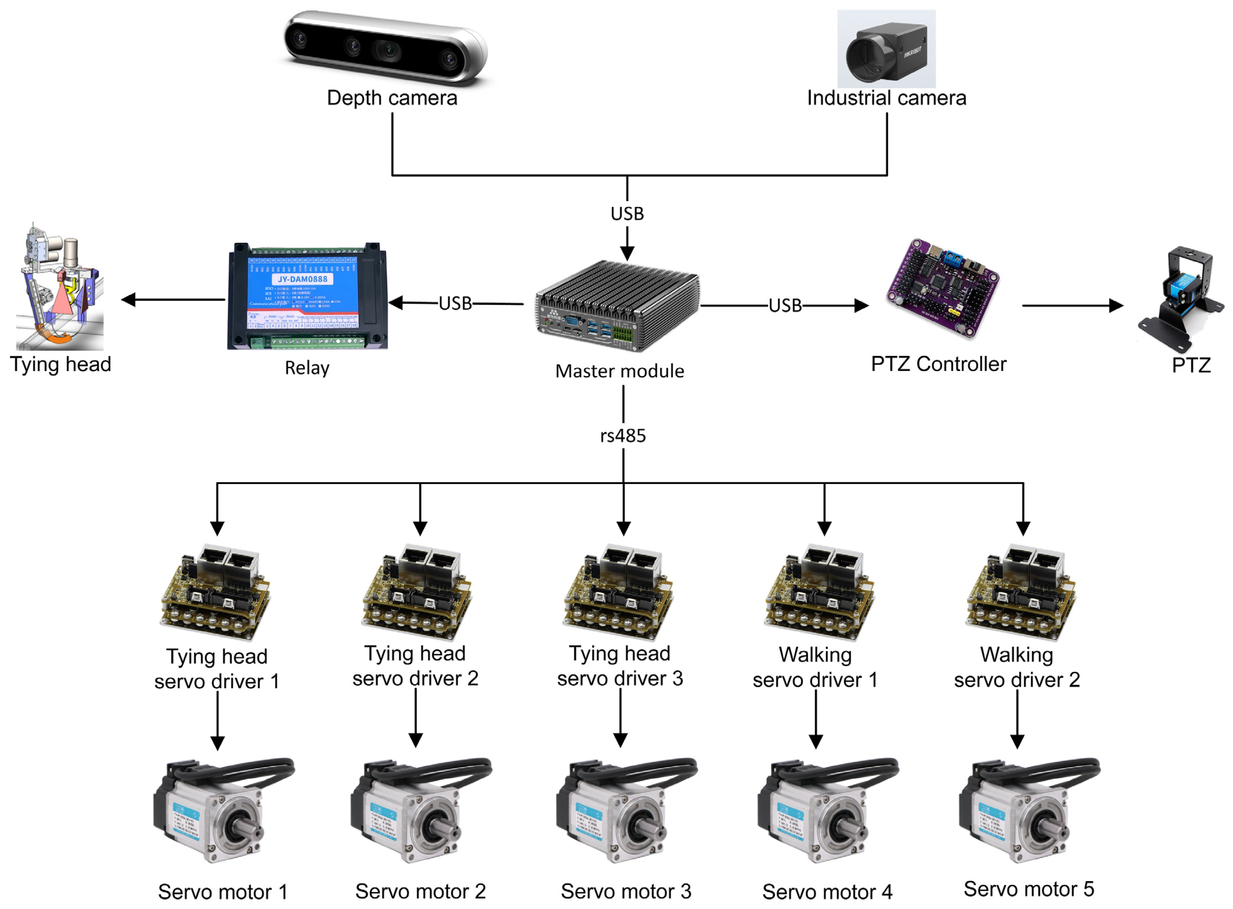
To address the actual demand for planar rebar tying, we independently developed a walking robot that can walk on the surface of rebar and designed a new control system for this type of robot based on the robot operating system (ROS) [17,18,19] combined with visual recognition technology. The self-developed rebar-tying robot can realize autonomous navigation on large-scale bearing platforms and bridge deck slabs without boundary conditions, the autonomous positioning of the tying of rebar intersection locations, and the intelligent planning of tying paths. First, based on the ROS system, we designed and researched the hardware and software of the robot control system. The final program employed multiple sensors, edge computing devices, and an ROS system to connect the communications of each node. The central control system and the servo motor used the Modbus communication protocol and a bus transmission form for communication. This approach breaks through the traditional use of PLCs or microcontrollers for servo control and realizes the integrated solution of a sensor-central control system-servo control. The automatic rebar-tying robot system recognizes the spatial position of the rebar intersection point through machine vision, and the tying module completes the tying, moves to the next rebar intersection point according to the set path, and continues the tying operation.
The accurate visual recognition of rebar intersections is one of the key technologies for rebar tying. Wang et al. [20] proposed a rebar intersection point detection algorithm based on Mask R-CNN. Moreover, it also combines with the BIM software (Revit and Lumion 11) and introduces a dataset enhancement method, which significantly reduces the difficulty of deep neural network training and effectively improves the accuracy of recognition. Dong et al. [21] proposed a YOLOv4-based identification and localization method for rebar tying, which achieves the effective identification of the location of tying points, but this method does not further judge the tying status of the rebar. It is worth noting that these methods are mainly validated on a demonstration platform under laboratory conditions; they do not use construction site rebar pictures for model training or validation and, thus, have not yet fully taken into account the complex environment and variable factors of the actual construction site; therefore, the proposed model may be overfitted and difficult to apply in practice.
To reduce the difficulty of identifying rebar intersections, reduce the damage of the tying head due to inaccurate identification, and achieve the long-term stable operation of the robot in the field, we propose a two-stage identification method that can be applied to the rebar-tying robot for the fast and accurate identification of the tying position and state. The pictures of the area to be tied are obtained by the fusion operation of a depth camera and a high-precision industrial camera, and the tying efficiency and accuracy are optimized through the coordination of the two cameras. In the master module, a target detection module based on deep learning and an outlier judgment module based on a clustering algorithm is designed. The convolutional neural network model YOLOv5 [22], which has been widely used in the task of target detection, is chosen for the target detection module. YOLOv5 can directly determine the location of the rebar intersection position and determine the tying status of the rebar-tying robot. The overall system architecture diagram for this paper is shown in Figure 2.
The principal contributions of this paper are summarized as follows. First, this paper details the design and implementation of a planar rebar-tying robot that can walk on the surface of rebar, and introduces a new control system for this robot. It addresses the gap of small mobile rebar-tying robots that can be flexibly applied to a variety of construction projects with a simple operation. Second, this paper introduces an innovative two-stage identification method that combines a depth camera and an industrial camera to accurately recognize the tying position and status. This method overcomes a key technical bottleneck in the automation of the rebar-tying process. Third, the effectiveness of the planar rebar-tying robot system and its recognition method has been fully verified on a rebar mesh demonstration platform and has been practically applied in a real-world construction project. Therefore, this research has made a unique and significant innovation in the field of automatic rebar tying. The outline of this paper is as follows: Section 2 presents an overview of the robot control system scheme design. In Section 3, the robot target recognition algorithm for navigation and tying is described and the results are validated experimentally on the demonstration platform site in Section 4. In Section 5, we discuss the idea in more depth. Finally, Section 6 summarizes the paper and presents and discusses further future research directions.

2. Robot Control System Scheme Design

The developed planar rebar-tying robot is shown in Figure 3. The robot is oriented toward planar rebar tying in the outdoor environment, and the robot can recognize the location of the rebar intersection and the state of rebar tying independently, complete automatic tying according to the recognized information, and move to the next area for tying after the tying is completed with an autonomous planning path. The robot control system needs to consider both accuracy and speed; that is, it needs to be based on the machine’s vision to realize the accurate recognition of the state and position of the rebar tying intersection, as well as the fast response and accurate execution of the tying and walking mechanism.

2.1. Hardware Design

The hardware composition of the control system includes the sensing module, master module, power supply module, and drive module. The sensing module consists of a depth camera and an industrial camera and is responsible for transmitting the collected scene information to the master module. The depth camera can increase the distance information compared to the traditional camera. It is installed at the highest point of the whole robot and is equipped with a two-axis pan tilt zoom (PTZ), which is responsible for robot navigation and tying path planning; the industrial camera features high precision and is installed in the vicinity of the tying head, which can improve the recognition accuracy. Our rebar-tying robot system requires the utilization of both of the cameras. The master module adopts a high-computing power edge computing device, which makes decisions on path planning, autonomous positioning, and autonomous tying according to the type of task and then sends commands to different motor drives. The tying drive employs a 24 V 100 W servo motor, with a rated torque of 0.32 Nm, equipped with 1:7 planetary gearboxes, with a control torque of 2.24 Nm. The walking drive employs a 48 V 400 W servo motor, with a rated torque of 1.27 Nm, equipped with 1:50 planetary gearboxes, with a control torque of 63.5 Nm. The power module employs a lithium battery with a high energy density and a voltage of 48 V. The specific parameters are shown in Table 1.
The drive module consists of a servo motor and servo drive, in which the servo drive adopts the CANopen and Modbus absolute servo drive, adopts the communication control mode, and is controlled by the master module through the DB9 interface with the RS485 protocol for bus communication. The master module sends and receives the serial port signals via a Python series and sends hexadecimal commands to the servo drive according to its Modbus dictionary, which directly controls the servo motor. The communication between the various modules of this robot system is shown in Figure 4. The servo motor uses RS485 bus communication, and the rest of the sensors use USB and Ethernet communication.

2.2. Software Design

The software control module of the robot system in this paper is developed with a Linux system based on Python. The main role of the software control module is to realize mutual communication among system modules, display key information, and analyze the data under the robot operating system (ROS). As the most widely used open-source robot software platform, the ROS integrates a large number of tools, libraries, and protocols to simplify the control of the robot and greatly improve the efficiency of robot development. The main tasks of the planar rebar-tying robot include the following three steps: (1) the robot can autonomously recognize the rebar intersection point and the rebar tying state; (2) the robot can complete the automatic tying according to the recognized intersection point information; and (3) the robot can autonomously navigate and plan the tying path. The control system software design is divided into the following three layers: the perception layer, the decision layer, and the execution layer. The whole system software design architecture is shown in Figure 5.
The control logic of walking and tying tasks is the core of the robot’s control. Figure 6 shows the flow chart of the robot detection, walking, and tying control logic designed in this work, and Algorithm 1 shows the corresponding pseudocode. Large-scale bearing platforms and bridge deck slabs are characterized by a large area, and it is impossible to perceive the boundary state; therefore, in the execution of the walking task, the perception layer adjusts the field of view of the depth camera through the PTZ, and the depth camera obtains information about the number of rebar intersections in the field of view and sends the results to the decision layer. The decision layer is responsible for the planning and coordination of the walking behavior of the robot and uses the ‘master and navigation program’ to process the received information and control the execution layer. The execution layer includes the control of the PZT and the walking mechanism, which are controlled by the ‘PZT control program’ and the ‘walking motor control program’, respectively.
Algorithm 1 Control Algorithms for the Robot’s Detection, Walking, and Tying Tasks
Robot Initialization:
Number of steps to the right direction: M = 0
PTZ forward/backward directional pointer: A = 1 (forward)
PTZ left/right directional pointer: B = 1 (right)
Threshold for intersections in the field of view (FOV): thresh = 10
Robot execution signal: Active = True
Robot execution:
while (Active=True) do
    Detecting the number of intersections in FOV of A-direction: N1
    if N1 > thresh do
      Walking one step along A-direction
      Completing tying task within FOV via dual-cam visual inspection (VIS)
    else do
      Detecting the number of intersections in FOV of B-direction: N2
      if N2 > thresh do
        Walking one step along B-direction
        PTZ forward/backward directional pointer: A = −A
        Completing tying task within FOV via dual-cam visual inspection (VIS)
        if B = 1 do
          Number of steps to the right direction: M = M + 1
        end if
      else do
        if B = 1 do
          PTZ left/right directional pointer: B = −B
          Walking M steps along the B-direction
          PTZ forward/backward directional pointer: A = −A
        else do
          Robot execution signal: Active = False
        end if
      end if
    end if
end

3. Robot Target Recognition Algorithm

Since each rebar intersection is less than 32 × 32 pixels in the image, this type of intersection is a type of small target detection problem with a low resolution and limited pixels. This paper proposes a two-stage recognition method that can be applied to rebar-tying robots for the fast and accurate determination of the tying position and state. A picture of the area to be tied is acquired by the fusion operation of a depth camera and a high-precision industrial camera. In addition, the method integrates deep neural networks and clustering algorithms to further improve the recognition accuracy of rebar tying intersections.

3.1. Two-Stage Identification Method

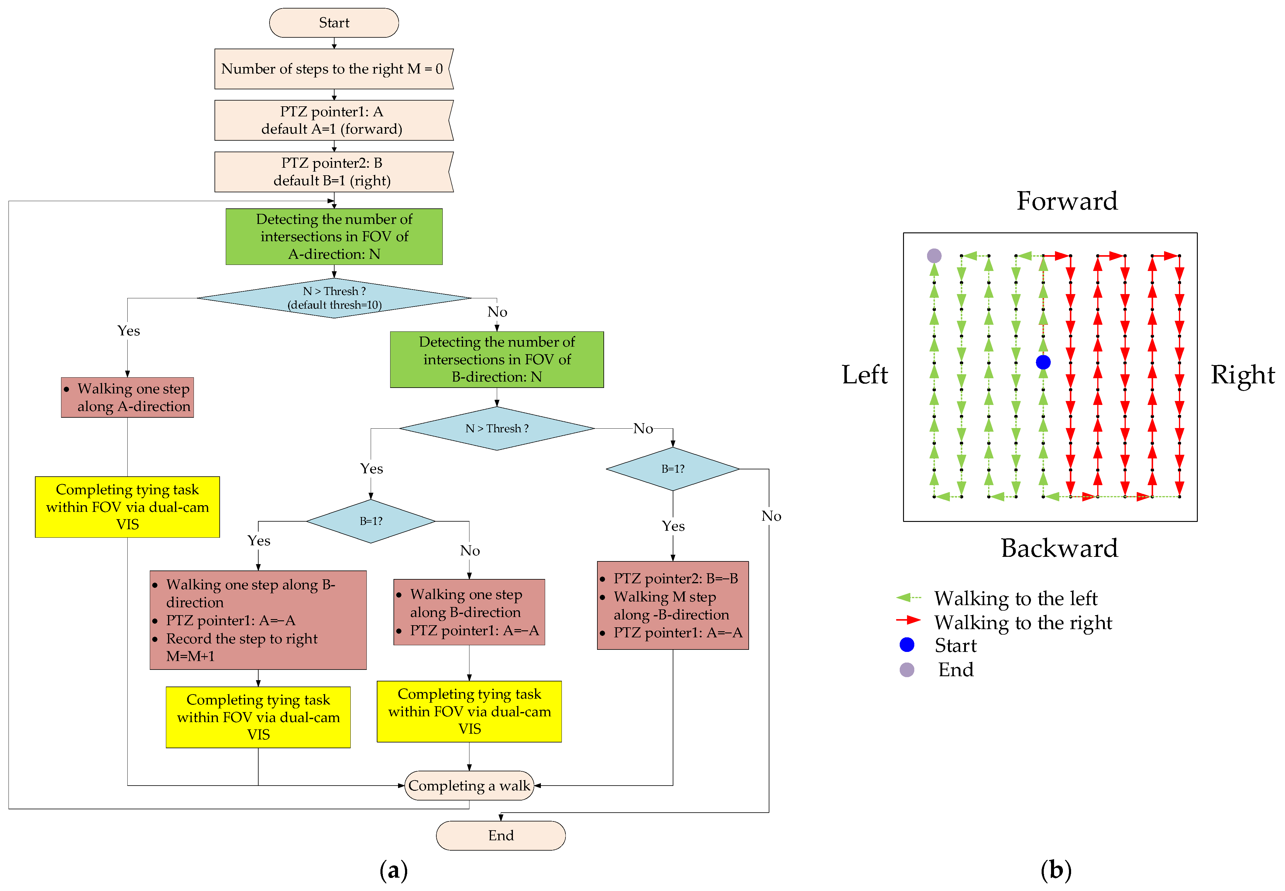
The tying control flowchart based on the dual-camera visual detection is shown in 
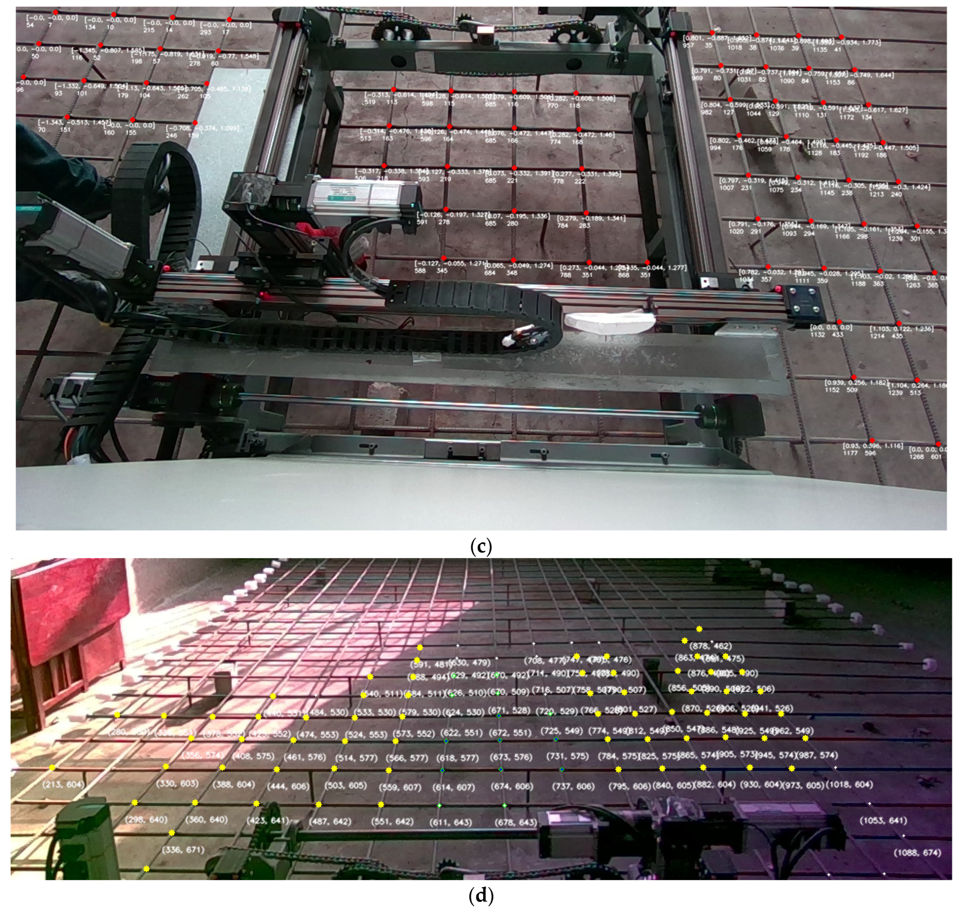
Figure 7. When performing the tying task, the perception layer obtains the location and state information of the rebar intersection in the area to be tied through the ‘dual-camera visual detection program’ and sends the results to the decision layer; the decision layer is responsible for planning and coordinating the tying behavior of the robot. It uses the information obtained by the ‘master and navigation program’ to process the information and then combines the ‘data buffer node and position fine-tuning program’ to control the execution module.
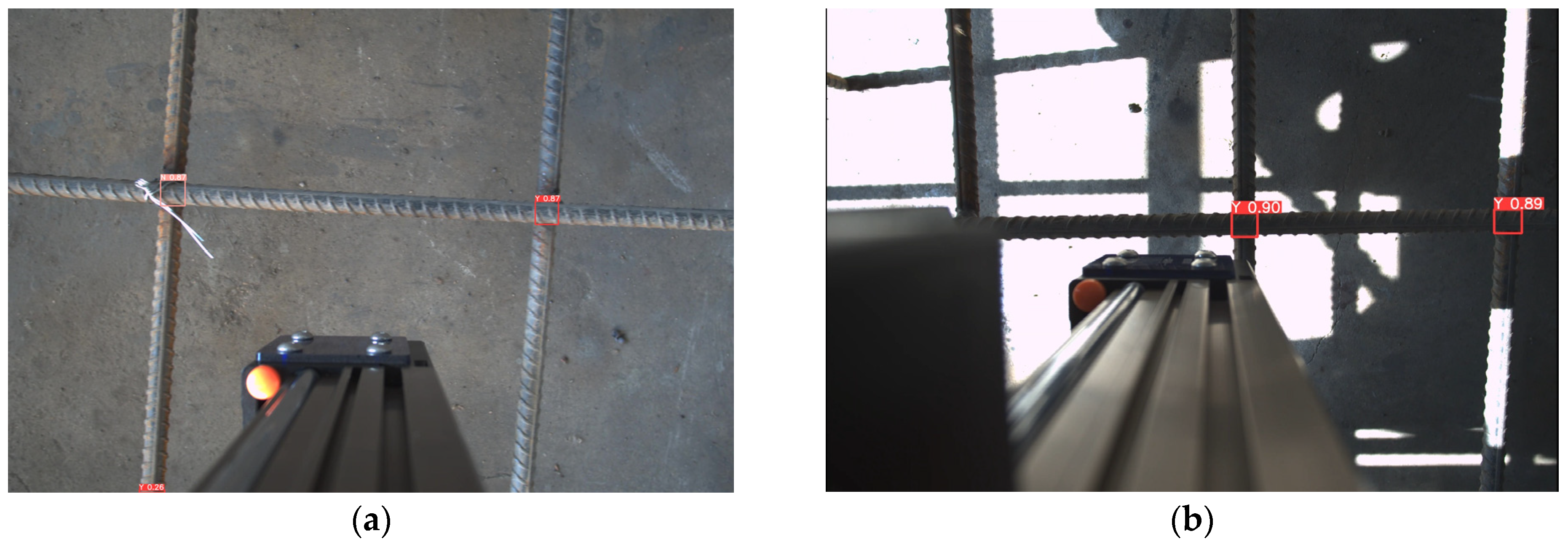
Once the automatic tying process begins, the total number of rebar intersections and the corresponding coordinate information, which are ultimately detected by the ‘dual-camera visual detection program’, are continuously sent via ROS topic communication. The visual detection program is executed in two stages. The first stage is based on the depth camera which obtains the image of the area to be tied. The trained YOLOv5 deep neural network model is used to identify the location of all rebar intersections in the field of view of the depth camera. The clustering algorithm rejects outliers and counts all the points to be tied every ten frames. After the patient receives the message to start tying, the detection result is sent. The ‘tying control program’ receives the coordinates and executes the movement to the top of the tying point.
The second stage is as follows: For each intersection point to be tied, first, a high-precision industrial camera fixed on the tying head is used to collect real-time images near the target point. Based on the same well-trained YOLOv5 deep neural network, the exact location of the target rebar intersection point and the tying status are identified. If the intersection point is not tied, the ‘data buffer and position fine-tuning program’ is used to fine-tune the coordinates in real time. After accurately converting the obtained coordinates, the system is resent to the ‘tying control program’, enabling the tying head to complete the tying process with a precision of up to 1 mm or less. If the status of the intersection point is tied, then this point is skipped.
When all the points counted by the clustering algorithm as to be tied are tied, the ‘master and navigation program’ receives this message, controls the depth camera on the PTZ to rotate to the forward direction for navigation identification, sends the walking mechanism’s movement message to the ‘tying control program’ after identification, and repeats this process to complete all the automatic tying tasks in the plane.

3.2. YOLOv5 Algorithm

The core idea of the YOLOv5 algorithm is to take the whole map as the input and divide it into several grids, combining the two steps of target determination and target recognition into one. In other words, it directly gives the location of the prediction box and the category to which the prediction box belongs in the output layer, which is suitable for the task of target detection at rebar intersection points. Compared with two-stage target detection algorithms such as the RCNN [23,24], YOLOv5 has a faster operation speed and can directly detect rebar tying intersections and obstacles at construction sites. The image from the high-precision industrial camera can replace the image segmented by the Generate Region Proposals in the two-stage target detection method. Therefore, YOLOv5 is selected as the benchmark model for this method. The YOLOv5 network consists of four parts: the input side, the backbone network, the neck network, and the output side.
The main functions of the input side are dataset enhancement and adjusting the pixel size of the rebar intersection points for images from different sources. The backbone network includes the Focus structure, the Residual module, and the SPP layer. The Focus structure first performs the slicing operation on the input image, and the subsequent Residual module implements multiscale feature extraction and feature transformation. SPP is the abbreviation for spatial pyramid pooling, which can further solve the problem of multiscale pixels at rebar intersections. The neck network consists of the Residual module, up-sampling, and multichannel information fusion operation. The purpose is to fuse the extracted semantic features with the positional features and to fuse the features of the backbone layer with those of the detection layer, which can enable the model to obtain richer feature information; the output side, also known as the head network, is used to output the prediction results.
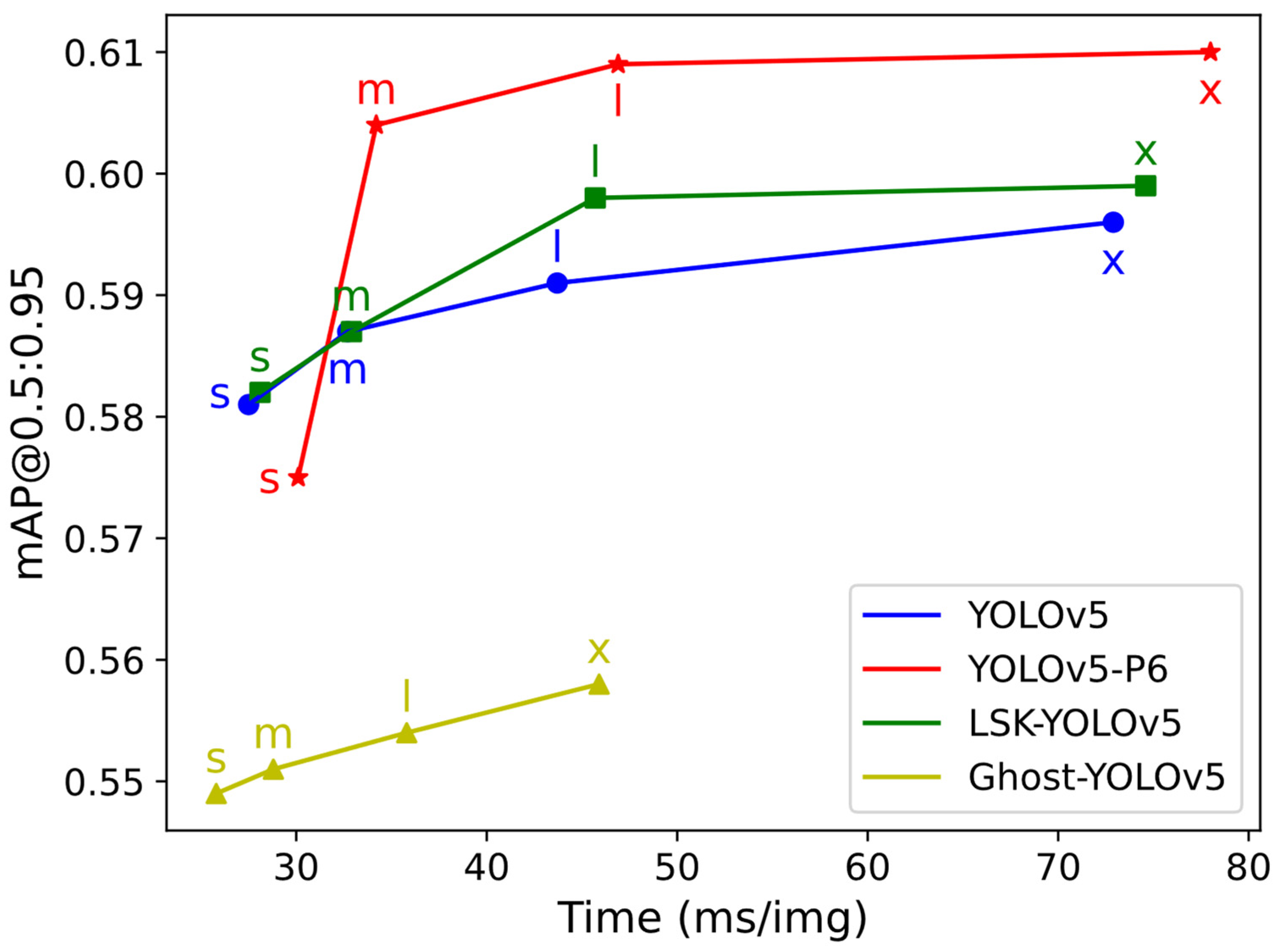
YOLOv5 developers provide several versions, and the mainstream versions are s, m, l, and x. In sequential order, the number of Residual modules in the network is increasing, the feature extraction and fusion ability is increasing, and the detection accuracy is improving; however, the corresponding time spent is also increasing. In addition, several studies have proposed improved algorithms with increased accuracy and speed based on the YOLOv5 architecture, including YOLOv5-P6 [25], LSK-YOLOv5 [26], and Ghost-YOLOv5 [27].

3.3. Clustering Algorithm

The density-based clustering algorithm (DBSCAN) [28] defines a cluster as the largest set of densely connected points. It can classify regions with sufficient density into clusters and find clusters of arbitrary shape in noisy spatial datasets. The DBSCAN algorithm categorizes data points into three classes: core points, boundary points, and noise points.
For a sample p belonging to a certain dataset D, all the sample points within its radius Eps form a set called the Eps-neighborhood NEps (p) of p, defined as shown in Equation (1), where q represents the points in dataset D that satisfy the condition where the set of points q whose distance from p is less than or equal to the radius Eps, which is the neighborhood NEps (p) of point p.
N E p s ( p ) = q D d i s t ( p , q ) E p s
(1) Core point: if the number of samples contained within the Eps neighborhood of sample c is greater than or equal to MinPts, the object is considered a core point. The set of core points is defined as shown in Equation (2), where ρ(NEps(c)) denotes the neighborhood density of sample point c, that is, the number of samples contained within the Eps neighborhood of sample c.
X c = c D ρ ( N E p s ( c ) ) M i n P t s
(2) Boundary point: if the Eps neighborhood of sample b contains fewer samples than MinPts but sample b falls within the neighborhood of core point c, then the object is a boundary point. The set of boundary points is defined as shown in Equation (3):
X b = b N E p s ( c ) c X c , ρ ( N E p s ( b ) ) M i n P t s
(3) Noise point: if sample a is neither a core point nor a boundary point, the object is a noise point. The set of noise points is defined as shown in Equation (4).
X a = a D a X c , a X b
The DBSCAN algorithm can have one or more core points inside the cluster. If there is only one core point, all the other noncore points in the cluster are in the Eps neighborhood of this core point. If there is more than one core point, then any core point in the cluster must have one other core point in its Eps neighborhood; otherwise, the two core points are not density-reachable. The set of all samples in the Eps neighborhood of these core points formed a DBSCAN clustering cluster.

3.4. Data Collection and Evaluation Metrics Overview

To verify the accuracy of the rebar-typing robot in terms of the control system and target recognition algorithm, a 6 m × 8 m rebar mesh demonstration platform was constructed at the experimental site, with rebar spacings varying from 20 cm × 20 cm to 15 cm × 15 cm, and the rebar intersection points were manually tied at random locations.

3.4.1. Data Collection

The data are collected from the experimental site and the floor, bearing platform, and bridge deck rebar photographs of 15 housing and bridge projects under construction by the China Railway Nine Bureau Group Limited. The experimental site was photographed by a D455 depth camera and an MV-CH120-10UC industrial camera. The MV-CH120-10UC industrial camera is perpendicular to the rebar surface with a photographic distance of approximately 50 cm, and there are approximately 15~25 rebar intersections in the field of view. Moreover, the diversity and generalizability of the dataset are enhanced by randomly changing the rebar position and adjusting the opening and closing of the shutters to change the indoor lighting conditions. A total of 1338 images were taken, and the images were labeled with the LabelImg labeling tool. An number of 50 images were selected as the test set. The remaining data were randomly selected with 80% being for the training set and 20% for the validation set.

3.4.2. Evaluation Metrics

To comprehensively evaluate the performance of the above models, the performance of the following five performance metrics is observed, including the Precision, Recall, mean Average Precision ([email protected], [email protected]:0.95), and time required to detect an image. Where the definitions of Precision, Recall, and mAP are shown in Equations (5)–(7):
P r e c i s i o n = T P T P + F P
R e c a l l = T P T P + F N
m A P = 1 2 ( 0 1 P ( R ) d R + 0 1 P * ( R * ) d R * )
Precision (P) is the ratio of the number of samples correctly identified by the model as belonging to the positive class (true positives, TP) to the total number of samples identified by the model as positive (including both true positives, TP, and false positives, FP). Recall (R) represents the ratio of the number of samples correctly identified by the model as belonging to the positive class (TP) to the total number of samples that actually belong to the positive class (including both true positives, TP, and false negatives, FN). The mean Average Precision (mAP) is obtained by averaging the average precision (AP) of all classes (both positive and negative). AP is the average of the precision at different Recall levels, which can be obtained by calculating the area under the P-R curve. [email protected] denotes the average precision of the two classes (positive and negative) at the IoU threshold of 0.5. [email protected]:0.95 denotes the mAP for different IoU thresholds (from 0.5 to 0.95 in intervals of 0.05), where IoU represents the ratio of the intersection area of the prediction frame with the calibration frame to the concatenation area of the prediction frame with the calibration frame.

4. Results

4.1. YOLOv5 Model Training

The training environment used Windows 10, Python 3.8, and the deep learning framework PyTorch 1.12. GPU model NVIDIA RTX3090, CUDA version 11.3.1. The network parameters were set to epochs = 3000 and a batch size = 8. The four models YOLOv5, YOLOv5-P6, LSK-YOLOv5, and Ghost-YOLOv5 are trained with the four depth parameters, s, m, l, and x, respectively. The evaluation performance metrics for the validation set of different models are shown in Table 2.
To visually represent the recognition accuracy performance of the different models, we computed the harmonic average of the Precision, Recall, and [email protected] for the different versions of each model presented in Table 2. These results are shown in Figure 8. It can be observed that the YOLOv5-P6 model outperforms the other three models.
When robots are operating at an actual construction site, they usually have high demands for detection accuracy and detection speed. Consequently, the comparison between the [email protected]:0.95 and the detection time for each model is shown in Figure 9. In this graph, the horizontal coordinate is the time required to detect an image, and the vertical coordinate is the all-class average precision ([email protected]:0.95) of the validation set.
The experimental results show that for the rebar intersection recognition task, among the four original models based on the YOLOv5 architecture and their corresponding improved algorithms, the best performance in terms of accuracy is that of YOLOv5-P6x, but it also has the longest detection time. The best performance in terms of speed is obtained with Ghost-YOLOv5s, but it exhibited the lowest detection accuracy. Overall, LSK-YOLOv5 has a slightly better performance than YOLOv5. In this work, we ultimately choose the YOLOv5-P6m model, whose mAP metric is basically consistent with that of YOLOv5-P6l and YOLOv5-P6x; this model has a much greater mAP than the other models and can thus satisfy the demand for on-site detection accuracy. Moreover, its detection speed is much greater than that of YOLOv5-P6l and YOLOv5-P6x. Therefore, in the practical application of the robot, we chose YOLOv5-P6m as the target detection model.

4.2. Combining DBSCAN Algorithm

The rebar-tying robot equipped with the trained YOLOv5-P6m model was tested on a rebar mesh demonstration platform at the experimental site. The machine frame detection range is shown in Figure 10, and there are 25 rebar intersections in the field of view.
We counted the detection results of 10 image frames captured by the depth camera, as shown in Table 3 and Figure 11. In Table 3, ‘√’ means that the intersection is detected in that frame of the image, and ‘–’ means that it is not detected in that frame of the image. We can observe that the points do not consistently appear within the machine detection range under a single detection result. This inconsistency is attributed to varying lighting conditions and machine edge occlusions encountered in the field. Therefore, the YOLOv5-P6m model exhibits fluctuations in detection results during the recognition of each image frame, resulting in missed and false detections that ultimately impact detection accuracy.
To improve detection accuracy, we further processed the detection results for every 10 frames based on the clustering algorithm before passing them to the decision layer for the walking navigation and tying tasks. The results are shown in Table 4. After excluding the three obscured points (1-1, 1-2, 2-2), the rebar intersection recognition accuracy of the 10-frame statistics reached 100%, which is a 32.5% improvement compared to the single-frame recognition result of 75.5%. This approach effectively improves the identification accuracy and reduces the fluctuations during single-frame identification.

4.3. Tying Test at the Experimental Site

After the hardware commissioning, software debugging, and training of the YOLOv5 model, the rebar-tying robot was placed on a rebar mesh demonstration platform at the experimental site. After the robot was powered up, the ROS main program and each node were started and set to the fully automatic tying mode. A depth camera and an industrial camera were used for rebar intersection point target identification. During the automatic tying process, the robot completes navigation and tying based on the rebar intersections detected by the depth camera; the industrial camera mounted near the tying head assists in the positional fine-tuning of the tying process and skips over the intersections that have already been tied.
The identification results are shown in Figure 12. The reliability and detection speed of the tying robot under different light and shadow conditions meet the tying requirements. As measured, the duration at each rebar intersection is approximately 5 s; the duration of each machine frame detection ranged from approximately 9 to 12 tying points; and the duration of the walking mechanism to the next area is approximately 12 s; therefore, an average of 6 s is needed to tie an intersection. For the 6 m × 8 m rebar mesh demonstration platform at the experimental site, the success rate of tying can reach 100%, and the total time consumed is 140 min, which is highly practical.

5. Discussion

In this paper, a comprehensive experimental validation of the developed rebar-tying robot is carried out to evaluate the accuracy and practicality of its control system and target recognition algorithm. The experimental site simulated an actual construction environment; a 6 m × 8 m rebar mesh was constructed using a 12 mm diameter rebar, and some rebar intersections were manually tied randomly. During the training and validation of the YOLOv5 model, we employed a large number of real rebar photos from the experimental site as well as from the construction projects of the China Railway Ninth Bureau. By comparing the performance of different network models in the rebar intersection target detection task, it was found that the YOLOv5-P6m model performed well in terms of both its detection accuracy and speed; thus, it was selected as the target detection model for this study. The experimental results show that the model recognizes the location of rebar intersection points accurately and can effectively differentiate between points to be tied and those already tied.
To further improve detection stability, we propose a method to combine the network detection results with the DBSCAN clustering algorithm. The experimental results show that, by analyzing the detection results for every 10 frames, the number of rebar intersection points identified is improved by 32.5% compared to that of the single-frame identification, which effectively reduces the fluctuation in the single-frame identification process and thus improves the identification accuracy.
In the robot’s tying test, we placed the robot on the rebar plane at the experimental site for the actual tying operation. The robot was able to complete the autonomous navigation and tying task according to the rebar intersection points detected by the depth camera, while the industrial camera assisted in the positional fine-tuning of the tying process. The experimental results show that the reliability and detection speed of the robot under different light and shadow conditions meet the tying requirements, and the tying time for each rebar intersection is approximately 6 s. During the 140 min experiment, the robot successfully tied all the rebar intersections at the experimental site, and the tying success rate reached 100%.
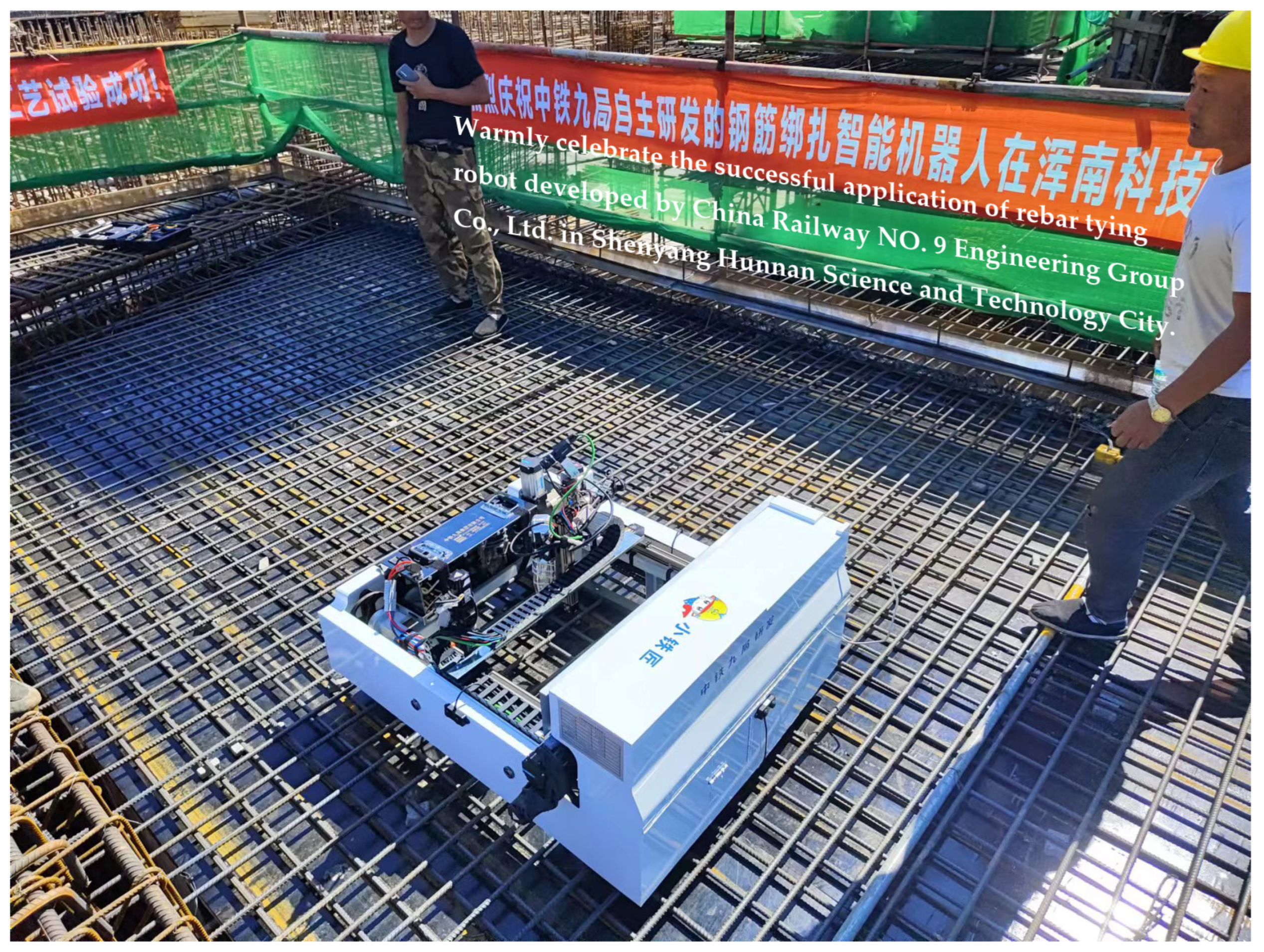
In summary, the rebar-tying robot developed in this paper has a high level of automation and intelligence and is capable of accurately identifying and tying rebar intersections in an actual construction environment. The research results are highly important for improving the construction efficiency and quality of the construction industry and simultaneously provide strong technical support and a reference for the intelligent upgrading of the construction industry. Based on the research results in this paper, the rebar-tying robot has been redesigned with a more compact industrial design for on-site applications on construction sites. It has been successfully applied in the Shenyang Hunnan Science and Technology City Phase IV project. A schematic diagram of the robot’s field application is illustrated in Figure 13, showcasing the functions of autonomously searching for working areas, autonomously planning walking routes, autonomously locating rebar intersection points, and autonomously tying.

6. Conclusions

To solve the problem of the heavy and inefficient rebar tying process in the construction industry, we independently developed a walking robot that can walk on the surface of the rebar. The robot adopts a unique stepping walk, which enables autonomous navigation operations, the autonomous positioning of rebar intersections, and the intelligent planning of tying paths on large-scale bearing platforms and bridge deck slabs under non-boundary conditions. This paper introduces the core part—the new control system based on the ROS and visual recognition technology we designed for this robot. To achieve the quick and accurate identification of the tying position and status, and solve the problem of detecting small targets at the intersections of rebars, this work proposes a two-stage recognition method in which images of an area are tied through the fusion of a depth camera and a high-precision industrial camera. A target detection module based on deep learning and clustering algorithms is designed to solve the problem of the damage to the tying head caused by inaccurate identification. The adequate experimental verification proves that the self-developed rebar-tying robot in this paper is capable of completing actual rebar tying tasks. It fills the gap and is the first small mobile rebar-tying robot with practical value in the industry, which can improve work efficiency and construction quality and provide strong technical support and a reference for intelligent upgrading in the construction industry. A related video has been uploaded at: https://www.bilibili.com/video/BV1px42127dU(accessed on 4 March 2024).
There are potential improvements in rebar-tying robots we plan to research in the future: first, because of the complexity of the construction site environment, we plan to introduce laser sensing technology combined with camera sensing to develop advanced navigation algorithms with obstacle avoidance; second, to further improve the efficiency of the tying operation, we will explore more advanced robot walking and tying path planning algorithms. These optimization measures are expected to improve our robot system’s performance.

7. Patents

Based on the research of this paper, one invention patent has been authorized.
Name: A kind of walking control system and method for a steel rebar tying robot.
Public Number: CN116225030A.
Patent Owner: China Railway NO. 9 Engineering Group Co., Ltd.
First Inventor: Ruocheng Feng.

Author Contributions

Methodology, software, investigation, data curation, visualization, writing—original draft preparation, R.F.; conceptualization, formal analysis, resources, project administration, Y.J.; supervision, writing—review and editing, T.W.; validation, writing—review and editing, H.G. All authors have read and agreed to the published version of the manuscript.

Funding

This research was funded by the National Key R&D Program of China, grant number 2022YFB2602200, and the Science and Technology Research and Development Program of China Railway Corporation Limited, grant number 2021-Major Special Projects-09.

Data Availability Statement

Publicly available datasets were generated in this study. This data can be found here: https://doi.org/10.6084/m9.figshare.25340662 (accessed on 5 March 2024).

Conflicts of Interest

Authors Ruocheng Feng and Youquan Jia were employed by the company China Railway NO. 9 Engineering Group Co., Ltd. The remaining authors declare that the research was conducted in the absence of any commercial or financial relationships that could be construed as a potential conflict of interest.

References

  1. Antwi-Afari, M.F.; Anwer, S.; Umer, W.; Mi, H.Y.; Yu, Y.T.; Moon, S.; Hossain, U. Machine learning-based identification and classification of physical fatigue levels: A novel method based on a wearable insole device. Int. J. Ind. Ergon. 2023, 93, 103404. [Google Scholar] [CrossRef]
  2. Lee, J.H.; Rhee, J. A study on the core confinement method of reinforced concrete piers. J. Korean Soc. Civ. Eng. A 2004, 24, 923–929. [Google Scholar]
  3. Umer, W.; Li, H.; Szeto, G.P.Y.; Wong, A.Y.L. Identification of biomechanical risk factors for the development of lower-back disorders during manual rebar tying. J. Constr. Eng. Manag. 2017, 143, 04016080. [Google Scholar] [CrossRef]
  4. Aires, M.D.M.; Alonso, M.L.; Gago, E.J.; Pacheco-Torres, R. Technological advances in rebar tying jobs: A comparative analysis of the associated yields and illnesses. Int. J. Civ. Eng. 2015, 13, 171–178. [Google Scholar]
  5. Oudah, F.; El-Hacha, R. Joint performance in concrete beam-column connections reinforced using sma smart material. Eng. Struct. 2017, 151, 745–760. [Google Scholar] [CrossRef]
  6. Haas, C.; Skibniewski, M.; Budny, E. Robotics in Civil Engineering. Comput. -Aided Civ. Infrastruct. Eng. 1995, 10, 371–381. [Google Scholar] [CrossRef]
  7. Buchli, J.; Giftthaler, M.; Kumar, N.; Lussi, M.; Sandy, T.; Dörfler, K.; Hack, N. Digital in situ fabrication-Challenges and opportunities for robotic in situ fabrication in architecture, construction, and beyond. Cem. Concr. Res. 2018, 112, 66–75. [Google Scholar] [CrossRef]
  8. Gharbia, M.; Chang-Richards, A.; Lu, Y.; Zhong, R.Y.; Li, H. Robotic technologies for on-site building construction: A systematic review. J. Build. Eng. 2020, 32, 101584. [Google Scholar] [CrossRef]
  9. Salim, M.; Bernold, L.E. Design-integrated process planner for rebar placement. Comput. Civil. Eng. 1995, 9, 157–167. [Google Scholar] [CrossRef]
  10. Zekavat, P.R.; Moon, S.; Bernold, L.E. Holonic construction management: Unified framework for ict-supported process control. J. Manag. Eng. 2015, 31, A4014008. [Google Scholar] [CrossRef]
  11. Iqbal, F.; Ahmed, S.; Amin, F.; Qayyum, S.; Ullah, F. Integrating BIM–IoT and Autonomous Mobile Robots for Construction Site Layout Printing. Buildings 2023, 13, 2212. [Google Scholar] [CrossRef]
  12. Zhu, A.Y.; Pauwels, P.; De Vries, B. Smart component-oriented method of construction robot coordination for prefabricated housing. Autom. Constr. 2021, 129, 103778. [Google Scholar] [CrossRef]
  13. Melenbrink, N.; Werfel, J.; Menges, A. On-site autonomous construction robots: Towards unsupervised building. Autom. Constr. 2020, 119, 103312. [Google Scholar] [CrossRef]
  14. Momeni, M.; Relefors, J.; Khatry, A.; Pettersson, L.; Papadopoulos, A.V.; Nolte, T. Automated fabrication of reinforcement cages using a robotized production cell. Autom. Constr. 2022, 133, 103990. [Google Scholar] [CrossRef]
  15. Jin, J.H.; Zhang, W.M.; Li, F.X.; Li, M.Z.; Shi, Y.L.; Guo, Z.Y.; Huang, Q. Robotic binding of rebar based on active perception and planning. Autom. Constr. 2021, 132, 103939. [Google Scholar] [CrossRef]
  16. Advanced Construction Robotics, Inc. Construction Robots [Internet]; Advanced Construction Robotics, Inc.: Allison Park, PA, USA; Available online: https://www.constructionrobots.com/ (accessed on 5 March 2024).
  17. Malavolta, I.; Lewis, G.A.; Schmerl, B.; Lago, P.; Garlan, D. Mining guidelines for architecting robotics software. J. Syst. Softw. 2021, 178, 110969. [Google Scholar] [CrossRef]
  18. Zhang, S.; Li, S.Q.; Li, Y.; Li, X.; Wang, Z.G. A visual imitation learning algorithm for the selection of robots’ grasping points. Robot. Auton. Syst. 2024, 172, 104600. [Google Scholar] [CrossRef]
  19. Romero, A.; Delgado, C.; Zanzi, L.; Li, X.; Costa-Perez, X. Oros: Online operation and orchestration of collaborative robots using 5g. IEEE Trans. Netw. Serv. Manag. 2023, 20, 4216–4230. [Google Scholar] [CrossRef]
  20. Wang, H.Y.; Ye, Z.M.; Wang, D.J.; Jiang, H.L.; Liu, P.P. Synthetic datasets for rebar instance segmentation using mask r-cnn. Buildings 2023, 13, 585. [Google Scholar] [CrossRef]
  21. Dong, G.; Zhang, L.; Xin, S. Target recognition and location of steel bar binding robot based on deep learning. Electron. Meas. Technol. 2022, 45, 35–44. (In Chinese) [Google Scholar]
  22. Yan, B.; Fan, P.; Lei, X.Y.; Liu, Z.J.; Yang, F.Z. A real-time apple targets detection method for picking robot based on improved yolov5. Remote Sens. 2021, 13, 1619. [Google Scholar] [CrossRef]
  23. Lei, M.F.; Zhang, Y.B.; Deng, E.; Ni, Y.Q.; Xiao, Y.Z.; Zhang, Y.; Zhang, J.J. Intelligent recognition of joints and fissures in tunnel faces using an improved mask region-based convolutional neural network algorithm. Comput.-Aided Civ. Infrastruct. Eng. 2023, 1–20. [Google Scholar] [CrossRef]
  24. Zhang, H.M.; Li, Z.J.; Yang, Z.S.; Zhu, C.H.; Ding, Y.H.; Li, P.C.; He, X. Detection of the corn kernel breakage rate based on an improved mask region-based convolutional neural network. Agriculture 2023, 13, 2257. [Google Scholar] [CrossRef]
  25. Huang, G.; Tran, S.N.; Bai, Q.; Alty, J. Real-time automated detection of older adults’ hand gestures in home and clinical settings. Neural Comput. Appl. 2023, 35, 8143–8156. [Google Scholar] [CrossRef] [PubMed]
  26. Li, Y.; Hou, Q.; Zheng, Z. Lsknet: Large selective kernel network for remote sensing object detection. In Proceedings of the International Conference on Computer Vision, Paris, France, 4–6 October 2023. [Google Scholar]
  27. Fan, Y.C.; Qiu, Q.L.; Hou, S.H.; Li, Y.H.; Xie, J.X.; Qin, M.Y.; Chu, F.H. Application of improved yolov5 in aerial photographing infrared vehicle detection. Electronics 2022, 11, 2344. [Google Scholar] [CrossRef]
  28. Shen, J.B.; Hao, X.P.; Liang, Z.Y.; Liu, Y.; Wang, W.G.; Shao, L. Real-time superpixel segmentation by dbscan clustering algorithm. IEEE Trans. Image Process. 2016, 25, 5933–5942. [Google Scholar] [CrossRef]
Figure 1. Rebar of the bridge deck slab.
Buildings 14 00838 g001
Figure 2. The overall system architecture diagram for this paper.
Buildings 14 00838 g002
Figure 3. Photograph of the planar rebar-tying robot.
Buildings 14 00838 g003
Figure 4. Communication between the hardware modules of the robot.
Buildings 14 00838 g004
Figure 5. Robot software design architecture.
Buildings 14 00838 g005
Figure 6. Robot control logic flowchart. (a) Schematic diagram of the navigation details; (b) Schematic diagram of the walking path.
Buildings 14 00838 g006
Figure 7. Flowchart of tying control based on dual-camera visual detection.
Buildings 14 00838 g007
Figure 8. Comparison of the performances of different models (harmonic average of the Precision, Recall, and [email protected] metrics).
Buildings 14 00838 g008
Figure 9. Comparison of the performances of different models (the [email protected]:0.95 and speed metrics; s, m, l, and x represents the four different size of networks mentioned in Section 3.2).
Buildings 14 00838 g009
Figure 10. Schematic of the machine frame detection range.
Buildings 14 00838 g010
Figure 11. Statistics of the results of identifying rebar intersections in 10-frame images.
Buildings 14 00838 g011
Figure 12. Identification of rebar intersection points under different conditions. (a) The industrial camera recognizes the position and status of the tying point; (b) The industrial camera recognizes intersection positions under light and shadow conditions; (c) The depth camera recognizes the tying range; (d) The depth camera recognizes the front.
Buildings 14 00838 g012aBuildings 14 00838 g012b
Figure 13. Schematic diagram of the robot’s field application.
Buildings 14 00838 g013
Table 1. Hardware parameters.
NameParameters
Depth cameraIntel RealSense D455 Structured Light Camera
Industrial cameraHikvision MV-CH120-10UC Industrial Camera
Camera lensComputar v0828-MPY 8 mm
Master moduleNVIDIA Jetson Xavier NX
Tying head servo motorTODE SDGA-01C12PD 24 V 100 W servo motor
Walking servo motoTODE SDGA-04C11PD 48 V 400 W servo motor
RelayJY-DAM0888 8DO 8DI relay
Switch Mode Power SupplyMEANWELL DDR-30L-5/DDR-120C-12/DDR-120C-24
Battery32AH 48 V 15-cell lithium iron phosphate battery
Table 2. Comparison of the performance metrics of different models.
ModelSizePrecisionRecall[email protected][email protected]:0.95Time/img (ms)
YOLOv5small0.9120.9690.9560.58127.5
medium0.9230.9500.9560.58732.7
large0.9200.9570.9620.59143.7
xlarge0.9150.9570.9590.59672.9
YOLOv5-P6small0.9030.9630.9640.57530.1
medium0.9240.9740.9630.60434.2
large0.9320.9620.9640.60946.9
xlarge0.9220.9790.9710.6178
LSK-YOLOv5small0.9340.9190.9580.58228.1
medium0.9150.9740.9610.58732.9
large0.9350.9560.9620.59845.7
xlarge0.9260.9490.9550.59874.6
Ghost-YOLOv5small0.9130.9430.9550.54925.8
medium0.9210.9410.9630.55128.8
large0.9320.9190.9540.55435.8
xlarge0.9390.9370.9560.55845.9
Table 3. Results of the rebar intersection recognition of each image frame.
PointFrame1Frame2Frame3Frame4Frame5Frame6Frame7Frame8Frame9Frame10Count
1-11
2-12
3-15
4-15
5-16
1-20
2-20
3-210
4-27
5-28
1-33
2-34
3-38
4-39
5-39
1-48
2-49
3-410
4-49
5-49
1-510
2-59
3-56
4-510
5-59
Count16171614181716181618
Table 4. Comparison of the number of single-frame and 10-frame overlay recognitions.
10-Frame Overlay RecognitionSingle-Frame Recognition Average
Number of rebar intersections2216.6
proportions100%75.5%
Disclaimer/Publisher’s Note: The statements, opinions and data contained in all publications are solely those of the individual author(s) and contributor(s) and not of MDPI and/or the editor(s). MDPI and/or the editor(s) disclaim responsibility for any injury to people or property resulting from any ideas, methods, instructions or products referred to in the content.

