Article

Analytical Solution for the Steady Seepage Field of a Foundation Pit in an Anisotropic Layer

1
College of Civil Engineering, Hunan University, Changsha 410082, China
2
School of Civil Engineering, Central South University, Changsha 410075, China
*
Author to whom correspondence should be addressed.
Buildings 2024, 14(4), 1055; https://doi.org/10.3390/buildings14041055
Submission received: 1 March 2024 / Revised: 29 March 2024 / Accepted: 3 April 2024 / Published: 10 April 2024
(This article belongs to the Section Building Energy, Physics, Environment, and Systems)

Abstract

:
The soil piping and drift sand phenomenon is one of the catastrophic failure forms in foundation pit excavations in coastal buildings. Presently, there is a deficiency in the theoretical research regarding the seepage fields around foundation pits, primarily due to the complexity of theoretical solutions given the difficulty in accurately describing the distribution of the groundwater’s hydraulic head in a seepage field. This study proposes an explicit analytical solution for the steady-state seepage field surrounding a foundation pit under anisotropic conditions. A numerical model, constructed with FLAC3D 7.0 software, was utilized to validate the solution presented in this study. The effects of the foundation pit’s width, the distance between the retaining wall and the impervious layer, and anisotropic seepage conditions on the total head are studied through parameter research. The study shows that the flow behavior of a foundation pit is sensitive to parameters such as the anisotropy of the soil layer and the width of the foundation pit. Further, the study also analyzes the influence of the above parameters on the exit gradient and proposes a simplified algorithm for the exit hydraulic gradient at the base of a foundation pit, which can control the error within 5%. This method makes a certain contribution to improving seepage calculations for foundation pits and is applicable to the seepage problem of anisotropic soil layers.

1. Introduction

In recent years, there has been an increase in the number of projects involving deep foundation pits that are close to water environments. For foundation pits situated near coasts or in water-rich environments, the groundwater replenishment area is remarkably close to the pit, ensuring an ample water supply. When a hydraulic gradient is present between the exterior and the interior of a foundation pit, the phenomenon of seepage will occur in the soil layers. The foundation pit will experience heightened challenges originating from pore water pressure, the movement of water, and the permeation force [1,2,3]. Therefore, numerous academic researchers have endeavored to develop a reliable theory to compute the parameters associated with seepage in foundation pits. And the main approaches applied in the groundwater seepage field are analytical and numerical methods [4,5,6,7,8,9].
Compared with numerical methods, analytical solutions for the pit seepage field are more convenient and clearer. Once the mathematical expression of the pit seepage field has been determined, the hydraulic head within the pit under different boundary conditions can be calculated very quickly, and, at the same time, the effect of related parameters, such as the pit width and the permeability coefficient of the pit seepage field, can also be explored easily. The researchers Li and Jiao [10] obtained a one-dimensional analytical formula for the negative excess pore water pressure and the effective stress inside and outside foundation pits caused by excavation unloading. Compared with a one-dimensional model, the calculation of two-dimensional seepage flow was closer to the real field condition. Liu and Li [11] and Wang and Zou [12] used the two-dimensional graphic method to formulate a calculation method for the water–earth pressure inside and outside foundation pits. Banerjee and Muleshkov [13], Bereslavskiik [14], Ming et al. [15], and Li et al. [16] used different analytical approaches, specifically adopting conformal mapping to examine various boundary-condition seepage issues related to foundation pits. Through the application of the Fourier series expansion in conjunction with the establishment of certain border conditions, Barros [2] derived an analytical solution to address the seepage of foundation pits with vertical retaining walls. On this basis, implementing anisotropic permeability, Hu [17] introduced the anisotropic permeability coefficient for the hydraulic head and advanced a solution for the seepage field considering the anisotropy of soil layer permeability. In recent years, Huang [18] derived a semi-analytical solution for a foundation pit in a permeable anisotropic soil layer by dividing the seepage field into two regular regions using the Fourier transform method. Lyu [19] analyzed the blocking mechanism of a waterproof curtain on steady-state seepage in a pressurized aquifer and used an analytical method to solve the distribution of the groundwater head during pit excavation in a pressurized aquifer under the condition of setting up a waterproof curtain. According to Darcy’s law and the seepage continuity principle, Zhang [20] and Wu [21] provided the hydraulic head solution for a circular foundation pit by dividing the seepage field of the pit into two or three regions. Yu [22] divided the soil around the foundation pit into multiple regions according to the layered conditions and proposed a series solution for the water head distribution by the separation of variables method.
However, in the research referenced above, early studies considered the seepage field around a foundation pit in its entirety, which is necessary to establish the relationship between a complex irregular boundary and a regular boundary, and in this case an explicit analytical solution cannot be obtained. Furthermore, the boundary conditions of foundation pits are too simplified for the consideration of specific parameters. In recent years, studies on the analytical solution of the foundation pit seepage field often divide the seepage field into several regions, which are connected by seepage continuity conditions or head continuity conditions. This approach overcomes the shortcomings of earlier analytical solutions. But few of the above studies considered the anisotropic permeability of the soil layer. This is not consistent with the reality.
Therefore, in this study, by dividing the seepage field of a foundation pit into three regular regions and using the idea of pattern matching to solve the steady-state seepage equation, an explicit analytical solution for the hydraulic head considering the soil layer’s anisotropic permeability is proposed. The two-dimensional steady-state seepage equation for each region is solved by applying the separated variables method according to different boundary conditions. The explicit analytical solution of the seepage field around a foundation pit is expressed in the form of a series, and the coefficients to be determined are solved according to the seepage continuity conditions between the regions. The analytical solution of the hydraulic head is verified by numerical simulation results. In addition, the influences of the foundation pit width, the anisotropy of soil permeability, and the burial depth of the retaining wall on the total head are also discussed.

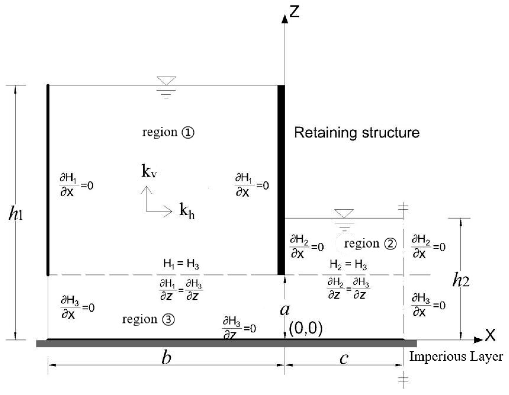
2. Problem Definition

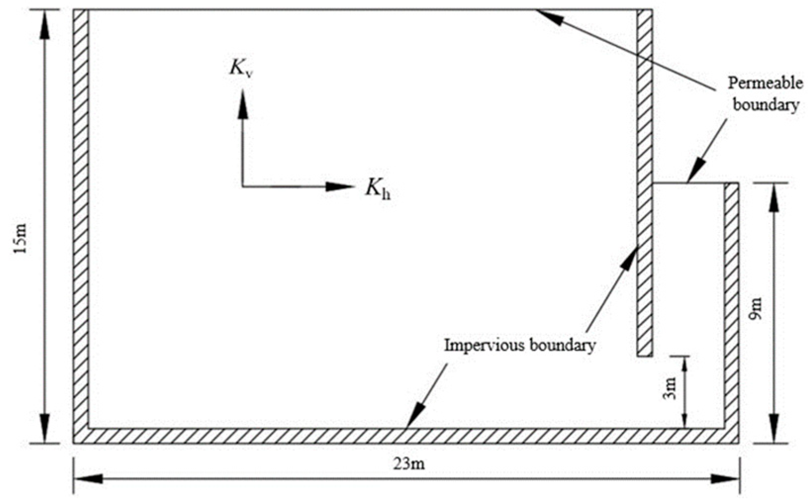
2.1. Analytical Model

For the seepage field analytical model, we made the following assumptions: the steady-state seepage field conforms to Darcy’s law, the soil layer exhibits permeable anisotropy, and beyond the influence distance of the foundation pit seepage, it can be approximated as impervious.
As depicted in Figure 1, the calculations for the geometry of the flow system under consideration are simplified by the establishment of a two-dimensional seepage model, with the foundation pit’s centerline serving as the axis. In the parameters of the foundation pit, h1 and h2 represent the exterior and interior water levels, respectively, while a signifies the distance separating the impervious layer from the retaining wall. To facilitate mathematical analysis, the seepage field is divided into three regions, while the hydraulic soil parameters across regions ①, ②, and ③ remain identical. Regions ① and ② exhibit widths of b and c, respectively, symbolizing the foundation pit’s outer and inner dimensions. The layer’s hydraulic conductivities in both the horizontal and the vertical directions are defined as kh and kv, respectively, and its hydraulic heads are labelled Hi (where i equals 1, 2, or 3). Finally, to make problem solving easier, the x-axis extends positively to the right and the y-axis extends vertically upward, as depicted in Figure 1.
The distribution of the hydraulic head in the steady-state seepage field in the soil layer with anisotropic permeability meets the following Laplace equation [23]:
k h 2 H i x 2 + k v 2 H i z 2 = 0 , i = 1 , 2 , 3
where H 1 , H 2 , and H 3 represent the total hydraulic head distribution functions of the three aquifer subareas, calculated with the soil base as a reference level.
By integrating the foundational presumption of two-dimensional foundation pit seepage with inter-regional continuity conditions, the boundary condition for region ① can be sequentially determined as follows:
H 1 | z = h 1 = h 1
H 1 x | x = b = 0 , H 1 x | x = 0 = 0
The boundary conditions of region ② are as follows:
H 2 | z = h 2 = h 2
H 2 x | x = 0 = 0 , H 2 x | x = c = 0
The boundary conditions of region ③ are as follows:
H 3 z | z = 0 = 0
H 3 x | x = b = 0 , H 3 x | x = c = 0

2.2. Analytical Solutions

Equation (1) is transformed into the form of a Laplace equation by variable substitution as follows:
2 H i u 2 + 2 H i v 2 = 0 , i = 1 , 2 , 3
where H 1 , H 2 , and H 3 are the total hydraulic head of the three aquifer subareas, and u and v are the variables corresponding to the substitution of x and z and can be expressed as follows:
u = x v = z k v k h = z α
According to the transformed boundary conditions of the region, the total water heads in regions ①, ②, and ③ can be written as the superposition of series solutions by means of the method of separation of variables as follows:
H 1 u , v = h 1 + A 10 v h 1 α + n = 1 A n sinh k n v h 1 α cos k n u , k n = n π b
H 2 u , v = h 2 + B 10 v h 2 α + m = 1 B m sinh k m v h 2 α cos k m u , k m = m π c
H 3 u , v = C 10 + i = 1 C i cosh k i v cos k i u + b , k i = i π b + c
where A 10 , B 10 , C 10 , A n , B m , and C i are undetermined coefficients that can be determined using the continuous boundary conditions at the regional interface:
H 1 | z = a = H 3 | z = a , H 1 z | z = a = H 3 z | z = a
H 2 | z = a = H 3 | z = a , H 2 z | z = a = H 3 z | z = a
According to the continuous seepage conditions between regions, the relationship between the parameters can be obtained by substituting the head solution as follows:
C 10 + i = 1 C i cosh k i a α cos k i u + b = h 1 + A 10 a h 1 α + n = 1 A n sinh k n a h 1 α cos k n u ,     ( b u < 0 ) h 2 + B 10 a h 2 α + m = 1 B m sinh k m a h 2 α cos k m u , ( 0 u c )
i = 1 C i k i sinh k i a α cos k i u + b = A 10 + n = 1 A n k n cosh k n a h 1 α cos k n u , ( b u c ) B 10 + m = 1 B m k m cosh k m a h 2 α cos k m u , ( 0 u c )
The constant terms A 10 , B 10 , and C 10 are determined with the definition of the Fourier series as follows:
A 10 = 1 b i = 1 C i sinh k i a α sin k i b
B 10 = A 10 b c
C 10 = h 1 + A 10 a h 1 α b + h 2 + B 10 a h 2 α c b + c
By multiplying both sides of Equations ( 16 ) and ( 15 ) by cos k n u , cos k m u , and cos k i ( u + b ) and integrating within the intervals ( b , 0 ) , ( 0 , c ) , and ( b , c ) , the series terms A n , B m , and C i can be determined as follows:
A n k n cosh k n a h 1 α b 2 i = 1 C i k i sinh k i a α sin k i b k i k i 2 k n 2 = 0 , ( k i k n ) A n k n cosh k n a h 1 α i = 1 C i k i sinh k i a α 1 n = 0 , ( k i = k n )
B m k m cosh k m a h 2 α c 2 + i = 1 C i k i sinh k i a α sin k i b k i k i 2 k m 2 = 0 , ( k i k m ) B m k m cosh k m a h 2 α i = 1 C i k i sinh k i a α cos k m b = 0 , ( k i = k m )
A 10 a h 1 α b c a h 2 α 1 k i sin k i b + n = 1 A n sinh k n a h 1 α sin k i b k i k i 2 k n 2 m = 1 B m sinh k m a h 2 α sin k i b k i k i 2 k m 2 C i cosh k i a α b + c 2 = h 2 h 1 1 k i sin k i b , ( k i k n , k i k m ) A 10 a h 1 α b c a h 2 α 1 k i sin k i b + n = 1 A n sinh k n a h 1 α 1 n b 2 m = 1 B m sinh k m a h 2 α sin k i b k i k i 2 k m 2 C i cosh k i a α b + c 2 = h 2 h 1 1 k i sin k i b   , ( k i = k n ) A 10 a h 1 α b c a h 2 α 1 k i sin k i b + n = 1 A n sinh k n a h 1 α sin k i b k i k i 2 k n 2 + m = 1 B m sinh k m a h 2 α cos k i b c 2 C i cosh k i a α b + c 2 = h 2 h 1 1 k i sin k i b       ,   ( k i = k m )
Based on the six equations above, the six unknowns A 10 , B 10 , C 10 , A n , B m , and C i are solved by building a matrix, which is constructed in Appendix A. By solving the matrix in Appendix A, the total hydraulic head distribution both interior and exterior to the foundation pit can be determined. It is worth noting that when utilizing MATLAB R2019a for double-precision matrix solution, an increase in the coefficient matrix EE order leads to an increment in the condition number as well. This complication can be effectively addressed using MATLAB’s multi-precision computation toolbox.

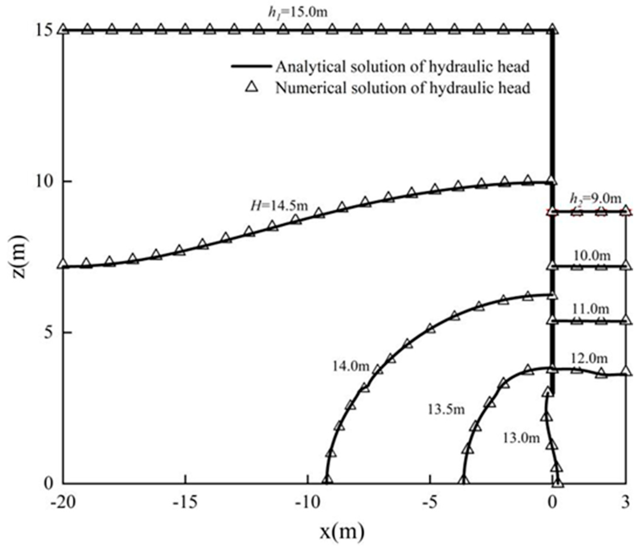
3. Verification of Proposed Solutions

To verify the accuracy of the analytical solution for the total water head, validation procedures were conducted using the finite difference software FLAC3D. The parameters of the foundation pit were assumed to be as follows: b = 20 m, c = 3 m, a   = 3 m, h 1 = 15 m, and h 2 = 9 m. The model was created in FLAC3D software as shown in Figure 2. “CONFIG fluid” was set in the command window to enter the seepage mode. The anisotropic seepage model was set up, and the command “PROPERTY” was used to assign the values of the horizontal and vertical permeability coefficients, where kv = 5 × 10⁻⁶ m/s and kh = 1 × 10⁻⁵ m/s. The retaining wall, the impervious layer, and the boundaries on the left and right sides of the model were impervious boundaries. The pore pressure was fixed to 0 at the base of the foundation pit as well as at the ground surface by using the command “FIX pp” to set the permeability boundary. The calculated pore pressure was converted to the pressure head, which was added to the position head to obtain the total head, ignoring the flow velocity. Figure 3 illustrates a comparison of the outcomes between the numerical solution and this study’s analytical solution. It is evident from Figure 3 that the total heads of the seepage field, as determined by this study’s analytical solution, are precisely aligned with the numerical solution produced by FLAC3D, thereby supporting the validity of the analytical solution presented in this paper.

4. Hydraulic Head Analysis

According to Equations (10)–(12), many factors affect the total head distribution. The parameters of the foundation pit were assumed to be as follows: b = 20 m, c = 3 m, a = 3 m, h 1 = 15 m, and h 2 = 9 m, and the anisotropic coefficient, α , was assumed to be 0.5, unless otherwise stated. Even though the newly derived solutions can yield various results, the comparison provided here pertains solely to the three parameters that have the closest relationship to the actual conditions.

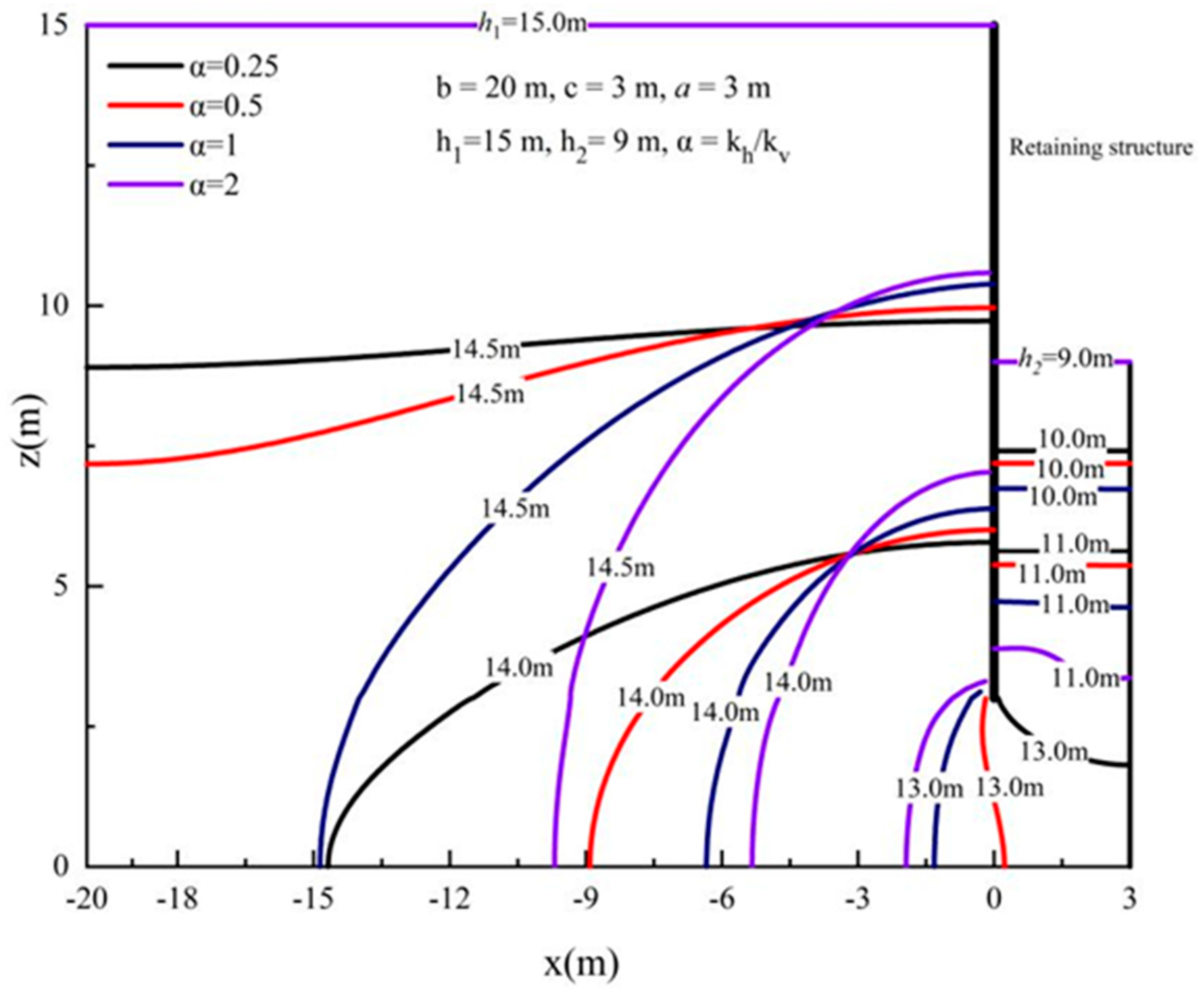
4.1. Effect of the Anisotropic Coefficient

This section considers the effect of the anisotropic permeability on the distribution of the hydraulic head. Equation (9) indicates that the anisotropic coefficient, α , is the ratio of the permeability for the horizontal and vertical directions. In this study, the anisotropic coefficient was assumed to vary from 0.25 to 2. Figure 4 illustrates that the distribution of the hydraulic head is significantly influenced by the anisotropic coefficient of seepage. This phenomenon is more significant outside the foundation pit than inside the foundation pit. Moreover, the hydraulic head inside and outside the retaining wall decreases with the increase in the anisotropic coefficient ratio,   α ; however, the opposite trend occurs approximately 3 m beyond the retaining wall. The results also illustrate that when the anisotropy coefficient increases, the decline rate of the hydraulic head distribution curve outside the retaining wall becomes faster. This presents a benefit, as, in the majority of natural deposits, the horizontal permeability coefficient typically exceeds that in the vertical direction (Rafiezadeh and Ataie-Ashtiani [24]); this shows that the seepage range of the foundation pit is smaller and safer, and this conclusion was further verified in the analysis of the exit gradient.

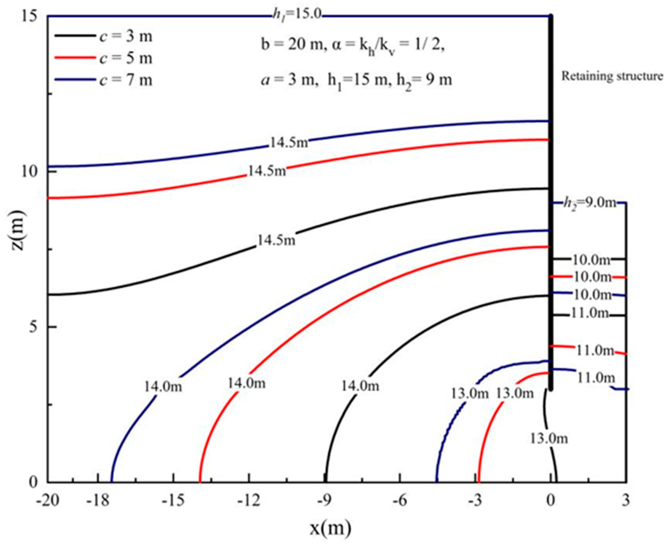
4.2. Effect of the Foundation Pit Width

The distributions of the hydraulic head versus x and z for different foundation pit widths (c = 3, 5 and 7 m) are demonstrated in Figure 5, in which the curves move to the left upper side as the width, c, of the foundation pit increases. Therefore, with an increase in the parameter c, the hydraulic head outside the retaining wall decreases, while the same trend appears inside the retaining wall. From the phenomenon, it can found that when the width of the foundation pit increases to 7 m, the high hydraulic head is mainly distributed in the upper part of the retaining wall, indicating that the influence on the seepage of the foundation pit is safer.

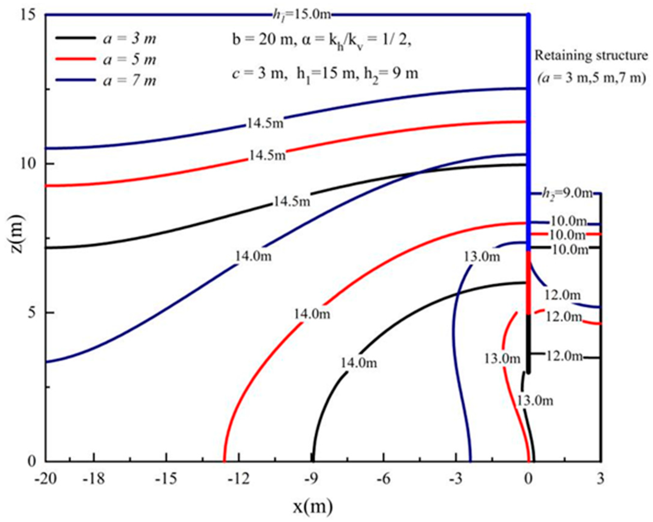
4.3. Effect of the Distance between the Retaining Wall and the Impervious Layer

In this section, the variable a represents the distance between the retaining wall and the impervious layer, which varies from 3 to 7 m. Additionally, all other necessary parameters are in accordance with those displayed in Figure 6. The distribution of the hydraulic head versus x and z with the variable a is shown in Figure 6. The groundwater seepage is significantly responsive to the burial depth of the retaining wall. The hydraulic head decreases with the increase in a, while the opposite trend appears inside the retaining wall. From Figure 6, it is also very clear that the with the decrease in the seepage path, the head difference of the excavation face increases and the risk of foundation pit seepage increases, which was verified by the exit gradient analysis.

5. Exit Gradient Analysis

The floor stability of the foundation pit with respect to potential heaving and piping failure caused by the force of hydraulic gradients applied to the soil particles at the seepage boundary is depicted in Figure 1. The occurrence of heaving, synonymous with overall upheaval, is linked to the average gradient, while localized failure due to piping is tied to the maximum gradient. Therefore, it is necessary to accurately calculate the magnitude of the exit gradient at the base of the foundation pit, i e , which is given by the following equation:
i e = 1 k z H n
where n represents the direction normal to the seepage boundary and k z = 1 means the permeability coefficient. At the base of the excavation, H = H 2 ( 0,0 ) . Additionally, i e can be compared with the results calculated for the exit gradient for one-dimensional seepage, i e 0 , which is given by the following equation:
i e 0 = h 1 h 2 h 1 + h 2 2 a

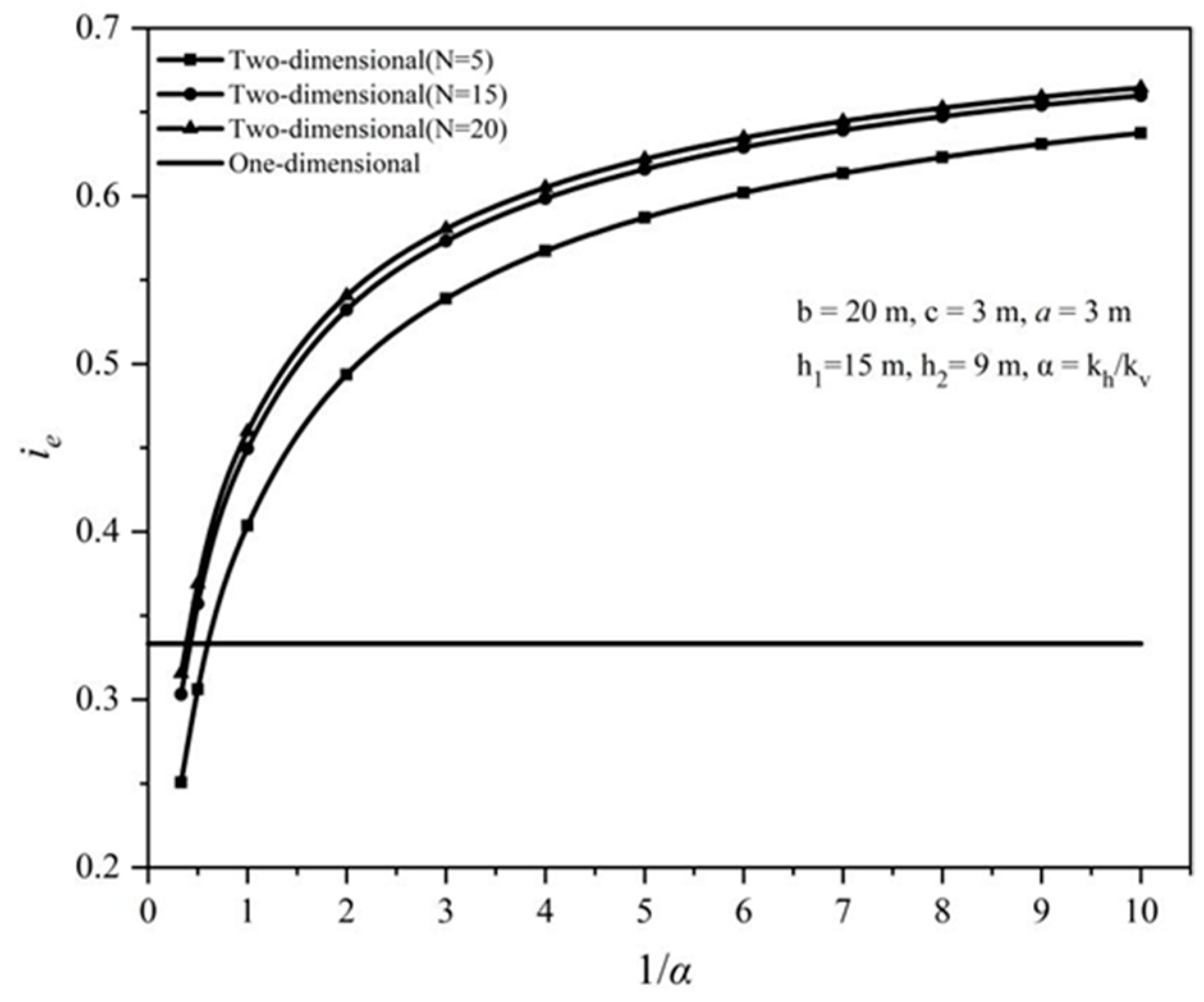
5.1. Effect of the Anisotropic Coefficient

The effects of the anisotropic coefficient, α , on i e for one-dimensional and two-dimensional seepage are shown in Figure 7. As shown in Figure 7, when the permeability of the soil is isotropic ( α = 1 ), i e is about 0.46. With the increase in 1 / α , i e increases continuously, and when the value of i e with one-dimensional seepage is constant (1/3), the effect of the permeability anisotropy on i e cannot be considered. For the case 1 / α > 1 / 2 , the i e calculated with the one-dimensional seepage model is lower than that obtained with the two-dimensional seepage model for the same permeability coefficient. Moreover, the difference between the one-dimensional flow and the two-dimensional flow is more remarkable with the increase in 1 / α .

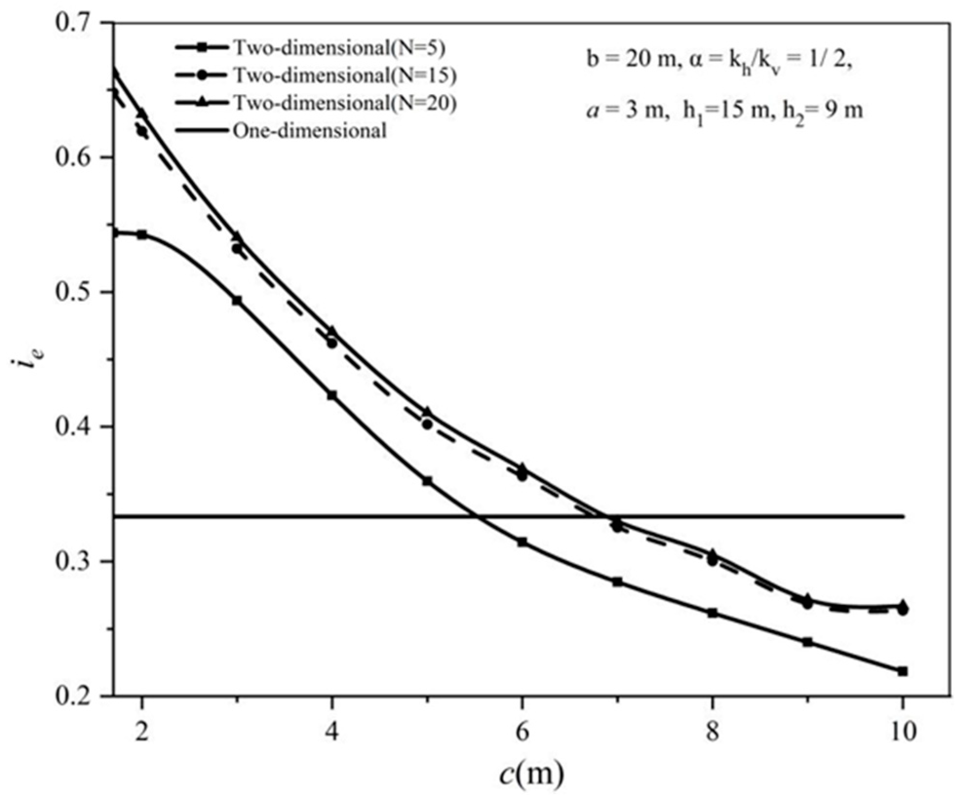
5.2. Effect of the Foundation Pit Width

The effects of the foundation pit width, c , on i e for one-dimensional and two-dimensional seepage are shown in Figure 8. As shown in Figure 8, in the case of two-dimensional seepage, when c approaches 0, i e approaches 1. With the increase in the half width of the foundation pit, c, i e decreases continuously. When c approaches infinity, i e approaches 0.26. For one-dimensional seepage, i e is one-third of the fixed value and the influence of the foundation pit width cannot be considered. When c < 5.5   m , the calculation result for one-dimensional seepage is smaller than that for two-dimensional seepage, which is unsafe. With the decrease in c , the difference between the calculation results for one-dimensional seepage and two-dimensional seepage increases.

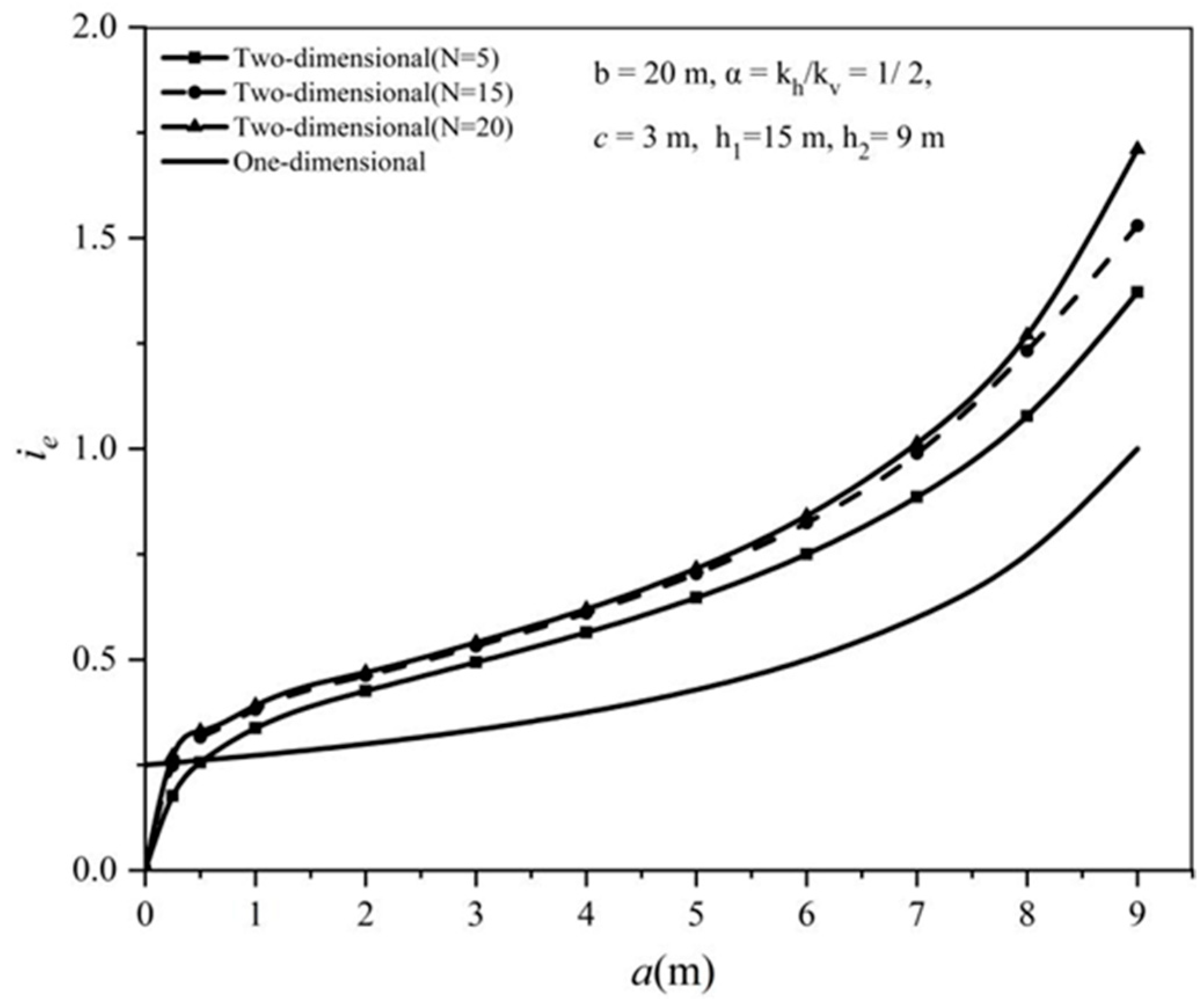
5.3. Effects of the Distance between the Retaining Wall and the Impervious Layer

The effects of the distance between the retaining wall and the impervious layer, a , on i e for one-dimensional and two-dimensional seepage are shown in Figure 9. As shown in Figure 9, with the increase in the parameter a , the exit gradient,   i e , gradually increases. In the two-dimensional seepage model, the exit gradient, i e , approaches zero, and when a increases to 9, i.e., when the bottom of the retaining wall approaches the excavation face, the value of i e is close to infinity. The difference between one-dimensional seepage and two-dimensional seepage is more remarkable with the increase in a for the same engineering parameters.

6. Discussion

Based on the analytical solution of this paper, Section 4 discussed the effects of the anisotropic coefficient, the foundation pit width, and the distance between the retaining wall and the impervious layer on the hydraulic head of the seepage field of the foundation pit. Meanwhile, to apply the analytical solution of this paper in practical engineering, Section 5 discussed the effect of these three parameters on the exit hydraulic gradient, which is associated with failure by heaving and piping.
As the width of the foundation pit increases, the head inside the retaining wall and outside the retaining wall decreases, while the exit gradient follows the same trend. This suggests that increasing the burial depth of the retaining wall can reduce the effect of seepage on pit stability. As the embedment depth of the retaining wall increases, the exit gradient decreases, which is favorable to the stability of the foundation pit against seepage. Yu [25] similarly investigated the effect of foundation pit width and distance between the retaining wall and the impervious layer on the foundation pit seepage field, and the results obtained were consistent with the conclusions of this paper. In addition, the permeability anisotropy of the soil layer is the focus of this paper. The effect of α, the ratio of the horizontal permeability coefficient to the vertical permeability coefficient, on the distribution of the hydraulic head inside and outside the pit and on the hydraulic exit gradient at the bottom of the pit is discussed in Section 4 and Section 5. With the increase in the ratio of the permeability coefficient between the horizontal and vertical directions of the soil body, the overall trend of the hydraulic headline outside the foundation pit is deflected to the inner side and the overall trend of the hydraulic headline inside the foundation pit is gently shifted downward. Huang [26] investigated the effect of the permeability anisotropy of the soil layer on the water pressure of the circular cofferdam and their conclusion is consistent with the conclusions obtained in this paper.
Furthermore, some other factors of the pit were not considered in the analytical solution of the seepage field in this paper, such as the thickness of the retaining wall and the precipitation measures. The thickness of the retaining wall can reduce the hydraulic gradient, which is helpful to prevent seepage damage to the pit. However, this paper made simplifications and did not consider the thickness of the retaining wall. Precipitation is a common measure in foundation pit excavation, but the water level distribution around the pit after precipitation is curved and will not be a constant [27], which will introduce a lot of difficulties in the analytical solution. Therefore, the seepage field of the pit, considering the thickness of the retaining wall and the precipitation measures, can be further investigated in future studies based on the analytical solution presented in this paper.

7. Conclusions

The primary achievement of this paper is to formulate an analytical solution for the seepage field surrounding a foundation pit in homogeneous and anisotropic situations. The analytical solution, substantiated through verification, aligns closely with the output from the finite difference software FLAC3D. The impact of the foundation pit’s width, the distance separating the retaining wall and the impervious layer, and the anisotropic seepage conditions on the total head have been explored by parameter analysis and discussed in detail. The primary conclusions of the study are as follows:
  • The hydraulic heads on both sides of the retaining wall for two-dimensional seepage show a curve distribution. With the increase in the anisotropic coefficient and the decrease in the foundation pit width, the hydraulic heads on both sides of the retaining wall increase continuously. With the increase in the distance between the retaining wall and the impervious layer,   a , the hydraulic heads outside the retaining wall decrease and those inside the retaining wall increase.
  • For two-dimensional seepage, the variation trend of the exit gradient, i e , is greatly affected by the size of the excavation ( α , c, and a), and with the gradual increase in the number of series terms, the influence rule and the value become more accurate. By comparing the calculation results of the first 5, 15, and 20 terms of the sum of the series, it can be concluded that the requirements for engineering precision can be met when the calculation accuracy is 20 terms.
  • The series solution presented in this paper is simple in form and high in precision, and the obtained results can be used to better observe the influence of two-dimensional geometric parameters. This method makes a certain contribution to improving seepage calculations for coastal foundation pits and can be applied to the seepage problem of layered soil.

Author Contributions

Conceptualization, Y.Z.; Methodology, Y.Z.; Software, Y.Z., X.Y. and J.Y.; Validation, C.Z. and J.Y.; Formal analysis, X.Y.; Investigation, C.Z. and J.Y.; Data curation, X.Y.; Writing—original draft, X.Y.; Writing—review & editing, X.Y.; Supervision, Y.Z. All authors have read and agreed to the published version of the manuscript.

Funding

This research received no external funding.

Data Availability Statement

The data presented in this study are available on request from the corresponding author (accurately indicate status).

Conflicts of Interest

The authors declare no conflict of interest.

Appendix A

Based on the previous equations, the series can be expressed by a matrix as follows:
E 11 0 E 13 0 E 22 E 23 E 31 E 32 E 33 A B C = 0 0 D
where E 11 , E 22 , and E 33 are all diagonal matrices:
E 11 = 1 0 0 0 α 1 0 0 0 α N
E 22 = γ 1 0 0 0 γ 2 0 0 0 γ N , γ m = k m cosh k m a h 2 α c 2
E 33 = ω 1 0 0 0 ω 2 0 0 0 ω N , ω m = cosh k i a α b + c 2
where E 23 and E 32 are square matrices of order N:
E 23 = η 11 η 12 η 1 N η 21 η 22 η 2 N η N 1 η N 2 η N N , η m i = k i sinh k i a α sin k i b k i k i 2 k m 2     , ( k i k m ) η m i = k i sinh k i a α cos k m b c 2   , ( k i = k m )
E 32 = φ 11 φ 12 φ 1 N φ 21 φ 22 φ 2 N φ N 1 φ N 2 φ N N , φ m i = sinh k m a h 2 α sin k i b k i k i 2 k m 2 , ( k i k m ) φ m i = sinh k m a h 2 α cos k i b c 2     , ( k i = k m )
where E 13 is a matrix of order (N + 1) × N and each element can be expressed as follows:
E 13 = β 01 β 02 β 0 N β 11 β 12 β 1 N β N 1 β N 2 β N N , β 0 i = 1 b sinh k i a α sin k i b
β n i = k i sinh k i a α sin k i b k i k i 2 k n 2 , ( k i k n ) β n i = k i sinh k i a α 1 n b 2     , ( k i = k n )
where E 31 is a matrix of order N × (N + 1) and each element can be expressed as follows:
E 31 = φ 10 φ 11 φ 1 N φ 20 φ 21 φ 2 N φ N 0 φ N 1 φ N N , φ i 0 = a h 1 α b c a h 2 α 1 k i sin k i b
ϕ i n = sinh k n a h 1 α sin k i b k i k i 2 k n 2 , ( k i k n ) β n i = sinh k n a h 1 α 1 b i b + c b 2         , ( k i = k n )
In addition, the matrices A, B, C, and D can be represented as follows:
A = A 10 , A 1 , A N T
B = B 1 , B N T
C = C 1 , C N T
D = d 1 , d N T , d 1 = h 2 h 1 1 k i sin k i b

References

  1. Tang, Y.Q. Prevention and treatment of deep foundation pit engineering accidents. Constr. Technol. 1997, 26, 4–5. [Google Scholar]
  2. Barros, P.L.A. A Coulomb-type solution for active earth thrust with seepage. Geotechnique 2006, 56, 159–164. [Google Scholar] [CrossRef]
  3. Barros, P.L.A.; Santos, P.J. Coefficients of active earth pressure with seepage effect. Can. Geotech. J. 2012, 49, 651–658. [Google Scholar] [CrossRef]
  4. Lee, K.K.; Leap, D.I. Application of boundary-fitted coordinate transformations to groundwater flow modeling. Transp. Porous Media 1994, 196, 297–309. [Google Scholar] [CrossRef]
  5. Lee, K.K.; Leap, D.I. Simulation of a free-surface and seepage face using boundary-fitted coordinate system method. J. Hydrol. 1997, 196, 297–309. [Google Scholar] [CrossRef]
  6. Jiang, X.L.; Zong, J.J. Three-dimensional finite element analysis of seepage fields in foundation pit. Chin. J. Geotech. Eng. 2006, 28, 564–568. [Google Scholar]
  7. Jie, Y.X.; Jie, G.Z.; Li, G.X. Seepage analysis by boundary-fitted coordinate transformation method. Chin. J. Geotech. Eng. 2004, 26, 53–56. [Google Scholar] [CrossRef]
  8. Benmebarek, N.; Benmebarek, S.; Kastner, R. Numerical studies of seepage failure of sand within a cofferdam. Comput. Geotech. 2005, 32, 264–273. [Google Scholar] [CrossRef]
  9. Luo, Z.J.; Zhang, Y.Y.; Wu, Y.X. Finite element numerical simulation of three-dimensional seepage control for deep foundation pit dewatering. J. Hydrodyn. 2008, 20, 596–602. [Google Scholar] [CrossRef]
  10. Li, H.; Jiao, J. Analytical studies of groundwater-head fluctuation in a coastal confined aquifer overlain by a semi-permeable layer with storage. Adv. Water Resour. 2001, 24, 565–573. [Google Scholar] [CrossRef]
  11. Liu, Z.Y.; Li, G.X. Computation of water and earth pressures in consideration of seepage. Ind. Constr. 2002, 32, 34–36. [Google Scholar]
  12. Wang, Z.; Zou, W.L. Earth pressure and water pressure on retaining structure. Rock Soil Mech. 2003, 24, 146–150. [Google Scholar]
  13. Banerjee, S.; Muleshkov, A. Analytical solution of steady seepage into double-walled cofferdams. J. Eng. Mech. 1992, 118, 525–539. [Google Scholar] [CrossRef]
  14. Bereslavskii, E.N. The flow of ground waters around a Zhukovskii sheet pile. J. Appl. Math. Mech. 2011, 75, 210–217. [Google Scholar] [CrossRef]
  15. Ming, H.F.; Wang, M.S.; Tan, Z.S.; Wang, X.Y. Analytical solutions for steady seepage into an underwater circular tunnel. Tunn. Undergr. Space Technol. 2010, 25, 391–396. [Google Scholar]
  16. Li, P.F.; Wang, F.; Long, Y.Y.; Zhao, X. Investigation of steady water inflow into a subsea grouted tunnel. Tunn. Undergr. Space Technol. 2018, 80, 92–102. [Google Scholar] [CrossRef]
  17. Hu, Z.; Yang, Z.X.; Wilkinson, S.P. Active Earth Pressure Acting on Retaining Wall considering Anisotropic Seepage Effect. J. Mt. Sci. 2017, 14, 1202–1211. [Google Scholar] [CrossRef]
  18. Huang, D.; Xie, K.H.; Ying, H.W. Semi-analytical solution for two-dimensional steady seepage around foundation pit in soil layer with anisotropic permeability. J. Zhejiang Univ. 2014, 48, 1802–1808. [Google Scholar]
  19. Lyu, H.M.; Shen, S.L.; Wu, Y.X.; Zhou, A.N. Calculation of groundwater head distribution with a close barrier during excavation dewatering in confined aquifer. Geosci. Front. 2020, 12, 791–803. [Google Scholar] [CrossRef]
  20. Zhang, Z.H.; Qin, W.L.; Zhang, Q.X.; Guo, Y.C. Water Control Optimization Method of Foundation Pit with Suspended Waterproof Curtain. J. Northeast. Univ. 2021, 42, 242–251. [Google Scholar]
  21. Wu, J.; Li, P.F.; Jia, J.L.; Kong, H.; Guo, C.; Guo, F. Analysis of water inflow in circular foundation pit with suspended waterproof curtain in confined aquifer. J. Beijing Jiaotong Univ. 2022, 46, 113–120. [Google Scholar]
  22. Yu, J.; Zhang, Z.Z.; He, Z.; Li, D.K. Analytical solution of two-dimensional steady-state seepage field in foundation pits in layered soils. J. Railw. Sci. Eng. 2024, 21, 194–203. [Google Scholar]
  23. Harr, M.E. Groundwater and Seepage; Dover: New York, NY, USA, 2012. [Google Scholar]
  24. Rafiezadeh, K.; Ataie-Ashtiani, B. Transient free-surface seepage in three-dimensional general anisotropic media by BEM. Eng. Anal. Bound. Elem. 2014, 46, 51–66. [Google Scholar] [CrossRef]
  25. Yu, J.; Li, D.K.; Hu, Z.W.; Zhen, J.F. Analytical solution of steady seepage field of foundation pit considering thickness of retaining wall. Chin. J. Geotech. Eng. 2023, 45, 1402–1411. [Google Scholar]
  26. Huang, J.; He, Z.; Yu, J.; Yang, X.-X. Analytical solution for steady seepage around circular cofferdam in soil layer with anisotropic permeability. Rock Soil Mech. 2023, 44, 1035–1043+1088. [Google Scholar]
  27. Guan, L.X.; Xu, C.J.; Wang, X.P.; Xia, X.Q.; Ke, W.H. Analytical solution of deformation of underlying shield tunnel caused by foundation pit excavation and dewatering. Rock Soil Mech. 2023, 44, 3241–3251. [Google Scholar]
Figure 1. Analytic model of the foundation pit seepage field.
Buildings 14 01055 g001
Figure 2. Sketch of numerical model in Flac3D.
Buildings 14 01055 g002
Figure 3. Contour map of the hydraulic heads around the foundation pit.
Buildings 14 01055 g003
Figure 4. Two−dimensional distribution of the hydraulic head versus x and z with different anisotropic coefficients.
Buildings 14 01055 g004
Figure 5. Two−dimensional distribution of the hydraulic head versus x and z with different foundation pit widths.
Buildings 14 01055 g005
Figure 6. The hydraulic head distribution with different distances between the retaining wall and the impervious layer.
Buildings 14 01055 g006
Figure 7. The effect of the anisotropic coefficient on the exit gradient at the base of the foundation pit.
Buildings 14 01055 g007
Figure 8. The effect of foundation pit width on the exit gradient at the base of the foundation pit.
Buildings 14 01055 g008
Figure 9. The effect of distance between the retaining wall and the impervious layer on the exit gradient at the base of the foundation pit.
Buildings 14 01055 g009
Disclaimer/Publisher’s Note: The statements, opinions and data contained in all publications are solely those of the individual author(s) and contributor(s) and not of MDPI and/or the editor(s). MDPI and/or the editor(s) disclaim responsibility for any injury to people or property resulting from any ideas, methods, instructions or products referred to in the content.

