Article

Seismic Retrofit of Concrete Buildings Damaged by Corrosion: A Case Study in Southern Italy

by
Michele Fabio Granata
Dipartimento di Ingegneria, Università di Palermo, 90128 Palermo, Italy
Buildings 2024, 14(4), 1064; https://doi.org/10.3390/buildings14041064
Submission received: 23 March 2024 / Revised: 3 April 2024 / Accepted: 9 April 2024 / Published: 11 April 2024

Abstract

:
A case study of a building in southern Italy, subjected to high degradation by corrosion and waiting to be assessed for retrofit interventions, is presented. The owner required modifications to the building configuration, including a new layout of the floors and retrofitting for a high level of seismic load. A double strategy of an assessment and retrofit was carried out: dynamic linear and static non-linear analyses were performed, and the results were compared. Afterwards, a global strategy of mass and stiffness redistribution was implemented together with different retrofit interventions on the foundations, columns, and beams of the framed structure, such as reinforced concrete and steel jacketing, the application of FRP plates and fabrics, new steel elements, and steel–concrete composite floors. The results of the intervention are discussed and the implications of corrosion on the structures are explored. From the results obtained, it is possible to see how the use of different techniques for strengthening and passive seismic protection strategy can allow engineers to obtain the result of structural adaptation to earthquakes with low-cost interventions. The widespread adoption of steel jackets, coupled with the construction of floors using a steel–concrete composite structure, grants a good confinement of the beam–column r.c. joints, together with the overall strengthening of the existing structure. The adoption of CFRP wrapping at the lower edge of the beams implies a limited increase in thickness and the limited interventions of partial demolition from the existing structural members. A critical review of the steel jacketing aspects in terms of bending and shear strengthening is reported by considering this technique in the form of a steel exoskeleton containing the damaged concrete structure, by confining concrete elements, and by increasing the performance for both gravitational and seismic loads.

1. Introduction

The seismic assessment of existing civil structures is a much-debated topic, especially in the case of buildings that are at the end of their service life and have a high state of degradation. In Italy, reinforced concrete (r.c.) buildings built between the 1950s and 1960s pose challenges in the evaluation of their preservation or demolition and reconstruction. In fact, these structures are located in seismic areas but were not originally designed to resist earthquakes and, therefore, the extension of their service life depends on the possibility that they are adapted to a new code of standards and, therefore, to the performance requests of these facilities. In this regard, the decision of the owner is, in many cases, to preserve the original structure with a view for sustainability, avoiding demolition and reconstruction but providing heavy structural rehabilitation interventions that pursue the objective of seismic adjustment of the structure to the levels of performance required by up-to-date Italian Codes [1,2]. When this concerns buildings with a public function, the administration requires that the level of seismic protection is as high as possible, and at the same time, contained within the costs of the available budget.
These buildings often suffer from a high state of degradation due to ageing and they present corrosion of reinforcements, an insufficient number and distribution of bars, and insufficient strength of the concrete. This means that the typical aspects of the seismic risk assessment and strengthening intervention fit into a framework of strongly corroded elements, creating not only a problem in the seismic assessment but also in the static strengthening of the gravitational loads and more generally, in the rehabilitation of degraded members.
The structural assessment of such a damaged concrete structure strongly depends on the actual level of knowledge achieved from the existing elements. In fact, the level of knowledge necessary for the structural assessment and the design of retrofit solutions for these buildings is very high, including knowledge of the geometry of reinforced concrete (r.c.) elements, quantity and distribution of reinforcements, typology of the floor, and properties of materials. All these data are always affected by significant scattering due to the original quality of materials and construction methods applied. The level of knowledge influences the accuracy of the structural model, the results of the assessment analysis, and finally, the effectiveness of the retrofit interventions designed for the seismic adaptation to the new code provisions. The assessment has to take care of the reinforcement layout as well as the lack of seismic details that are common in these cases because such existing structures were built in seismic areas prior to the introduction of seismic codes. Moreover, structural members damaged by the corrosion of reinforcements worsen the performance of existing buildings, since the seismic vulnerability is influenced by the decay of materials and by the level of reinforcement corrosion [3,4,5], up to bar debonding [6] and breaking of stirrups or reinforcements that are exposed to the atmosphere. For this reason, the decay of the structural elements plays a key role in the structural assessment, especially where the gap between capacity and demand is significant [7].
In this paper, the seismic assessment and retrofit of a concrete building located in Sicily is presented as a case study of a corroded reinforced concrete structure. A total change in the structural layout is requested due to functional reasons, that is a new destination for the offices of the Body of Civil Protection. The retrofit intervention has different peculiar characteristics because the existing structure was abandoned for many decades and had been exposed to atmospheric agents, causing highly corroded structures and a lack of intermediate floors (the original structure was conceived in support of a Belvedere square at the top, without intermediate floors). The architectural refurbishment fully changed the organization of the building elements by inserting new floors and adding a functional issue to the classical concept of seismic retrofit. For this reason, the intervention can be considered an overall restoration with the addition of new structural elements. This has forced us to conceive combined interventions in which the strategy for the seismic adaptation is coupled with the restoration of the corroded structural members and the recovery and increase in bearing capacity in a new hierarchy of structural behavior and, therefore, with an appropriate sequence and plurality of strengthening measures. The main activity was the construction of new steel–concrete composite floors, hence concrete jackets [8,9], steel jackets [10,11], and CFRP wrapping [12,13], which were integrated in the works. The overall strategy was to apply a full steel exoskeleton which contains the concrete structure in order to compensate for the seismic deficiencies due to the original concept and the additional deficiencies due to the damage of corroded r.c. elements. Particularly, the role of steel jacketing is pointed out, together with the typical aspects related to the confinement of beam–column joints of the concrete frame, as a result of the seismic assessment and retrofit intervention, with highlights on the aspects of in situ construction stages, engineering practice, and the application of seismic codes.

2. Presentation of the Case Study

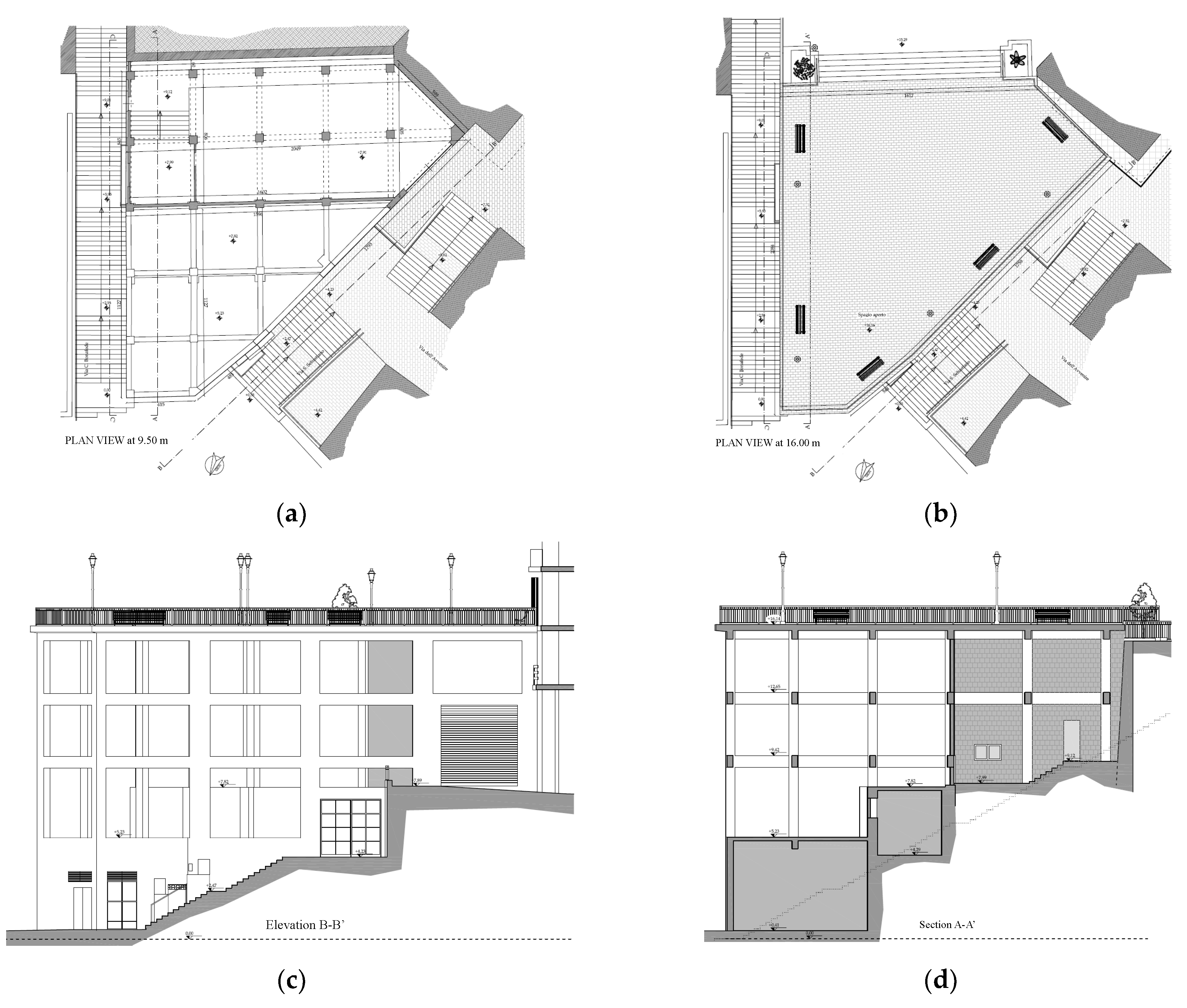
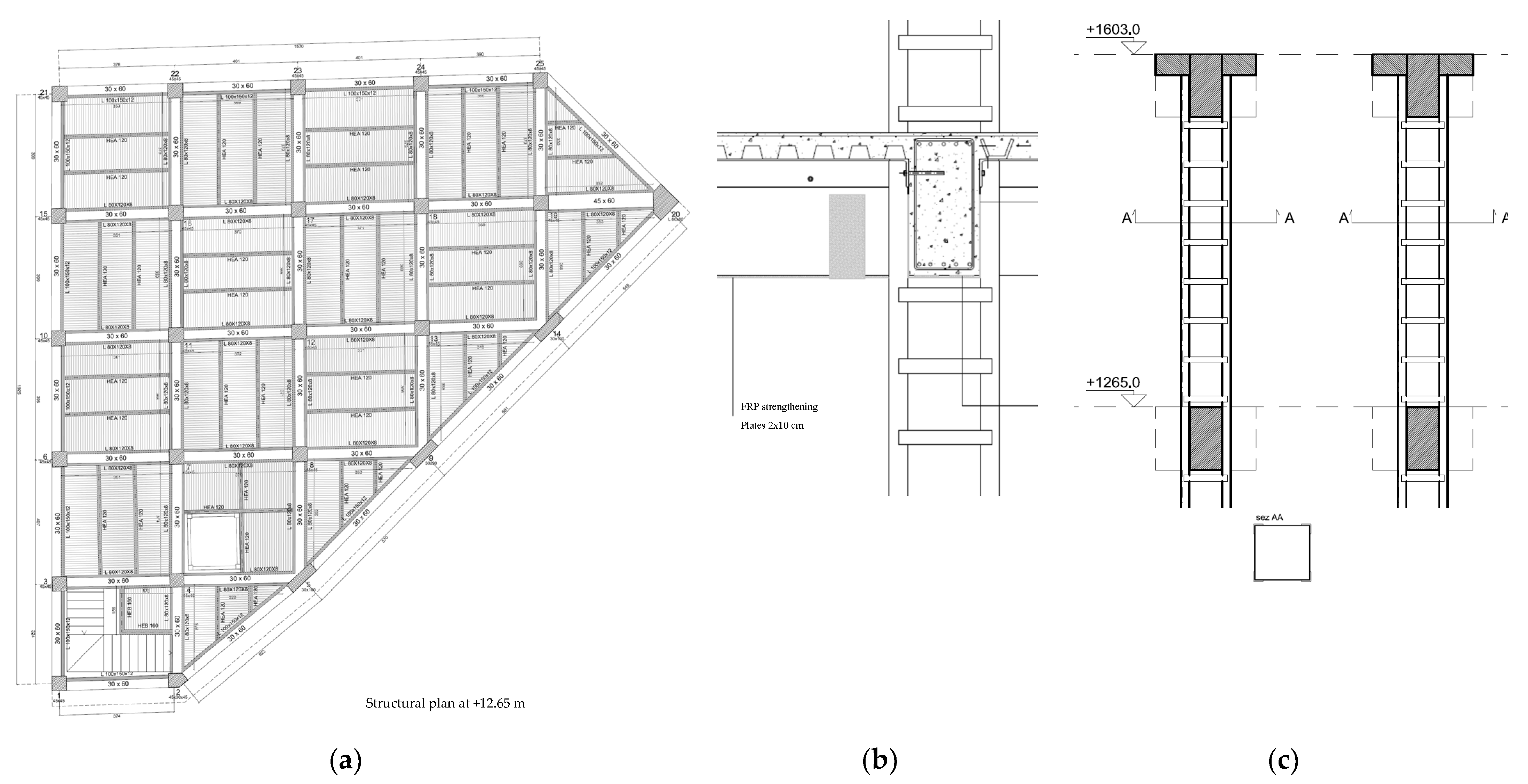
2.1. Geometry and Preliminary Investigations

The case study building is located in Sicily, southern Italy, and consists of a reinforced concrete 3D frame built on a slope in the center of a small city in the early 1960s. The building had the only function of supporting the top floor, which was a “Belvedere”, a free space adjacent to, and in continuity with, the main square of the town. The reinforced concrete frame consists of four elevations above ground and can be reached at its base by a driveway and laterally by two stairways that connect the lower part of the town with the top part where the square and the city center are located. The structure overcomes an overall height of more than 16 m. The request of the owner was to make a structural assessment of the original structure and afterwards, to change its original function, transforming the building configuration. In fact, the original configuration of this building was a 3D structural frame without intermediate floors, which supported the Belvedere square at its top. Since the urban fabric of the town is characterized by the presence of many old masonry buildings erected prior to the seismic codes, the seismic vulnerability of these buildings is very high and it is necessary to find spaces for safety during seismic or catastrophic events, even for the teams in the municipality. The square and the adjacent “Belvedere” represent the only areas of considerable size within the historic center, and they are the only areas likely to be used for the purpose of civil protection. Hence, the aim is that of transforming the structural frame which supports the Belvedere into a new building by creating three new intermediate floors. The new architectural volume is created by closing the 3D structural frame, which was also of bad architectural quality, and to create new services at the same time, including waiting areas and offices. Consequently, the seismic adaptation of the building has been conditioned by the choice to transform an open structure, originally conceived only for supporting the upper square, into a new building with internal and public functions, with a high level of seismic protection. Figure 1 shows the plans and elevation views of the structure in its original conditions.
The original structural scheme was a 3D frame with beams in the two main directions, that is, a concrete skeleton without floors and then without intermediate diaphragms, apart from the top slab. The planimetric configuration of the building is very irregular, with a quasi-triangular plan geometry having heavy consequences on the columns in terms of stress distribution, especially on the most external ones. For some columns, a strong eccentricity of the beams converging into them has been registered; furthermore, no care has been taken in confining the beam–column joints, especially for the external ones.
The irregularity of the structure is exasperated in elevation because of the presence of three levels of foundations on the slope and a heavy mass on the top due to the concrete slab of the square floor.
The materials used for construction are in line with the usual values of the time (concrete strength fc = 22 MPa and steel strength fy = 390 MPa). The conceptual design of the structure was carried out only for vertical loads, without any care for the stresses deriving from the earthquake. The overall dimension is about 20 m wide and 19 m long, the inclined side long about 23 m.

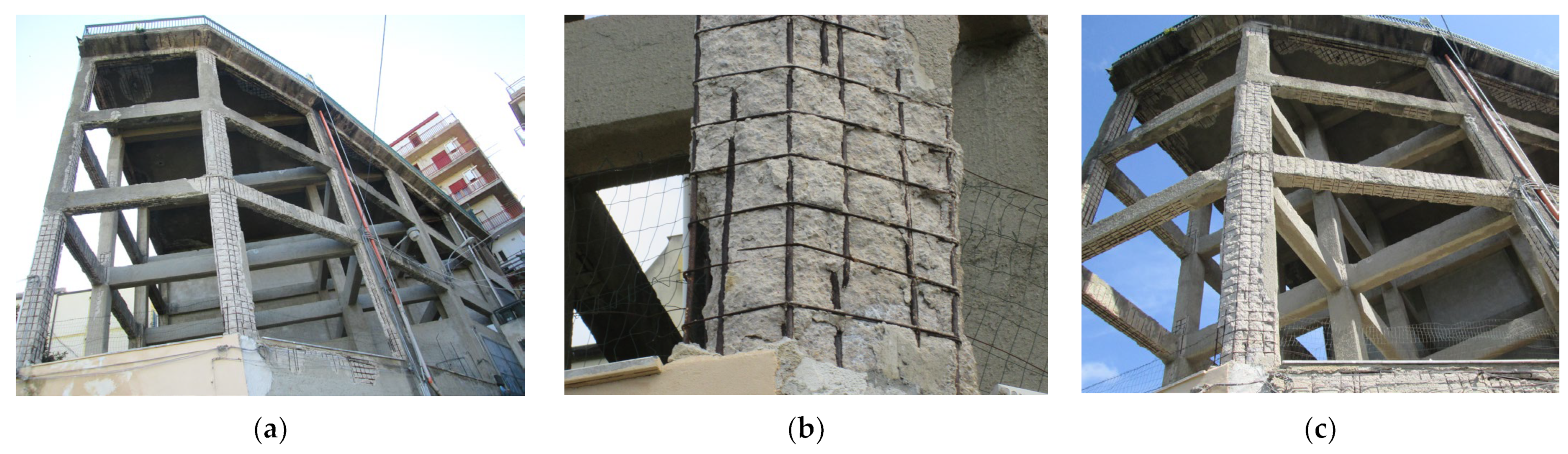
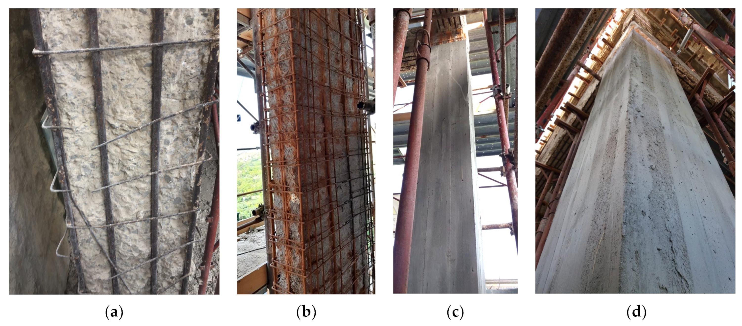
2.2. Degradation Due to Corrosion

The configuration of this building and the fact that it has remained open for decades has led to a very high state of degradation in the structures, especially the most external ones, attacked by rain and, therefore, exposed to aggressive agents. The total lack of maintenance worsened the general situation so that, after about 60 years of construction, the state of degradation in the main structures had reached a very high level. The first investigations carried out on the existing structures identified a significant degree of carbonation of concrete (consistent with the age of the structure) with spalling and deep covering detachments linked to the significant and widespread corrosion phenomena, especially at the expense of the outermost elements exposed to the atmosphere and to the wind coming from the sea. The different degradation levels found in the building facades due to wind exposure is consistent with other cases present in the literature [3].
Figure 2 shows the state of degradation in the main elements after 60 years following construction. In addition to this, the structure is characterized by several damaged areas due to previous infiltrations from the roof and by the complete absence of protective layers. This, together with the absence of any maintenance intervention, have determined the oxidation of reinforcements for many structural members, causing the concrete spalling and advanced corrosion, up to the complete degradation and breaking of stirrups and high percentages of steel mass loss in many columns and beams. On-site measurements of the bars showed corrosion up to 50% of mass loss in the most damaged longitudinal reinforcements and strong deterioration of the corroded bars.

2.3. Level of Knowledge of the Existing Structure

The level of knowledge of the existing structure is always fundamental for a structural assessment and for the design of the works to be carried out. It is conditioned by the extent and quality of the in situ surveys and by the accessibility of the structural members. In this case, the structure was easily accessible, and the distribution of concrete element geometry and reinforcement was easily detectable, so the general knowledge of the structural scheme and properties of the member cross-sections was of a good level. This is not generally the case with existing structures because the inner elements of buildings, such as the presence of flooring, finishes, and occupancy, are difficult to investigate. The complication of the knowledge in the present case study focused more on the state of decay, the low quality of the original materials, and the need to deepen the knowledge of the foundation than the geometry of elements. The uncertainty due to the local differences between elements in different areas of the structure, together with construction issues that are generally unknown to the designer of the intervention is strictly correlated to the safety factor achieved in the restored building. This is well described by the confidence factors defined by the Italian Standards [1,2], i.e., safety coefficients related to the level of knowledge reached in the assessment phase. The Italian Codes define three levels of knowledge, classifying structures with increasing levels: LC1, LC2, LC3, based on documents, on-site tests, and laboratory tests on materials, where LC1 is the lowest level of knowledge and LC3 is the best one. For achieving a high level of knowledge, the number of elements to be investigated is high, needing extensive on-site campaigns, since the Italian Codes require an affordable characterization of the structural elements and the material properties associated with the variability of them within the structural areas of the building.
The level of knowledge has an immediate consequence on the structural analysis and safety checks because each level is related to a different value of the safety factor to be used in the analyses and checks (confidence factor FC). The safety factor is applied to material strength: Level LC1 implies a confidence factor of FC = 1.35, while Level LC2 (which is the most common to be achieved with an acceptable extension of investigations and related costs) implies a confidence factor of FC = 1.20. Instead, Level LC3 implies that FC = 1, that is, the safety factor is not different from that of a new structure. This is very hard to achieve because it implies a time- and cost-consuming on-site investigation campaign together with extensive material tests. The choice of the level of knowledge actually achieved for each case has a great impact on the retrofit interventions because it conditions the value of the safety factor to be used by penalizing the strength of materials in the structural analysis and design with immediate consequences on the heaviness of retrofit and rehabilitation.
This means that as the level of knowledge increases, the confidence factor is reduced, that is, the additional safety coefficient to be applied to the material strength increases. While this implies a greater safety factor linked to a greater uncertainty of a lower level of knowledge, on the other hand, checking the same elements with higher safety coefficients implies the need to design more impactful and more expensive interventions. It follows that it is strictly necessary to optimize the level of knowledge, avoiding low levels with few in situ investigations, as this is paid for with the heaviness of the intervention. In the case study, an intermediate LC2 level was chosen, mainly due to the uncertainty of the state of degradation in the internal elements, because a higher level of knowledge would have required a careful survey of all the elements. Considering that the most significant interventions would have been carried by the most degraded elements, an intermediate degree of safety coefficient was maintained and a confidence factor FC = 1.20 was adopted.

3. Structural Model and Analyses for the Seismic Assessment

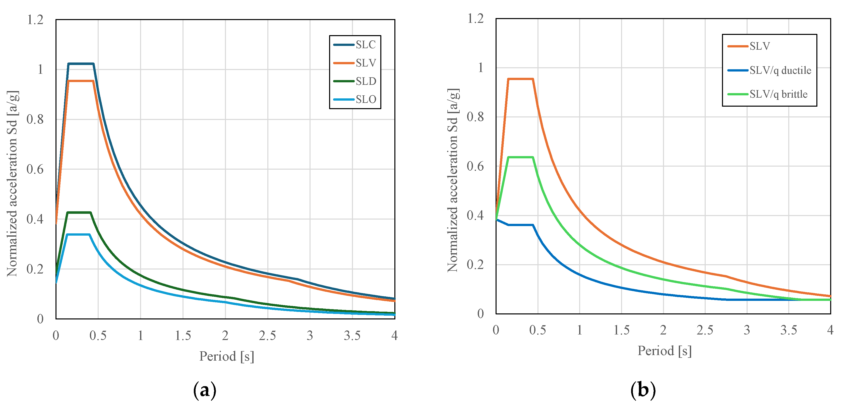
3.1. Seismic Load and Linear Dynamic Analysis

For the structural assessment of the building, different models were carried out on a FE software (PROSAP 2si v.23.6) for the analysis before and after the rehabilitation:
(a)
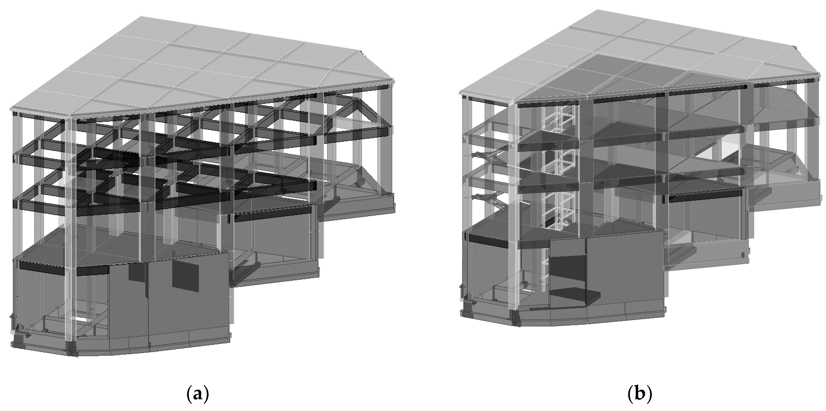
The first model, in which the building is analyzed in its original configuration of elements without corrosion (Figure 3a).
(b)
The second model, in which the building is analyzed in its original configuration of elements considering corrosion.
(c)
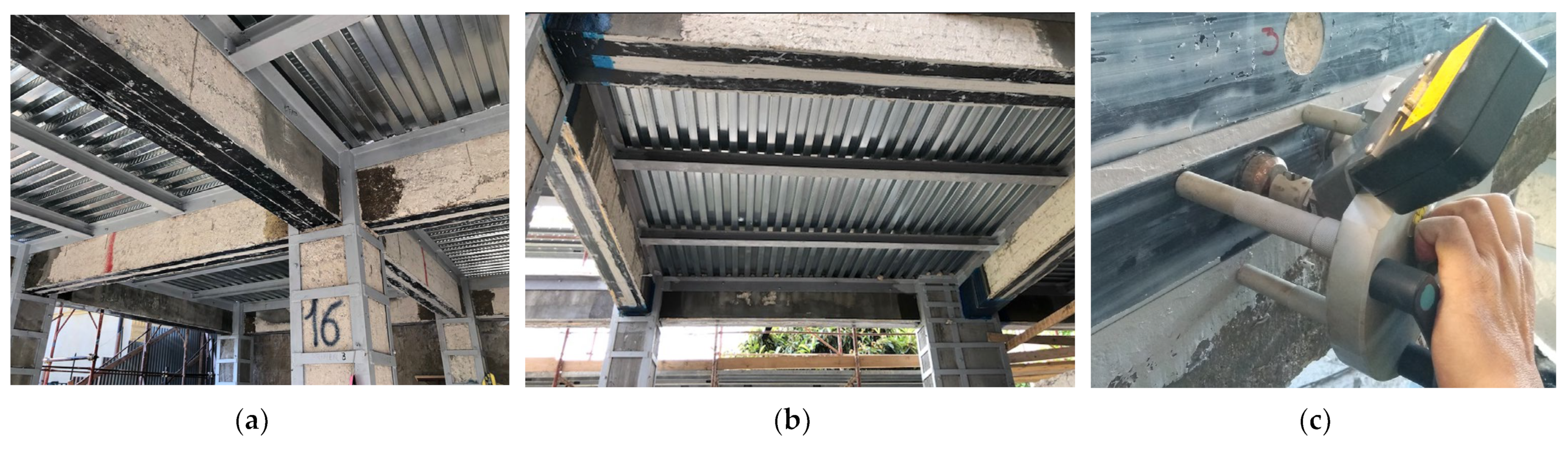
The third model, in which the building is analyzed with new intermediate floors and retrofitted structural elements (Figure 3b).
In this section, the models (a) and (b) are presented for the assessment of the structure before rehabilitation.
In the FEM representation of the structure, 2D elements (beam elements) were used for modeling the existing concrete foundation beams, columns, and floor beams. The same type of elements were used for modeling new steel columns and beams. The 3D elements (shell elements) were used to model the existing walls, the new foundation slab, and the new concrete tanks. Finally, the floors were modeled with unidirectional or bidirectional floor elements. The FE code used for analyses was PROSAP 2SI.
Figure 3. Views of the structural FE model. (a) Original configuration. (b) After rehabilitation.
Buildings 14 01064 g003
On both models, a first linear dynamic analysis was performed with the parameters shown in Table 1 and Table 2.
The design spectra for the Service Limit State and Ultimate Limit State are shown in Figure 4 for the horizontal component of an earthquake. The spectrum at ULS is obtained from the elastic spectrum, expressed in terms of accelerations, and reduced through the use of the behavior factor q. The latter should be determined with reference to the ductility actually available. The Italian Standards [1,2] provide the possibility to choose a value of the behavior factor in the range between 1.5 and 3.0, based on the regularity as well as the work rates of the materials under static actions. This can be useful for the overall analysis because trust in a limited value of ductility supplied by the existing structure can compensate, in part, for the penalization due to the confidence factor. Using a high confidence factor in a non-dissipating structure can lead to abnormal retrofit interventions that trust only in the local strength increase in elements.
In this case study, the safety check is carried out by assuming, for all the structural elements, the design forces are as following:
-
For ductile structural elements, the seismic load reduced by the behavior factor q (assumed in the range 1.5–3) is applied, checking that the stress or force in every element is less than the corresponding strength value. The authors choose the factor q in accordance with the criteria reported in the chapter 7 of the Italian Standards [2], correlating the overall ductility of the structure to the structural type, taking into account a minimum dissipative condition, that is, low ductility and irregularity in the plan and elevation of the structure. This hypothesis is supported by the following aspects: spatial frames are present in the two directions, strengthening interventions are foreseen for all the load-bearing elements, and the new construction of the missing floors is planned with composite steel–concrete structures in which the top slab thickness makes it possible to consider floors rigid in their plan. Therefore, in accordance with the Italian Standards, a behavior factor q = 2.6 was assumed.
-
For brittle structural elements, checks must instead be satisfied with the seismic load reduced by a fixed factor q = 1.5, computing the stress/force and control that it is under the corresponding strength.
For computing the strength value of forces in ductile or brittle elements, the properties of the existing materials are used, directly obtained from on-site tests, and divided by the confidence factor FC = 1.2.
Initially, the structure was modeled without considering any strengthening intervention on the individual members in order to determine the shortcomings due to both static and seismic actions.
Figure 5 shows the results of modal analysis with the first modal shapes obtained for the model before rehabilitation.
It should also be noted that, in determining the deficiencies of the original state and in the subsequent strengthening interventions, the design criteria were distinguished between the existing and newly constructed structural elements. The damage due to corrosion was considered in addition to the deficiencies found in the ideal undamaged structure, decreasing the performances of r.c. elements (i.e., the local capacity of elements in terms of bending and shear) with the obvious consequence of increasing the overall vulnerability and the demand of local strengthening.
The analysis considered degradation and corrosion by reducing the amount of effective reinforcement in terms of longitudinal bars and stirrups, especially in the outer elements where reinforcement was estimated to miss its effectiveness (in terms of corroded area or steel mass loss, which were the same). Moreover, a reduction in the concrete and steel strength to the 80% of nominal value was considered. For this reason, the overall vulnerability increased with respect to the ideal intact sections of the original configuration.
Figure 6 shows a comparison of the results of the structural checks on the two models: one with an undamaged structure and the damaged one by corrosion, in terms of N-M checks and V checks for steel of stirrups of columns. It is worth noting how deficiencies increase significantly in the damaged state, reducing the safety factor from 0.57 to 0.25 in terms of axial force and bending moment, and from 0.04 to 0.01 in the most stressed column by shear. Naturally, the number of columns with deficiencies increases significantly due to corrosion. The effect on beams is less interesting in the frame of seismic assessment, even a strong reduction in the safety factors is shown also by the outermost beams.

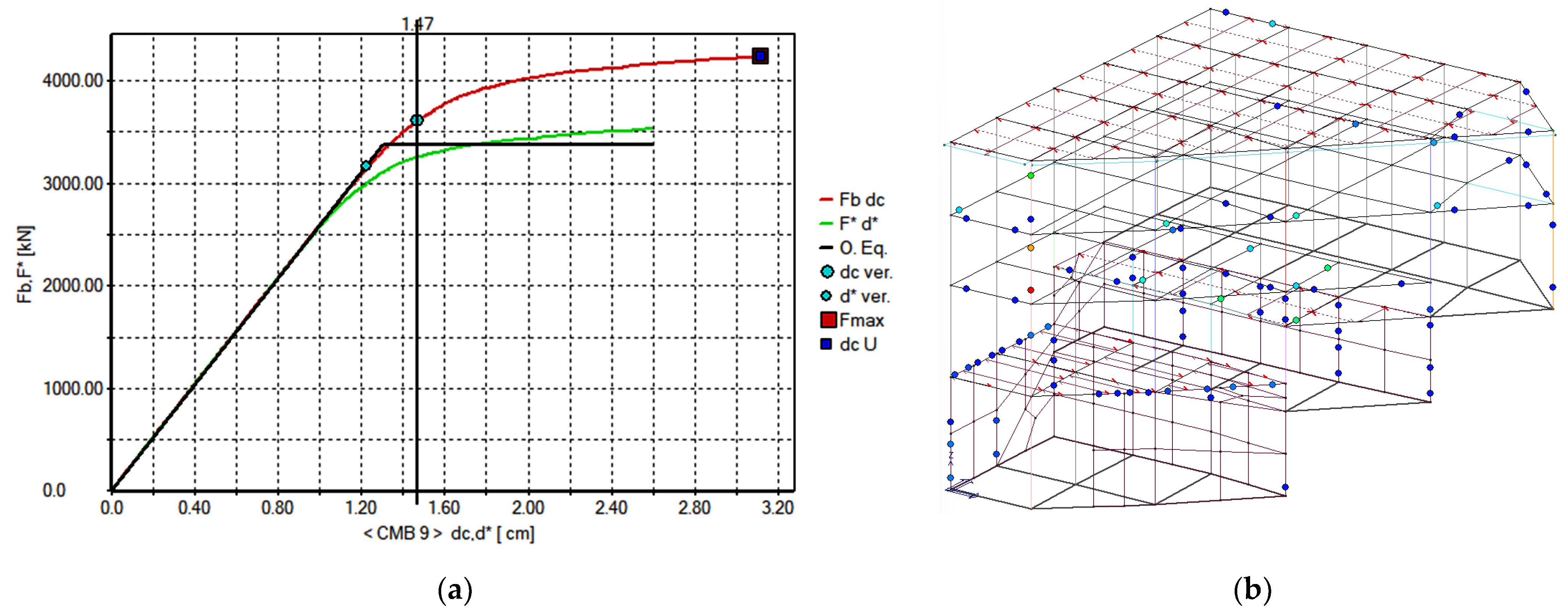
3.2. Nonlinear Static Analysis

Non-linear static analyses were carried out in order to better specify the deficiencies and to understand the most probable failure mechanisms of the structure, identifying the areas to be treated with care in the retrofit intervention and verifying the ultimate displacement and the ratio between structural demand and capacity before and after intervention.
The force profiles used for the analyses were two as follows: the first with uniform value along the building height, and the second proportional to the masses at the different levels, that is, with increasing linear distribution towards the building top. The achievement of the Ultimate Limit State is provided by a rotation of the hinge equal to 3/4 of that of collapse, as required by the Italian Standards.
Results of the pushover analysis for the building in its original conditions are summarized in Figure 7, showing the plastic hinges and the pushover curve with the value of displacement associated with the most disadvantageous collapse mechanism, which is d = 1.47 cm. The maximum shear at the base is 3601 kN.
It is worth noting that the most stressed element in the original configuration is the column on the north-west angle, which was also the most degraded one, with a high level of corrosion of longitudinal reinforcements and broken stirrups.

4. Seismic Retrofit

4.1. Strategy of Retrofitting Intervention

The conceptual approach to the seismic retrofit intervention was governed by the following issues:
(1)
The new functional configuration of the building corresponds to a new structural organization which is thought of not only for the increased vertical loads, but also for the contemporaneous reorganization of structural elements with the aim of increasing the structural regularity and decreasing the torsional effects of an earthquake on the structure, especially regarding the outermost columns. This can be considered a strategy of the first level for the global improvement through changes in geometry of elements and properties of mass and stiffness.
(2)
A strategy of the second level is that of increasing the strength of each structural element (beams and columns) and the overall structural capacity against failure with combined interventions of strength and ductility improvement.
For the first strategy, it is worth noting that the absence of intermediate floors and a heavy concrete slab on the roof, associated with three different foundation levels and the walls around the lower floors, was the cause of a high distance between the center of gravity and the center of stiffness, both in height and in plans. Hence, with the first approach, it is possible to lower the center of gravity by exploiting the realization of the new floors and bringing the center of gravity and stiffness closer to each other, greatly reducing the overall eccentricity and the torsional effects [14,15]. Furthermore, the increase in the stiffness of the columns has been studied with the aim of redistributing the base shear resulting from the earthquake between columns with careful criteria [16,17]. This was achieved with a partial demolition of some intermediate walls that had no structural function and increasing the cross-section of some columns by means of a concrete jacketing [9] associated with a steel jacketing [10]. This permits a switch from a local strengthening strategy of single elements to a global strategy on the whole structure through a widespread reinforcement intervention [11].
It follows the idea of transforming the strengthening intervention into the realization of a steel exoskeleton, understood as a steel skeleton outside the concrete elements but containing them and confining them. This is, however, all inside the building, without the need for external elements to the volume of the building of support or bracing.
In order to analyze the implementation phases and the structural aspects related to the intervention, several aspects will be examined in sequence: the rehabilitation of structures degraded by corrosion and the concrete jacketing of cross-sections, the exoskeleton and the steel jacketing of the columns together with the construction of the new composite steel–concrete floors, and finally, the local strengthening of beams towards bending and shear through the use of CFRP wrapping.

4.2. Aspects Related to Degradation and Corrosion: Concrete Jacketing of Elements

The corrosion of reinforcements reached different levels in structural elements, resulting in the spalling of the concrete and the breaking of the stirrups or highly reduced areas in longitudinal rebar for the most degraded elements, while in other cases, only a reduction in the effectiveness of the reinforcement area occurred.
The different levels of corrosion leads to several consequences for the structural element:
(1)
If the level of corrosion is less than 10% and there has been no degradation or cracking of the concrete cover, the reinforcement may be considered still partially effective, with a homogeneous reduction in the steel areas, considering that the hooks guarantee the bar anchoring at the ends, the bars being plain and not ribbed.
(2)
If the corrosion level exceeds 10% and surface concrete detachment or cracking occurs, then the reduction in the effectiveness of the bars must be greater because it is possible that the bond is no longer guaranteed by the hooked ends, so bending and shear strength is compromised and a strong reduction in the effectiveness of the rebar must be taken into account (in the present case it was considered 50% of area reduction for stirrups and longitudinal bars);
(3)
In the elements where the bars are uncovered, the concrete is deteriorated, stirrups are broken and longitudinal bars strongly corroded, the contribution of the original reinforcement has been neglected and new reinforcements have been integrated into the repaired element before the successive strengthening in order to restore the original section of the structural member.
These considerations derive from the studies in the literature on different levels of corrosion [18]. When up to 10% of mass loss occurs, the effect is mainly that of bond loss but not of capacity reduction [19]; when over 10% and up to 50% of mass loss occurs, a significant influence on the behavior of the degraded element is considered, while beyond this level, the corrosion drastically reduces the capacity of the element [6]. These considerations are generally made in the literature for ribbed bars, but in the case of smooth bars there is not the same number of studies, so there is greater uncertainty among authors. Some studies [20,21] indicated that the presence of hooks at the ends of the bars in the presence of confinement by the concrete cover can ensure bar anchoring until the yield of the steel in the hook areas. This assumption has been taken into consideration here for elements without cover detachment, neglecting the bond and, therefore, bar anchoring for higher levels of degradation.
This led to a different treatment of the problem, particularly for the most degraded columns and beams. The high level of corrosion of the outermost structural elements exposed to the atmospheric agents requires the adoption of local interventions because the minimum essential quantity of reinforcement in the element, even for static loads, was often compromised by corrosion and, therefore, was insufficient, so that the intervention with an increase in reinforcement against bending and shear was unavoidable for static requirements. Since the elements with greater oxidation are also generally the ones most stressed by seismic actions, the influence of corrosion on the retrofit intervention assumes a very significant role, which cannot be faced through a simple restoration of the original section via thixotropic mortars and local reinforcement replacements, considering also the debonding of original reinforcements consequential to corrosion and concrete damage.
For what can be seen above, in the case (1) of a low corrosion level, no concrete jacketing was applied; for the case (2) of the less damaged elements, only a reorganization of the longitudinal reinforcements was carried out, with the substitution of the stirrups and the reconstitution of the cross-section with thrown mortar to trowel. For the case (3), concerning the most degraded elements, new longitudinal reinforcements were integrated, and the stirrups were completely substituted. Afterward, a casting of pourable mortar was carried out inside the specially prepared formwork, the mortar thicknesses for jacketing being higher than in the previous case. Figure 8 shows the concrete jacketing of a degraded column with the integration of reinforcements and the mortar casting.
The thixotropic mortar used for concrete jacketing has a resistance of fmk = 40 MPa and an elastic modulus, Em = 28,000 MPa, and has been applied following a one-component cement passivating on the old reinforcements. The concrete of the new slabs has a class of C25/30, that is a compressive strength of fck = 25 MPa, while the new reinforcement has a steel grade B450C, that is a yielding strength of fyk = 450 MPa
It should be noted that the concrete jacketing used in this case is not intended as a method of strengthening as can be found in the literature [8,9,22,23], but simply as a restoration of the original condition of the cross-sections of the elements, that is a reduction in the effects of corrosion degradation. Of course, the contribution of confinement due to concrete jacketing is neglected, although the new section benefits from this in terms of bearing capacity. In fact, the shoring of the structures allows the transfer of loads, even the permanent ones, on the modified cross-section, so that the jacket, which generally remains discharged and constitutes an external strengthening layer, this time, is understood as a part of the resistant cross-section. In order to avoid a too-marked gap between the strength of the internal concrete and that of the external mortar, a reinforcement mortar with an elastic modulus and strength compatible with the original quality of the concrete, was chosen.

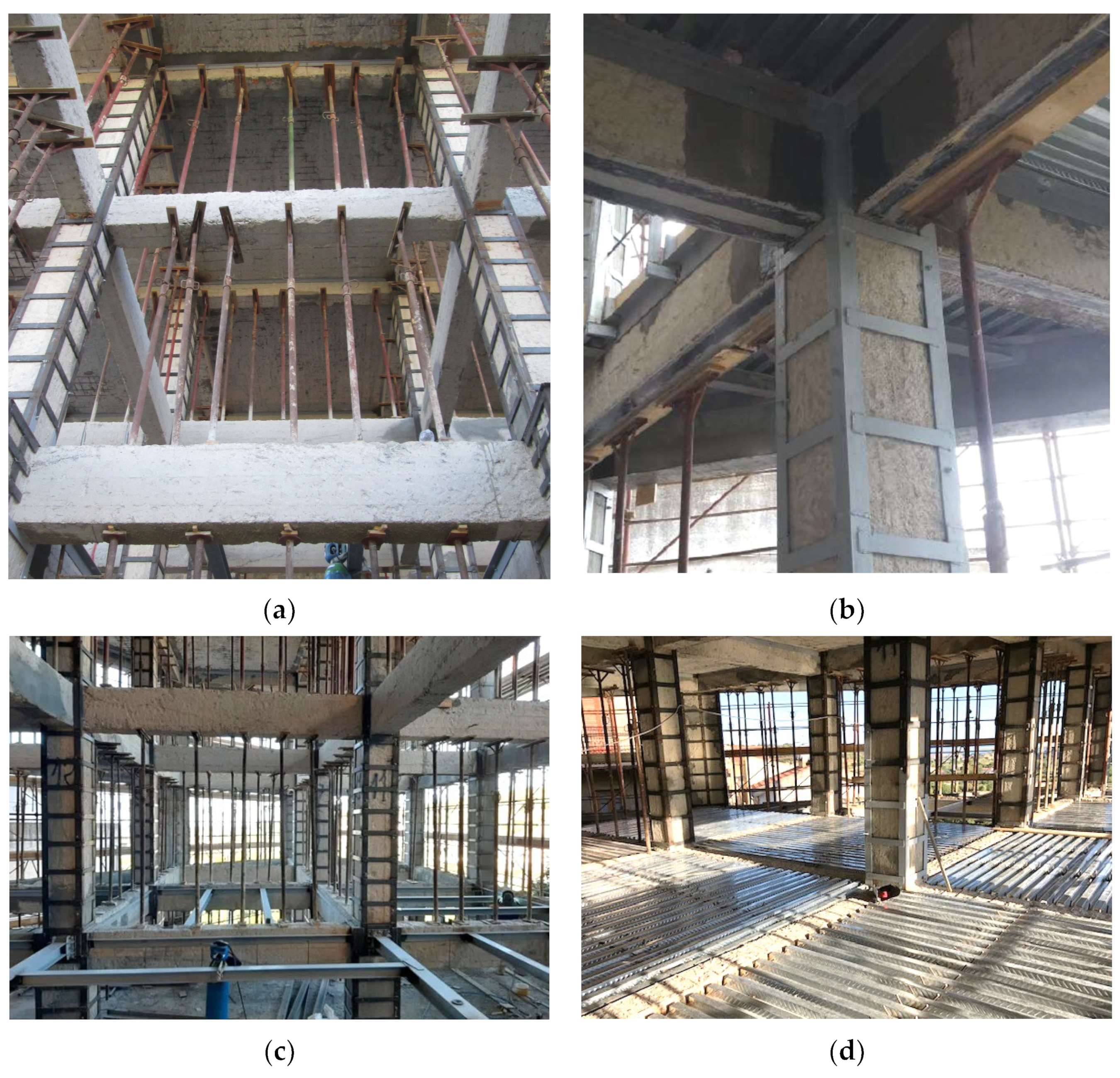
4.3. Strengthening Interventions: Steel Exoskeleton

The main strengthening intervention is carried out through steel jacketing. The assumption is that the new steel elements cooperate with the reinforced concrete section against bending and shear, i.e., considering an effective steel–concrete composite section. This assumption can be believed to be true because the steel elements of new floors confine the beam–column joint with a full connection between the steel strengthening elements of the columns and those of the beams, composing a structural steel exoskeleton to the existing concrete frame. In this way, steel jacketing of columns cooperates with the steel strengthening elements at the upper edge of the concrete beams, while local strengthening of the beams to positive bending and shear is achieved through Fiber Reinforced Polymer (FRP) wrapping both with carbon fiber plates and fabrics [13].
The lack of intermediate floors in the original configuration of the structure makes it possible to strengthen the columns with continuity in the joints. This is uncommon in existing buildings because, generally, the presence of intermediate floors makes it difficult to connect the reinforcing elements of steel jacketing to the node, which are the collars at the ends of the column beneath and above the beam-to-column connection. For this reason, in the literature, the contribution to flexure of steel jacketing is often considered low and even disregarded by the Italian Codes [2]. In contrast, the continuity of the strengthening steel elements within the joint, together with the connection with the horizontal steel elements of the floors, allowed, in this case, a good confinement of the columns and beam-to-column joints. The connection between the concrete and steel completed the cooperation in the resistance mechanism, with a concept of composite steel–concrete section of elements (Figure 9), especially for internal nodes. External nodes were confined on the free sides by steel plates and strengthened against bending in continuity within the node, with jackets anchored at the base of columns in the foundation and on the reinforced concrete slab present on the roof. The same result could not be achieved through the method of confinement by CFRP fabrics around the columns, because the deficiencies were too high to be overcome with wrapping only [24].
As reported by Campione [25], Eurocode 8 [26] considers the increase in the load-carrying capacity of the strengthened r.c. column to be a result of concrete confinement by steel angles and battens, because the load carried out by the steel angles is not included in the load-carrying capacity of the strengthened column. In this case, the load carried out by the core of cross-section depends only on the increased compressive strength of confined concrete fcc, apart the increased strength in shear due to battens. This is the choice made by the Italian Codes. By contrast, through Eurocode 4 [27], it is possible to consider the strengthened r.c. column with steel battens and angles as a composite column. In this case, the load-carrying capacity of a strengthened member is the sum of the contribution of the unconfined concrete core and steel angles together with the yielding of longitudinal bars.
Among the different studies in the literature, based on experimental campaigns, most deal with the load carrying capacity in terms of the total axial force of the strengthened column considered with confinement with the contribution of the load on the angles or not, depending on the steel cage configuration. Other experimental studies explicitly consider the eccentric load, that is the same of a bending moment in the presence of pre-load, also with cyclic loads in the presence of column collars in the joint for fixing the angles at the ends [28,29]. When steel collars are not considered, other studies [10] introduce the contribution of friction between steel angles and concrete column formulating analytical methods for the definition of the N-M domains of strengthened columns. Other studies in this field [30] confirm that the flexural contribution can be taken into account when the anchoring plates are present at the ends of the column or a mortar is interposed between the angles and concrete, or in any case, if friction occurs that reduces the sliding between the steel cage and the concrete section in order to define a steel–concrete composite cross-section as an all-in-one resistant element. In the author’s opinion, this is a more realistic assumption of the actual behavior of the strengthened column and in the present case, the evaluation of the resistance is made with this assumption.
If the anchorage plates of collars are not considered, the minimum value of resistance of the strengthened column in the Ultimate Limit State can be obtained from the studies provided by Campione et al. [10,25], taken as the minimum values of the bending capacity and the load-carrying capacity and compared to the demand values that the seismic analysis provided through the FE model. The additional strength contribution, due to the anchorage plates of angles at the ends, can be taken as an overstrength factor, although this prudential judgement refers only to the provisions of the Italian Codes but is not strictly necessary. In the author’s opinion, the fact that the steel cage could not provide an increase in the bending capacity of the reinforced column was an unrealistic and penalizing assumption that is not justified in the scientific literature. By contrast, it should be considered under the condition that at least partial resistance to sliding between steel and concrete is guaranteed, and that buckling phenomena in the compressed elements are not produced. The spacing of battens in the present case is in the range 400–500 mm along columns while steel plates width is 60–80 mm and thickness 6–8 mm. Steel of type S275JR was used with yielding strength fyk = 275 MPa.
In the present case, a diffuse connection of angles was applied through shear studs with the concrete in order to obtain an effective compound section along the column and the beam to counteract any sliding between the steel member and concrete. Although this connection is not considered strictly necessary in the literature, it approaches the behavior of the cross-section to the composite one according to Eurocode 4, which can be considered effective if the friction or the base plate only are not sufficient to ensure this behavior. In fact, Garzon Roca et al. [31] specify that the bending behavior of the steel jacketing can be taken into account according to the predictions of the composite sections of Eurocode 4 when the sliding between the steel and concrete has been limited and the element resists the base movement with the maintenance of the section with a linear distribution of the deformations, as also assumed in the works of Campione et al. [10] and Li et al. [32]. In this case, the behavior of the steel cage takes into account both the contribution of concrete, and the confinement and the strengthening of the section as in classic retrofitting through steel plating. Other studies present the same approach also in the case of strengthening solutions with angles and pre-tensioned ribbons [33].
An important aspect related to the type of intervention is the change of geometry that the structural elements and the columns in particular undergo when they are coupled to the steel cage. The steel–concrete composite section changes not only its strength, as is generally considered in the retrofit intervention, but also its stiffness, that is the different distribution of angles and battens, coupled to the r.c. jacketing of some columns, which leads to new values and distributions of bending and shear stiffness. Consequently, it is essential to assess the demand in terms of internal forces for each member on the basis of the analysis carried out on the structural model with the actual stiffnesses, that is including the effect of strengthened beams and columns with the actual geometry and stiffness.
Regardless of the increased level of strength obtained in each member, from a global point of view, an increase in structural ductility can be obtained with respect to the original configuration, avoiding brittle local failure mechanisms and exploiting the joints of the steel elements. The global result is confirmed by the pushover analyses seen above, for which an increment of final displacement and base shear is obtained after the retrofit intervention. An essential feature of the intervention carried out in this case is that the low original strength of concrete did not allow a significant strength improvement attributable to confinement when the spacing of the battens decreased. This is because the concrete of the columns and nodes, in the ultimate conditions, tends to crack so much that it crumbles inside the steel cage, transferring the load-bearing capacity almost entirely to the steel structures. Therefore, if the stability condition of the steel structures of this exoskeleton is satisfied, which is the basic criterion at the Ultimate Limit State as considered by Cirtek [34] and Campione [25], then the overall ductility is entrusted to the performance of the steel skeleton, and the dissipative capacity of the structure considerably increases compared to the original configuration. In the present case study, this condition is proven to be satisfied by the recommendations of Eurocode 4 [27] and Cirtek [34], and by the strong advantage taken by the continuity of steel angles in the node and the direct connection between the strengthening elements of the columns, those of the beams, and those constituting the new floors. Moreover, these elements also cooperate to fix the CFRP plates and fabrics at the ends of the beams, avoiding the early debonding of the fiber reinforcements, in the view of mutual cooperation and the integration of interventions.
The negative moments in the end areas of the beam were addressed through the upper plating and the presence of new floors made of steel–concrete composite structure. This means that the additional steel plates and additional negative-moment reinforcements have been inserted into the joint areas, taking advantage of the profile assembling that surrounds the slab fields and that constitute an upper strengthening of the beam, before casting the concrete slab over the corrugated sheet, which also slightly enlarged the beams in the upper side. Figure 10 shows the steel jackets of columns and the connection with the steel and concrete elements of new floors as well as a typical plan of a new floor. The welded connections of horizontal steel profiles which support the steel structure of the floor cooperate with the joint confinement, while the upper steel profiles become an upper strengthening of concrete beams to flexure and shear, the steel profiles being connected by studs to the beams at the upper edges.
Another important aspect due to the peculiarity of the building is that the columns would take on themselves the new load induced by the intermediate floors when they were already reinforced by the steel jacket, with the cross-sections of elements already improved. In fact, through an appropriate system of shoring and construction of intermediate floors for distinct and subsequent stages, after the strengthening of all the columns has been carried out, columns are loaded by distributing the gravitational actions to the strengthened columns. In this way, the distribution of axial forces and bending moments between columns occurs over the entire composite steel–concrete section for a significant rate of dead loads and for all live loads, improving the global and local structural performance in terms of axial force and bending moment interaction (N-M) and shear V at the Service Limit State and Ultimate Limit State [35]. Of course, this is a result that it was possible to achieve in this specific case because in most cases of existing buildings, the post-strengthening of columns cannot work for the loads already present in the structure.

4.4. Strengthening Interventions through CFRP

Considering the skeel skeleton seen above for the beams and columns associated with the new floors, the bending and shear resistance is achieved through the steel jacketing and CFRP may be useful for increasing the bending strength against positive bending moments in the midspan of concrete floor beams [12] and/or to increase the shear strength close to beam–column joints, reducing the use and the cost of this technology.
Figure 11 shows the application of carbon fiber plates within the overall intervention on existing concrete beams and new steel–concrete floors, together with the pull-out tests for checking the bond to the concrete beam through the epoxy adhesive.
As noted above, the confinement of nodes through the use of CFRP was not possible here as the use of steel was more effective [13,24]. On the other hand, due to the increase in the strength of the positive moment beams in the span, this technology was more appropriate for immediate application as floor beams. CFRP plates of width 100 mm and thickness 1.4 mm (two or three plates placed side by side at the lower edge of the beam) with a tensile strength of fcfrp = 3000 MPa and an elastic modulus of Ecfrp = 150 GPa were used.
The shear strengthening at the ends of the beams was carried out through unidirectional CFRP fabric strips with density 300 g/mq; thickness 0.165 mm; tensile strength fcfrp = 3000 MPa; and elastic modulus Ecfrp = 240 GPa, which also have the function of limiting the debonding of the ends of the longitudinal sheets.
The value of shear strength of the beam wrapped with U fabric is evaluated through the equation:
V R d = 1 γ R d 0.9   d f f e d 2 t f cot θ + cot β w f p f
where γRd = 1.2, d is the effective depth of cross-section, tf is the thickness of FRP fabric, θ = 45° and β = 90°, while wf is the FRP band width and pf is the band spacing. The value of stress for the U band is:
f f e d = f f d d 1 1 3 l e sin β min ( 0.9 d ; h w )
with ffdd as the design strength of FRP for delamination, le is the effective length of FRP band for anchorage, and hw and the web height of cross-section.
The flexure strength of cross-section with FRP plate is instead evaluated through the ultimate bending moment in the scheme of Figure 12, with the ultimate bending value:
M R d = b x f c d d λ x + A s 2 f y d d d 2 + A f σ f d d 1
where fcd, fyd are the design strength values of concrete and steel, respectively, while σfd is the design stress of FRP (which is considered elastic till failure) and λ is a coefficient that depends on the constitutive law chosen for concrete in compression.

4.5. Alternative Strategies and Motivations of Choices for Retrofitting

Several retrofit strategies, alternatives to those proposed here, were considered before reaching the final solution. In particular:
(1)
An alternative strategy could be to use CFRP wrapping extensively on columns and beams as well as for joint confinement. This solution was excluded because the quantities and layers of fabric needed for such an intervention were unrealistic and it would also have been necessary to provide a concrete jacketing of all the columns and beams because the CFRP tissues do not easily adhere to an irregular surface such the one presented by some concrete elements.
(2)
Another solution would be to use non-dissipative or dissipative bracings for the exoskeletons outside the building. This solution was also disregarded because it implies the use of very invasive steel elements that interfered with new functions and architectural aspects, as well as reducing the already rather limited outdoor spaces.
(3)
The use of shear walls was not considered suitable in this case because other walls were present on the three levels of the foundation and because it would not significantly change the solutions to repair the corroded elements and for the construction of the new elements.
Ultimately, the coupling between the new steel–concrete composite structures of the floors and the widespread use of steel jacketing appeared to be the most natural way to perform retrofitting and the one that ensured greater correspondence of physical reality to the calculation model at an acceptable cost.

4.6. Results of the FE Model Analysis after Rehabilitation

The main results in terms of safety factors achieved after the rehabilitation are shown in Figure 13 for beams and columns, where the diagrams in terms of exploitation rate (maximum values of N-M, with respect to the ones at the ULS) are displayed.
The modal shapes and periods of the structure, complete with new floors and strengthened concrete elements, are shown in Figure 14, with a slight difference in the main periods due to the different distribution of mass and stiffness.
Results of the pushover analysis for the building after rehabilitation are instead summarized in Figure 15, showing the plastic hinges and the pushover curve with the value of displacement associated with the collapse mechanism, which is d = 2.32 cm. The maximum shear at the base in this case is 4777 kN.
From the comparison of pushover curves before (Figure 7) and after rehabilitation (Figure 15), it is possible to evaluate the increase in the capacity of the structure for the most likely collapse mechanisms; in particular, the unfavorable mechanism is different than the one shown in the original configuration involving the columns at the base of the frame with the foundation at the highest elevation for a higher value of the shear at the base and with an overall increase in ductility, with respect to the mechanism of the highest column at the north-west angle. This is a more favorable condition of the overall behavior of the structure as it removes the danger of failure from the most degraded columns and confirms the beneficial effect of the redistribution of mass and stiffness with a reduction in the twisting moment and a lower stress engaged by the corner columns, despite the overall mass increase.
The analyses carried out show that the increase in masses due to the new intermediate floors does not worsen the structural behavior but, unexpectedly, improves it, because it corresponds to a lowering of the center of gravity and a rationalization of the distribution of stiffness in the post rehabilitation. The structural ductility increases, and the behavior factor estimated through pushover analysis increases from q = 2.6 in the initial conditions to q = 3.24 after intervention. In addition, the study of the most likely collapse mechanisms for the load combinations of the code indicates an increase in the overall safety coefficient and provides the most unfavorable mechanism for the internal columns, with the formation of plastic hinges at the base of the south columns for a greater base shear and in an area of the building that is originally much less degraded by corrosion. This leads to an overall improvement of the whole structure behavior associated with the formation of many more plastic hinges on the beams, with greater energy dissipation during an earthquake.
Summarizing the new functional configuration of the building leads to an improvement in the behavior that, although unexpected at first glance due to the increase in stress attributable to gravitational loads, is a natural consequence of the greater structural regularity that is achieved after the intervention. This implies that an appropriate distribution of stiffnesses using local strengthening of structural elements can be a good overall strategy for the seismic adaptation of the structure.
An extension of the technique used here for future applications could be to evaluate the effectiveness of the use of dissipative or non-dissipative bracing in the steel exoskeleton, especially for tall buildings that are more deformable in the seismic phase where it is necessary to limit the floor drift.

5. Conclusions

A case study of seismic assessment and retrofit of a r.c. existing building in southern Italy was presented. The characteristic of the intervention carried out in this building is that the owner has chosen to change the original functional aspects to make it a completely new building, adapted from a seismic point of view for the Body of Civil Protection, and therefore, with high standards of seismic protection in comparison to its initial state, which was compromised by strong degradation in the structural elements due to reinforcement corrosion.
For the structural assessment and the subsequent evaluation of the structural behavior in the final configuration after the retrofit, it was necessary to operate with different Finite Element models of the structure in its original state, considering the degradation in the elements and afterwards, the interventions made on the structural elements, and considering the change in stiffness of the resistant structures, the presence of new floors, and the introduction of a steel exoskeleton for global and local strengthening.
The acquisition of structural ductility and the increase in the bearing capacity of the structure after the intervention are highlighted, together with the global and local strategies for the seismic adaptation. Evaluations on the influence of the state of corrosion of the r.c. members, the use of concrete and steel jacketing, as well as the strengthening through CFRP were carried out, considering the indications of the Italian and European Standards. The peculiarities of the intervention are focused on the case study building, where the free joints have allowed the strengthening members to have continuity in the structural nodes, unlike what happens in current cases of strengthening for existing structures with intermediate floors. The possibility of a complete shoring of the original structures, where elements take loads for permanent loads as well as for variable loads, also allowed for a redistribution of internal forces and a structural reorganization that optimized the adaptation and rehabilitation of a structure that originally had a high level of vulnerability due to its irregularity, reinforcement arrangement, and degradation conditions.
The main findings are:
(1)
A structural steel exoskeleton with an extensive use of steel jacketing supplies complete bending and shear strengthening and a confinement of the vertical elements and nodes, especially when the steel jacket is connected to the steel strengthening profiles of the beams.
(2)
The extensive use of FRP for strengthening and for the confinement of joints is not always applicable, and has higher costs with less effectiveness.
(3)
The analysis of an existing structure degraded by corrosion can be carried out on Finite Element models in an intact and damaged condition for the evaluation of corrosion-related deficits, which can be recovered through concrete jacketing. This methodology helps to separate structural seismic deficits from those due to damage.
(4)
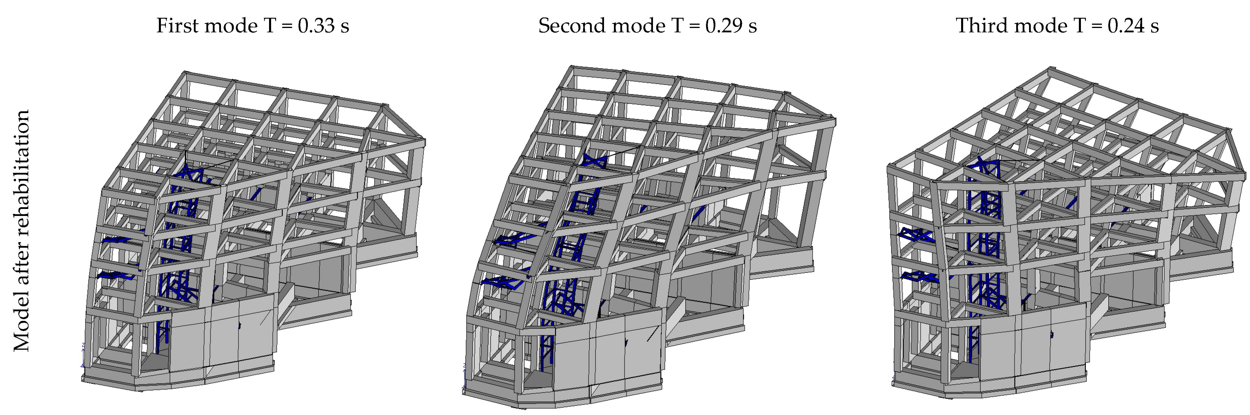
A reliable analysis of the structure after rehabilitation with extensive retrofitting should be carried out not only in terms of element strengthening but also in terms of global modification of masses and stiffnesses in the new configuration.
(5)
Dynamic linear analysis is, in many cases, not sufficient for the determination of deficits for structural assessment and subsequent retrofitting, while nonlinear static analysis facilitates the evaluation of the collapse mechanisms to know the most critical elements, in addition to an overall assessment in terms of displacement and base shear. Therefore, it is advisable to carry out pushover analyses both in the original condition and after the intervention to compare the two structural behaviors.
The strategy presented here for seismic adaptation is easily extensible to complex cases of highly irregular structures with changes in post-operam characteristics and with high degradation states.

Funding

This research received no external funding. The on-site works were funded by the Municipality of Lascari, Sicily, Italy.

Data Availability Statement

Data are available from the author on reasonable request.

Acknowledgments

Authors wish to acknowledge the team of ICARO PROGETTI (Palermo, Italy), particularly Arch. Benedetta Fontana and Eng. Giovanni Culotta, the Major and the Administration of Lascari Municipality, the Technical Management Office headed by Eng. Pietro Conoscenti, the inspector Arch. Elisa Costanzo and the construction company Juryleppe srl (manager: Antonio De Francisci, on-site supervisors: Leonardo and Daniela Morelli).

Conflicts of Interest

The author declares no conflicts of interest.

References

  1. Italian Ministry of Infrastructures. Norme Tecniche per le Costruzioni DM 14.01.2008; Consiglio Superiore LL. PP, Ed.; Italian Ministry of Infrastructures: Roma, Italy, 2008. (In Italian) [Google Scholar]
  2. Italian Ministry of Infrastructures. Norme Tecniche per le Costruzioni DM 17.01.2018; Consiglio Superiore LL. PP, Ed.; Italian Ministry of Infrastructures: Roma, Italy, 2018. (In Italian) [Google Scholar]
  3. Bru, D.; Gonzàlez, F.; Baeza, J.; Ivorra, S. Seismic behaviour of 1960’s RC buildings exposed to marine environment. Eng. Fail. Anal. 2018, 90, 324–340. [Google Scholar] [CrossRef]
  4. Saetta, A.; Simioni, P.; Berto, L.; Vitaliani, R. Seismic response of corroded r.c. structures. In Tailor Made Concrete Structures; Walraven, Stoelhorst, Eds.; Taylor & Francis: Abingdon, UK, 2008; pp. 1031–1035. [Google Scholar]
  5. Berto, L.; Vitaliani, R.; Saetta, A.; Simioni, P. Seismic assessment of existing RC structures affected by degradation phenomena. Struct. Saf. 2009, 31, 284–297. [Google Scholar] [CrossRef]
  6. Coccia, S.; Imperatore, S.; Rinaldi, Z. Influence of corrosion on the bond strength of the steel rebars in concrete. Mater. Struct. 2016, 49, 537–551. [Google Scholar] [CrossRef]
  7. Bossio, A.; Lignola, G.P.; Prota, A. An overview of assessment and retrofit of corroded reinforced concrete structures. Procedia Struct. Integr. 2018, 11, 394–401. [Google Scholar] [CrossRef]
  8. Minafò, G.; Di Trapani, F.; Amato, G. Strength and ductility of RC jacketed columns: A simplified analytical method. Eng. Struct. 2016, 122, 184–195. [Google Scholar] [CrossRef]
  9. Karayannis Chris, G.; Chalioris Constantin, E.; Sirkelis George, M. Local retrofit of exterior RC beam-column joints using thin RC jackets-An experimental study. Earthq. Engng Struct. Dyn. 2008, 37, 727–746. [Google Scholar] [CrossRef]
  10. Campione, G.; Cavaleri, L.; Di Trapani, F.; Ferrotto, M.F. Frictional Effects in Structural Behavior of No-End-Connected Steel-Jacketed RC Columns: Experimental Results and New Approaches to Model Numerical and Analytical Response. J. Struct. Eng. ASCE 2017, 143, 04017070. [Google Scholar] [CrossRef]
  11. Ferrotto, M.F.; Cavaleri, L.; Papia, M. Compressive response of substandard steel-jacketed RC columns strengthened under sustained service loads: From the local to the global behavior. Constr. Build. Mater. 2018, 179, 500–511. [Google Scholar] [CrossRef]
  12. Taleb, O.Y.; Susanne, H.; Ola, D.; Ghazi, A.-F.; Yahia, A.-J. Retrofitting of reinforced concrete beams using composite laminates. Constr. Build. Mater. 2011, 25, 591–597. [Google Scholar]
  13. Italian Ministry of Infrastructures. Linee Guida per la Progettazione, l’Esecuzione ed il Collaudo di Interventi di Rinforzo di Strutture di c.a., c.a.p. e Murarie Mediante FRP; Consiglio Superiore LL. PP, Ed.; Italian Ministry of Infrastructures: Roma, Italy, 2009. (In Italian) [Google Scholar]
  14. Ruggieri, S.; Vukobratović, V. The influence of torsion on acceleration demands in low-rise RC buildings. Bull. Earthq. Eng. 2024, 22, 2433–2468. [Google Scholar] [CrossRef]
  15. Kaatsız, K.; Sucuoğlu, H. Identification of torsionally stiff and flexible asymmetric systems, and their comparative seismic response evaluation for low-rise frames. J. Earthq. Eng. 2023, 28, 998–1014. [Google Scholar] [CrossRef]
  16. Landge, M.V.; Ingle, R.K. Comparative study of floor response spectra for regular and irregular buildings subjected to earthquake. Asian J. Civ. Eng. 2021, 22, 49–58. [Google Scholar] [CrossRef]
  17. Ruggieri, S.; Uva, G. Accounting for the spatial variability of seismic motion in the pushover analysis of regular and irregular RC buildings in the new Italian building code. Buildings 2020, 10, 177. [Google Scholar] [CrossRef]
  18. Rinaldi, Z.; Valente, C.; Pardi, L. A simplified methodology for the evaluation of the residual life of corroded elements. Struct. Infrastruct. Eng. 2008, 4, 139–152. [Google Scholar] [CrossRef]
  19. Al-Sulaimani, G.J.; Kaleemullah, M.; Basunbul, I.A.; Rasheeduzzafar. Influence of corrosion and cracking on bond behavior and strength of reinforced concrete members. ACI Struct. J. 1990, 87, 220–231. [Google Scholar]
  20. Robuschi, S.; Sumearll, J.; Fernandez, I.; Lundgren, K. Bond of naturally corroded, plain reinforcing bars in concrete. Struct. Infrastruct. Eng. 2021, 17, 792–808. [Google Scholar] [CrossRef]
  21. Zheng, L.; Liu, S. Anchorage of Plain, Naturally Corroded Reinforcement Bars with End-Hooks. Master’s Thesis, Department of Architecture and Civil Engineering, Chalmers University of Technology, Gothenburg, Sweden, 2021. [Google Scholar]
  22. Habib, A.; Yildirim, U.; Eren, O. Column repair and strengthening using RC jacketing: A brief state-of-the-art review. Innov. Infrastruct. Solut. 2020, 5, 75. [Google Scholar] [CrossRef]
  23. Campione, G.; Fossetti, M.; Giacchino, C.; Minafò, G. RC columns externally strengthened with RC jackets. Mater. Struct. 2014, 47, 1715–1728. [Google Scholar] [CrossRef]
  24. Dolce, M.; Manfredi, G. Linee Guida per Riparazione e Rafforzamento di Elementi Strutturali, Tamponature e Partizioni; Doppiavoce: Naples, Italy, 2011; ISBN 978-88-89972-29-8. (In Italian) [Google Scholar]
  25. Campione, G. RC Columns Strengthened with Steel Angles and Battens: Experimental Results and Design Procedure. Pract. Period. Struct. Des. Constr. ASCE 2013, 18, 1–11. [Google Scholar] [CrossRef]
  26. Eurocode 8, CEN; Design of Structures for Earthquake Resistance. Part 3: Strengthening and Repair of Buildings. European Committee for Standardization (CEN): Brussels, Belgium, 2003.
  27. Eurocode 4, CEN; Design of Composite Steel and Concrete Structures. Part 1-1: General Rules and Rules for Buildings. European Committee for Standardization (CEN): Brussels, Belgium, 1994.
  28. Adam, J.M.; Ivorra, S.; Pallares, F.J.; Giménez, E.; Calderón, P.A. Axially loaded RC columns strengthened by steel cages. Proc. Inst. Civ. Eng. ICE Struct. Build. 2009, 162, 199–208. [Google Scholar] [CrossRef]
  29. Adam, J.M.; Giménez, E.; Calderón, P.A.; Pallares, F.J.; Ivorra, S. Experimental study of beam-column joints in axially loaded RC columns strengthened by steel angles and strips. Steel Compos. Struct. 2008, 8, 329–342. [Google Scholar] [CrossRef]
  30. Nagaprasad, P.; Sahoo, D.R.; Rai, D.C. Seismic strengthening of RC columns using external steel cage. Earthq. Engng Struct. Dyn. 2009, 38, 1563–1586. [Google Scholar] [CrossRef]
  31. Garzón-Roca, J.; Ruiz-Pinilla, J.; Adam, J.M.; Calderón, P.A. An experimental study on steel-caged RC columns subjected to axial force and bending momento. Eng. Struct. 2011, 33, 580–590. [Google Scholar] [CrossRef]
  32. Li, J.; Gong, J.; Wang, L. Seismic behavior of corrosion-damaged reinforced concrete columns strengthened using combined carbon fiber-reinforced polymer and steel jacket. Constr. Build. Mater. 2009, 23, 2653–2663. [Google Scholar] [CrossRef]
  33. Colajanni, P.; Recupero, A.; Spinella, N. Increasing the flexural capacity of RC beams using steel angles and pre-tensioned stainless steel ribbons. Struct. Concr. 2016, 17, 848–857. [Google Scholar] [CrossRef]
  34. Cirtek, L. RC columns strengthened with bandage—Experimental programme and design recommendations. Constr. Build. Mater. 2001, 15, 341–349. [Google Scholar] [CrossRef]
  35. Granata, M.F.; Recupero, A. Serviceability and Ultimate Safety Checks of Segmental Concrete Bridges through N-M and M-V Interaction Domains. J. Bridge Eng. ASCE 2015, 20, B4014003. [Google Scholar] [CrossRef]
Figure 1. Plans and elevations of the original structure. (a) Intermediate level with the mesh of beams of the framed structure; (b) Plan of the square at the top; (c) Elevation (with the foundation on three different levels along the slope); (d) Section of the building.
Buildings 14 01064 g001
Figure 2. Pictures of the original situation. (a) Overview of the building and of the structural frame. (b,c) State of degradation in elements with concrete spalling and reinforcement corrosion.
Buildings 14 01064 g002
Figure 4. Spectra of the horizontal component. (a) Elastic spectra for each limit state. (b) Elastic and design spectra for the Ultimate Limit State SLV for different values of parameter q.
Buildings 14 01064 g004
Figure 5. Modal shapes for the first three modes in the original condition.
Buildings 14 01064 g005
Figure 6. Comparison between uncorroded and corroded elements. (a) Uncorroded structure. N-M deficiencies on columns. (b) Uncorroded structure. V deficiencies for stirrups. (c) Corroded structure. N-M deficiencies on columns. (d) Corroded structure. V deficiencies for stirrups.
Buildings 14 01064 g006
Figure 7. Results of pushover analysis on the building in its original conditions. (a) Force-displacement curve for the worst combination of loads. (b) Plastic hinges (blue open hinges, red broken hinges).
Buildings 14 01064 g007
Figure 8. Concrete jacketing of degraded columns. (a) Damaged column with broken stirrups; (b) Reinforcement reorganization and integration; (c,d) Mortar casting and cross-section restored.
Buildings 14 01064 g008
Figure 9. Views of retrofit interventions with steel jacketing and exoskeleton. (a) Shoring of beams during assembling of angles and battens; (b) Retrofitted columns; (c) Completion of columns retrofitting and new steel floor assembling; (d) Preparing in situ casting of floor slab.
Buildings 14 01064 g009
Figure 10. Drawings of retrofit interventions. (a) Plan of a new floor. (b) Connection between columns and beams together with CFRP wrapping. (c) Steel jackets of columns.
Buildings 14 01064 g010
Figure 11. CFRP wrapping and plating within the overall retrofit intervention. (a,b) Views of CFRP plates and fabrics beneath beams; (c) pull-out tests.
Buildings 14 01064 g011
Figure 12. Model of cross-section adopted for the calculation of ULS to bending with FRP plating.
Buildings 14 01064 g012
Figure 13. Results of the (N,M) checks in beams and columns after rehabilitation, in terms of the exploitation rate (values under 1 satisfy this check).
Buildings 14 01064 g013
Figure 14. Modal shapes for the first three modes after rehabilitation.
Buildings 14 01064 g014
Figure 15. Results of pushover analysis on the building after rehabilitation. (a) Force-displacement curve for the worst combination of loads. (b) Plastic hinges (blue open hinges, red broken hinges).
Buildings 14 01064 g015
Table 1. Global structural parameters for Italian Standards.
Class Life Vn
[Years]
Functional
Coefficient
Period Vr
[Years]
Type of GroundSlope
IV1002.0200.0BT2
Table 2. Parameters of spectra adopted for the dynamic analysis.
Limit StateProb. of Exceeding [%]Tr
[Years]
ag
[g]
Fo
[-]
T*c
[s]
S
[-]
TB
[s]
TC
[s]
TD
[s]
SLO81.01200.1012.3200.2801.4400.1320.3972.005
SLD63.02010.1282.3200.2901.4400.1360.4092.110
SLV10.018980.2872.4800.3201.3380.1470.4422.748
SLC5.024750.3132.5100.3201.3030.1470.4422.851
Disclaimer/Publisher’s Note: The statements, opinions and data contained in all publications are solely those of the individual author(s) and contributor(s) and not of MDPI and/or the editor(s). MDPI and/or the editor(s) disclaim responsibility for any injury to people or property resulting from any ideas, methods, instructions or products referred to in the content.

