Article

Rotational Stiffening Performance of Roof Folded Plates in Torsion Tests and the Stiffening Effect of Roof Folded Plates on the Lateral Buckling of H Beams in Steel Structures

1
National Institute of Technology, Sendai College, Sendai 981-1239, Japan
2
Graduate School of Engineering, Tohoku University, Sendai 980-8577, Japan
*
Author to whom correspondence should be addressed.
Buildings 2024, 14(4), 1158; https://doi.org/10.3390/buildings14041158
Submission received: 14 March 2024 / Revised: 11 April 2024 / Accepted: 14 April 2024 / Published: 19 April 2024

Abstract

:
Non-structural members, such as roofs and ceilings, become affixed to main beams that are known as structural members. When such main beams experience bending or compressive forces that lead to lateral buckling, non-structural members may act to restrain the resulting lateral buckling deformation. Nevertheless, neither Japanese nor European guidelines advocate for the utilization of non-structural members as lateral buckling stiffeners for beams. Additionally, local buckling ensues near the bolt apertures in the beam–roof folded plate connection due to the torsional deformation induced by the lateral buckling of the H beam, thereby reducing the rotational stiffness of the roof folded plate to a percentage of its ideal stiffness. This paper conducts torsional experiments on roof folded plates, and with various connection methods between these plates and the beams, to comprehend the deformation mechanism of roof folded plates and the relationship between their rotational stiffness and the torsional moment. Then, the relationship between the demand values against restraining the lateral buckling of the main beam and the experimentally determined bearing capacity of the roof folded plate is elucidated. Results indicate the efficacy of utilizing the roof folded plate as a continuous brace. The lateral buckling design capacity of H beams that are continuously stiffened by roof folded plates is elucidated via application of a connection method that ensures joint stiffness between the roof folded plate and the beam while using Japanese and European design codes.

1. Introduction

The collapse or detachment of non-structural members, such as roofs and ceilings, within school gymnasiums during seismic occurrences [1,2] or typhoons [3,4] poses impediments to their utilization as evacuation shelters [1,2,3,4]. The collapse or detachment of non-structural members is instigated by the imposition of bending moments or compressive forces upon main beams, which are structural members, amidst seismic forces or typhoons. These forces may incite lateral buckling within the beams. In their investigation of the lateral buckling of beams, Timoshenko and Bleich derived elastic lateral buckling load equations [5,6] based on elastic theory and analyzed them using elastic eigenvalue analysis. Notably, Nethercott studied ideal boundary conditions [7] for beam ends in moment resisting frames, while Suzuki et al. examined the effect of web deformation on the lateral buckling of beams [8]. Previous research [9,10,11,12,13,14] has demonstrated the influence of moment distribution on a range of bending moments, from uniform bending to inversely symmetric, on the lateral buckling load of beams. Research into the effect of stiffeners [15] on the restraining of lateral buckling deformations in beams has focused on stiffeners positioned at the center span [16,17,18,19] as well as discrete stiffeners, like small beams, and has been undertaken through numerical analyses [20,21,22,23,24,25,26] and experimental studies [27,28,29,30]. These investigations into discrete stiffening have yielded elastic lateral buckling load equations, illuminating the effects of stiffening spacing [21,22], encompassing equally spaced or end-only stiffening [18], and the precise positioning of stiffeners [23] within the beam section. Furthermore, these inquiries have elucidated the lateral buckling capacity [25] and post-buckling deformation behavior [26] of beams under varied loading conditions, with parameters including the rigidity [24] of the stiffeners. Additionally, experimental studies have delved into the spacing of stiffeners [28] and the deformation performance [29] of beams subjected to lateral buckling under diverse loading conditions [27], exploring the effect of beam end restraints [30] by columns on lateral buckling. One member that is continuously affixed to a beam in an actual structure is a floor slab. The lateral buckling of beams, with floor slabs serving as composite members of steel and concrete, has been examined [31,32,33,34,35]. Here, the floor slab is replaced by a continuous spring, facilitating the numerical analysis of the effects of horizontal deformation of the compression flange [36] and the bending and torsional deformation of the beam [37] on the lateral buckling load.
When the main beam in an actual structure experiences lateral buckling, stress is transferred to non-structural members attached to the beams. In essence, the nonstructural members resist the stress transmitted from the main beams, thereby contributing to the restraint of lateral buckling deformation [38,39,40,41,42,43]. However, neither Japanese design codes [44,45,46] nor the European Eurocode [47] advocate for the utilization of non-structural members as lateral buckling stiffeners for beams, and neither do they specify the requisite stiffener values.
Non-structural elements, like the roof folded plates [48,49] (referred to as profile sheets in the Eurocode [47]) depicted in Figure 1 and Figure 2, are affixed to the upper flange of the beam and are installed continuously along its length. During lateral buckling deformation of the beam in particular, and as illustrated in Figure 3a, stresses (horizontal forces: F or rotational moments: M) occur at the junction between the beam and the roof folded plate. At this junction, horizontal and rotational deformations of the beam are constrained. However, the stiffness of the roof folded plate, which restrain the horizontal and rotational deformations of the beam, is lower than the stiffness of the buckling reinforcement, such as that provided by a small beam affixed to the beam. Furthermore, concrete slabs exhibit restraining properties in both the in-plane and out-of-plane directions of the beam [50], while roof folded plates exert minimal in-plane forces on the beam and provide continuous stiffening in the out-of-plane direction of the beam.
Kimura et al. have employed numerical analysis to postulate that a beam and a roof folded plate should be rigidly interconnected, subsequently reconfiguring the roof folded plate with evenly distributed horizontal and rotational springs, as depicted in Figure 3b, in order to scrutinize the effects of the loading conditions [38,39,40] and the beam edge restraint [41,42,43] imposed by the column on the lateral buckling of the H beam with the roof folded plate. The horizontal and rotational spring stiffnesses, denoted as ku and kθ in Figure 3b, respectively, denote the elastic stiffness of the roof folded plate.
Yoshino et al. [51] delved into the stiffening effect of a roof folded plate on the reverse buckling of a beam through partial frame loading tests. In the depicted actual structure in Figure 2a, tight frames are meticulously welded to the H beams in a linear configuration along the beam length at the center of the top flange and are fastened to each top flange of the roof folded plate. As per the findings from the partial frame loading tests [51], the out-of-plane torsional deformation resulting from the lateral buckling of the H beams induced localized buckling near the bolt holes in the beam–roof folded plate junctions. Consequently, the rotational stiffness of the roof folded plate diminished to a fractional percentage of its theoretical stiffness due to this localized buckling. the rotational stiffness of the roof folded plate could be enhanced by refining the connector or connection method between the beam and the roof folded plate.
In the exploration of roof folded plates, the shear stiffness and shear seating behavior of folded plates under various edge support conditions have been elucidated through numerical analysis [52,53] and experiments [54]. Furthermore, experiments assessing the compression and shear strength [55,56] of thin steel folded plates as wall members have been conducted, while investigations into buckling tests [57,58,59] and numerical analyses [60,61] have centered on corrugated steel plate web beams.
Studies focusing on the bending performance of roof folded plates as roof members have unveiled their bending strength, considering variants with and without holes for equipment [62,63,64,65] and their reference manuals [48,49,66,67,68].
Moreover, studies leveraging the joints between roof members and beams as variables have revealed shear tests of roof folded plates when these joints are welded [69,70], as well as the bearing capacity of the joints of thin steel folded plates under distributed loads, such as wind loads [71].
These studies have exposed the holding performance of roof folded plates [52,53,54,55,56,57,58,59,60,61,62,63,64,65,66,67,68] and the mechanical behavior of roof folded plate–beam joints [69,70,71] within actual structures. However, they did not endeavor to employ the roof folded plate, a non-structural member, as a lateral buckling stiffener for beams. Furthermore, the mechanism of stress transfer from the beam to the folded plate due to variations in joint geometry remains undisclosed.
This paper conducts torsional experiments on roof folded plates, with various connection methods between them, in order to comprehend the deformation mechanism of roof folded plates and the relationship between their torsional moment and rotational stiffness. Next, the structures of roof members, assumed as continuous braces, and structural elements, such as large and small beams, will be investigated. Then, the relationship between the demand values against restraining the lateral buckling of the large beam and the experimentally determined bearing capacity of the roof folded plate will be elucidated. This aims to verify the feasibility of utilizing the roof folded plate as a continuous brace.
Additionally, Yoshino et al. [38,39,40,41,51] have investigated the design capacity associated with the use of the Japanese design code [46]. In this paper, the lateral buckling design capacity of H beams continuously stiffened by roof folded plates is elucidated by applying a connection method that ensures the joint stiffness between the roof folded plate and the beam using Japanese and European design codes [46,47].

2. Outline of Torsional Experiment on Roof Folded Plates

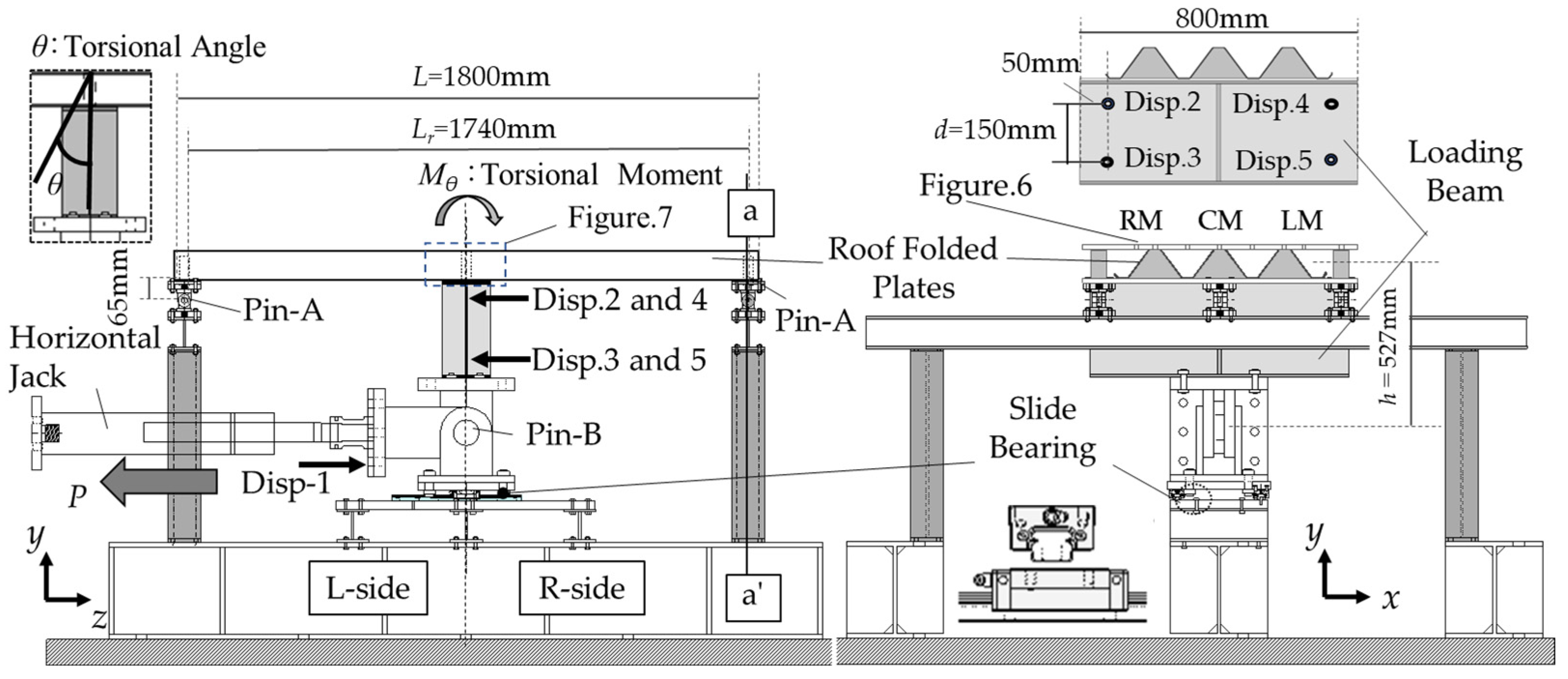
2.1. Outline of Torsional Experiment Apparatus

Figure 4 illustrates the experimental setup for conducting a torsion test on a roof folded plate. The specimen depicted in Figure 5 exemplifies a roof folded plate utilized in practical applications. With the objective of this paper being to determine the rotational stiffness of the connection between the roof folded plate and the beam, a cross-sectional profile [48,49], conducive to bolting onto a tight frame, as portrayed in Figure 2(b-1), and commonly encountered in actual structures in Japan, is employed. The length of the roof folded plates is L = 1800 mm. The width of the cross-section is 600 mm, equivalent to the combined width of three layers of a single roof folded plate. The boundary condition at the edge of the specimen in the z-direction is a pin on both the left and right sides (pin A, as shown in Figure 4). The loading beam possesses an H-shaped cross-section, H-300 × 150 × 6.5 × 9. The left side or the right side is identified as either the L side or R side from the center of pin B, which corresponds with the position of the loading beam web. Pin B, as delineated in Figure 4, is situated at the base of the loading beam. Pin B can pivot in two directions: vertically and horizontally. The pin plate of pin B is linked to the bottom flange of the loading beam and to the jack and slide bearing. Pin B is located atop the slide bearing, thus assuming the role of a pin roller support. The extremities of the test specimen in Figure 6, a roof folded plate, are vertically clamped between two plates, top and bottom, as exemplified at the a–a′ line of Figure 4. This is enacted to forestall local buckling at the peripheries of the roof folded plate. The roof folded plate is fastened 30 mm from the edge. The distance between the pins at both ends is Lr = L − 2 × 30 mm = 1740 mm.

2.2. Loading Protocols

The jack draws the loading beam in the z-axis direction, displacing pin B horizontally and inducing rotation. The specimen undergoes a torsional moment due to the rotation of the loading beam. The loading is monotonous.

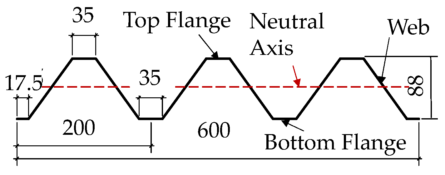
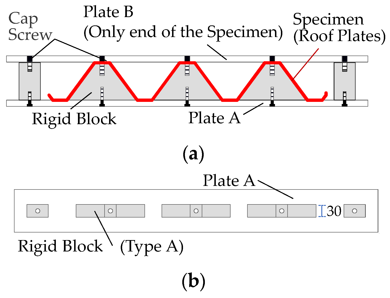
2.3. Specimen Configuration

Figure 7 illustrates the method of connection for the joint between the loading beam and the specimen. The H beam and the roof folded plate are connected via the plate (PL-800 × 150 × 15) and connector depicted in Figure 7. Bolts are used to join the plates and loading beam. Typically, a tight frame acts as a connector between beams and folded plates, as observed in actual structures. Connectors are bolted to the top flange of the folded plate.
The connector depicted in Figure 7a is a tight frame (2.3 mm thick) welded to the plate. The connection method TF11 illustrated in Figure 7(a-1) resembles the actual structure depicted in Figure 2a, where the tight frame is linearly welded in a single row along the beam’s length at the midpoint of the top flange. However, the connectors in TF11 may concentrate stress only at the bolted joints during torsional deformation of the beam. Therefore, TF21 in Figure 7(a-2) is a connector in which the tight frame is welded in two rows along the length of the beam on the top flange, increasing the number of bolted joint locations. Here, previous experiments [51] have confirmed the deformation of the tight frame. Additionally, the shape of the roof folded plate differs from that of the tight frame; the height of the roof folded plate shown in Figure 5 is 88 mm, while the height of the tight frame is 93 mm. Consequently, even when the roof folded plate and tight frame are bolted together, a 5 mm gap exists between the bottom flange of the roof folded plate and the tight frame. Furthermore, the roof folded plate is positioned 7.3 mm higher than the top flange of the loading beam.
This paper also introduces connectors that are designed to enhance the contact surface between the roof folded plate and the connector, when compared with TF11, and to increase rotational stiffness. The connector depicted in Figure 7b is a rigid block machined to match the cross-section and the height of the roof folded plate. When the roof folded plate and the connector are joined, the bottom flange of the roof folded plate contacts the plate. Type A employs rigid steel blocks 30 mm wide, while type B uses blocks 60 mm wide. Rigid blocks offer greater stiffness compared with tight frames. Roof folded plates are affixed to rigid blocks using high tension bolts. Connectors RA11 and RB12, shown in Figure 7(b-1,b-2), are positioned at the center of the top flange of the loading beam. Connector RA21, depicted in Figure 7(b-3), is positioned in two rows on the top flange of the loading beam. Furthermore, with the goal of achieving a closer approximation of rigid contact when compared with connector RA21 and to elucidate the effect of the presence or absence of a joint on the bottom flange of the roof folded plate, connector RA22, shown in Figure 7(b-4), joins the lower flange in addition to the joints of connector RA21.
Table 1 presents the list of specimens. Ten specimens were evaluated in the experiment for the following three variables: (1) plate thickness (t = 0.8, 1.0 mm), (2) connector (tight frame, rigid block-type A, B), and (3) bolt joint positions (top flange, top and bottom flanges).

2.4. Material Properties

The material of the roof folded plate is galvanized steel sheet [72], selected for its corrosion resistance which makes it suitable for roofing applications. The material test results for the roof folded plate are presented in Table 2. The tensile strength test of steel members was conducted according to JIS Z 2241 [73]. The yield and ultimate strength of the roof folded plate are, respectively, 309 to 322 N/mm² and 380 to 483 N/mm².

2.5. Measurement Methods

Figure 8 elucidates the locations for strain measurement. Strain gauges are affixed to both facets of the roof folded plate to quantify plate bending, as depicted in Figure 8b.

3. Results of Torsional Experiment on Roof Folded Plate

3.1. Rotational Stiffness and Torsional Moment of Roof Folded Plate

This section delineates the load–displacement correlation for each specimen to elucidate the impacts of the experimental parameters.
Figure 9 illustrates the correlation between torsional moment Mθ,i and rotation angle for the torsion experiment. The vertical axis depicts the ratio of the torsional moment experienced by the roof folded plate during the experiment to the yield bending moment of the roof folded plate My,r. Mθ,i and My,r can be calculated using the following equation.
M θ , i = P · h
M y , r = σ y , r · Z r
where h signifies the distance between the pin and the roof folded plate, h = 527 mm (refer to Figure 4); σy,r represents the yield stress of the roof folded plate in Table 2; and Zr denotes the section modulus. The horizontal axis represents the ratio of the rotation angle θ of the loading beam to the rotation angle θy,r at yield bending moment My,r. The rotation angle θ of the loading beam is calculated as the average of the difference in horizontal displacements u measured at two points (“disp.3–disp.2” and “disp.5–Disp.4”) on either side of the beam, as shown in Figure 4, divided by the distance d between measurements. This is obtained from the following equation:
θ = u d i s p . 3 u d i s p . 2 / d + u d i s p . 5 u d i s p . 4 / d / 2
This experiment considered a situation in which beams linked to roof folded plates laterally buckled as illustrated in Figure 9c The rotational stiffness kθ,i of the roof folded plate is defined as the ratio of the torsional moment Mθ,i to the torsional deformation θ occurring in the roof folded plate. kθ,i corresponds with the slope of the Mθ,iθ relationship in Figure 9a,b,d,e. The symbol “i” in kθ,i represents the three rotational stiffness values (i = 0, 1, 2), and is derived from the equation below.
k θ , i = M θ , i θ
The solid line in Figure 9 represents the tangent line of the measured data. The inclination of the tangent line is defined as the initial rotational stiffness kθ,1. The ▷ horizontal triangle plot indicates the juncture at which the slope is more than 5% lower than the tangent slope. The vertical triangle plot signifies the point of maximum moment. The dashed line delineates the slope connecting the origin and the plot. The slope of the dashed line is defined as the secant rotational stiffness kθ,2. The theoretical rotational stiffness kθ,0 can be calculated from Equation (5).
k θ , 0 = 12 E r I r L r
where ErIr represents the bending stiffness of the roof folded plate.
Figure 9a illustrates the experimental results for specimens with varying plate thicknesses. In the TF11 specimen, where a single row of tight frames is welded along the length of the beam at the center of the top flange, the difference in rotational stiffness, indicated by the slope of the tangent line, shows minimal variation with plate thickness. This is attributed to the small stiffness of the roof folded plate–beam joint, making it difficult to transmit torsional moments through the joint effectively. Conversely, in the TF21 specimen with two rows of tight frames welded to the top flange of the loading beam, torsional moments are induced in the roof folded plate via the two bolted joints, thereby demonstrating the bending stiffnesses of the roof folded plates at each plate thickness according to the stiffness of the roof folded plate–beam joint. Consequently, there exists a difference in rotational stiffness among different plate thicknesses. Specifically, the increase in rotational stiffness of the specimen with t = 1.0 relative to t = 0.8 is 1.2 times greater than that of the specimen with t = 0.8.
However, the theoretical rotational stiffness due to plate thickness, as indicated in Equation (5), is expected to increase by about 1.5 times. This discrepancy arises because the joints assumed for the theoretical rotational stiffness are rigid, whereas the joints between the roof folded plate and the beam in the experiment are not rigid. Hence, an increase in the rate of rotational stiffness in the experiment is deemed to be smaller than the equivalent theoretical value.
Similarly, while the yield moment calculated from Equation (3) escalates by a factor of 1.4 with plate thickness, the rate of maximum load increase with plate thickness for the TF21 specimen is 1.2. This discrepancy is attributed to localized fracture at the bolted joints of the TF21 specimen, as depicted in Figure 10, which is discussed subsequently.
Figure 9b illustrates the experimental results for specimens with various types of connectors. In the TF11 specimen, Mθ,i starts to increase after θ/θy,r = 15, when the bottom flange of a roof folded plate makes contact with the H beam serving as the reaction force beam. As depicted in Figure 7(a-1) for the TF11 specimen, there exists a 7.3 mm gap between the folded plate and the upper flange of the beam. Consequently, the roof folded plate remains unaffected by the torsional deformation of the beam until the lower flange of the roof folded plate contacts the upper flange of the beam. Upon contact, torsional moment is generated in the roof folded plate through two points: the contact surface between the top flange of the beam and the bottom flange of the roof folded plate, and the bolted joint. Consequently, for the RA11 specimen, which is a rigid block with no gap between the connector and the roof folded plate, the torsional moment starts to increase from the initial load. Conversely, for the TF21 specimen with two rows of tight frames welded to the top flange of the loading beam, the torsional moment begins to increase from the beginning of loading. The initial rotational stiffness of TF21, denoted as kθ,1, exhibits approximately 2 to 3% of the theoretical stiffness kθ,0. This is attributed to bending stresses in the top flange of the roof folded plate from the initial load (θ/θy,r = 0) through the two bolted joints between the roof folded plate and the tight frame. The initial rotational stiffness of RA11, denoted as kθ,1, exceeds the rotational stiffness of TF21. This is due to the greater stiffness of the roof folded plate–beam connection in RA11 compared with TF21.
Figure 9d displays the results for different numbers of bolts on the top flange of the beam–roof folded plate joints. Mθ,1 is defined as the initial torsional moment, indicating the torsional moment at the point of the ▷ plot. The torsional moment of the roof folded plate in RB12 increases from that of RA11, but the initial rotational stiffness kθ,1 is approximately 4.1% of the theoretical stiffness kθ,0 and remains nearly the same for both specimens. On the other hand, the torsional moment and initial rotational stiffness of RA22 are lower than those of RA11, despite the higher theoretical stiffness assumed for rigid connections between the roof folded plate and the beam in RA21 compared with RA11. This is attributed to the fact that the specimen in RA21 experienced plate bending deformation in the mountain flange of the thin roof folded plate from the beginning of loading, as discussed later in Figure 10 and Figure 11.
Figure 9e illustrates the comparison between the connector and the lower flange of the roof folded plate when jointed and unjointed. The initial rotational stiffness kθ,1 of RA22 with the upper and lower flanges joined is approximately 12% of kθ,0. The initial rotational stiffness of RA22 is about three times that of RA21. Despite the increased number of joint points from RA21 and the increased rotational stiffness, the local deformation at the joints of the thin roof folded plates and the bending deformation of the roof folded plates at the contact surface of the connectors reduce the rotational rigidity of the roof folded plates. This results in the experimental rotational stiffness becoming only about 12% of the theoretical stiffness assumed for rigid connections between the roof folded plate and the beam.

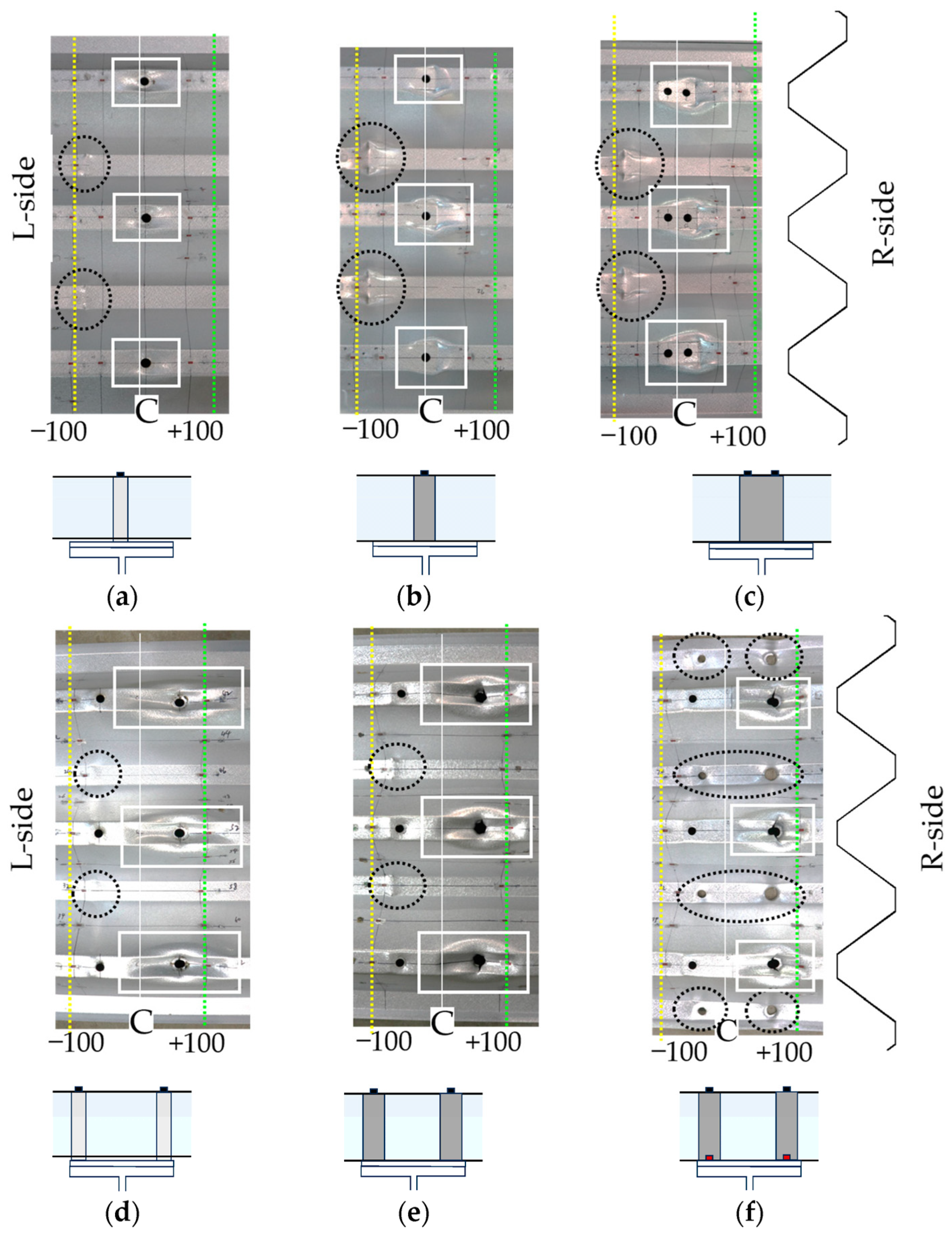
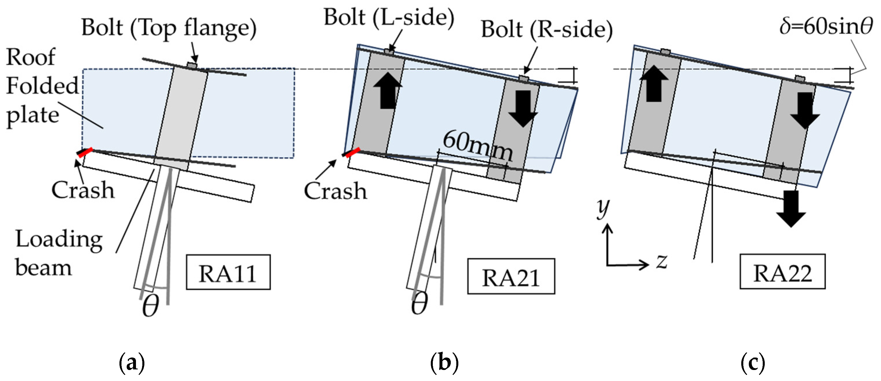
3.2. Deformation Mechanism of Roof folded Plate

Figure 10 illustrates the deformation of the roof folded plate post-experiment. In specimens TF11, RA11, and RB12, connectors are welded at the midpoint of the top flange, leading to plate local deformation near the bolted joint indicated by the white box. Additionally, bending deformation is observed at the joint where the bottom flange meets the top flange of the loading beam, marked by the black circle. Notably, the bending deformation in RA11 surpasses that of TF11, likely due to the absence of clearance between the roof folded plate and the connector.
In specimens with two rows of connectors welded to the top flange, highlighted by white boxes (TF21 and RA21), significant local deformation, terminal loss, and rupture were observed at the bolted joint of the top flange on the R side. Particularly in RA22, where the bottom flange of the roof folded plate was also bolted together, the bottom flange encircled in black exhibited a wider hole at the joint on the R side than on the L side, resulting in damage. This discrepancy arises because the bolted joint of the lower flange on the L side is pushed up against the plate in a plane, while only the bolt is pulled downward on the R side.

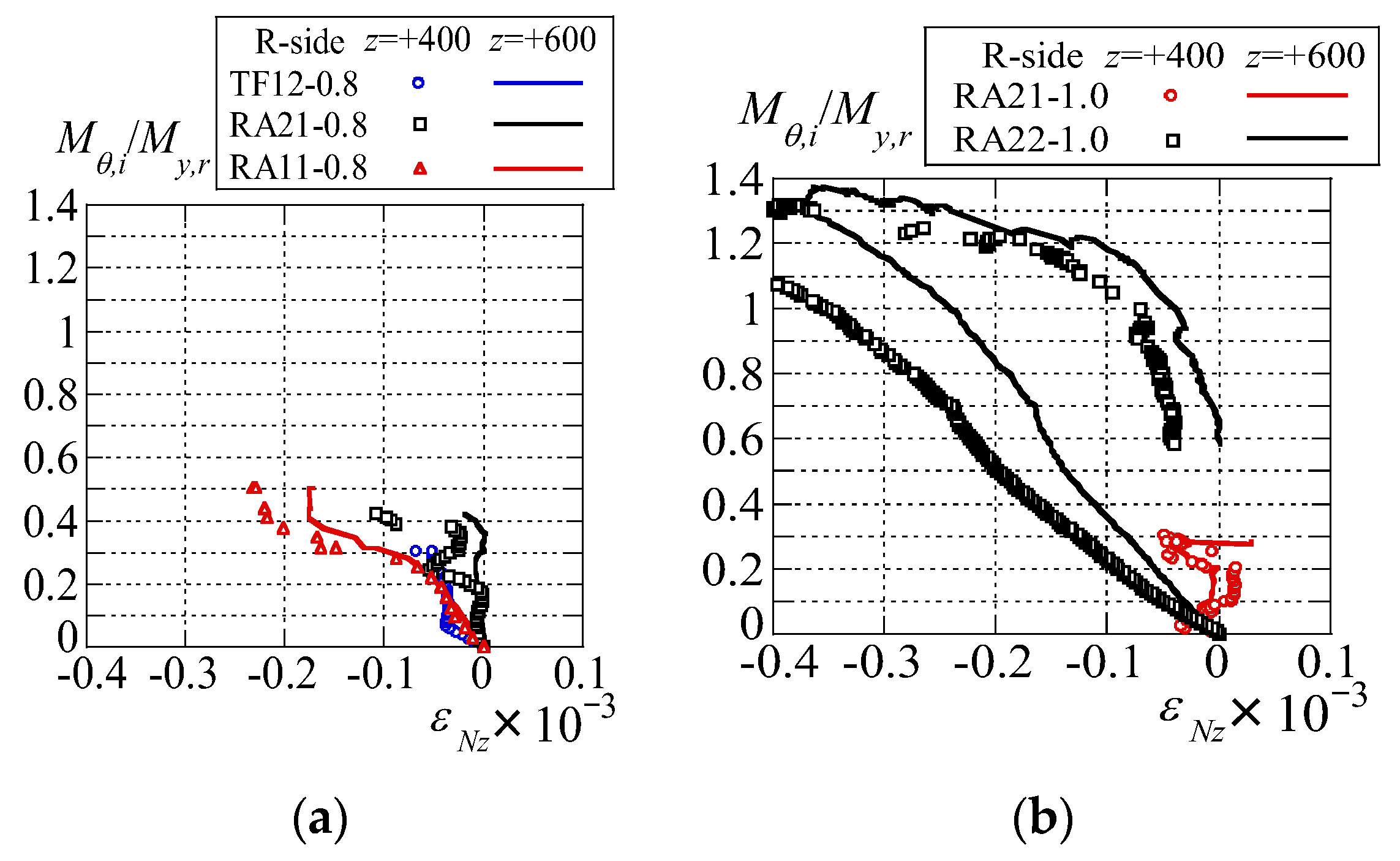
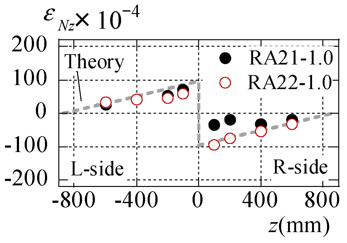
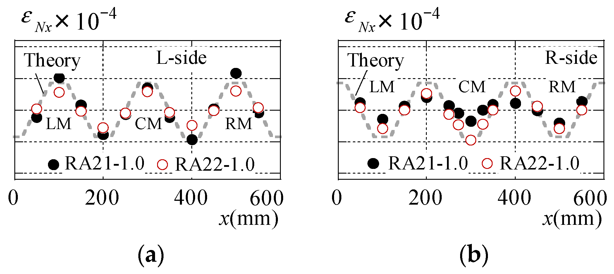
3.3. Stress State of Roof Folded Plate

Figure 11 illustrates the correlation between the plate bending strain εM at the top flange of the roof folded plate and the torsional moment at the beam−roof folded plate connection. The strain is calculated according to the subsequent equation.
ε M = ε f ε b / 2
where εf signifies the strain on the surface of the measurement point and εb denotes the strain on the back surface of the measurement point. The strain is measured at the top flange of the roof folded plate, indicated by “CM” in Figure 8 at z = ±100 mm.
In Figure 11a,b, the plate bending strain of TF21 and RA21 emerges from the initial loading. The plate bending strain on the right side (z = +100 mm, solid line) surpasses that on the left side (z = −100 mm, dashed line). When the loading beam undergoes torsion, the connectors affixed to the beam rotate, as illustrated in Figure 12b. As the connector rotates, the bolted joint on the right side connecting the connector and the roof folded plate is subjected to downward pulling along the y-axis, as indicated by the downward arrow in Figure 12b, and offers resistance. Consequently, plate bending deformation concentrates on the bolted joint on the right side earlier than on the left side, resulting in higher plate bending stresses. Therefore, the initial rotational stiffness of RA21 is presumed to be lower than that of RA11 in Figure 9b.
Figure 13 illustrates the axial strain εNz of the central top flange (CM) on the R side of the roof folded plate. At z = +400 mm and z = +600 mm, the axial strain of RA22 (specimen with top and bottom flanges joined) surpasses that of other joining methods (specimen with only top flanges joined). When the bottom flange of the roof folded plate is attached to the beam, the bolted joint is subjected to downward pulling along the y-axis due to the torsion of the loading beam, as indicated by the lower arrow in Figure 12c. Consequently, bending stresses arise in both the top and bottom flanges of the roof folded plate, particularly on the right side of the roof folded plate. Therefore, the cross-section at the joint location is constrained, resulting in bending deformation along the length of the roof folded plate. The axial strain of RA22 rapidly decreases near the maximum proof stress. As depicted in Figure 9e, the RA22 specimen, where the bottom flange of the roof folded plate is joined at the bolted joint, exhibits a smaller rotation angle needed to reach the maximum torsional moment when compared with the RA21 specimen where only the top flange of the roof folded plate is joined. This difference leads to early end failure.
Figure 14 illustrates the axial strain εNz distribution of the central top flange CM in the z-axis direction at 0.1 My,r. The gray dotted line represents the theoretically elastic strain when the roof folded plate is held flat. The theoretical elastic strain εN0 is calculated using the subsequent equation.
ε N 0 = σ E r = M θ , i 2 E r Z r
where Zr denotes the section modulus of the roof folded plate, as delineated in the 600 mm wide segment illustrated in Figure 5.
The axial strain on the R side of RA21, where only the top flange of the roof folded plate is connected, is nearly zero. The axial strain of RA22, with the attachment of the top and bottom flanges of the roof folded plate, corresponds with the elastic theoretical strain stipulated in Equation (7). Upon affixing the bottom flange of the roof folded plate to the beam, the entire cross-sectional area of the joint undergoes deformation when subjected to torsion by the loading beam. Therefore, the torsional moment induced in the roof folded plate due to the beam’s torsion leads to the bending moment distribution depicted by the gray dashed line in Figure 14 and is transmitted along the length directions (L and R sides) of the roof folded plate.
Figure 15 delineates the distribution of axial strain εNx along the x-axis for a roof folded plate. The axial strain εNx is gauged at z = ±100 mm. The gray dotted line is deduced from Equation (7). The axial strain on the left side of the RA21 specimen conforms to the elastic theoretical strain expounded in Equation (7). The axial strain on the right side deviates considerably from the theoretical value across the entire cross-section. In the RA21 specimen, the torsional moment on the right (R) side of the roof folded plate is small. In the RA22 specimen, the axial strain on the left (L) and the right (R) sides are close to the elastic theoretical strain. The roof folded plates of the RA22 specimen exhibit a more uniform cross-sectional deformation when compared with those of the RA21 specimen.

3.4. Summary of Torsion Experiment Results

Table 3 exhibits the rotational stiffness ratio kθ,i/kθ,0 and torsional moment ratio Mθ,i/My,r of each specimen at the initiation of stiffness reduction and at maximum load. The torsional moment Mθ,1 corresponds to moment at the ▷ plot in Figure 9, while the maximum torsional moment Mθ,2 corresponds with the moment at the plot in Figure 9. The rotational stiffness ratio kθ,i/kθ,0 is calculated by dividing the initial rotational stiffness kθ,1 or the secant rotational stiffness kθ,2 by the theoretical rotational stiffness kθ,0 in Equation (5). The torsional moment ratio Mθ,i/My,r is calculated by dividing the torsional moment Mθ,1 at the initiation of stiffness reduction or at the maximum moment Mθ,2 by the yield moment My,r of the roof folded plate.
The initial rotational stiffness ratio kθ,1/kθ,0 and torsional moment ratio Mθ,1/My,r at the initiation of stiffness reduction increased from 2.85% to 12.4% and from 0.07 to 0.57, respectively, depending on the joining method. Theoretical rotational stiffness assumes that the roof folded plate and beam connections are rigidly connected, but the rotational stiffness of the joint in this experiment corresponds with the sum of the stiffness of the bolted joint and the bending stiffness of the roof folded plate.
The magnitude of the moment transmitted to the roof folded plate depends on the stiffness of the bolted joint. It can be inferred that the initial rotational stiffness in this experiment was lower than the theoretical rotational stiffness due to the lower stiffness of the bolted joints, in turn caused by local deformation and the lower bending stiffness of the roof folded plate due to the out-of-plane deformation of the thin roof folded plate.
Figure 16 elucidates the correlation between the rotational stiffness ratio and torsional moment ratio. Both the rotational stiffness ratio and torsional moment ratio demonstrate a proportional augmentation.

4. Effect of Roof Folded Plates on Lateral Buckling of H Beams in Steel Structures

Yoshino et al. undertook an extensive investigation of 1345 large-span steel edifices within Japan, of which 1065 structures, inclusive of gymnasiums, were surveyed to ascertain the cross-sectional configurations and varieties of main beams, small beams, purlins, and roofing members. This examination focuses on 606 of the large-span steel structures, as delineated in Table 4, where the main beams are composed of H beams. Then, the relationship between the demand values against the restraining of the lateral buckling of the main beam in the large-span steel structures and the experimentally determined bearing capacity of the roof folded plate will be elucidated. The aim of this is to verify the feasibility of utilizing a roof folded plate as a continuous brace.
Figure 17 portrays the correlation between the required stiffness ratio of the roof folded plate and the bracing moment ratio engendered within the roof folded plate. The required stiffness ratio is obtained by dividing the rotational stiffness of the roof folded plate, as determined from the experimental data, by the required rotational stiffness, in order to constrain the lateral buckling deformation of the H beam in the investigated actual structure. The rotational stiffness of the roof folded plate corresponds with the value measured for test specimen TF21-0.8, which demonstrates the lowest initial rotational stiffness among the experiments. The bracing moment ratio is calculated by dividing the torsional moment in the roof folded plate, derived from experiment, by the bracing moment when the H beam in the actual structures is laterally buckled. The required rotational stiffness is obtained from the elastic buckling load equation for H beam obtained in [38].
P c r , n = k u 2 L b n π 2 + 1 2 k u L b n π 2 2 + 4 E I f n π L b 2 E I f n π L b 2 + 2 G K w d b 2 + G K f d b 2 τ 1 + τ 2 + k θ d b 2 L b n π 2 τ 1 + k u L b n π 2 + k u L b n π 2 G K w d b 2 + G K f d b 2 τ 1 + τ 2 + k θ d b 2 L b n π 2 τ 1
Here, ku represents the lateral stiffness of the roof members. Lb denotes the length of the H beam, EIf signifies the flexural stiffness of each flange for the H beam, GKf indicates the torsional stiffness of each flange, GKw refers to the torsional stiffness of the web, db stands for the distance between both flanges of an H beam, kβ represents the rotational stiffness of the roof members, τ1 denotes the reduction of rotational stiffness of the brace and the torsional stiffness of the top flange, and τ2 is the reduction of the torsional stiffness of the bottom flange.
The elastic lateral buckling load Pcr,i of an H beam continuously stiffened by a roof folded plate is determined by replacing kθ,1 and kθ,2 for kθ in Equation (8). There are two instances of the symbol i in Pcr,i (where i = 1,2), with Pcr,1 being the value obtained by substituting kθ,1 into Equation (8), and Pcr,2 being the value obtained by substituting kθ,2 into Equation (8). While Equation (8) includes a horizontal stiffness term, this paper assumes that no horizontal deformation occurs. Therefore, the horizontal stiffness ku = ∞. When n = 1 or 2 in Equation (8), the elastic buckling load Pcr,1 or Pcr,2 of the first-order or second-order mode is obtained. The rotational stiffness at the point where Pcr,1 = Pcr,2 is delineated as the required rotational stiffness kθ,0, and represents the minimal rotational stiffness at which this transition occurs, as depicted in Figure 18. The lateral buckling mode of the beam transfer from the first order to the second order depends on the magnitude of the rotational stiffness, as illustrated in Figure 18.
In [38,39,40,41,42,43], it is affirmed that lateral buckling deformation can be mitigated when the rotational stiffnesses kθ,1 and kθ,2 of the roof folded plates exceeds the required rotational stiffness kθ,0.
In [38], the required bracing moment Mbr,i is defined as the moment arising in the roof folded plate during lateral buckling of the H beam, and Mbr,i is derived from the following equation.
M b r , i = 0.004 0.8 + 1 K 0.008 M p , b
K = k u k θ / 2 E I f π 2 L b 2 / G K d b 2
where Mp,b represents the full plastic bending moment of the main beam across each investigated structure. GK indicates the torsional stiffness of the main beam. Mbr,1 or Mbr,2 is derived by substituting kθ = kθ,1 or kθ = kθ,2 into Equations (9) and (10), respectively.
In the ▷ plot of Figure 9, when the torsional moment Mθ,1 is considered to be the bearing capacity of the roof folded plate, approximately 16% of Mθ,1 of the roof folded plates that are attached to all of the structures does not exceed the required bracing moment Mbr,1 generated in the roof folded plate when the beam buckles laterally (Mθ,1/Mbr,1 ≥ 1.0). Therefore, the roof folded plates possess the initial rotational stiffness kθ,1 at the torsional moment Mθ,1. Furthermore, among the 16% of structures with initial rotational stiffness kθ,1, approximately 90% of these exceed the rotational stiffness kθ,0 required to restrain the lateral buckling deformation of the beam (kθ,1/kθ,0 ≥ 1.0).
On the contrary, if the maximum torsional moment Mθ,2, shown in in Figure 9, is considered as the bearing capacity of the roof folded plate, approximately 62% of the structures have Mθ,2 of roof folded plates that does not surpass the required bracing moment Mbr,2, which arises in the roof folded plate when the beam undergoes lateral buckling (Mθ,2/Mbr,2 ≥ 1.0). Additionally, the rotational stiffness of the roof folded plate at the maximum torsional moment is lower than that at the initial torsional stiffness kθ,1, resulting in the roof folded plate possessing a secant rotational stiffness kθ,2. Incidentally, among the approximately 62% of structures that possess secant rotational stiffness kθ,2, 50% have a secant rotational stiffness exceeding the required rotational stiffness kθ,0 to restrain the lateral buckling deformation of the beam (kθ,2/kθ,0 ≥1.0).
From the above, it can be deduced that the number of structures in which the roof folded plate possesses the required performance against lateral buckling of the beams can be increased by utilizing the maximum torsional moment and the secant stiffness, rather than by relying on the initial stiffness and the bearing capacity at the onset of stiffness reduction to act as metrics of the holding performance of the roof folded plate.
Subsequently, the impact of the continuous reinforcement of the roof folded plates during the lateral buckling of the main beams, referring to Table 4, is elucidated. Currently, there exists no globally recognized design formula for the lateral buckling capacity of beams. In the Japanese design guideline, namely the “Limit State Design Guidelines and Commentary” [46], the design capacity of beams, denoted as Mb,AIJ is derived from the ensuing equation:
λ b < λ p b = 0.9                                               M b , A I J M p , b = 1 λ p b λ b < λ e b 1.29                       M b , A I J M p , b = 1 0.4 λ b λ p b λ e b λ p b λ e b < λ b                                                                     M b , A I J M p , b = 1 λ b 2
λ b = M p , b M m c r 0 , n
where mMcr0 denotes the elastic lateral buckling moment, which is determined by multiplying the elastic buckling load mPcr0,n of an H beam subjected to the inverse symmetrical bending moment by the distance db between flanges. mPcr0,n is obtained from the following equation:
P m c r 0 , n = P c r 0 , n · C m
C m = 1.75 + 1.05 m + 0.3 m 2 2.3
where Pcr0,n represents the value when ku = kθ = 0 is substituted into Equation (8). Additionally, when subjected to an inversely symmetrical bending moment, the moment gradient m = 1.0 (as indicated by the relationship between M1 and M2 in Figure 19), thus Cm = 2.3 according to Equation (14).
The design bearing capacity Mb,EC of the beam according to the Eurocode [47] is calculated from the following equation.
    M b , E C M p , b = χ L T = m i n 1 ,     1 Φ L T + Φ L T 2 0.75 λ b 2 ,     1 λ b 2
Here ,                         Φ L T = 0.5 1 + α L T λ b 0.4 + 0.75 λ b 2                                                                                         H / B 2.0 :   α L T = 0.34 ,   H / B > 2.0 :   α L T = 0.49
where H is the beam height and B is the width of the beam.
Figure 20 illustrates the lateral buckling strength calculated per the Japan code [46] and the Eurocode [47]. Notably, the lateral buckling strength Mb,AIJ and Mb,EC differ when dimensionless slenderness ratio λb,AIJ = λb,EC. Specifically, when Mb,AIJ/Mp,b ≤ 1.0, the lateral buckling strength according to the Eurocode varies with H/B. Thus, we present the λb,EC and λb,AIJ when the design capacities of the Japan code [46] and the Eurocode [47] are equivalent. As depicted in the (〇, circular plot), while the lateral buckling strength at λ ¯ b , E C is equivalent to that at lb,AIJ, λ ¯ b , E C is smaller than λb,AIJ.
Subsequently, if the beams employed in the examined steel structures are affixed to roof folded plates, the design bearing capacity M′b of the continuously stiffened H beam is considered. This M′b is determined using Equation (11) or Equation (15), wherein Mcr0 in Equation (12) replaces the elastic buckling moment mMcr,n of the continuously stiffened beam.
P m c r , n = P c r 0 , n · C m + P c r , n P c r 0 , n
The design bearing capacity M′b of a continuously braced large beam surpasses the design bearing capacity Mb of a large beam without bracing.
Figure 21 presents the procedure for computing the lateral buckling design capacity according to the Japanese code [46] and the Eurocode [47]. By utilizing the rotational stiffness kθ,1 or kθ,2 derived from the experimental results and applying it to Equation (17), the lateral buckling design capacity of an H beam continuously stiffened by a roof folded plate can be determined.
Figure 22 illustrates the rate of increase for design bearing capacity in lateral buckling due to rotational stiffness, denoted by ‘μ’. The value of μ is determined by the ratio of the design bearing capacity M′b of the continuously stiffened large beam to the design bearing capacity Mb of the unbraced large beam, where μ = M′b/Mb. The plot in Figure 22a displays data for surveyed structures that meet the criterion Mθ,1/Mbr,1 ≥ 1.0 in Figure 17a. The plot in Figure 22b presents data for surveyed structures that meet the criterion Mθ,2/Mbr,2 ≥ 1.0 in Figure 17b. Despite the initial rotational stiffness kθ,1 and secant rotational stiffness kθ,2 of the roof folded plate in this experiment being smaller than the required rotational stiffness, the design bearing capacity increases. Moreover, a larger required stiffness ratio correlates with a greater proof stress increase ratio μ.

5. Conclusions

In this paper, torsional tests were conducted on roof folded plates to examine the influence of H beam–roof folded plate joints on the rotational stiffness of roof folded plates, leveraging the findings of a structural survey of steel structures in Japan. Furthermore, the correlation between the rotational stiffness of the roof folded plate and its design bearing capacity was elucidated. The findings are delineated below.
(1)
When the top flange of the beam is pressed against the bottom flange of the roof folded plate during torsional deformation of the H beam, the small thickness of the roof folded plate causes bending deformation of the plate where it contacts the top flange of the H beam. Consequently, the rotational stiffness of the roof folded plate falls notably short of the theoretical stiffness posited for a rigid connection between the beam and the roof folded plate.
(2)
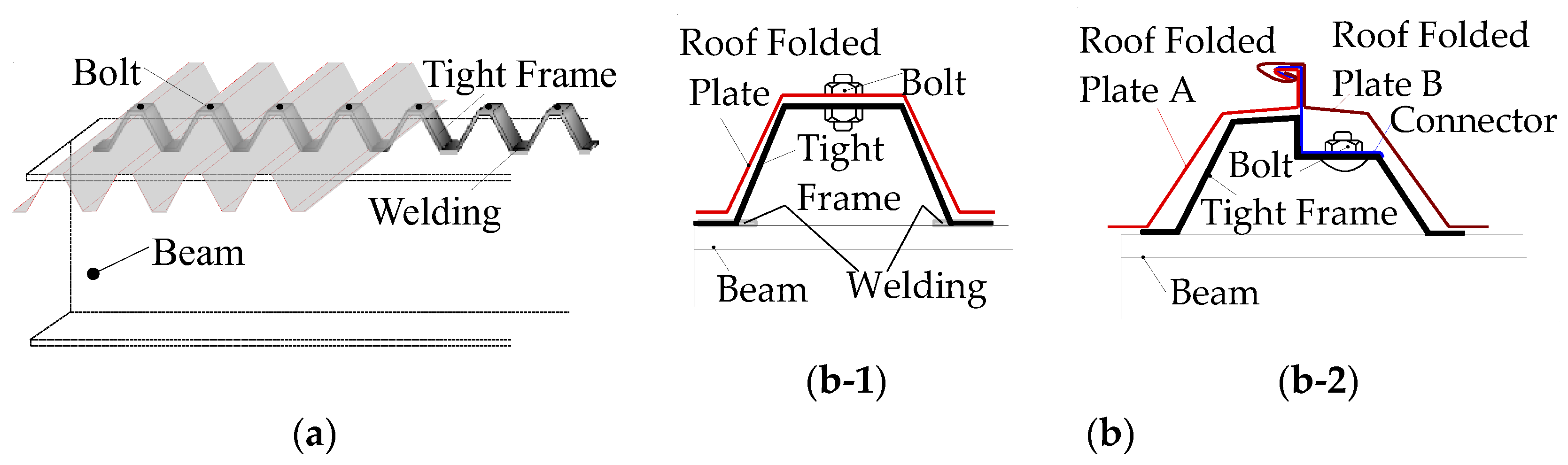
In the actual structural connection method (where tight frames are welded in a row along the length direction of the beam at the center of the top flange), the gap between the roof folded plate and the tight frame welded to the beam prevents torsional moments in the roof folded plate until the bottom flange of the roof folded plate contacts the top flange of the H steel beam, resulting in the non-exhibition of initial rotational stiffness kθ,1.
(3)
For specimens in which the tight frames are welded in two rows along the length direction at the top flange of the beam, a torsional moment is induced in the roof folded plate from the onset of loading, resulting in the initial rotational stiffness kθ,1 of the roof folded plate, being 2–3% of the theoretical rotational stiffness kθ,0.
(4)
For specimens in which connectors with stiffened blocks are utilized and both the top and bottom flanges of the roof folded plate are constrained, the initial rotational stiffness surpasses that of the other specimens. Specifically, the initial rotational stiffness kθ,1 of the roof folded plate amounts to approximately 12% of the theoretical rotational stiffness kθ,0.
(5)
When evaluating the lateral buckling capacity of continuously stiffened H beams using the buckling design capacities specified by the Japan code [46] and the Eurocode [47], it was observed that the design capacity outlined by the Japan code exceeded that of the Eurocode, even when the dimensionless slenderness ratio was equivalent.
(6)
Upon attaching the roof folded plates used in the experiments to the surveyed structures, it was observed that, in 16% of all of the structures, the torsional moment Mbr,1 occurring in the roof folded plates during the lateral buckling of the main beams was smaller than the torsional moment Mθ,1 at the onset of stiffness reduction, at which the initial rotational stiffness kθ,1 of the roof folded plates used in this study can be achieved. In contrast, in 62% of all structures, the maximum torsional moment Mθ,2, for which the secant rotational stiffness kθ,2 of the roof folded plates used in this study can be demonstrated, exceeds the torsional moment Mbr,2 occurring in the roof folded plates during the lateral buckling of the main beams. Thus, it can be inferred that the number of structures in which the roof folded plate exhibits the required performance against lateral buckling of the beams can be increased by utilizing the maximum torsional moment and the secant stiffness, rather than by relying on the initial stiffness and the bearing capacity at the onset of stiffness reduction, as the metrics for the holding performance of a roof folded plate.

Author Contributions

Conceptualization, Y.Y. and Y.K.; methodology, Y.Y. and Y.K.; software, Y.Y.; validation, Y.Y. and Y.K.; formal analysis, Y.Y. and Y.K.; investigation, Y.Y. and Y.K.; resources, Y.Y. and Y.K.; data curation, Y.Y.; writing—original draft preparation, Y.Y. and Y.K.; writing—review and editing, Y.Y. and Y.K.; visualization, Y.Y. and Y.K.; supervision, Y.Y. and Y.K.; project administration, Y.Y. and Y.K.; funding acquisition, Y.Y. and Y.K. All authors have read and agreed to the published version of the manuscript.

Funding

This research was funded by The Kajima Foundation’s Support Program for International Joint Research Activities (principal investigator: Yoshihiro Kimura) and JSPS KAKENHI (grant number 22K14369) (principal investigator: Yuki Yoshino). We express our deepest gratitude for their sincere support.

Data Availability Statement

The raw/processed data necessary to reproduce these findings cannot be shared at this time because the data also form part of an ongoing study.

Conflicts of Interest

The authors declare that they have no known competing financial interest or personal relationship that could have appeared to influence the work reported in this paper.

References

  1. Ishida, T.; Iyama, J.; Kishiki, S.; Shimada, Y.; Yamada, S.; Seike, T. Structural Damage to School Gymnasiums due to the 2016 Kumamoto Earthquake. J. Technol. Des. (Trans. AIJ) 2018, 58, 1313–1318. (In Japanese) [Google Scholar] [CrossRef]
  2. Suzuki, A.; Fujita, T.; Kimura, Y. Identifying damage mechanisms of gymnasium structure damaged by the 2011 Tohoku earthquake based on biaxial excitation. Structures 2022, 35, 1321–1338. [Google Scholar] [CrossRef]
  3. Kobayashi, F.; Sato, E.; Tomokiyo, E.; Noda, M.; Gavanski, E.; Takadate, Y.; Takamori, K.; Kimura, K.; Nakato, S.; Moriyama, H.; et al. Immediate Report on Wind Disasters Occurred by Typhoon 1915. J. Wind Eng. (JAWE) 2020, 45, 30–39. (In Japanese) [Google Scholar] [CrossRef]
  4. Akatsuka, T.; Tomokiyo, E. Investigation of Damage to Houses Caused by Typhoon JEBI and the Influence of Surrounding Environments on Its Occurrence. J. Wind Eng. (JAWE) 2020, 26, 96–101. (In Japanese) [Google Scholar] [CrossRef]
  5. Timoshenko, S.P. Beam without Lateral Support; American Society of Civil Engineers (ASCE): Reston, VA, USA, 1924; Volume 87. [Google Scholar]
  6. Bleich, F. Buckling Strength of Metal Structures; McGraw-Hill: New York, NY, USA, 1952; p. 405. [Google Scholar]
  7. Nethercot, D.A.; Rockey, K.C. A Unified Approach to the Elastic Lateral Buckling of Beams. Struct. Eng. 1971, 49, 96–107. [Google Scholar] [CrossRef]
  8. Suzuki, T. Lateral Buckling of Open Web. Trans. Archit. Inst. Jpn. (Trans. AIJ) 1960, 166, 537–540. (In Japanese) [Google Scholar]
  9. Wakabayashi, M.; Nakamura, T. Numerical Analysis of Lateral Buckling Strength of H-Shaped Steel Beams Subjected to End Moments and Uniformly Distributed Load. Trans. Archit. Inst. Jpn. (Trans. AIJ) 1973, 208, 7–13. (In Japanese) [Google Scholar] [CrossRef]
  10. Narayanan, R. Beam and Beam Columns-Stability and Strength; Applied Science Publisher: Boca Raton, FL, USA, 1983. [Google Scholar]
  11. Salvador, T.G. Lateral Buckling of Eccentrically Loaded I–Columns. Am. Soc. Civ. Eng. (ASCE) 1956, 121, 1163–1178. [Google Scholar] [CrossRef]
  12. Trahair, N.S. Laterally unsupported beams. Eng. Struct. 1996, 18, 759–768. [Google Scholar] [CrossRef]
  13. Lebastard, M.; Couchaux, M.; Bureau, A.; Hjiaj, M. Lateral-torsional buckling of uniform and tapered welded I-section beams. Eng. Struct. 2024, 303, 117301. [Google Scholar] [CrossRef]
  14. Yura, J.A. Fundamentals of beam bracing. Eng. J.-Am. Inst. Steel Constr. 2001, 38, 11–26. [Google Scholar] [CrossRef]
  15. Gengshu, T.; Shaofan, C. The elastic buckling of interbraced girders. J. Constr. Steel Res. 1989, 14, 87–105. [Google Scholar] [CrossRef]
  16. Kimura, Y.; Sugita, Y.; Yoshino, Y. Effect of lateral-rotational restraint of continuous braces on lateral buckling strength for H-shaped steel beams with compressive axial force and flexural moment. J. Struct. Constr. Eng. (Trans. AIJ) 2016, 81, 1321–1331. (In Japanese) [Google Scholar] [CrossRef]
  17. Kimura, Y.; Sato, Y. Effect of warping restraint of beams to column joint on lateral buckling behavior for H-shaped beams with continuous braces under gradient flexural moment. J. Struct. Constr. Eng. (Trans. AIJ) 2021, 86, 145–155. (In Japanese) [Google Scholar] [CrossRef]
  18. Kimura, Y.; Yoshino, Y. Required Bracing Capacity on Lateral Buckling Strength for H-Shaped Beams with Bracings. J. Struct. Constr. Eng. (Trans. AIJ) 2011, 76, 2143–2152. (In Japanese) [Google Scholar] [CrossRef]
  19. Kimura, Y.; Matsuo, T.; Yoshino, Y. Estimation of Elasto-Plastic Lateral Buckling Stress for H-Shaped Beams with Lateral-Rotational Braces on Subjected to Axial Force and Flexural Moment. J. Struct. Constr. Eng. (Trans. AIJ) 2014, 79, 1299–1308. (In Japanese) [Google Scholar] [CrossRef]
  20. Zhang, Z.; Kawai, R.; Kanao, I. Numerical Studies on Lateral Bracing Method with Effective Restraint on Out-of-Plane Deformation of Wide Flange Beam. J. Struct. Constr. Eng. (Trans. AIJ) 2014, 79, 323–329. (In Japanese) [Google Scholar] [CrossRef]
  21. Igawa, N.; Ikarashi, K.; Mitsui, K. Buckling Behavior of H-shaped Beam with Continuous Restraint Installed Transverse Stiffeners and Method for Deciding Stiffening Position. J. Struct. Constr. Eng. (Trans. AIJ) 2020, 85, 1491–1501. (In Japanese) [Google Scholar] [CrossRef]
  22. Nguyen, C.T.; Moon, J.; Lee, H.E. Lateral–torsional buckling of I-girders with discrete torsional bracings. J. Constr. Steel Res. 2010, 66, 170–177. [Google Scholar] [CrossRef]
  23. Ji, X.L.D.; Twizell, S.C.; Driver, R.G.; Imanpour, A. Lateral Torsional Buckling Response of Compact I-Shaped Welded Steel Girders. J. Struct. Eng. 2022, 148, 04022149. [Google Scholar] [CrossRef]
  24. Mohammadi, E.; Hosseini, S.S.; Rohanimanesh, M.S. Elastic lateral-torsional buckling strength and torsional bracing stiffness requirement for monosymmetric I-beams. Eng. Struct. 2016, 104, 116–125. [Google Scholar] [CrossRef]
  25. Nguyen, C.T.; Joo, H.S.; Moon, J.; Lee, H.E. Flexural-torsional buckling strength of I-girders with discrete torsional braces under various loading conditions. Eng. Struct. 2022, 36, 337–350. [Google Scholar] [CrossRef]
  26. Fukunaga, I.; Todaka, T.; Zhang, Z.; Kanao, I. Deformation Capacity of Wide Flange Beam with Lateral Bracings. J. Struct. Constr. Eng. (Trans. AIJ) 2022, 87, 372–380. (In Japanese) [Google Scholar] [CrossRef]
  27. Matsui, R.; Yamaura, Y.; Takeuchi, T. Lateral Bracing Requirements for H-Section Beams with Supports Attached to Top Flange Subjected to Cyclic Antisymmetric Moment. J. Struct. Constr. Eng. (Trans. AIJ) 2013, 78, 1485–1492. (In Japanese) [Google Scholar] [CrossRef]
  28. Idota, H.; Kato, Y.; Ono, T. Lateral Bracing Spacing and Strength of H- Shaped Steel Beams under Cyclic Loading. J. Struct. Constr. Eng. (Trans. AIJ) 2013, 78, 1989–1998. (In Japanese) [Google Scholar] [CrossRef]
  29. Ikarashi, K.; Ohnishi, Y.; Sano, T. Collapse Mode and Plastic Deformation Capacity of H-Shaped Beams with Continuous Restraint on Upper Flange. J. Struct. Constr. Eng. (Trans. AIJ) 2018, 83, 491–501. (In Japanese) [Google Scholar] [CrossRef]
  30. Kanao, I.; Nakashima, M.; Liu, D. Lateral Buckling Behavior and Lateral Bracing of Wide-Flange Beams Subjected Cyclic Loading. J. Struct. Constr. Eng. (Trans. AIJ) 2001, 66, 147–154. (In Japanese) [Google Scholar] [CrossRef] [PubMed]
  31. Bradford, M.A.; Gao, Z. Distortional buckling solutions for continuous composite beams. J. Struct. Eng. 1992, 118, 73–89. [Google Scholar] [CrossRef]
  32. Rossi, A.; Nicoletti, R.S.; de Souza, A.S.C.; Martins, C.H. Lateral distortional buckling in steel-concrete composite beams: A review. Structures 2020, 27, 1299–1312. [Google Scholar] [CrossRef]
  33. Egilmez, O.O.; Herman, R.S.; Helwig, T.A. Lateral stiffness of steel bridge I-girders braced by metal deck forms. J. Bridge Eng. 2009, 14, 17–25. [Google Scholar] [CrossRef]
  34. Suzuki, A.; Kimura, Y. Rotation capacity of I-shaped beam failed by local buckling in buckling-restrained braced frames with rigid beam-column connections. J. Struct. Eng. 2023, 149, 04022243. [Google Scholar] [CrossRef]
  35. Suzuki, A.; Suzuki, K.; Kimura, Y. Ultimate shear strength of perfobond shear connectors subjected to fully reversed cyclic loading. Eng. Struct. 2021, 248, 113240. [Google Scholar] [CrossRef]
  36. Tsuda, K.; Kido, M. Buckling Strength of Columns Braced Continuously with Varying Axial Force -Flexural Buckling of Compressive Flange of H-shaped Steel Restrained by Web or Slab-. J. Struct. Constr. Eng. (Trans. AIJ) 2013, 78, 1513–1521. (In Japanese) [Google Scholar] [CrossRef]
  37. Ikarashi, K.; Sano, T. Influence of Upper Flange Restraint Condition on Lateral Buckling Behavior of H-Shaped Beam. J. Struct. Constr. Eng. (Trans. AIJ) 2018, 83, 1063–1073. (In Japanese) [Google Scholar] [CrossRef]
  38. Kimura, Y.; Yoshino, Y.; Ogawa, J. Effect of Lateral-Rotational Restraint and Strength of Continuously Braces on Lateral Buckling Load for H-Shaped Beams. J. Struct. Constr. Eng. (Trans. AIJ) 2013, 78, 193–201. (In Japanese) [Google Scholar] [CrossRef]
  39. Kimura, Y.; Sugita, Y. Effect of Lateral-Rotational Restraint by Continuous Braces on Lateral Buckling Strength for H-Shaped Beams with Gradient Flexural Moment and Compressive Axial Force. J. Struct. Constr. Eng. (Trans. AIJ) 2017, 82, 1799–1809. (In Japanese) [Google Scholar] [CrossRef]
  40. Kimura, Y.; Yoshino, Y. Effect of Lateral and Rotational Restraint for Bracings on Lateral Buckling Load for H-Shaped Beams under Moment Gradient. J. Struct. Constr. Eng. (Trans. AIJ) 2014, 79, 761–770. (In Japanese) [Google Scholar] [CrossRef]
  41. Kimura, Y.; Yoshino, Y. Effect of Lateral-Rotational Restraint of Continuous Braces on Lateral Buckling Strength for H-Shaped Beams with Flexural Moment Gradient. J. Struct. Constr. Eng. (Trans. AIJ) 2016, 81, 1309–1319. (In Japanese) [Google Scholar] [CrossRef]
  42. Kimura, Y.; Miya, M.; Liao, W. Effect of Restraint for Continuous Braces on Lateral Buckling Load for H-Shaped Beams with Warping Restraint of Beams to Column Joint. J. Struct. Constr. Eng. (Trans. AIJ) 2018, 83, 1355–1363. (In Japanese) [Google Scholar] [CrossRef]
  43. Kimura, Y.; Miya, M. Effect of Warping Restraint of Beams to Column Joint on Lateral Buckling Behavior for H-Shaped Beams with Continuous Braces under Gradient Flexural Moment. J. Struct. Constr. Eng. (Trans. AIJ) 2019, 84, 1601–1611. (In Japanese) [Google Scholar] [CrossRef]
  44. Architectural Institute of Japan (AIJ). Recommendations for Stability Design of Steel Structures; Maruzen Publishing Co., Ltd.: Tokyo, Japan, 2012. [Google Scholar]
  45. Architectural Institute of Japan (AIJ). Design Standard for Structures–Based on Allowable Stress Concept; Maruzen Publishing Co., Ltd.: Tokyo, Japan, 2012. [Google Scholar]
  46. Architectural Institute of Japan (AIJ). Recommendation for Limit State Design of Steel Structures; Maruzen Publishing Co., Ltd.: Tokyo, Japan, 2011. [Google Scholar]
  47. Eurocode-3: Design of Steel Structures Part 1–1,1-3,1-5: General Rules and Rules for Buildings; European Committee for Standardization: Brussels, Belgium, 2005.
  48. Japan Metal Roofing Association. Standard of Steel Roofing (SSR); Japan Metal Roofing Association: Tokyo, Japan, 2007. [Google Scholar]
  49. JIS-A6514; Component for Metal Roof-Decks. Japanese Industrial Standards Committee: Tokyo, Japan, 2019. (In Japanese)
  50. Suzuki, A.; Abe, K.; Suzuki, K.; Kimura, Y. Cyclic behavior of perfobond-shear connectors subjected to fully reversed cyclic loading. J. Struct. Eng. 2021, 147, 04020355. [Google Scholar] [CrossRef]
  51. Yoshino, Y.; Liao, W.; Kimura, Y. Restraint effect on lateral buckling load of continuous braced H-shaped beams based on partial frame loading tests. J. Struct. Constr. Eng. (Trans. AIJ) 2022, 87, 634–645. (In Japanese) [Google Scholar] [CrossRef]
  52. Ikarashi, K.; Fujisawa, M.; Shimizu, N. Evaluation of Elastic Buckling Strength of Rectangular Corrugate Plate under Shear Loading. J. Struct. Constr. Eng. (Trans. AIJ) 2008, 73, 1883–1890. (In Japanese) [Google Scholar] [CrossRef]
  53. Ikarashi, K.; Nakano, S.; Shimizu, N. Evaluation of Shear Stiffness of Rectangular Corrugate Plate under Shear Loading. J. Struct. Constr. Eng. (Trans. AIJ) 2009, 74, 2327–2334. (In Japanese) [Google Scholar] [CrossRef]
  54. Shimizu, N.; Okada, T.; Ikarashi, K. A Study on Post Shear Buckling Behavior in Corrugated Steel Plate. J. Struct. Constr. Eng. (Trans. AIJ) 2010, 75, 1013–1020. (In Japanese) [Google Scholar] [CrossRef]
  55. Wei, X.; Li, G.; Xiao, L.; Zhou, L.; He, K.; Han, B. Shear strength reduction of trapezoidal corrugated steel plates with artificial corrosion pits. J. Constr. Steel Res. 2021, 180, 106583. [Google Scholar] [CrossRef]
  56. Wen, C.-B.; Guo, Y.-L.; Zuo, J.-Q.; Zhao, X.-Y. Strength design of prefabricated corrugated steel plate shear walls under combined compression and shear loads. J. Build. Eng. 2023, 65, 105790. [Google Scholar] [CrossRef]
  57. Elamary, A.S.; Saddek, A.B.; Alwetaishi, M. Effect of corrugated web on flexural capacity of steel beams. Int. J. Appl. Eng. Res 2017, 12, 470–481. [Google Scholar]
  58. Kubo, M.; Watanabe, K. Lateral-Torstional Buckling Capacity of Steel Girders with Corrugated Web Plates. Doboku Gakkai Ronbunshu A 2007, 63, 179–193. (In Japanese) [Google Scholar] [CrossRef]
  59. Watanabe, K.; Uchida, S.; Kubo, M. Shear buckling capacity of steel girders with corrugated webs. J. Struct. Eng. A 2007, 53A, 13–24. (In Japanese) [Google Scholar]
  60. Elkawas, A.A.; Hassanein, M.F.; Elchalakani, M. Lateral-torsional buckling strength and behaviour of high-strength steel corrugated web girders for bridge construction. Thin-Walled Struct. 2018, 122, 112–123. [Google Scholar] [CrossRef]
  61. Yi, J.; Gil, H.; Youm, K.; Lee, H. Interactive shear buckling behavior of trapezoidally corrugated steel webs. Eng. Struct. 2008, 30, 1659–1666. [Google Scholar] [CrossRef]
  62. Suzuki, A.; Liao, W.; Shibata, D.; Yoshino, Y.; Kimura, Y.; Shimoi, N. Structural damage detection technique of secondary building components using piezoelectric sensors. Build. 2023, 13, 2368. [Google Scholar] [CrossRef]
  63. Degtyarev, V.V. Flexural strength of steel decks with square and rectangular holes: Numerical studies. J. Constr. Steel Res. 2020, 172, 106241. [Google Scholar] [CrossRef]
  64. Degtyarev, V.V. Concentrated load distribution in corrugated steel decks: A parametric finite element study. Eng. Struct. 2020, 206, 110158. [Google Scholar] [CrossRef]
  65. Cho, H.; Ozaki, F.; Sato, Y.; Miyabayashi, K. Collapse Temperature of a Simple Supported Roof Member Using a Corrugated Steel Thin Plate. Steel Constr. Eng. 2024, 30, 63–74. (In Japanese) [Google Scholar] [CrossRef]
  66. Steel Deck Institute. Standard for Steel Roof Deck; Steel Deck Institute: Allison Park, PA, USA, 2017. [Google Scholar]
  67. Steel Deck Institute. Roof Deck Design Manual; Steel Deck Institute: Allison Park, PA, USA, 2012. [Google Scholar]
  68. Steel Deck Institute. Manual of Construction with Steel Deck; Steel Deck Institute: Allison Park, PA, USA, 2016. [Google Scholar]
  69. Otsu, T.; Takagi, J.; Okada, T.; Sato, Y.; Shoji, Y. In-Plane Shear Performance Evaluation of Roof Deck Plates Connected with Puddle Welding. J. Technol. Des. (Trans. AIJ) 2019, 60, 691–696. (In Japanese) [Google Scholar] [CrossRef]
  70. Takagi, J.; Shoji, Y.; Okada, T.; Sato, Y.; Otsu, T. Material Property of Roof Deck Steel Plates and Shear Behavior of Connections with Puddle Welding. J. Technol. Des. (Trans. AIJ) 2019, 59, 177–182. (In Japanese) [Google Scholar] [CrossRef]
  71. Kikitsu, H.; Ohkuma, T.; Okuda, Y.; Nishimura, H. Vulnerability of V-beam Steel Roofing Subjected to High Wind Hazard. J. Wind Eng. (JAWE) 2008, 20, 223–228. (In Japanese) [Google Scholar] [CrossRef]
  72. Coni, N.; Gipiela, M.L.; D’Oliveira, A.S.C.M.; Marcondes, P.V.P. Study of the mechanical properties of the hot dip galvanized steel and galvalume. J. Braz. Soc. Mech. Sci. Eng. 2009, 32, 319–326. [Google Scholar] [CrossRef]
  73. JIS Z 2241; Metallic Materials—Tensile Testing Method of Test at Room Temperature. Japan Industrial Standards (JIS): Tokyo, Japan, 2011.
Figure 1. Beam and roof folded plate for actual structures.
Buildings 14 01158 g001
Figure 2. Detail of beam–roof plate joint. (a) Beam length direction and (b) cross-sectional direction: (b-1) cross section A and (b-2) cross section B.
Buildings 14 01158 g002
Figure 3. Continuous stiffening for lateral buckling deformation of H beams. (a) Stresses in roof folded plates and (b) stiffness of the spring.
Buildings 14 01158 g003
Figure 4. Specimen and loading instrument.
Buildings 14 01158 g004
Figure 5. Detail of the specimen.
Buildings 14 01158 g005
Figure 6. Connector at the edge of the specimen (a–a′ line). (a) Elevation and (b) ground plan.
Buildings 14 01158 g006
Figure 7. Detail of connector (unit: mm). (a) Tight frame: (a-1) TF11 and (a-2) TF21. (b) Rigid block: (b-1) RA11, (b-2) RB12, (b-3) RA21, and (b-4) RA22.
Buildings 14 01158 g007
Figure 8. Strain measurement position. (a) Ground plan and (b) elevation.
Buildings 14 01158 g008
Figure 9. Hysteresis curves (torsional moment–angle). (a) Thickness, (b) shape of connector, (c) stresses in roof folded plates, (d) number of bolts, and (e) number of joints.
Buildings 14 01158 g009
Figure 10. Ultimate statement of specimens (+100 mm). (a) TF11-0.8, (b) RA11-0.8, (c) RB12−0.8, (d) TF21-0.8, (e) RA21-1.0, (f) RA22-1.0.
Buildings 14 01158 g010
Figure 11. Bending strain of top flange for CM (z = ±100 mm). (a) Tight frame and connector, (b) Number of bolts, and (c) number of joints.
Buildings 14 01158 g011
Figure 12. Deformation mechanism of bolted joints due to different connectors. (a) RA11, (b) RA21, (c) RA22.
Buildings 14 01158 g012
Figure 13. Axial strain of the roof folded plate’s top flange (z = +400 mm, +600 mm). (a) Tight frame and connector and (b) number of joints.
Buildings 14 01158 g013
Figure 14. Axial strain in z direction (at 0.1 My,r).
Buildings 14 01158 g014
Figure 15. Axial strain in x direction. (a) L side (−100 mm) and (b) R side (+100 mm).
Buildings 14 01158 g015
Figure 16. Rotational stiffness and torsional moment at (a) initial stiffness and at (b) secant stiffness.
Buildings 14 01158 g016
Figure 17. Required stiffness ratio and bracing moment ratio of roof folded plate at (a) initial stiffness and at (b) secant stiffness.
Buildings 14 01158 g017
Figure 18. Lateral buckling mode. (a) First Buckling mode and (b) second buckling mode.
Buildings 14 01158 g018
Figure 19. Image of the moment gradient generated in a beam.
Buildings 14 01158 g019
Figure 20. Lateral buckling strength curve [46,47].
Buildings 14 01158 g020
Figure 21. The procedure for computing the lateral buckling design capacity [38,46,47].
Buildings 14 01158 g021
Figure 22. The rate of increase for design bearing capacity in lateral buckling due to rotational stiffness at (a) initial stiffness and at (b) secant stiffness [46,47].
Buildings 14 01158 g022
Table 1. Details of specimens.
SpecimenRoof Folded Plate’s ThicknessRoof Folded Plate—Joint
MaterialPositionBolt
(mm)
TF11-0.80.8Tight frameOne lineOne bolt/top flange
TF11-1.01.0
TF21-0.80.8Two line
TF21-1.01.0
RA11-0.80.8Rigid block
(Type A)
One line
RB12-0.80.8Rigid block
(Type B)
One lineTwo bolt/top flange
RB12-1.01.0
RA21-0.80.8Rigid block
(Type A)
Two lineOne bolt/top flange
RA21-1.01.0
RA22-1.01.0Two bolt/top and bottom flange
Example of specimen name
Buildings 14 01158 i001
Table 2. Material properties of the roof folded plates.
Thickness
(mm)
Young’s Modulus
(×103 N/mm2)
Yield Strength
(N/mm2)
Ultimate Strength
(N/mm2)
0.8185322380
1.0178309383
Table 3. Summary of results.
SpecimenRotational StiffnessBracing Moment
TheoryInitialSecantInitialSecantYieldInitialMaximum
Equation (5)Equation (4)Equation (4)/Equation (5)Equation (2)Equation (1)/Equation (2)
kθ,0kθ,1kθ,2kθ,1/kθ,0kθ,2/kθ,0My,rMθ,1/My,rMθ,2/My,r
×102 kN/rad%%×102 kN/rad
TF11-0.837.75001271
TF11-1.045.3001528
TF21-0.837.751.080.362.850.9512710.070.33
TF21-1.045.31.470.473.251.0415280.110.39
RA11-0.837.751.510.544.011.4212710.180.5
RB12-0.837.751.600.574.241.515280.220.43
RB12-1.045.32.140.724.721.612710.240.52
RA21-0.837.751.150.533.041.415280.110.42
RA21-1.045.31.850.664.091.4512710.20.44
RA22-1.045.35.603.8512.368.515280.571.38
Table 4. Survey of steel structures in Japan with H beams as main beams.
Slenderness Ratio
of Main Beams
Percentage of Total (%)Number of Buildings
67 ≤ λb ≤ 20034.0206
200 < λb ≤ 30045.9278
300 <λb20.1122
Types of Small BeamsPercentage of Total (%)Number of Buildings
H94.4572
Angle and channel5.030
Not listed0.64
Types of Purlin MembersPercentage of Total (%)Number of Buildings
Channel (C,2C)89.3541
Angle (L,2L)1.06
T0.53
Not listed9.256
Types of Roofing MembersPercentage of Total (%)Number of Buildings
Roof folded plate2.817
Colored steel plate78.4476
Not listed18.8113
Buildings 14 01158 i002
Disclaimer/Publisher’s Note: The statements, opinions and data contained in all publications are solely those of the individual author(s) and contributor(s) and not of MDPI and/or the editor(s). MDPI and/or the editor(s) disclaim responsibility for any injury to people or property resulting from any ideas, methods, instructions or products referred to in the content.

