
Reduction in the Constrained Shrinkage and Crack Risk of Different-Strength-Level Concretes with Saturated Ceramsite
Abstract
:1. Introduction
2. Materials and Methods
2.1. Raw Materials
2.2. Proportioning
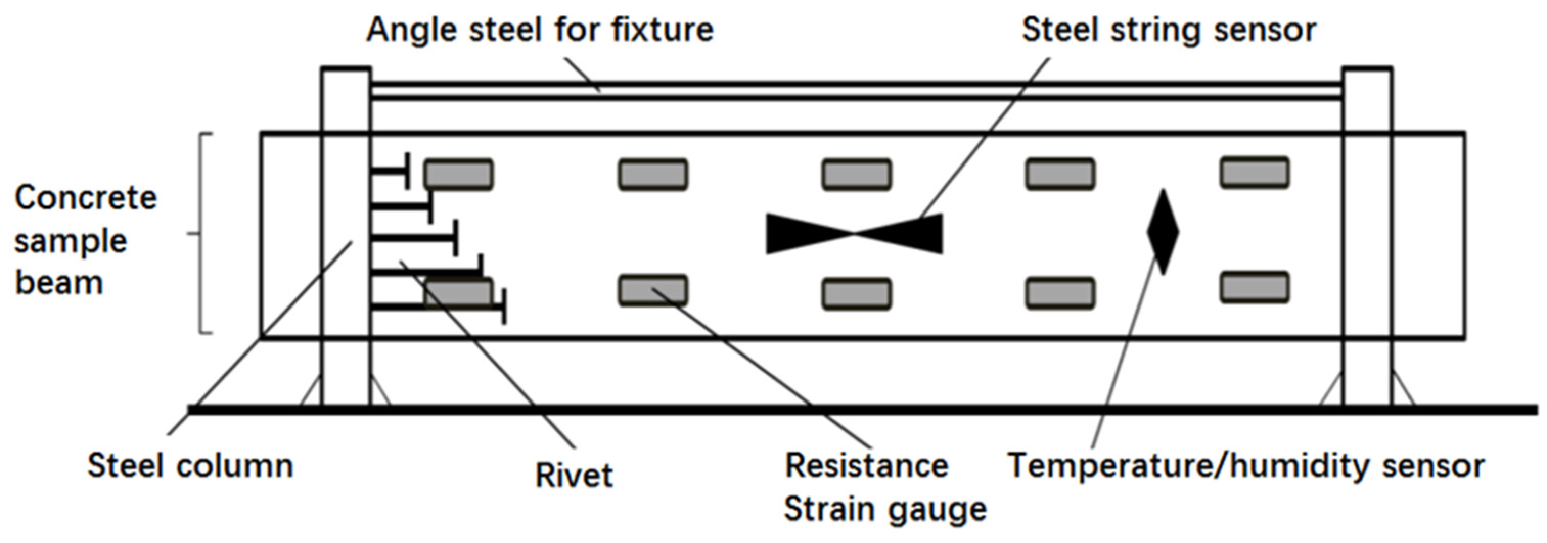
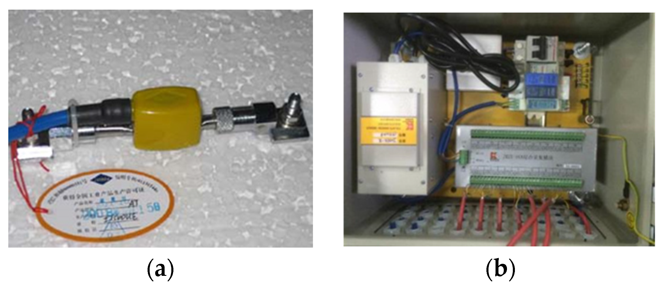
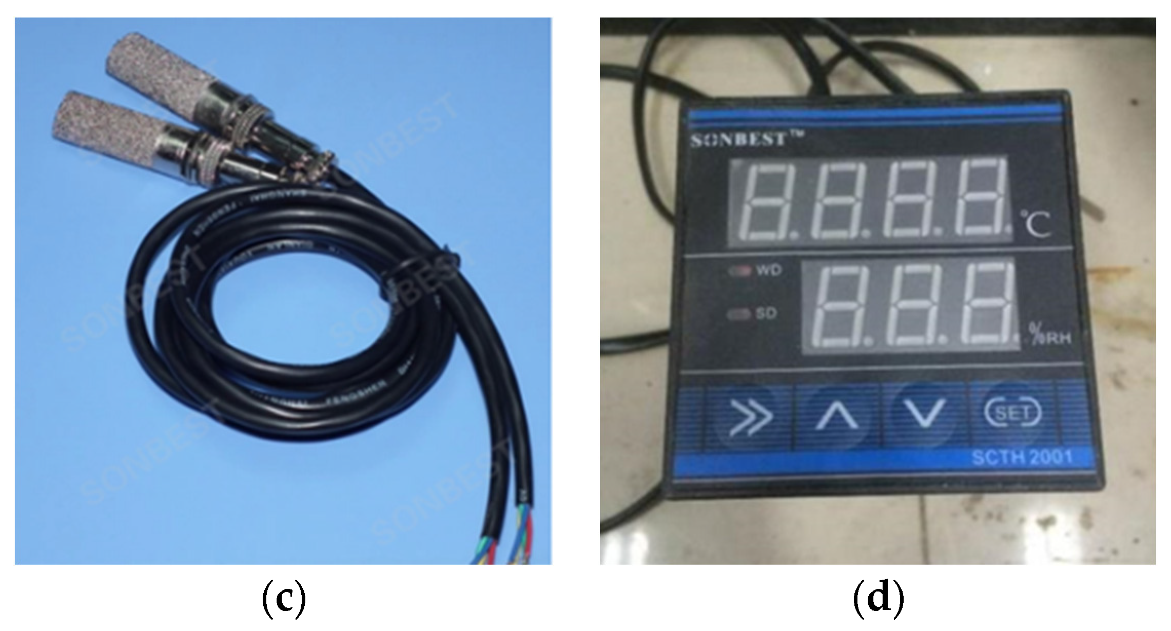
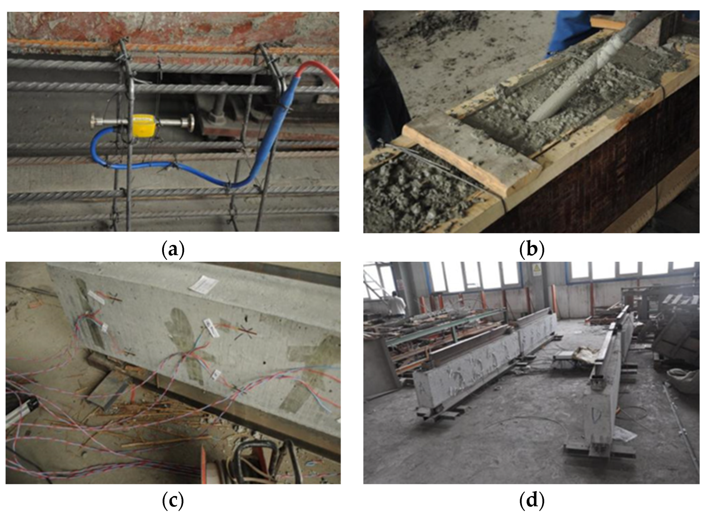
2.3. Test Methods
3. Results and Discussion
3.1. Compressive Strength of the Concrete Specimens
3.2. Hydration Temperature Rise Inside the Model Concrete Beams
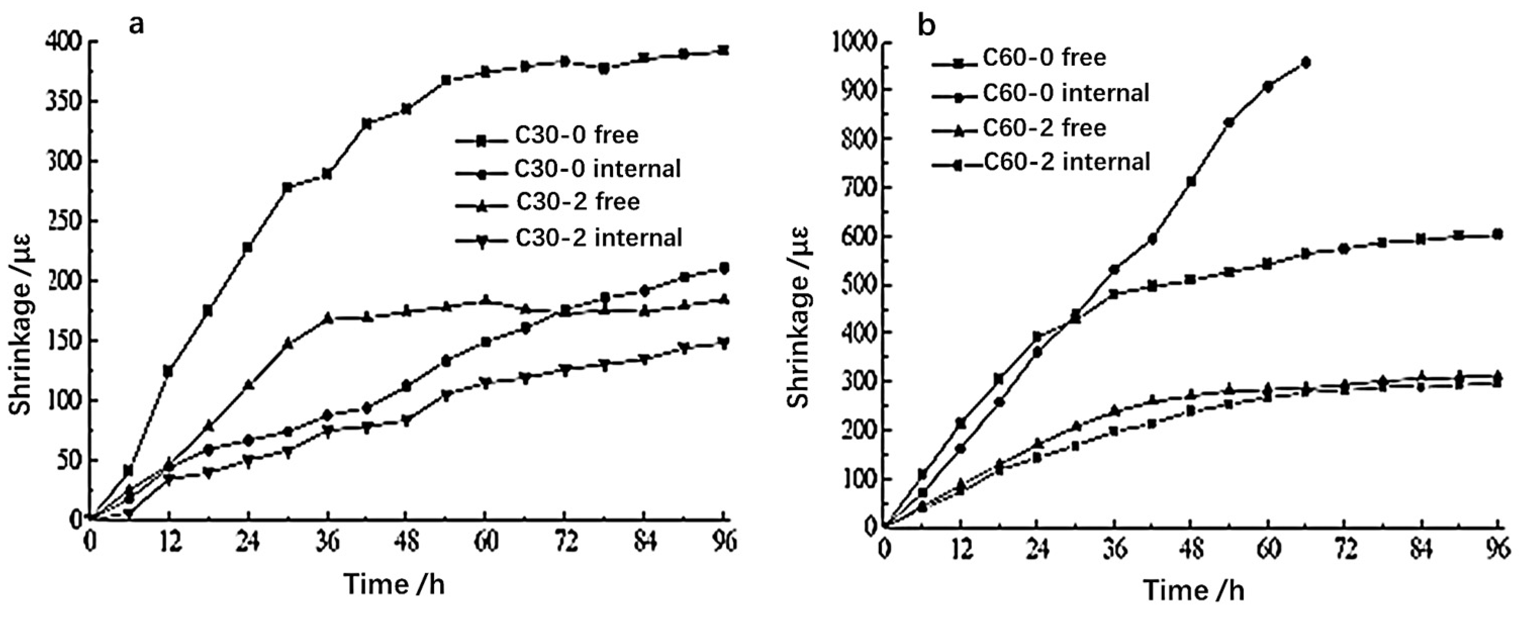
3.3. Early Shrinkage Behavior of Concrete Beams
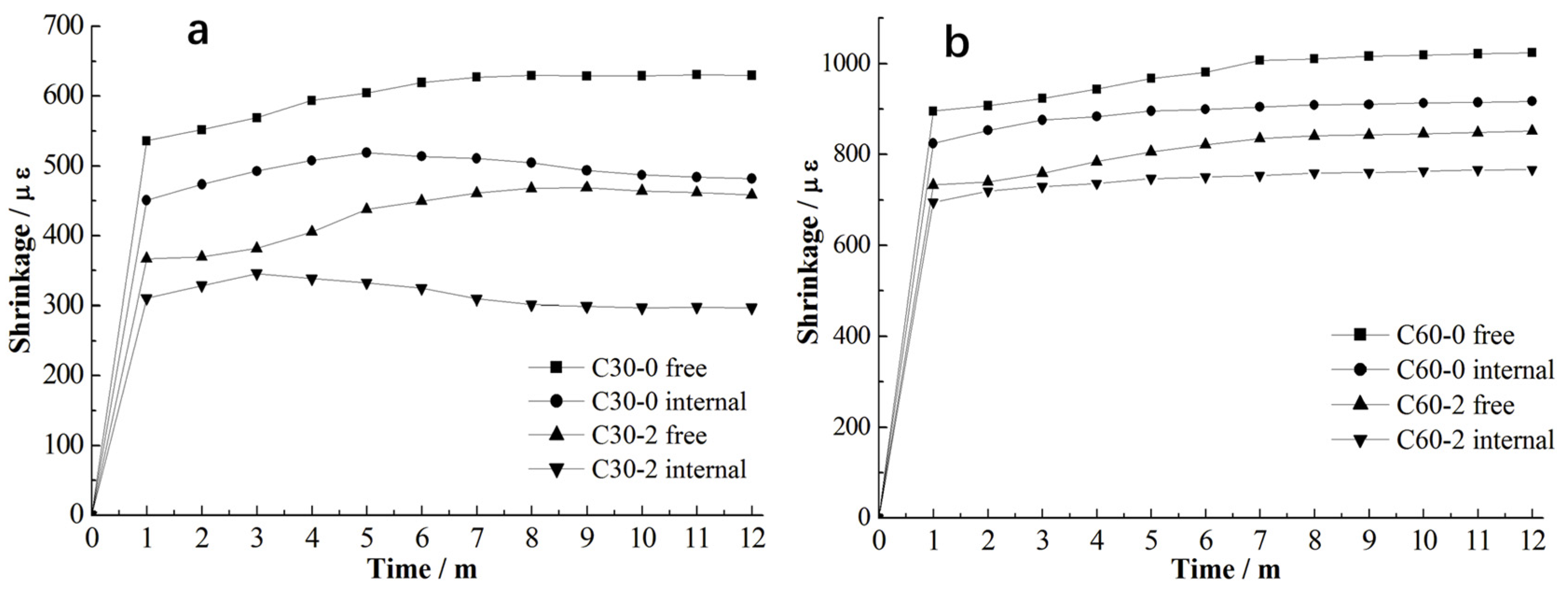
3.4. Long-Term Shrinkage of Concrete Beams
3.5. Long-Term Shrinkage Behavior of Concrete Beams Monitored by Surface-Attached Strain Sensors
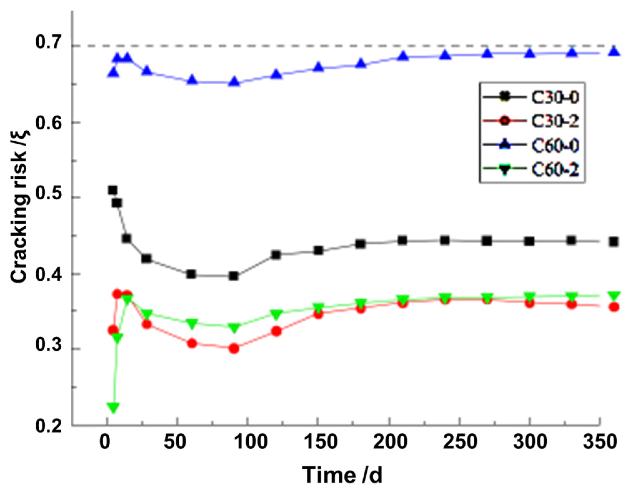
3.6. Assessment of the Cracking Risk of Model Beams
4. Conclusions
- (1)
- The inhibitory effect of saturated ceramsite on the hydration temperature rise of concrete was verified by tests on the model beam. With the incorporation of saturated ceramsite, the hydration temperature rise of concrete was reduced.
- (2)
- The constrained shrinkage behavior of internally cured concrete beams was revealed. Constraints may lead to internal stresses within the concrete beams as well as early-stage cracking. The internal curing effect of saturated ceramsite significantly reduced the confined shrinkage of concrete.
- (3)
- Both early-stage and long-term shrinkage development of the internally cured concrete beams were characterized. Most shrinkage of concrete beams over a one-year period was accomplished within the first month, after which it changed little. The internal curing effect significantly reduced the long-term shrinkage of the concrete beams.
- (4)
- Besides the method of embedded strain sensors, the surface-attached-sensor technique could also be used to monitor the shrinkage of the concrete beam. In this technique, the location of the strain sensor affected the measured shrinkage behavior greatly, and the largest shrinkage values were obtained in the middle of the concrete beam.
- (5)
- The maximum cracking risk of all the concrete beams within 12 months occurred in their early curing stage. For ordinary concretes, the higher the strength level, the greater the cracking risk. The incorporation of saturated ceramsite could significantly reduce the cracking risk of concretes, especially for higher-strength concrete.
Author Contributions
Funding
Data Availability Statement
Conflicts of Interest
Nomenclature
| SAPs | Super-absorbing polymers |
| LWA | Lightweight aggregate |
| C30 | Concrete with compressive strength level of ‘C30’ |
| C60 | Concrete with compressive strength level of ‘C60’ |
| ζ | Cracking risk of concrete |
| σs | Maximum tensile stress; |
| εs | Shrinkage value of concrete; |
| Ec | Elastic Modulus of concrete; |
| ft(t) | Tensile strength of concrete at moment t |
References
- Huang, X.; Liu, X.; Rong, H.; Yang, X.; Duan, Y.; Ren, T. Effect of Super-Absorbent Polymer (SAP) Incorporation Method on Mechanical and Shrinkage Properties of Internally Cured Concrete. Materials 2022, 15, 7854. [Google Scholar] [CrossRef] [PubMed]
- Lei, Y.; Yang, T.; Wu, D. Effect of biochar on mechanical and shrinkage properties of concrete. Sichuan Build. Mater. 2021, 47, 15–16. [Google Scholar]
- Zhang, G.; Ge, J.; Ding, Q. Preparation and Formation Mechanism of Lightweight Ultra-high Performance Concrete. J. Chin. Ceram. Soc. 2021, 49, 381–390. [Google Scholar]
- Kovler, K.; Souslikov, A.; Bentur, A. Pre-soaked light-weight aggregates as additives for internal curing of high strength concretes. Cem. Concr. Aggreg. 2004, 26, 131–138. [Google Scholar]
- Xia, H.; Zhang, G.; Zhao, X.; Liu, G.; Song, L.; Chen, H. Super-absorbent polymer for concrete internal curing agent and its latest research progress. Concrete 2020, 12, 85–89. [Google Scholar]
- Hu, S.; Zhang, G.; Yang, J. Effect of SAP on the Properties of Low Shrinkage Ultra High Performance Concrete. Concrete 2021, 54–58. [Google Scholar] [CrossRef]
- Liu, J.; Farzadnia, N.; Khayat, K.H.; Shi, C. Effects of SAP characteristics on internal curing of UHPC matrix. Constr. Build. Mater 2021, 280, 122530. [Google Scholar] [CrossRef]
- Morinaga, Y.; Akao, Y.; Fukuda, D.; Elakneswaran, Y. Delayed Absorption Superabsorbent Polymer for Strength Development in Concrete. Materials 2022, 15, 2727. [Google Scholar] [CrossRef] [PubMed]
- Lv, X.; Liu, Z.; Dong, Y. Comparative Study of the Effect of Super Absorbent Polymer (SAP) and Ceramsite on the Performance of Concrete. Bull. Chin. Ceram. Soc. 2019, 38, 246–252. [Google Scholar]
- Jóźwiak-Niedźwiedzka, D. Scaling resistance of high performance concretes containing a small portion of pre-wetted lightweight fine aggregate. Cem. Concr. Compos. 2005, 27, 709–715. [Google Scholar] [CrossRef]
- Cheng, S.; Shui, Z.; Yu, R.; Sun, T.; Zhang, X. Multiple influences of internal curing and supplementary cementitious materials on the shrinkage and microstructure development of reefs aggregate concrete. Constr. Build. Mater. 2017, 155, 522–530. [Google Scholar] [CrossRef]
- Henkensiefken, R.; Bentz, D.; Nantung, T.; Weiss, J. Volume change and cracking in internally cured mixtures made with saturated lightweight aggregate under sealed and unsealed conditions. Cem. Concr. Compos. 2009, 31, 427–437. [Google Scholar] [CrossRef]
- Ji, T.; Zheng, D.D.; Chen, X.F.; Lin, X.J.; Wu, H.C. Effect of prewetting degree of ceramsite on the early-age autogenous shrinkage of lightweight aggregate concrete. Constr. Build. Mater. 2015, 98, 102–111. [Google Scholar] [CrossRef]
- Cusson, D.; Hoogeveen, T. Internal curing of high-performance concrete with pre-soaked fine lightweight aggregate for prevention of autogenous shrinkage cracking. Cem. Concr. Res. 2008, 38, 757–765. [Google Scholar] [CrossRef]
- Guo, R.; Li, G.; An, M. Effect of internal curing techniques on the properties of high performance concrete of different strength classes. China Railw. Sci. 2015, 36, 24–29. [Google Scholar]
- Wang, X.F.; Fang, C.; Kuang, W.Q.; Li, D.W.; Han, N.X.; Xing, F. Experimental investigation on the compressive strength and shrinkage of concrete with pre-wetted light-weight aggregates. Constr. Build. Mater. 2017, 155, 867–879. [Google Scholar] [CrossRef]
- Wang, Y.; Qiu, J.; Zeng, C. Shrinkage and strength properties of coal gangue ceramsite lightweight aggregate concrete. Adv. Mater. Sci. Eng. 2020, 2020, 3575709. [Google Scholar] [CrossRef]
- Xie, J.; Liu, J.; Liu, F.; Wang, J.; Huang, P. Investigation of a new lightweight green concrete containing sludge ceramsite and recycled fine aggregates. J. Clean. Prod. 2019, 235, 1240–1254. [Google Scholar] [CrossRef]
- Fan, L.; Zhang, Z.; Yu, Y.; Li, P.; Cosgrove, T. Effect of elevated curing temperature on ceramsite concrete performance. Constr. Build. Mater. 2017, 153, 423–429. [Google Scholar] [CrossRef]
- Gong, J.; Zeng, W.; Zhang, W. Influence of shrinkage reducing agent and polypropylene fiber on shrinkage of ceramsite concrete. Constr. Build. Mater. 2018, 159, 155–163. [Google Scholar] [CrossRef]
- Shen, Y.; Ma, X.; Huang, J.; Hao, F.; Lv, J.; Shen, M. Near-zero restrained shrinkage polymer concrete incorporating ceramsite and waste rubber powder. Cem. Concr. Compos. 2020, 110, 103584. [Google Scholar] [CrossRef]
- Shen, Y.; Huang, J.; Ma, X.; Hao, F.; Lv, J. Study on the free shrinkage of lightweight polymer concrete incorporating waste rubber powder and ceramsite. Compos. Struct. 2020, 242, 112152. [Google Scholar] [CrossRef]
- Lin, J.; Lu, J. Experimental Study on Effect for Internal Curing of Porous Saturated Aggregate on the Crack Resistance and Strength of Concrete. Fly Ash Compr. Util. 2020, 34, 68–73. [Google Scholar]
- Yang, J.; Tang, Y.; Yu, J. Experimental study of cast-in-situ all lightweight foamed concrete used by shale ceramsite. Ind. Constr. 2017, 47, 133–140. [Google Scholar]
- GB/T50082-2009; Standard for Test Methods of Long-Term Performance and Durability of Ordinary Concrete. China Architecture & Building Press: Beijing, China, 2009.
- GB/T50081-2002; Standard for Test Method of Mechanical Properties on Ordinary Concrete. China Architecture & Building Press: Beijing, China, 2003.
- Bazant, Z.P.; Murphy, W.P. Creep and shrinkage prediction model for analysis and design of concrete structures-model B3. Mater. Struc. 1995, 28, 357–365. [Google Scholar]
- Bazant, Z.P.; Baweja, S. Justification and refinements of model B3 for concrete creep and shrinkage 1. statistics and sensitivity. Mater. Struc. 1995, 28, 415–430. [Google Scholar] [CrossRef]
- Liang, T.; Luo, P.; Mao, Z.; Huang, X.; Deng, M.; Tang, M. Effect of Hydration Temperature Rise Inhibitor on the Temperature Rise of Concrete and Its Mechanism. Materials 2023, 16, 2992. [Google Scholar] [CrossRef]
- Li, H.; Liu, J.; Wang, Y.; Yao, T.; Tian, Q.; Li, S. Deformation and cracking modeling for early-age sidewall concrete based on the multi-field coupling mechanism. Constr. Build. Mater. 2015, 88, 84–93. [Google Scholar] [CrossRef]
- Ishida, T.; Maekawa, K.; Kishi, T. Enhanced modeling of moisture equilibrium and transport in cementitious materials under arbitrary temperature and relative humidity history. Cem. Concr. Res. 2007, 4, 565–578. [Google Scholar] [CrossRef]
- Gao, Y.; Zhang, J.; Hou, D. Calculation of moisture induced stress and evaluation of cracking risk in early age concrete. Eng. Mech. 2012, 29, 121–128. [Google Scholar]
- Wang, J.; Yan, P. Analyzing of Cracking Risk of Early-age Concrete Structure. J. Basic Sci. Eng. 2006, 2, 262–267. [Google Scholar]


| Raw Material | Fineness (cm2/g) | Time of Initial Condensation (min) | Time of Final Condensation (min) | Standardized Consistency (%) | Heat Loss (%) |
|---|---|---|---|---|---|
| C30 | 3400 | 160 | 220 | 27 | 0.5 |
| C60 | 3790 | 122 | 160 | 29 | 0.61 |
| Raw Material | Density (g/cm3) | Specific Surface Area (cm2/g) | Cl− (%) | SO3 (%) |
|---|---|---|---|---|
| fly ash | 2.1 | 350 | 0.005 | 0.9 |
| mineral powder | 2.9 | 461 | 0.006 | 1 |
| Raw Material | Apparent Density (g/cm3) | Bulk Density (g/cm3) | Clay Content (%) |
|---|---|---|---|
| Fine aggregate | 2.62 | 1.62 | 0.1 |
| Coarse aggregate | 2.68 | 1.5 | 0.8 |
| Sample | Cement | Aggregate | Gravel | Fly Ash | Mineral Powder | Silicon Powder | Water | Water Reducing Agent | Saturated Ceramsite |
|---|---|---|---|---|---|---|---|---|---|
| C30-0 | 216 | 1117 | 809 | 108 | 36 | 0 | 140 | 9 | 0 |
| C30-1 | 216 | 1005 | 809 | 108 | 36 | 0 | 140 | 9 | 34 |
| C30-2 | 216 | 894 | 809 | 108 | 36 | 0 | 140 | 9 | 67 |
| C30-3 | 216 | 782 | 809 | 108 | 36 | 0 | 140 | 9 | 101 |
| C60-0 | 312 | 998 | 722 | 104 | 52 | 52 | 130 | 12.5 | 0 |
| C60-1 | 312 | 898 | 722 | 104 | 52 | 52 | 130 | 12.5 | 30 |
| C60-2 | 312 | 898 | 722 | 104 | 52 | 52 | 130 | 12.5 | 60 |
| C60-3 | 312 | 789 | 722 | 104 | 52 | 52 | 130 | 12.5 | 90 |
| Sample | Compressive Strength at 7 Days (MPa) | Compressive Strength at 28 Days (MPa) | Compressive Strength at 90 Days (MPa) |
|---|---|---|---|
| C30-0 | 31.11 ± 1.08 | 42.22 ± 0.46 | 46.27 ± 1.61 |
| C30-1 | 28.13 ± 2.16 | 37.97 ± 1.71 | 42.77 ± 2.47 |
| C30-2 | 25.11 ± 1.88 | 33.72 ± 1.42 | 39.27 ± 1.63 |
| C30-3 | 22.12 ± 1.35 | 29.47 ± 3.15 | 35.77 ± 1.87 |
| C60-0 | 69.57 ± 3.53 | 82.62 ± 2.14 | 87.63 ± 3.04 |
| C60-1 | 68.37 ± 5.18 | 80.57 ± 3.32 | 84.83 ± 4.67 |
| C60-2 | 67.17 ± 2.81 | 78.52 ± 2.97 | 82.03 ± 3.52 |
| C60-3 | 65.97 ± 4.07 | 76.47 ± 3.33 | 79.23 ± 4.73 |
| Sample | The Fitted Equation |
|---|---|
| C30-0 | F(x) = (48.88x + 0.7329)/(x + 3.516) |
| C30-2 | F(x) = (42.38x − 1.84)/(x + 5.133) |
| C60-0 | F(x) = (91.3x − 2.462)/(x + 2.371) |
| C60-2 | F(x) = (86.92x − 3.41)/(x + 2.581) |
Disclaimer/Publisher’s Note: The statements, opinions and data contained in all publications are solely those of the individual author(s) and contributor(s) and not of MDPI and/or the editor(s). MDPI and/or the editor(s) disclaim responsibility for any injury to people or property resulting from any ideas, methods, instructions or products referred to in the content. |
© 2024 by the authors. Licensee MDPI, Basel, Switzerland. This article is an open access article distributed under the terms and conditions of the Creative Commons Attribution (CC BY) license (https://creativecommons.org/licenses/by/4.0/).
Share and Cite
Nan, P.; Zuo, B.; Han, S.; Huang, T.; Xiao, E. Reduction in the Constrained Shrinkage and Crack Risk of Different-Strength-Level Concretes with Saturated Ceramsite. Buildings 2024, 14, 1526. https://doi.org/10.3390/buildings14061526
Nan P, Zuo B, Han S, Huang T, Xiao E. Reduction in the Constrained Shrinkage and Crack Risk of Different-Strength-Level Concretes with Saturated Ceramsite. Buildings. 2024; 14(6):1526. https://doi.org/10.3390/buildings14061526
Chicago/Turabian StyleNan, Pengpeng, Bin Zuo, Song Han, Tao Huang, and Erpo Xiao. 2024. "Reduction in the Constrained Shrinkage and Crack Risk of Different-Strength-Level Concretes with Saturated Ceramsite" Buildings 14, no. 6: 1526. https://doi.org/10.3390/buildings14061526