
The Creation of Geotechnical Seismic Isolation from Materials with Damping Properties for the Protection of Architectural Monuments

 ,
,  and
and
Abstract
1. Introduction
2. Materials and Methods
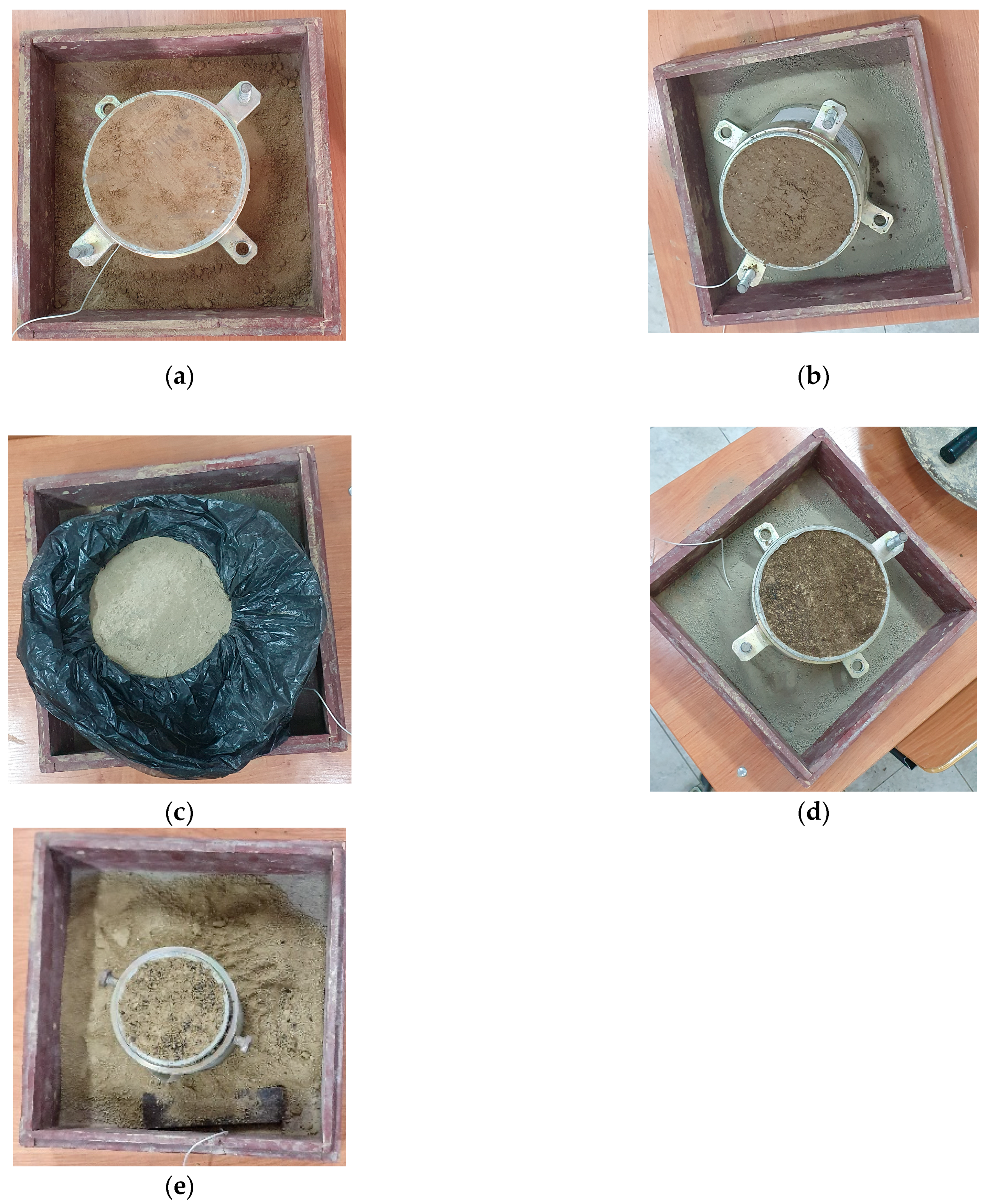
2.1. Materials
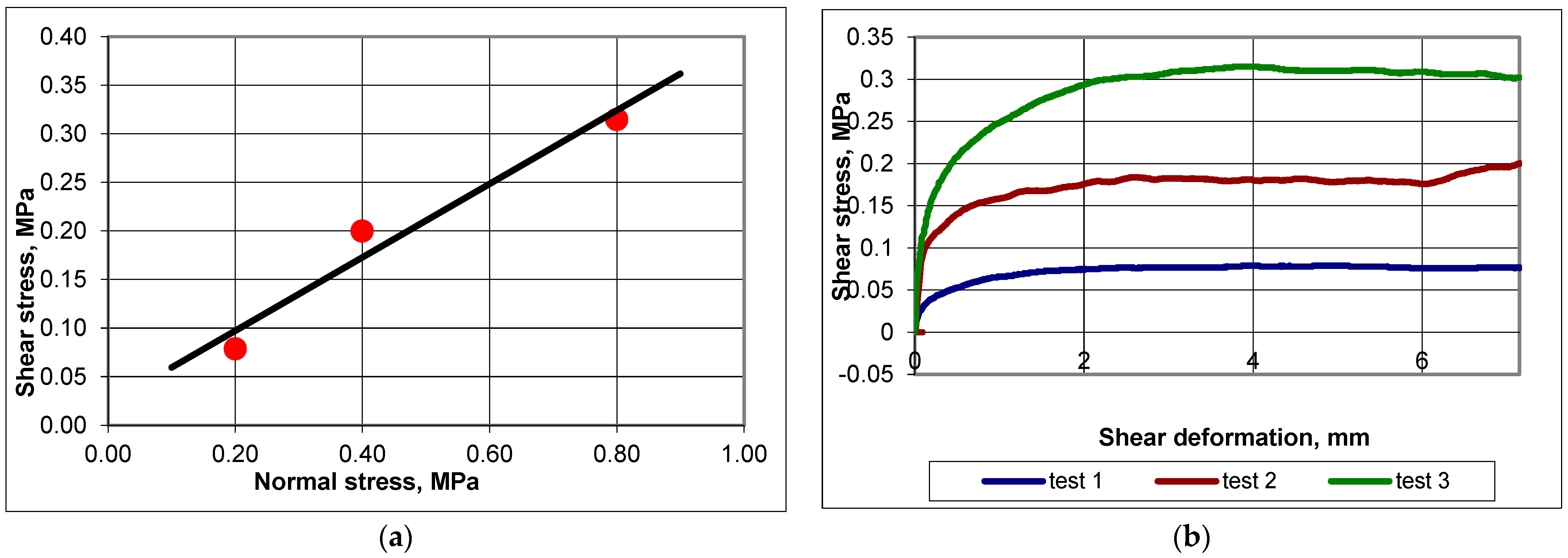
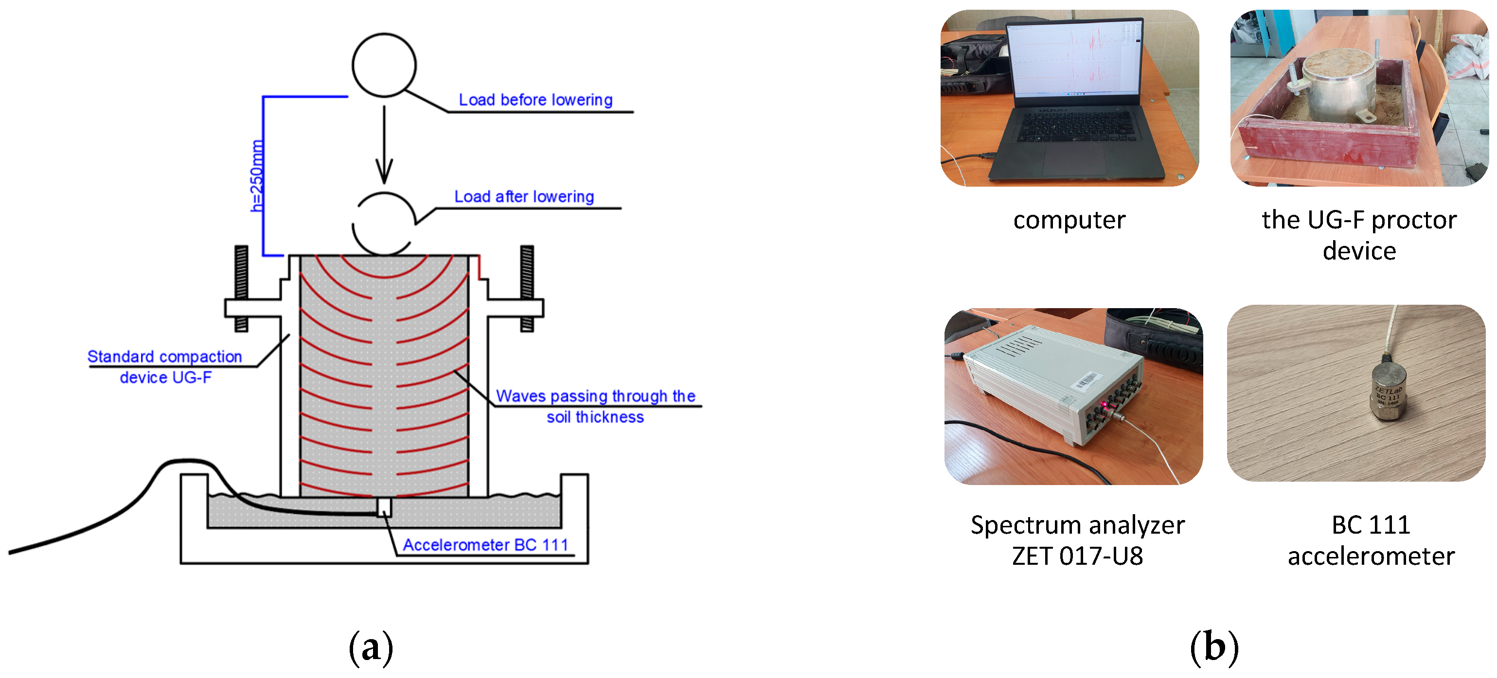
2.2. Methods
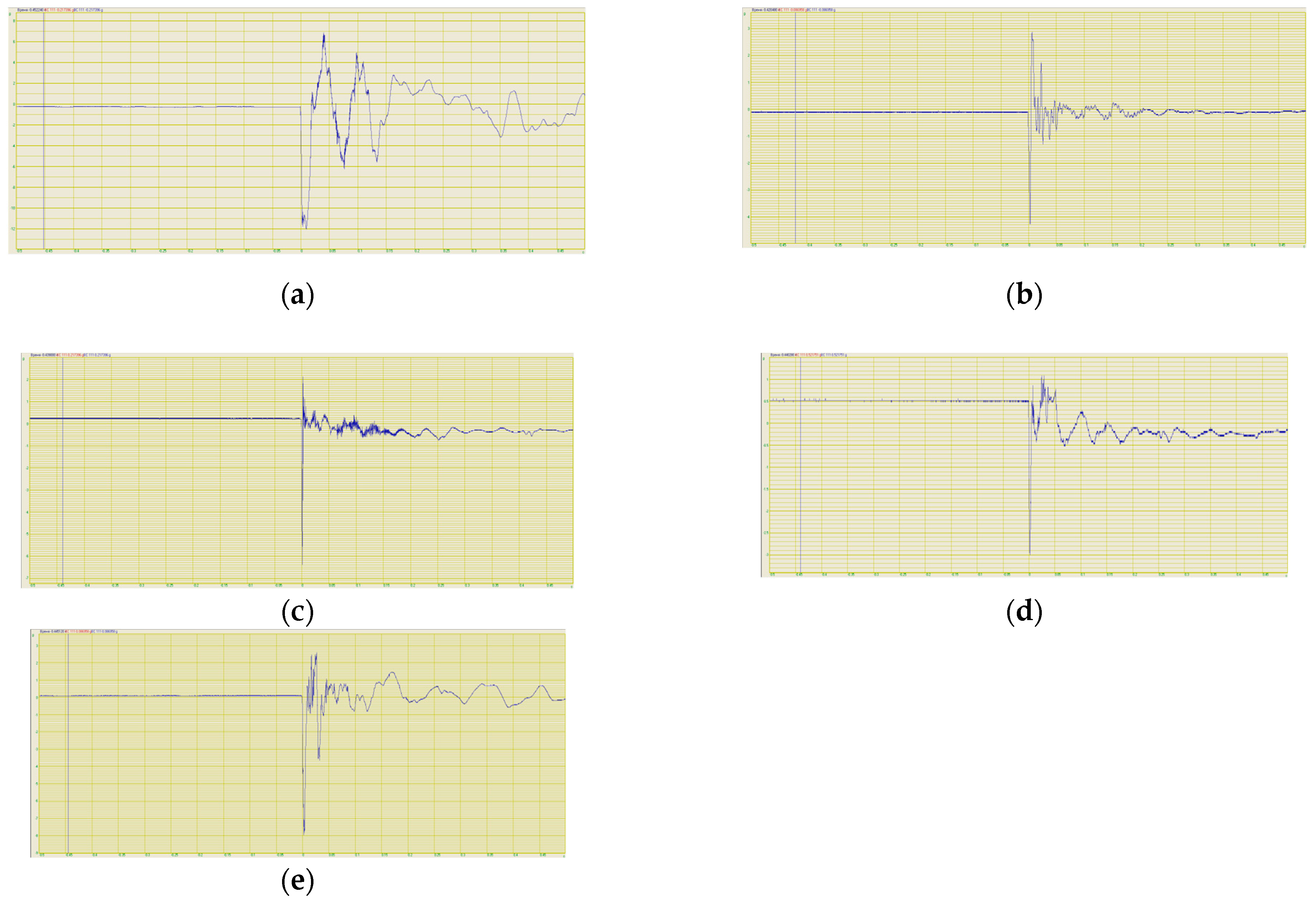
2.2.1. The Theory of Recording Earthquakes with Accelerometers
2.2.2. Experimental Program
3. Results
4. Discussion
5. Conclusions
6. Patents
- Besimbaev, E.T.; Zhautikov, E.Z.; Shokbarov, Y.M.; Irgibaev, T.I.; Besimbaeva, L.E.; Nietbay, S.E. Screen for protecting buildings and structures from seismic shocks during earthquakes and influence of man-made sources of vibrations, 36536, E02D 31/08, KZ, 5 January 2024, bulletin No. 1, 5 https://gosreestr.kazpatent.kz/Invention/DownLoadFilePdf?patentId=367433&lang=ru (accessed on 5 January 2024).
- Besimbaev, E.T.; Zhambakina, Z.M.; Irgibaev, T.I.; Besimbaeva, L.E.; Nietbay, S.E.; Screen for protecting buildings and structures from seismic shocks during earthquakes and influence of man-made sources of vibrations 36537, E02D 31/08, KZ, 5 January 2024, bulletin No. 1, 5 https://gosreestr.kazpatent.kz/Invention/DownLoadFilePdf?patentId=367434&lang=ru (accessed on 5 January 2024).
Author Contributions
Funding
Data Availability Statement
Acknowledgments
Conflicts of Interest
References
- Sendai Framework for Disaster Risk Reduction 2015–2030. 2015, 37. Available online: https://www.preventionweb.net/files/43291_sendaiframeworkfordrren.pdf (accessed on 1 January 2015).
- Calvi, P.M.; Calvi, G.M. Historical Development of Friction-Based Seismic Isolation Systems. Soil Dyn. Earthq. Eng. 2018, 106, 14–30. [Google Scholar] [CrossRef]
- Belash, T.; Begaliev, U.; Orunbaev, S.; Abdybaliev, M. On the Efficiency of Use of Seismic Isolation in Antiseismic Construction. Am. J. Environ. Sci. Eng. 2019, 3, 66–74. [Google Scholar] [CrossRef]
- Avossa, A.M.; Pianese, G. Damping Effects on the Seismic Response of Base-Isolated Structures with LRB Devices. Ing. Sismica 2017, 34, 3–30. Available online: http://ingegneriasismica.org/3782-2/ (accessed on 1 January 2017).
- Castaldo, P.; Ripani, M. Optimal Design of Single Concave Sliding Bearings for Isolated Structures Considering Intermediate Isolation Degrees. Ing. Sismica 2017, 34, 5–23. Available online: https://www.semanticscholar.org/paper/Optimal-design-of-single-concave-sliding-bearings-Castaldo-Ripani/2249e6e1cddbab541df40c4d5e0d2f70ccee97c7 (accessed on 1 January 2017).
- Petrone, G.; Ferrentino, T.; Alfano, G. Influence of PGA/PGV Ratio on the Seismic Reliability of Base-Isolated Systems with FPS. Ing. Sismica 2017, 34, 39–62. Available online: http://ingegneriasismica.org/2017/09/ (accessed on 1 January 2017).
- Calvi, P.M.; Moratti, M.; Calvi, G.M. Seismic Isolation Devices Based on Sliding between Surfaces with Variable Friction Coefficient. Earthq. Spectra 2016, 32, 2291–2315. [Google Scholar] [CrossRef]
- Chalhoub, M.S.; Kelly, J.M. Sliders and Tension Controlled Reinforced Elastomeric Bearings Combined for Earthquake Isolation. Earthq. Eng. Struct. Dyn. 1990, 19, 333–344. [Google Scholar] [CrossRef]
- Chen, Y.; Ahmadi, G. Stochastic Earthquake Response of Secondary Systems in Base-isolated Structures. Earthq. Eng. Struct. Dyn. 1992, 21, 1039–1057. [Google Scholar] [CrossRef]
- Griffith, M.C.; Aiken, I.D.; Kelly, J.M. Displacement Control and Uplift Restraint for Base-Isolated Structures. J. Struct. Eng. 1990, 116, 1135–1148. [Google Scholar] [CrossRef]
- Jangid, R.S.; Datta, T.K. Nonlinear Response of Torsionally Coupled Base Isolated Structure. J. Struct. Eng. 1994, 120, 1–22. [Google Scholar] [CrossRef]
- Awwad, T.; Donia, M. The Efficiency of Using a Seismic Base Isolation System for a 2D Concrete Frame Founded upon Improved Soft Soil with Rigid Inclusions. Earthq. Eng. Eng. Vib. 2016, 15, 49–60. [Google Scholar] [CrossRef]
- Forcellini, D. Assessment of Geotechnical Seismic Isolation (GSI) as a Mitigation Technique for Seismic Hazard Events. Geosciences 2020, 10, 222. [Google Scholar] [CrossRef]
- Celebi, M. Design of Seismic Isolated Structures: From Theory to Practice. Earthq. Spectra 2000, 16. [Google Scholar] [CrossRef]
- Giuliani, G.C. Structural Design, Analysis and Full-Scale Tests of Seismically Isolated Buildings. Eng. Struct. 1993, 15, 102–116. [Google Scholar] [CrossRef]
- Zhang, C.; Ali, A. The Advancement of Seismic Isolation and Energy Dissipation Mechanisms Based on Friction. Soil Dyn. Earthq. Eng. 2021, 146, 106746. [Google Scholar] [CrossRef]
- Al-Hussaini, T.M.; Ahmad, S. Design of Wave Barriers for Reduction of Horizontal Ground Vibration. J. Geotech. Eng. 1991, 117, 616–636. [Google Scholar] [CrossRef]
- Bernal-Sanchez, J.; Leak, J.; Barreto, D. Rubber-Soil Mixtures: Use of Grading Entropy Theory to Evaluate Stiffness and Liquefaction Susceptibility. Bull. Earthq. Eng. 2023, 21, 3777–3796. [Google Scholar] [CrossRef]
- Ali, H.-E.M.; Abdel-Ghaffar, A.M. Modeling of Rubber and Lead Passive-Control Bearings for Seismic Analysis. J. Struct. Eng. 1995, 121, 1134–1144. [Google Scholar] [CrossRef]
- Abate, G.; Fiamingo, A.; Massimino, M.R. An Eco-Sustainable Innovative Geotechnical Technology for the Structures Seismic Isolation, Investigated by FEM Parametric Analyses. Bull. Earthq. Eng. 2023, 21, 4851–4875. [Google Scholar] [CrossRef]
- Xiong, W.; Tsang, H.H.; Lo, S.H.; Shang, S.; Wang, H.; Zhou, F. Geotechnical Seismic Isolation System—Experimental Study. Adv. Mater. Res. 2011, 163, 4449–4453. Available online: https://www.scientific.net/AMR.163-167.4449 (accessed on 1 January 2011).
- Wu, M.; Tian, W.; Liu, F.; Yang, J. Dynamic Behavior of Geocell-Reinforced Rubber Sand Mixtures under Cyclic Simple Shear Loading. Soil Dyn. Earthq. Eng. 2023, 164, 107595. [Google Scholar] [CrossRef]
- Abate, G.; Fiamingo, A.; Massimino, M.R.; Pitilakis, D. FEM Investigation of Full-Scale Tests on DSSI, Including Gravel-Rubber Mixtures as Geotechnical Seismic Isolation. Soil Dyn. Earthq. Eng. 2023, 172, 108033. [Google Scholar] [CrossRef]
- Dhanya, J.S.; Boominathan, A.; Banerjee, S. Investigation of Geotechnical Seismic Isolation Bed in Horizontal Vibration Mitigation. J. Geotech. Geoenviron. Eng. 2022, 148, 04022108. [Google Scholar] [CrossRef]
- Kuvat, A.; Sadoglu, E. Dynamic Properties of Sand-Bitumen Mixtures as a Geotechnical Seismic Isolation Material. Soil Dyn. Earthq. Eng. 2020, 132, 106043. [Google Scholar] [CrossRef]
- Banović, I.; Radnić, J.; Grgić, N. Numerical Model for Dynamic Analysis of Structures with Seismic Base Isolation Using A Layer of Stone Pebbles. Ing. Sismica 2021, 38, 37–65. Available online: https://ingegneriasismica.org/numerical-model-for-dynamic-analysis-of-structures-with-seismic-base-isolation-using-a-layer-of-stone-pebbles/ (accessed on 1 January 2011).
- Talal, A.; Hassan, A. Seismic Design of Embankments—Numerical and Analytical Study. Int. J. Comput. Civ. Struct. Eng. 2022, 18, 51–61. [Google Scholar] [CrossRef]
- Awwad, T.; Donia, M.; Awwad, L. Effect of a Stiff Thin Foundation Soil Layer’s Depth on Dynamic Response of an Embankment Dam. Procedia Eng. 2017, 189, 525–532. [Google Scholar] [CrossRef]
- Dudchenko, A.V.; Dias, D.; Kuznetsov, S.V. Vertical Wave Barriers for Vibration Reduction. Arch. Appl. Mech. 2021, 91, 257–276. [Google Scholar] [CrossRef]
- Kuznetsov, S.V.; Nafasov, A.E. Horizontal Acoustic Barriers for Protection from Seismic Waves. Adv. Acoust. Vib. 2011, 2011, 150310. [Google Scholar] [CrossRef]
- Gatto, M.P.A.; Montrasio, L. The Geotechnical Seismic Isolation of Historical Buildings through Polyurethane Injections: A Numerical Study. In Geotechnical Engineering for the Preservation of Monuments and Historic Sites III; CRC Press: Boca Raton, FL, USA, 2022; Available online: https://www.taylorfrancis.com/chapters/oa-edit/10.1201/9781003308867-71/geotechnical-seismic-isolation-historical-buildings-polyurethane-injections-numerical-study-gatto-montrasio (accessed on 1 January 2022).
- Bessimbayev, Y.; Zhambakina, Z.; Niyetbay, S. Ensuring the seismic resistance of a building using a geotechnical seismic insulating screen. East.-Eur. J. Enterp. Technol. 2022, 3, 59–67. [Google Scholar] [CrossRef]
- Abate, G.; Chiaro, G.; Fiamingo, A. Laboratory Tests on Gravel-Rubber Mixtures (GRM): FEM Modelling Versus Experimental Observations. In Geotechnical Engineering in the Digital and Technological Innovation Era; Springer Series in Geomechanics and Geoengineering; Springer: Berlin/Heidelberg, Germany, 2023; Available online: https://link.springer.com/chapter/10.1007/978-3-031-34761-0_92 (accessed on 1 January 2023).
- Requena-Garcia-Cruz, M.V.; Romero-Sánchez, E.; López-Piña, M.P.; Morales-Esteban, A. Preliminary Structural and Seismic Performance Assessment of the Mosque-Cathedral of Cordoba: The Abd al-Rahman I Sector. Eng. Struct. 2023, 291, 116465. [Google Scholar] [CrossRef]
- Kilic, G. Assessment of Historic Buildings after an Earthquake Using Various Advanced Techniques. Structures 2023, 50, 538–560. [Google Scholar] [CrossRef]
- Degli Abbati, S.; Sivori, D.; Cattari, S.; Lagomarsino, S. Ambient Vibrations-Supported Seismic Assessment of the Saint Lawrence Cathedral’s Bell Tower in Genoa, Italy. J. Civ. Struct. Health Monit. 2024, 14, 121–142. [Google Scholar] [CrossRef]
- GOST 5180-2015; Soils. Methods for Laboratory Determination of Physical Characteristics. 2019. Available online: https://files.stroyinf.ru/Data/610/61055.pdf (accessed on 1 January 2019).
- GOST 22733-2016; Soils. Laboratory Method for Determining Maximum Density. 2016. Available online: https://files.stroyinf.ru/Data2/1/4293753/4293753343.pdf (accessed on 1 January 2016).
- GOST 12248-2010; Soils. Methods for Laboratory Determination of Strength and Deformability Characteristics. 2012. Available online: https://files.stroyinf.ru/Data2/1/4293801/4293801371.pdf (accessed on 1 January 2012).
- GOST 13078-81; Sodium Liquid Glass. Technical Conditions. 2005. Available online: https://files.stroyinf.ru/Data2/1/4294849/4294849022.pdf (accessed on 1 January 2024).
- GOST 31108-2003; General Construction Cements. Technical Conditions. 2003. Available online: https://files.stroyinf.ru/Data/380/38005.pdf (accessed on 1 January 2003).
- STO 2511-001-58146599-2004; Rubber Crumb. 2004. Available online: https://vrshrz.ru/files/kroshka-izm.pdf (accessed on 1 January 2004).
- GOSTR 59706-2022; Chemically Fixed Soils. Specifications. 2022. Available online: https://files.stroyinf.ru/Index/77/77532.htm (accessed on 1 January 2024).


| Soil Density ρ, g/cm3 | Soil Moisture W, % | Soil Skeleton Density ρd, g/cm3 | Porosity Coefficient e | Plasticity Index IP | Density of Soil Skeleton (Particles) ρs (g/cm3) |
|---|---|---|---|---|---|
| 1.39 | 12.15 | 1.3 | 1.08 | 11.5 | 2.71 |
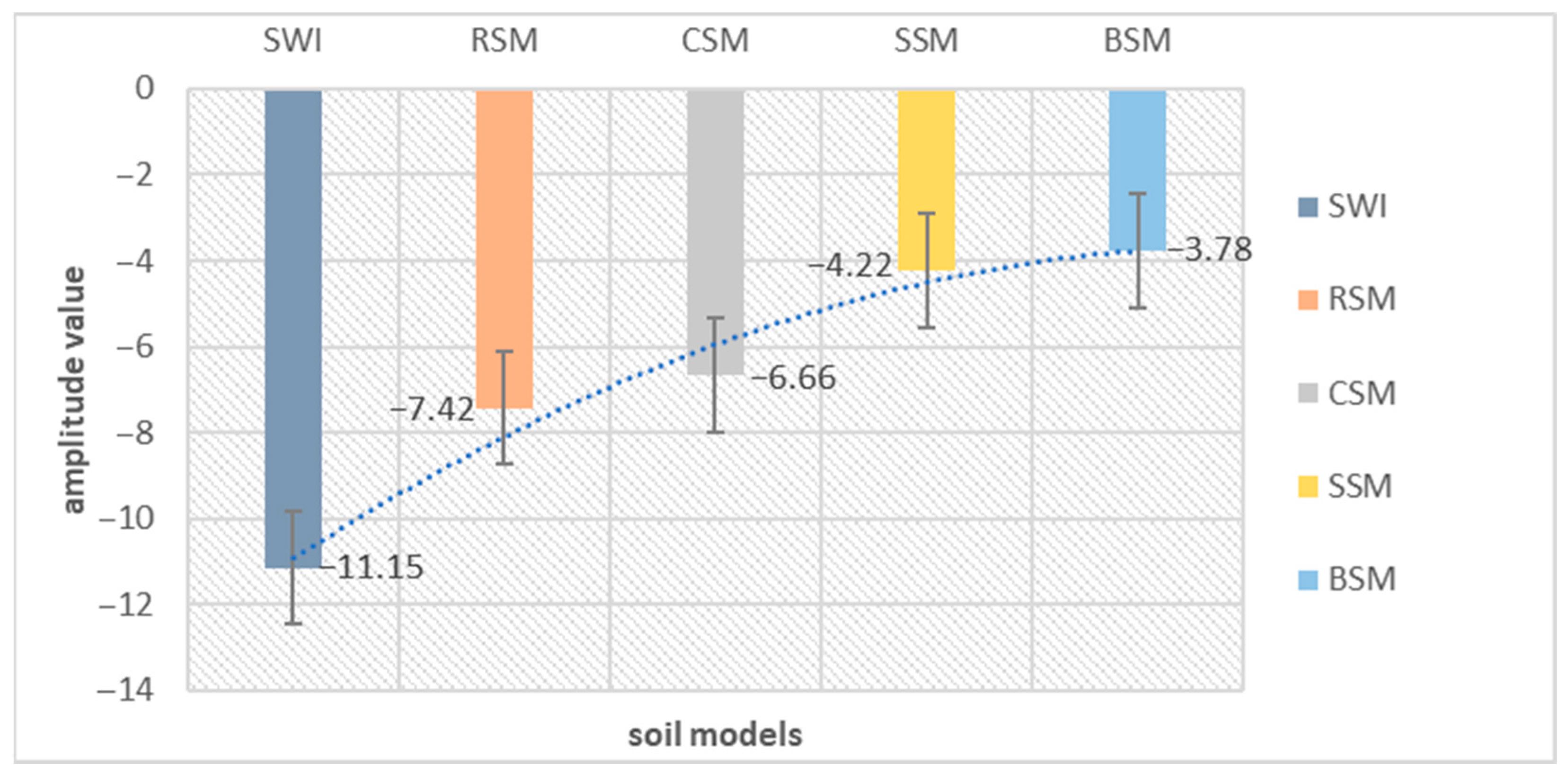
| Parameters | Soil without Impurities | Soil–Cement | Soil–Bitumen | Silicate Soil | Soil–Rubber |
|---|---|---|---|---|---|
| Minimum amplitude value | −11.152 | −6.6625 | −3.78249 | −4.22825 | −7.42375 |
| Maximum amplitude value | 6.85825 | 2.15185 | 1.40175 | 2.804 | 2.477875 |
| Mathematical expectation | −0.42675 | 0.009475 | 0.233575 | −0.10678 | 0.1355 |
| Mean square value | 1.864 | 0.366 | 0.469875 | 0.29925 | 0.651 |
| Average square deviation | 1.807 | 0.36075 | 0.3975 | 0.27925 | 0.63575 |
| Main frequency | 0.00085 | 0.00225 | 0.000825 | 0.0875 | 0.02975 |
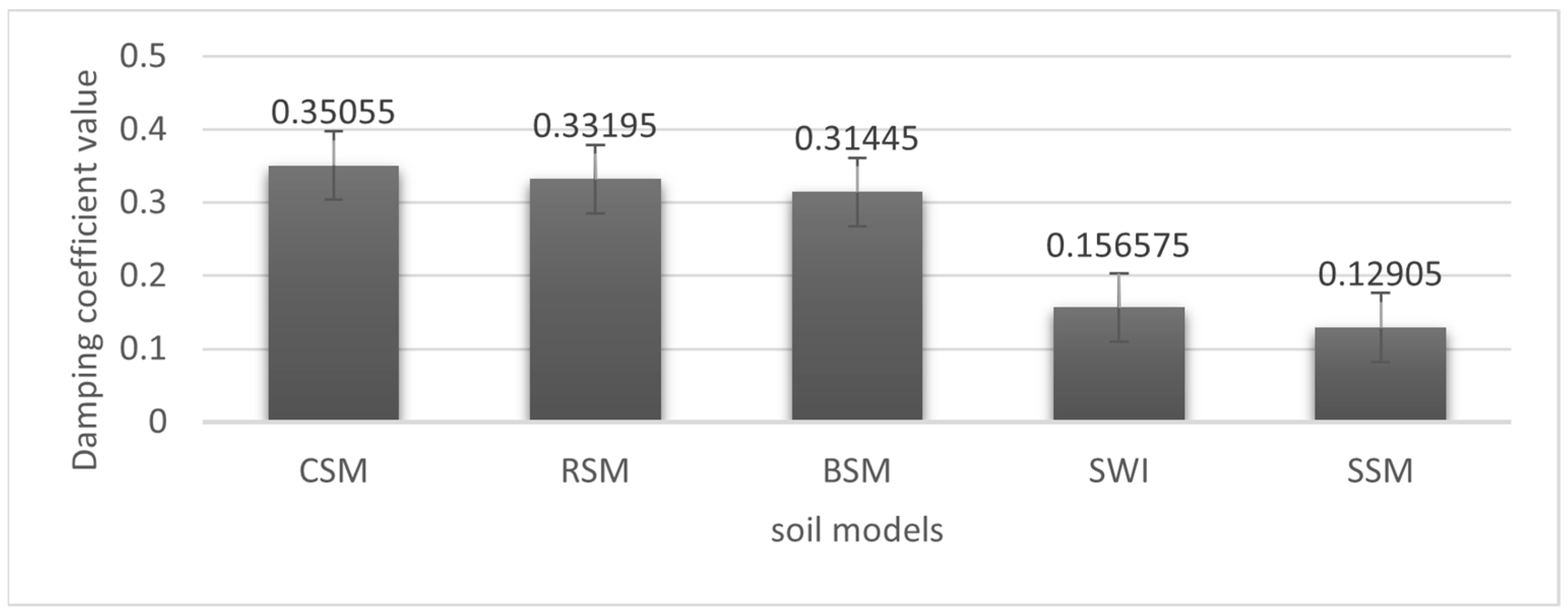
| Soil Model Name | Damping Coefficient | |||
|---|---|---|---|---|
| Experiment 1 | Experiment 2 | Experiment 3 | Experiment 4 | |
| Soil without impurities (SWI) | 0.2526 | 0.0755 | 0.1763 | 0.1219 |
| Cement–soil mixture (CSN) | 0.3306 | 0.3655 | 0.4864 | 0.2197 |
| Bitumen–soil mixture (BSM) | 0.4687 | 0.3079 | 0.2532 | 0.228 |
| Silicate soil mixture (SSM) | 0.1249 | 0.1194 | 0.1353 | 0.1366 |
| Rubber–soil mixture (RSM) | 0.2538 | 0.427 | 0.313 | 0.334 |
Disclaimer/Publisher’s Note: The statements, opinions and data contained in all publications are solely those of the individual author(s) and contributor(s) and not of MDPI and/or the editor(s). MDPI and/or the editor(s) disclaim responsibility for any injury to people or property resulting from any ideas, methods, instructions or products referred to in the content. |
© 2024 by the authors. Licensee MDPI, Basel, Switzerland. This article is an open access article distributed under the terms and conditions of the Creative Commons Attribution (CC BY) license (https://creativecommons.org/licenses/by/4.0/).
Share and Cite
Bessimbayev, Y.T.; Niyetbay, S.E.; Awwad, T.; Kuldeyev, E.I.; Uderbayev, S.S.; Zhumadilova, Z.O.; Zhambakina, Z.M. The Creation of Geotechnical Seismic Isolation from Materials with Damping Properties for the Protection of Architectural Monuments. Buildings 2024, 14, 1572. https://doi.org/10.3390/buildings14061572
Bessimbayev YT, Niyetbay SE, Awwad T, Kuldeyev EI, Uderbayev SS, Zhumadilova ZO, Zhambakina ZM. The Creation of Geotechnical Seismic Isolation from Materials with Damping Properties for the Protection of Architectural Monuments. Buildings. 2024; 14(6):1572. https://doi.org/10.3390/buildings14061572
Chicago/Turabian StyleBessimbayev, Yerik T., Sayat E. Niyetbay, Talal Awwad, Erzhan I. Kuldeyev, Saken S. Uderbayev, Zhanar O. Zhumadilova, and Zauresh M. Zhambakina. 2024. "The Creation of Geotechnical Seismic Isolation from Materials with Damping Properties for the Protection of Architectural Monuments" Buildings 14, no. 6: 1572. https://doi.org/10.3390/buildings14061572
APA StyleBessimbayev, Y. T., Niyetbay, S. E., Awwad, T., Kuldeyev, E. I., Uderbayev, S. S., Zhumadilova, Z. O., & Zhambakina, Z. M. (2024). The Creation of Geotechnical Seismic Isolation from Materials with Damping Properties for the Protection of Architectural Monuments. Buildings, 14(6), 1572. https://doi.org/10.3390/buildings14061572