Article

Shear Performance and Damage Characterization of Prefabricated Basalt Fiber Reactive Powder Concrete Capping Beam Formwork Structure

1
College of Transportation, Jilin University, Changchun 130025, China
2
Longjian Road and Bridge Company Limited, Harbin 150009, China
3
China Railway Ninth Bureau Group No. 1 Construction Co., Ltd., Suzhou 215538, China
4
Engineering Co., Ltd., CCCC Second Highway Engineering, Xi’an 710000, China
*
Author to whom correspondence should be addressed.
Buildings 2024, 14(6), 1701; https://doi.org/10.3390/buildings14061701
Submission received: 10 May 2024 / Revised: 29 May 2024 / Accepted: 4 June 2024 / Published: 7 June 2024
(This article belongs to the Special Issue Recent Research Progress of UHPC in Structural Engineering)

Abstract

:
Basalt Fiber Reactive Powder Concrete (BFRPC) semi-prefabricated composite capping beam structures can effectively improve the shortcomings of ordinary concrete capping beams' construction difficulties and insufficient bearing capacity. In this study, with the objective of analyzing the shear damage and damage characteristics of a prefabricated BFRPC capping beam formwork, structural damage tests under different levels of loading were carried out to obtain the mechanical parameters of key nodes. Acoustic emission (AE) and Digital Image Correlation (DIC) techniques were used to acoustically and visually characterize the formwork damage. The research results showed that the damage stage of the capping beam formwork was divided, and an early damage warning method was proposed based on the acoustic parameters. Using the DIC technique to identify the crack width evolution pattern during the shear process, it was found that the cracks expanded steadily as the load increased. Combining the experimental and simulation results as well as the Subdivision Superposition Theory, a half-open stirrup strength discount factor β was introduced and suggested to take a value of 0.79. The formula for calculating the shear capacity of BFRPC capping beam formwork is proposed to provide a theoretical basis for its application in prefabricated assembled structures.

1. Introduction

In recent decades, accelerated bridge construction has become increasingly popular worldwide. In the context of today’s greening upgrade and transformation of the construction industry, how to support the upgrade and transformation of the construction of traditional infrastructure to be energy-saving, environmentally friendly, fast, safe, efficient, and aesthetically pleasing has become a new requirement of the times [1]. As an important structure in bridge engineering, the role of the capping beam is to transfer the loads on the bridge deck to the substructure [2]. However, there are still challenges in the construction of capping beam structures that have not been resolved. On the one hand, the self-weight of the capping beam can reach 200–400 t, which leads to the disadvantages of high requirements for lifting equipment, high transportation costs, and installation difficulties [3]. On the other hand, the integral cast-in-situ construction method will affect the traffic and extend the construction period, which is not in line with the concept of fast and efficient construction [4,5]. In addition, ordinary concrete capping beams are prone to cracking, poor durability, and other shortcomings. The service life of the capping beams is significantly shortened under the influence of freezing and thawing environments [6,7,8]. Therefore, the new semi-prefabricated permanent capping beam formwork structure, which requires little lifting equipment, no formwork casting, and a simple construction process, will increasingly become the center of gravity in the design of capping beam engineering. Semi-prefabricated capping beam formwork structure technology prefabricates the shell components of the capping beam in the factory and casts the concrete inside after transportation to the construction site [9]. The Dubai Railway Viaduct in the UAE divides the thin-walled concrete capping beam formwork into segments, which are assembled and completed on site before the core concrete is poured. Chung [10] in South Korea proposed a new semi-prefabricated T-shaped capping beam system consisting of a prefabricated capping beam shell and post-cast concrete. The test results showed that there was little difference between the yield capacity and bearing capacity of the composite structure and the traditional structure, but the ductility of the composite structure was better than that of the traditional structure [11,12,13,14].
With the advent of high-performance composites such as ultra high-performance concrete (UHPC), the formwork of semi-prefabricated composite structures has also applied these new materials. Lin Yang and Wu Xiangguo et al. [15,16,17] studied the flexural and shear performance of UHPC-NC (normal concrete) semi-prefabricated composite beams and found that the failure mode was similar to that of conventional structures, and the ultimate load that semi-prefabricated beams can withstand was greater than that of cast-in-place beams. Increasing the UHPC thickness resulted in a downward shift in the area of initial cracking of the laminated beams [18]. In addition, composite concrete beams made of UHPC shells have higher torsional properties than ordinary RC beams [19,20,21]. Zhang Rui et al. found that a U-shaped ECC formwork enabled the ultimate load and ductility of the monolithic beams to be improved, and established a prediction equation for the shear capacity of ECC-RC stacked beams [22]. Xinying Wang [23] conducted flexural and shear tests on a prefabricated U-shaped RPC permanent beam formwork as well as laminated beams. It was found that increasing the thickness of the baseplate can increase the flexural capacity of the formwork, and increasing the thickness of the sidewalls can increase the shear capacity, and a method for calculating the shear capacity was proposed. In summary, it was found that the failure process of stacked structures differed less from that of cast-in-place structures provided that the interfaces of the composite structures were well bonded [24]. However, most of the theoretical analyses of the tests mentioned above were for the frame girder form, with fewer studies involving the capping beams.
Yun, H. found that the performance of steel fiber-reinforced concrete containing high strength steel fibers was better than that of steel fiber-reinforced concrete containing ordinary strength steel fibers [25]. Yang Xin’s and Dong Hong’s studies found that the incorporation of polypropylene fibers into concrete beams increased the initial crack shear force of the beam, increased the number of cracks, and reduced the crack width, thereby improving the ductility of the beam and inhibiting the formation of cracks [26,27]. Steel fibers and polypropylene fibers, which are commonly used in UHPC, can effectively improve concrete performance and structural load-bearing capacity. At the same time, there are problems such as poor corrosion resistance and environmentally unfriendly production processes [28,29].
Basalt Fiber Reactive Powder Concrete (BFRPC), as a kind of ultra high-performance concrete (UHPC), is a new type of green, energy-saving and environmentally friendly material with a higher strength as well as higher durability than normal concrete materials [30]. However, the research on the design, construction, and acceptance of infrastructure structures using this material as a mainstay is in its infancy. In this study, BFRPC was applied as the formwork material for semi-prefabricated capping beams to achieve the goal of reducing the weight of prefabricated formworks and improving the load-carrying capacity and durability of the overall capping beam structure [31,32,33].
In order to solve the problem of the loss of bearing capacity due to the influence of concentrated stress during the lifting, transportation, and construction phases of capping beam formwork structures, this paper presents the shear capacity test of a prefabricated capping beams formwork. The acoustic emission and DIC techniques were used to characterize the damage process of the capping beam formwork from acoustic and visual perspectives. A shear capacity calculation model for BFRPC capping beam formworks based on the Subdivision Superposition Theory was established, which can effectively predict the ultimate shear capacity of BFRPC as a semi-prefabricated capping beam formwork, and put forward reasonable suggestions for structural designs. The prefabricated BFRPC capping beam formwork proposed in this study can improve the service performance and service life of the capping beam, reduce the huge economic losses caused by the destruction and reconstruction of transportation infrastructure, and provide theoretical references for the design and rapid construction of cantilever beam structures in urban bridge construction.

2. Materials and Experimental Program

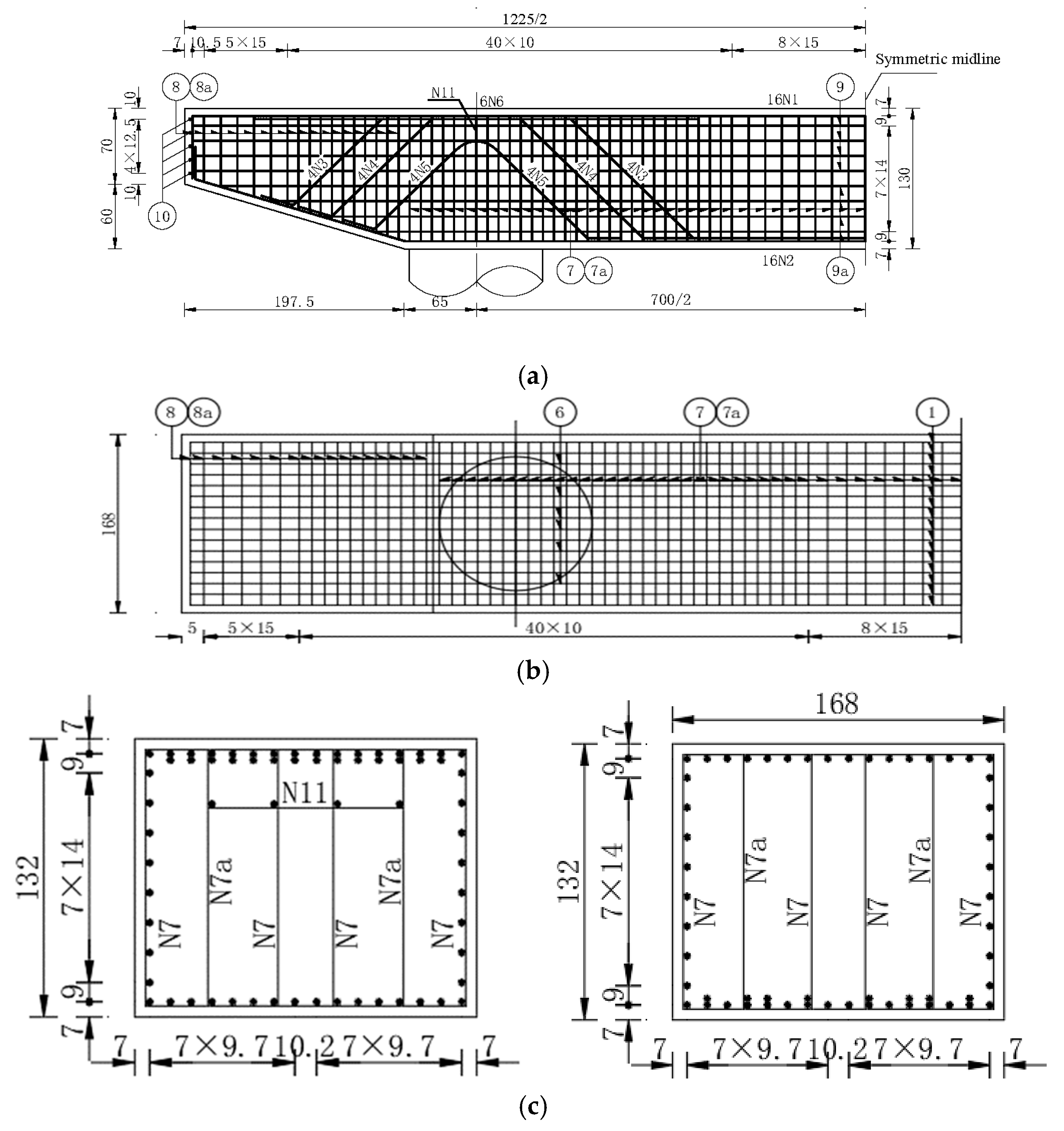
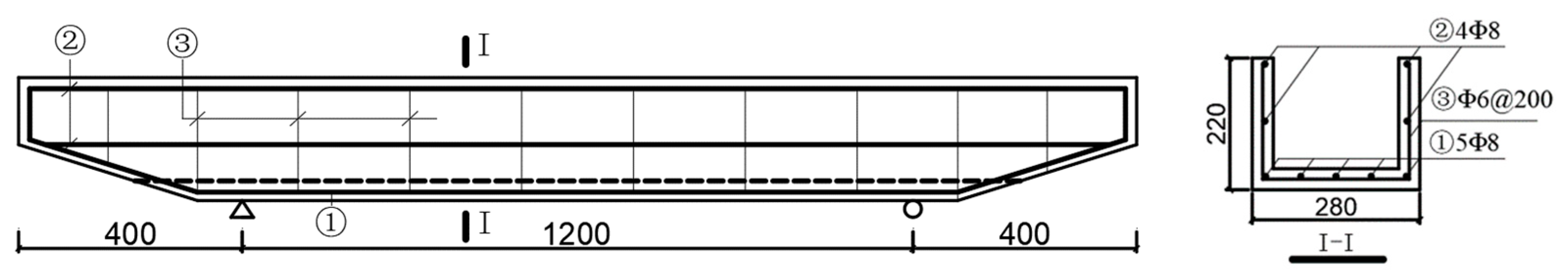
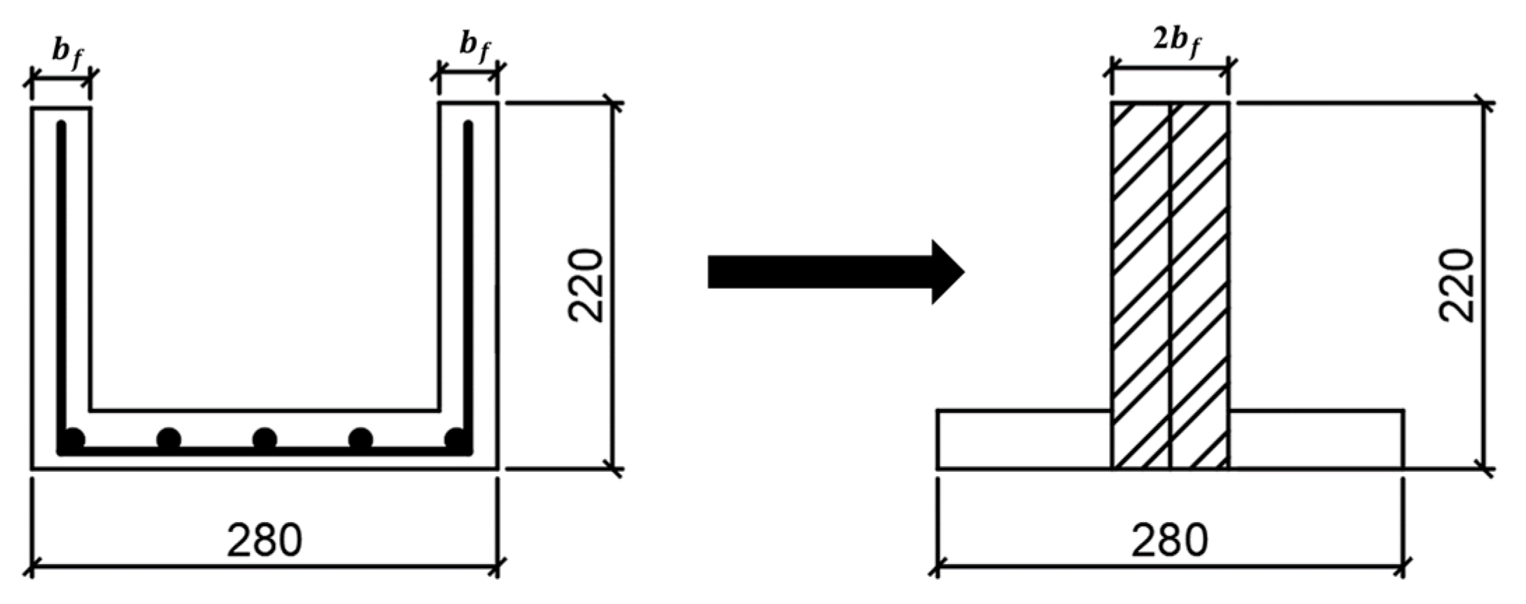
2.1. Design of Test Formwork Dimensions
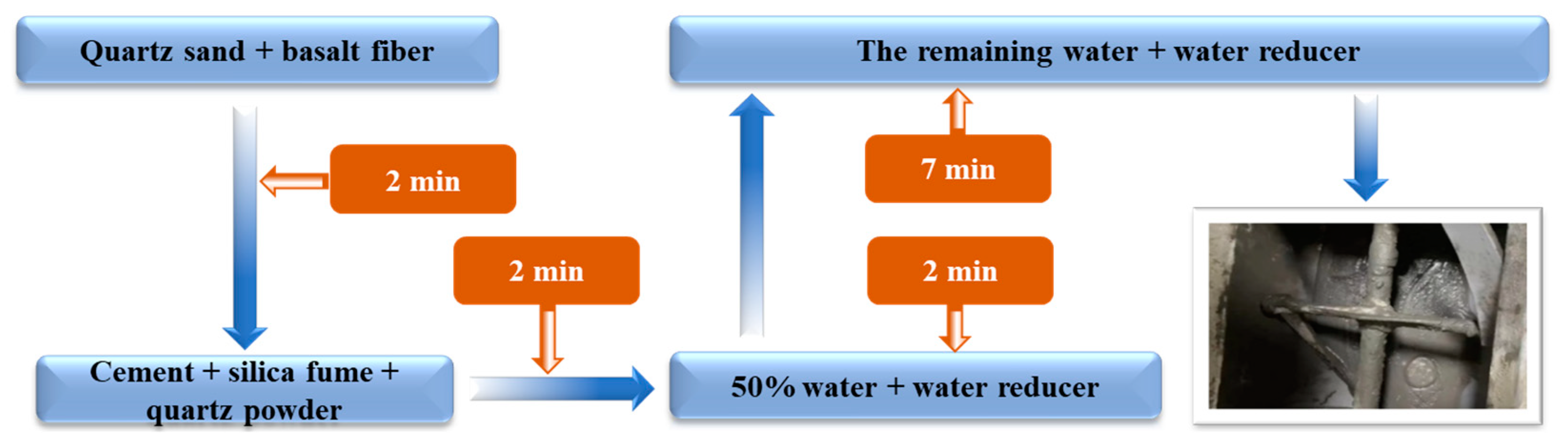
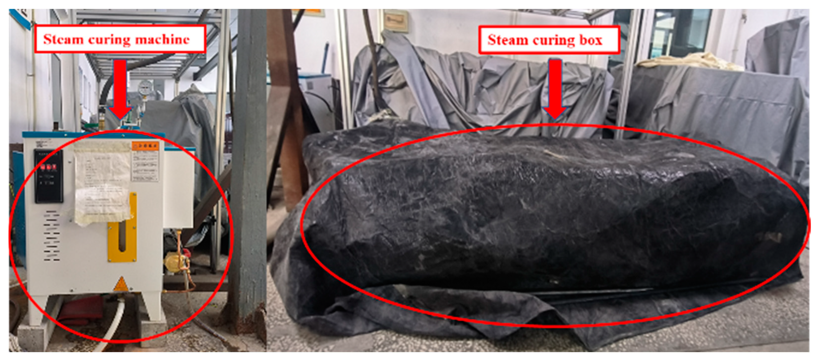
According to the actual structure in the project, the capping beam formwork was scaled down using a similarity ratio of 1:6. Based on the principle of using the same reinforcement rate for its reinforcement design, the reinforcement rate of the formwork was 1.28%. The specific parameters of the test beams and the parameter similarity ratio are shown in Table 1. The actual capping beam dimensions are shown in Figure 1, and the structural dimensions are shown in Figure 2.

2.2. Materials

Combined with the findings of previous experiments [32], the performance of BFRPC was found to be optimal when the water–cement ratio was 0.18, and the BFRPC compatibility ratio used in this study is shown in Table 2. The mixing process was carried out in accordance with the Standard for Test Method of Performance on Ordinary Fresh Concrete [34] (GB/T 50080-2016), as shown in Figure 3.
The molds of the capping beam formwork were made of recyclable and removable steel plates. The outer and inner molds of the BFRPC formwork were fixed with screws at multiple points to ensure the accuracy of the thickness of the formwork, as shown in Figure 4.
Considering the design size, style, and test conditions of the BFRPC formwork, the method of pouring the base plate first, carrying out the bolting of the inner mold, and then continuing to pour the side plate was adopted. During the pouring process, the formwork was vibrated with a vibrating rod to ensure its compactness, and the finished formwork is shown in Figure 5. High-temperature heat treatment curing can improve the microstructure of BFRPC and improve the performance of BFRPC, and according to the requirements of the Fundamental Characteristics and Test Methods of Ultra High-Performance Concrete standard (T/CCPA 7-2018) [35], it is necessary to carry out steam curing of BFRPC materials. As shown in Figure 6, the steam curing was performed with a curing temperature of 90 °C for 48 h. The natural curing for 7 d was performed while keeping the surface of the BFRPC moist after steam curing.

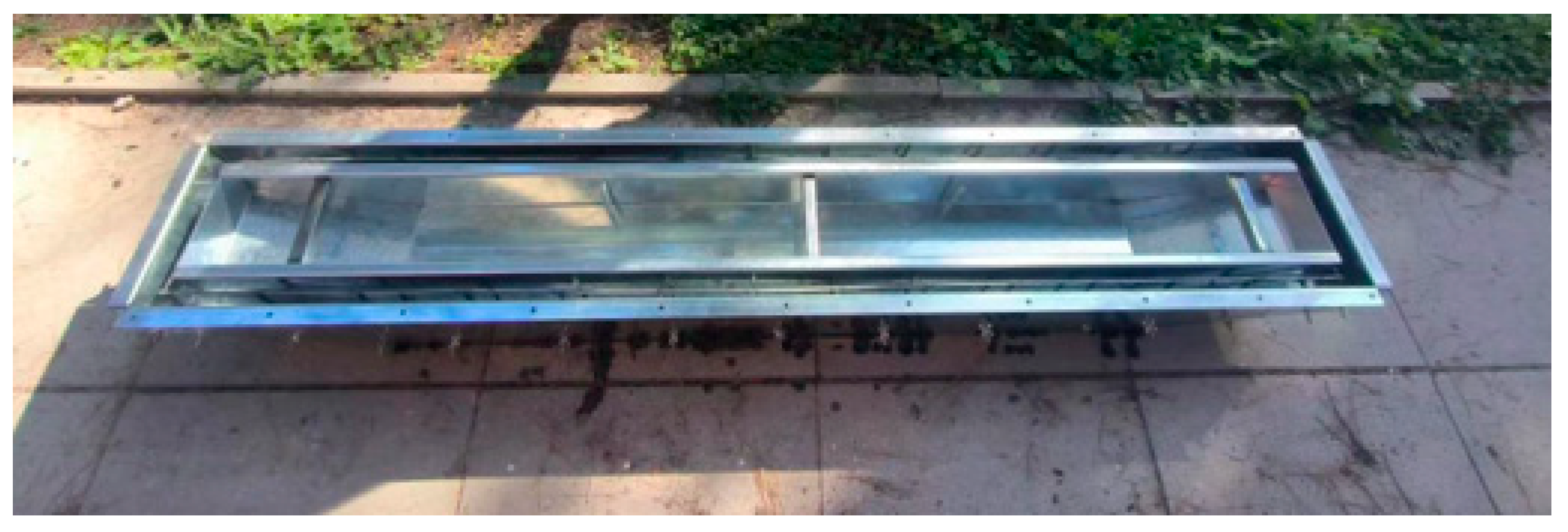
2.3. Structural Test

The BFRPC capping beam formwork shear test loading device was a 100-ton electro-hydraulic servo member dynamic and static testing machine produced by Changchun New Testing Machine Factory, and the steel bar in the span of the centralized force loading was used. The test loading scheme and instrumentation layout is shown in Figure 7, and the field loading diagram is shown in Figure 8. According to the Standard for Test Method of Concrete Structures (GB/T 50152-2012) [36], the BFRPC capping beam formwork was preloaded at a loading rate of 0.1 kN/s before the start of the test loading, followed by graded loading using a load of 3 kN per stage. The load was maintained for 3 min at each stage and the data were collected. The SAEU2S-6 acoustic emission acquisition and analysis system produced by Beijing Shenghua Xingye Technology Co., Ltd. was used for acoustic signal acquisition. Acoustic emission probes were placed at the center of each side of the curved shear section to collect acoustic signals during the damage process. The DIC collection equipment was produced by Beijing Long Time Yuan Yang Technology Co., Ltd. A CCD camera was used to capture the BFRPC capping beam formwork morphology during the full time frame of loading. The test setup is shown in Figure 9.

3. Results

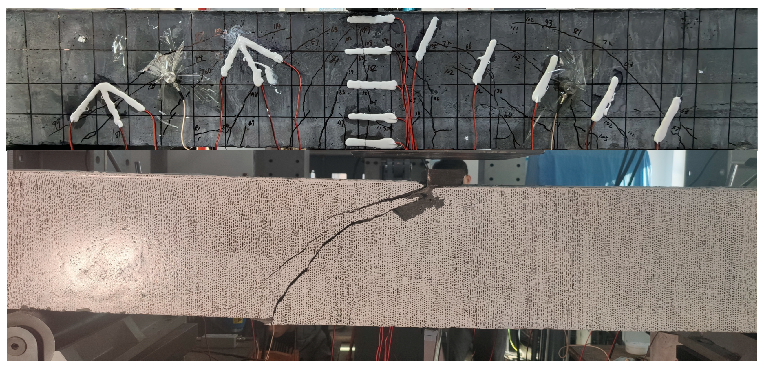
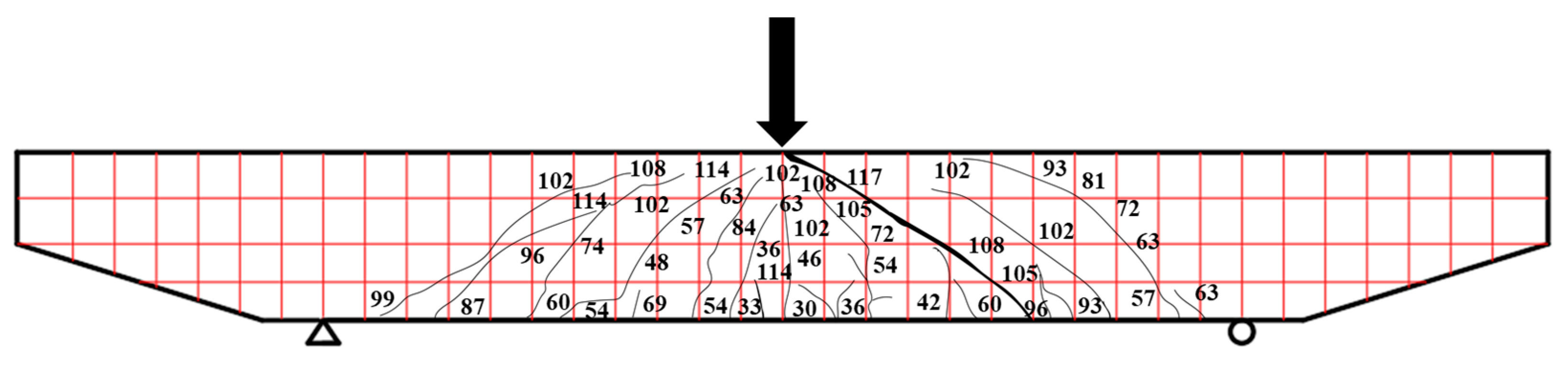
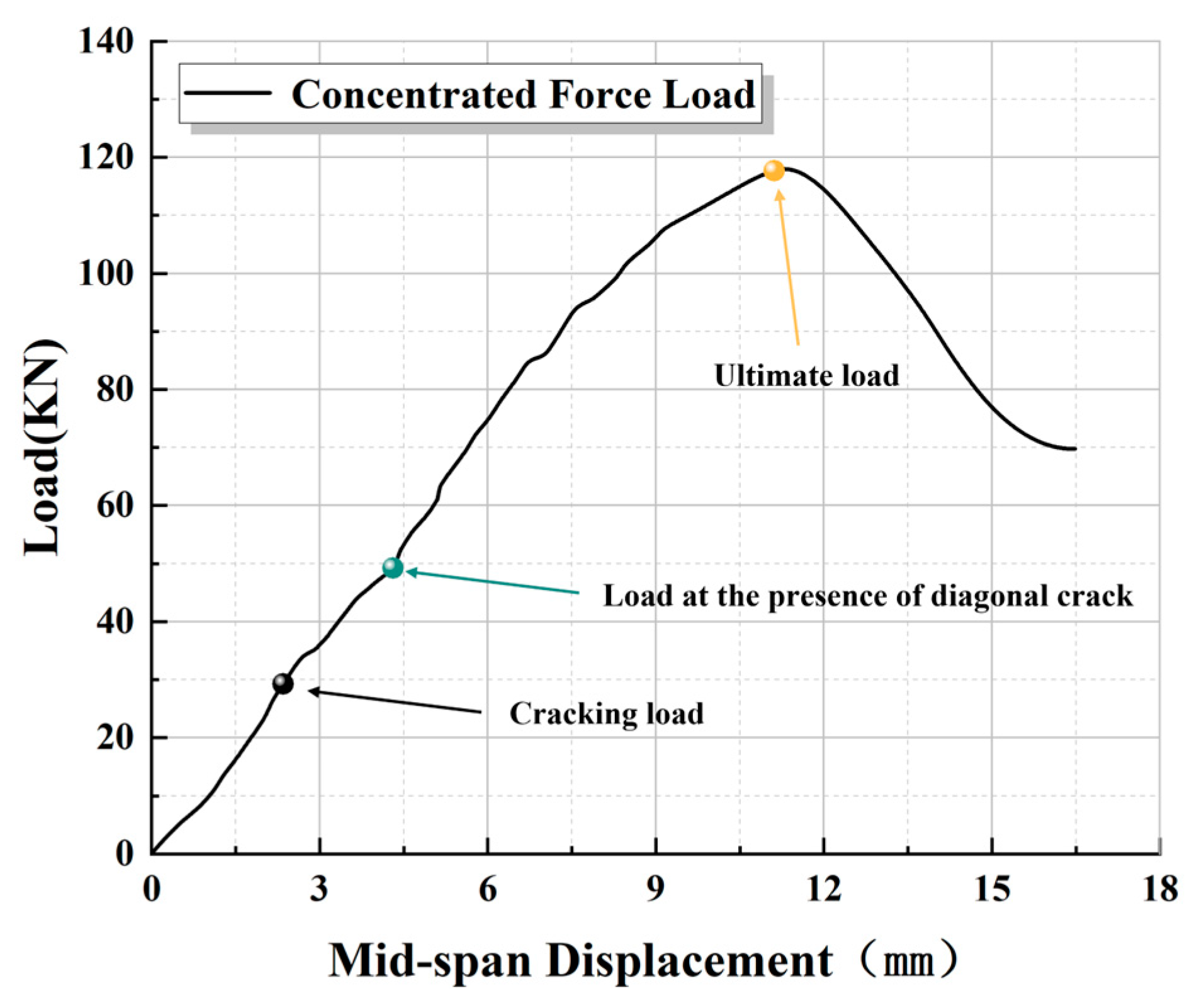
3.1. Shear Failure Mode of Prefabricated BFRPC Capping Beam Formwork

The peak load in the three-point loading test directly reflects the shear load capacity of the BFRPC formwork. The failure mode of the capping beam formwork after damage is shown in Figure 10, while Figure 11 reflects the crack development during the loading of the capping beam formwork The load displacement data are shown in Table 3. Based on the test data, the load–displacement curves were plotted. At the beginning of loading, the formwork was in a complete stress state and the load displacement curve rose uniformly [37].
As shown in Figure 12 and Table 3, when loaded to 30 kN, the first bending crack was produced in the bottom region of the span of the formwork and the width was less than 0.05 mm. At this time, the slope of the curve began to change. When loaded to 48 kN, the first diagonal crack appeared on the side wall of the formwork along the direction of the loading point. At the same time, the bending cracks also began to expand laterally along the direction of the loading point. As the load increased, an increasing number of parallel diagonal cracks began to be generated. When loaded to 60 kN, transverse cracks extending to the interior of the bottom of the formwork side wall appeared continuously, indicating that the side wall was subjected to a large load at this time, which gradually developed to a state of instability. When finally loaded to 117 kN, the formwork reached the state of ultimate load capacity, and the mid-span displacement changed rapidly. A diagonal crack on one side of the BFRPC formwork, starting from the bottom and expanding in the direction of the loading point, became a critical crack and eventually destabilized. The concrete in the shear compression zone underwent damage under different stresses. The final crack width was more than 4.5 mm, and the whole formwork underwent shear pressure damage.

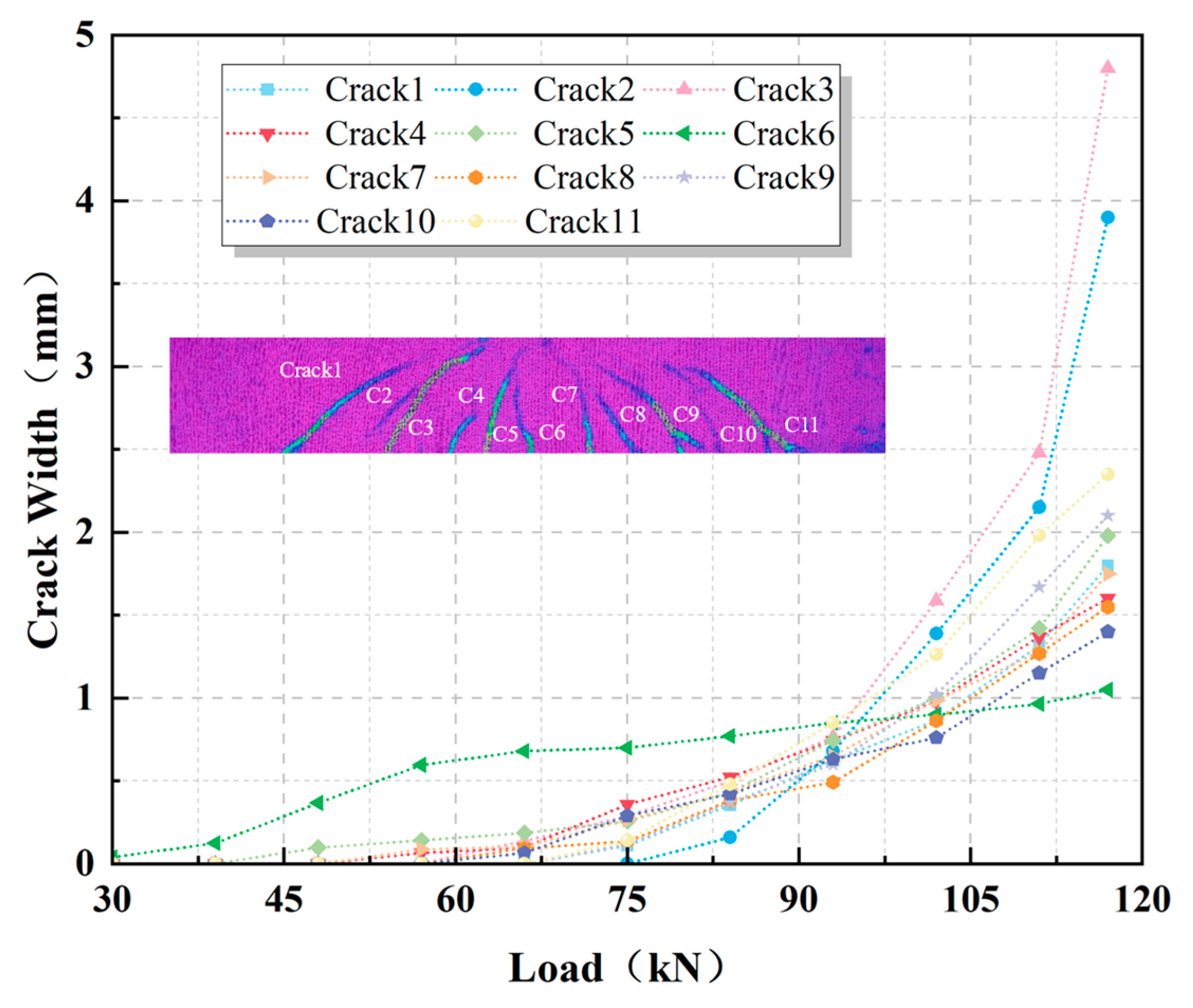
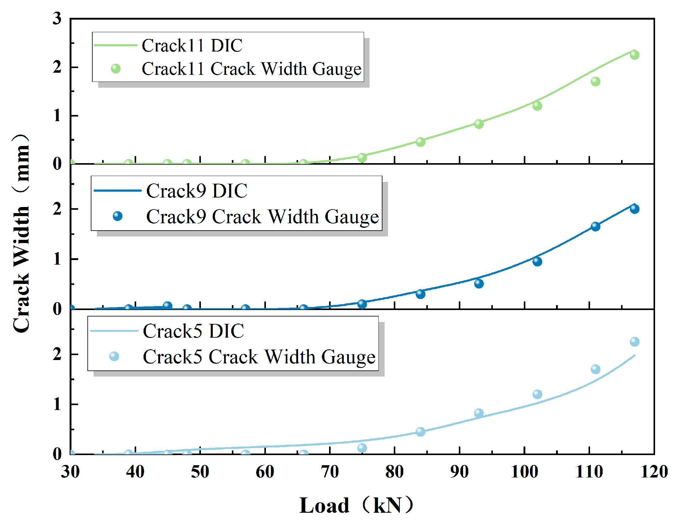
3.2. Evolution of Cracks during Shear Damage

Information on the development of cracks is shown in Figure 13; the comparison shows that all the bending cracks had a similar trend to that of the diagonal cracks. The number of cracks did not increase during the expansion phase. However, the width of the existing main crack gradually increased, and finally a diagonal crack with a large width was transformed into a critical crack and damaged under the ultimate load, which was consistent with the test phenomenon.
The crack width was calculated indirectly using DIC analysis software (License MatchlD), and combined with the test data, the evolution law of the crack width under different load levels was investigated. The crack information at different load levels is shown in Figure 13. It can be found through a comparison that all the bending cracks and diagonal cracks (Crack 1–Crack 11) continued to expand steadily with increasing load. A phase of continuous crack expansion occurred in the later stages of loading when the number of cracks no longer increased, but the width of the existing main cracks (Crack 2 and Crack 3) gradually increased. With the increase in load, the force that the diagonal crack (Crack 3) section with the largest width can withstand decreases and gradually transforms into a critical crack. Instability damage occurred when the ultimate load was reached, which is consistent with the test phenomenon.
The three main cracks of the selected formwork were plotted against the different data presented by the DIC and the crack width gauge, as shown in Figure 14. It can still be found that the crack width errors presented by the two methods were small, which further validates the reliability of the practical application of DIC in crack width measurements.

3.3. Acoustic Characterization of Shear Damage in BFRPC Capping Beam Formwork

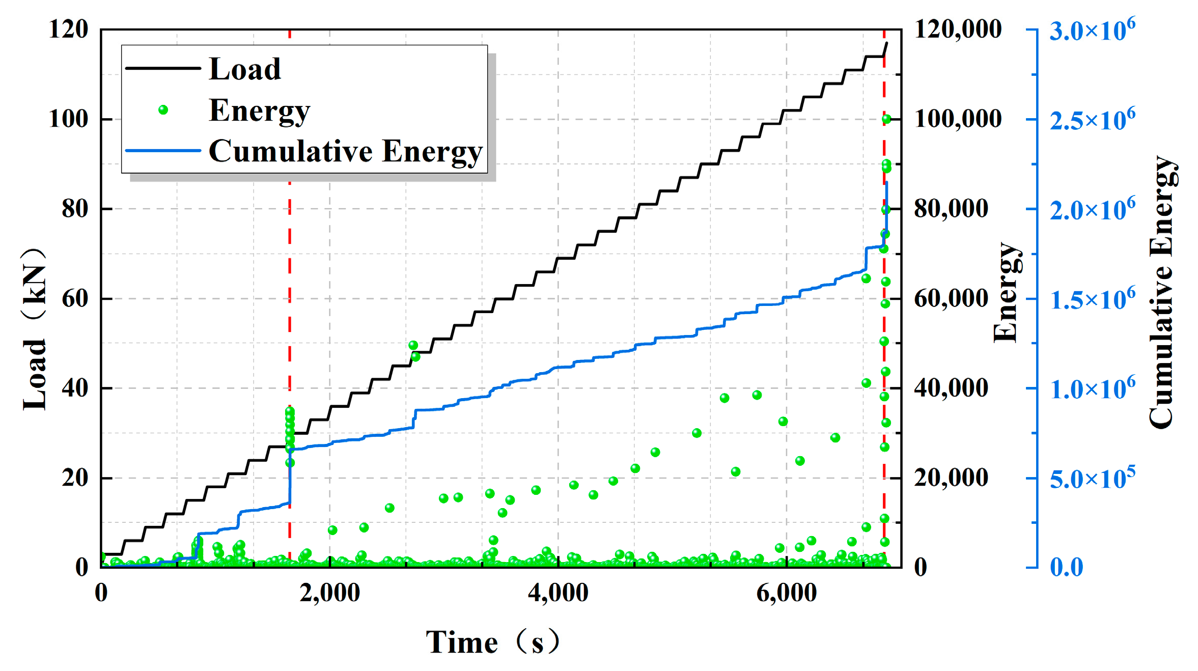
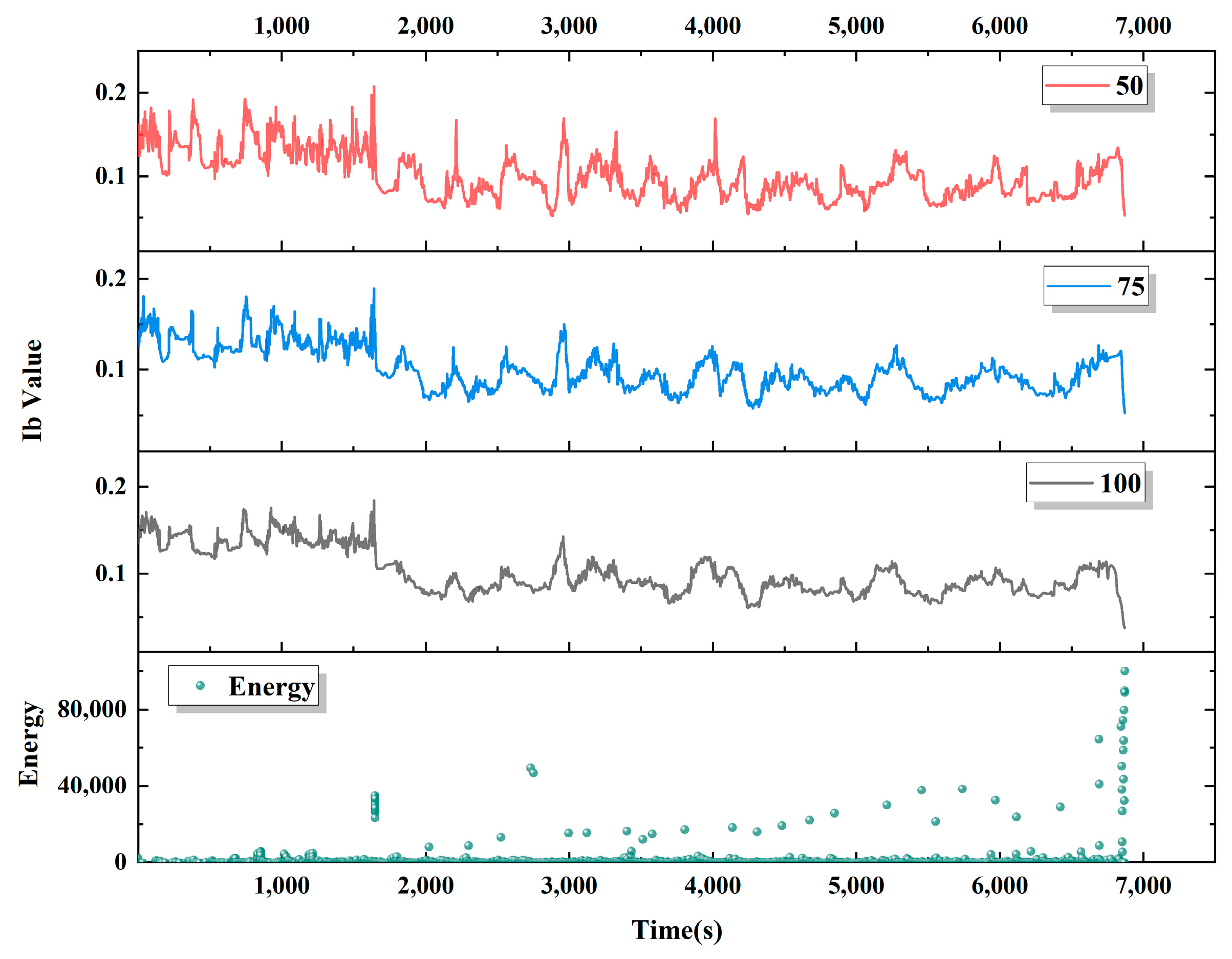
3.3.1. Energy Analysis

Figure 15 shows the curves of acoustic emission energy versus time during the whole process of the three-point concentrated loading test of the BFRPC capping beam formwork. Figure 16 shows the acoustic emission cumulative energy time course curve. Through the test phenomenon, the whole process of the three-point centralized loading test can be divided into three stages: Stage I (crack initiation stage), Stage II (crack extension stage), and Stage III (destruction stage).
① The crack initiation stage occurred in the 0 s–1650 s period. Within this phase, the acoustic emission energy level was low. A few of the energy jump points were due to friction between the voids inside the BFRPC formwork, resulting in acoustic emission signal generation. As the loading continued, the first peak was reached at around 1650 s. This was the first time a flexural crack appears, and the cumulative energy curve showed a sudden change in slope at this point.
② Crack extension stage occurred in the 1650 s–6690 s period. After the appearance of flexural cracks, the cracks entered a stable stage of development. At around 2650 s, the first diagonal cracks started to develop in the formwork. At this point the energy release gradually increased and the cumulative energy curve showed a second point of change in slope. The acoustic emission activity was at a high level during this phase.
③ Destruction stage occurred in the 6690 s–6870 s period. Within this phase, the formwork entered the destabilizing and destructive phase. The cracks continued to widen in width along with the crackling sound of basalt fibers being pulled out from inside the formwork. The energy release reached its maximum value at about 6870 s when the load-bearing capacity of the formwork reached its limit and shear–compression damage eventually occurred.

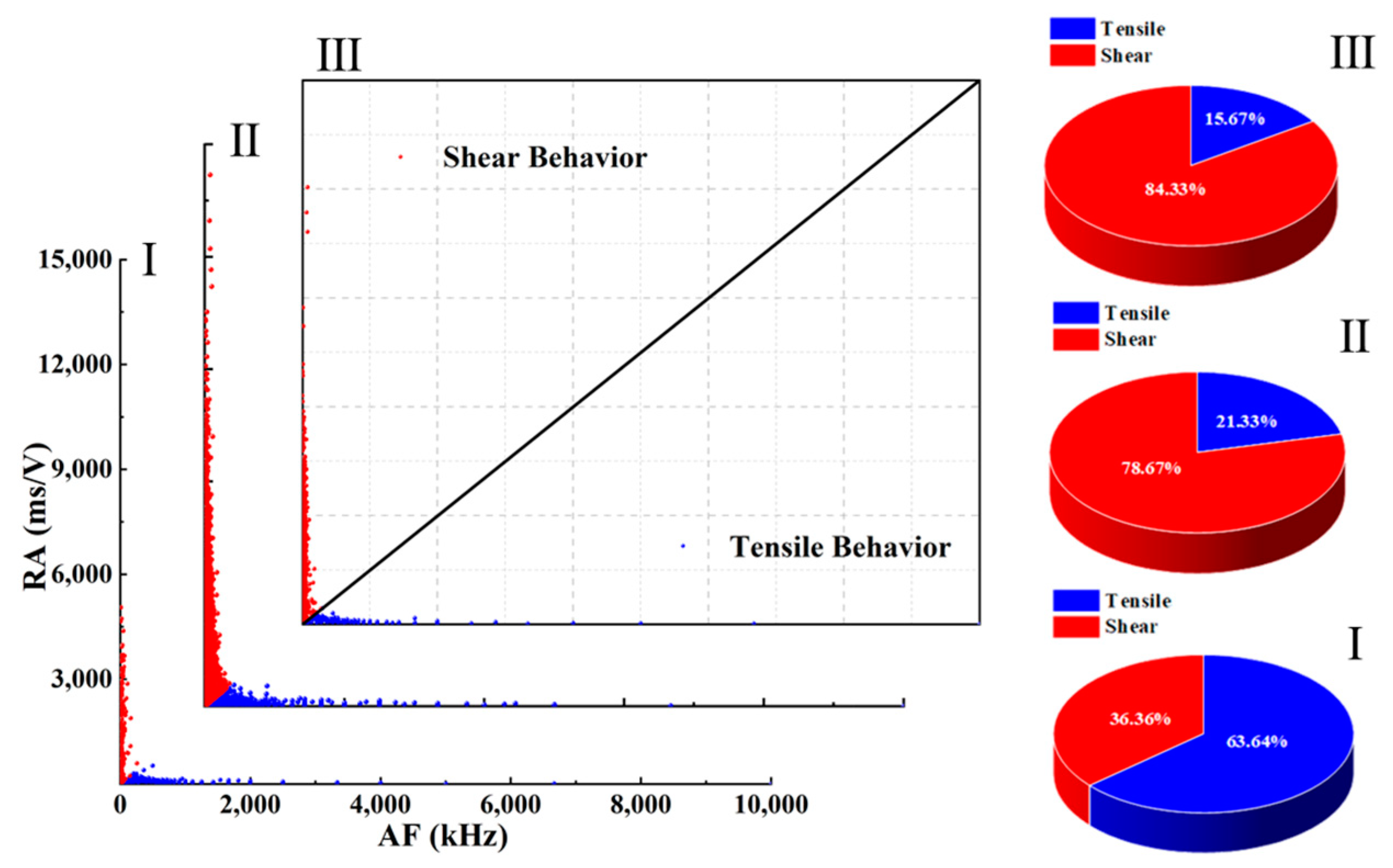
3.3.2. RA-AF Correlation Analysis

Figure 17 represents the scatter plot of acoustic emission RA-AF at each stress level stage in the three-point concentrated loading test of the capping beam formwork corresponds to the three stages in Section 3.3.1. Figure 18 represents the scatter plot of acoustic emission RA-AF over the whole course of the experiment. It can be found that when the time was less than 1650 s, the scatter was mostly distributed on the side of the axis where the AF value is located, accounting for about 63.6% of the time. The above phenomenon indicates that the process was in the crack initiation stage, when the tensile mode was dominant. At 1650 s–6690 s, the scatter became larger on the side of the axis where the RA value is located. This means that both shear and tensile modes existed in this process, and the RA value was larger than the AF value, which means that the shear mode was dominant in this stage. The percentage of RA values continued to increase after 6690 s, indicating that the process destroyed the dominance of the shear mode.

3.3.3. Ib Value Analysis

Different group sizes (50, 75, and 100) were selected to calculate the Ib values and the acoustic emission Ib values were plotted versus time as shown in Figure 19. In Stage I, the Ib value was large and fluctuated rapidly, indicating that a large number of microcracks sprouted at the interface of the BFRPC formwork. In Stage II, the Ib value began to show a decreasing trend, and the fluctuation was still large, which indicates that both internal microcracks and surface macrocracks in the formwork were sprouting and expanding in this process. After 6690 s, the Ib values showed a decreasing trend and no significant fluctuations, indicating that the microscopic cracks rapidly developed into macroscopic cracks. Wider macro cracks will continue to undergo instability expansion and eventually evolve into damage. A significant decrease in the Ib value can serve as an early warning of damage to the BFRPC formwork structure.

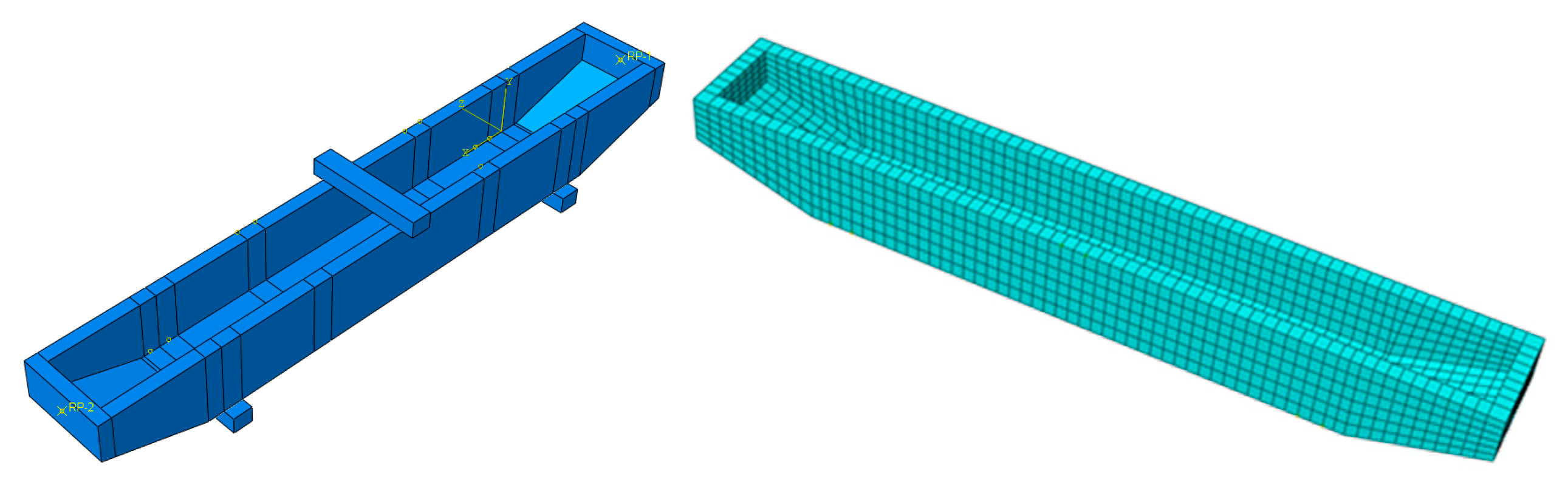
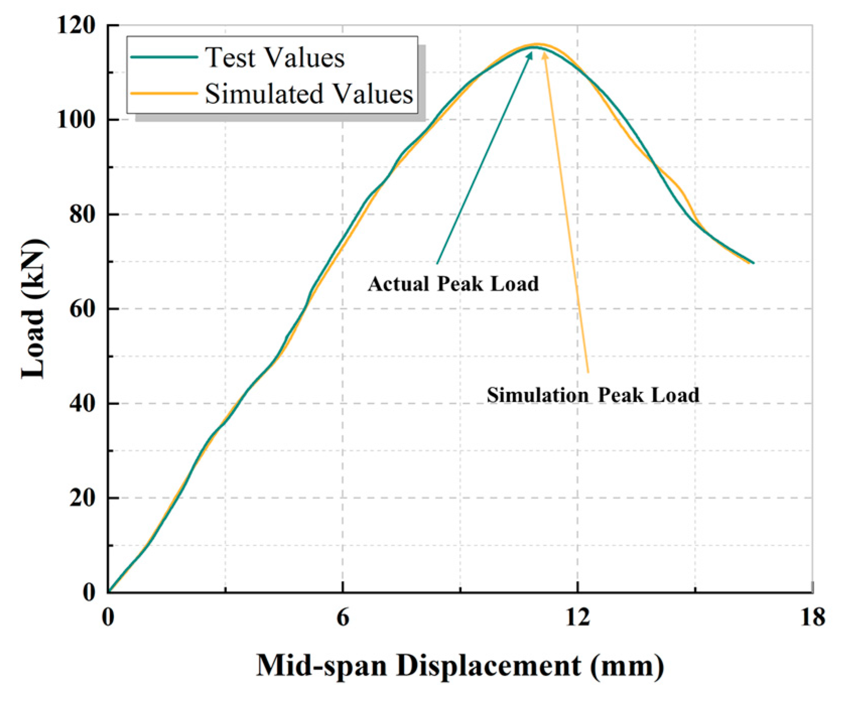
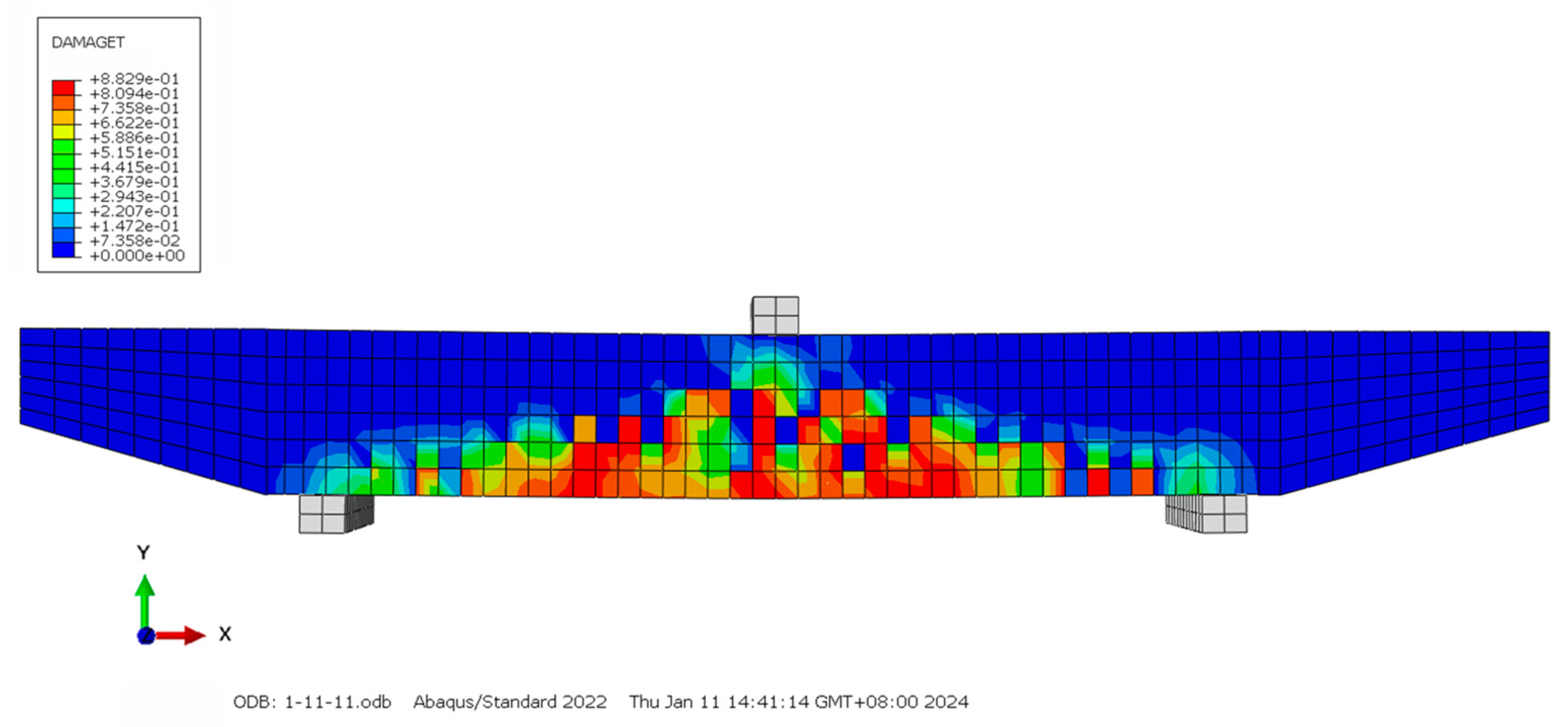
3.4. Numerical Simulation Analysis of BFRPC Capping Beam Formwork

The FE modeling method can effectively simulate the compressive damage to BFRPC capping beam formworks [38,39]. Tensile and compressive principal relationships of BFRPC were derived using uniaxial compression tests on the concrete and its FE solid model was established according to the corresponding modeling parameters and formwork dimensions, as shown in Figure 20.
Using the uniaxial compression test, the BFRPC compression stress–strain constitutive relationship equation was obtained, as shown in Equation (1). The equation for the stress–strain principal relationship under compression is shown in Equation (2).
y = x + x 5 x 6                                                             0 x 1 x 3 x 1 2 + x                                                                           x > 1
y = 2.088 x                                                                   0 x 0.4789       1                                                                       0.4789 x 1 x 3.2 x 1 1.43 + x                                                                   x > 1
The mesh was divided by the method of “first coarse and then fine”. The mesh spacing was reduced until the results of the two simulations were within the allowable computational difference, while keeping the stress and displacement trends constant as the basis for meshing. A swept grid with 30 mm spacing was used depending on the span and thickness of the capping beam formwork.
The mid-span displacement versus load curve of the FE model was output as shown in Figure 21. The damage pattern of the capping beam girder model was calculated according to the BFRPC plastic damage model, as shown in Figure 22. The numerical calculations were consistent with the force conditions of the test formwork. Based on the structural test of the BFRPC capping beam formwork, the FE model was used to change the reinforcement ratio and stirrup spacing. The cracking loads and ultimate loads calculated by the FE model are shown in Table 4.

3.5. Theoretical Model of BFRPC Capping Beam Formwork Shear Capacity Based on Subdivision Superposition Theory

Many scholars have proposed different shear calculation models for concrete structures, and the Subdivision Superposition Theory has been widely used in the calculation models [40,41,42]. Therefore, in this study, the shear bearing capacity of BFRPC was mainly divided into three parts: BFRPC matrix, basalt fiber, and stirrup; the shear bearing capacity was expressed as V R P C , V f i b e r , a n d   V S V , respectively, as shown in Equation (3).
V u = V R P C + V f i b e r + V S V
To simplify the calculations, the following assumptions were made based on the shear performance of the studied BFRPC formwork:
① The effect of bottom forces on the shear performance of the BFRPC formwork was ignored.
② The width b was set as the sum of the sidewall thicknesses to simplify the cross-sectional dimensions, as shown in Figure 23.

3.5.1. Shear Contribution of Concrete in Shear Compression Zone V R P C

In the design of concrete structures, the prediction formula for the bearing capacity of members is usually deduced according to theory and experimental experience [43]. Assuming that the concrete under composite stresses in the ultimate stress state satisfies the Rankine damage criterion [44], the computational model adopts the tensile strength control criterion [45] and is linearized. Taking f t = 0.05 f c u according to the mechanical properties, the simplified strength damage criterion of the RPC in the shear-compression zone can be obtained as shown in Equation (4).
τ f cu = 0.16882 σ f cu + 0.07229
In the limiting state, the force on the isolator is shown in Figure 24. From the equilibrium conditions, Equation (5) can be obtained.
D c = T s 2 σ b f c = 2 ρ f s b f h 0
V R P C = V c V R P C = 2 τ b f c
V R P C a = D c h 0 c 2 V R P C a = 2 σ b f c h 0 c 2
The shear contribution of the concrete in the shear zone can be found using Equation (8).
V R P C = A s f s ( 4 B h 0 b f f c u + A A s f s 4 B a b f f c u + A s f s )
where c is the height of the ultimate pressure zone. A s is the cross-sectional area of the longitudinal reinforcement. f s is the stress in the longitudinal bar at the limit state.

3.5.2. Shear Contribution of Fiber V f i b e r

The French standard AFCG gives a method for calculating the fiber shear contribution (Equation (9)) [46].
V f i b e r = S σ p γ b f t a n ( β u )
where S is the area of the fiber involved in the shear resistance, which can be set as 0.9 bd. β u is the inclination angle of the inclined pressure bar, which was set as 45°. γ b f is an itemized safety factor, which was set as 1.3. σ p is the residual tensile strength, which can be obtained from Equation (10)
σ p = 1 K 1 w l i m 0 w l i m σ w d w
where K is the fiber orientation coefficient. w l i m is the maximum width of the crack. σ w is the residual tensile stress at crack width w . Approximating σ w as a linear variation, it can be assumed that σ p can be set as the mean value of the tensile stress at crack widths of 0 and the maximum. Since the specimen was already damaged when the crack width reached its maximum, σ p = 3.78 MPa according to the test data.

3.5.3. Shear Contribution of Stirrup V S

The contribution of the stirrup to the shear capacity of the BFRPC capping beam formwork was calculated with reference to the Code for Design of Concrete Structures (GB50010-2010) [47].
V S = f s v A S V s h 0
where f s v is the yield stress of the stirrup. A S V is the sum of the cross-sectional areas of the stirrups. s is the spacing of the stirrups. h 0 is the effective height of the section.
Welded U-shaped half-open stirrups were used in this test formwork because of the need to pour reinforced core concrete inside the formwork. The contribution of the stirrups to the shear capacity of the formwork calculated from Equation (11) was large, so the half-open stirrup strength discount factor β was introduced, and the results of the simulation of the formwork by the tests and FE model were calculated. The half-open hoop strength reduction factors for different test/simulated beams were calculated as 0.795, 0.814, 0.803, 0.794, 0.797, and 0.782; the average value was 0.798, and β was set to 0.79 to be on the safe side. From this, it can be concluded that the contribution of the stirrups to the shear bearing capacity of the BFRPC formwork can be derived as Equation (12).
V S V = 0.79 f s v A S V s h 0

3.5.4. Prediction of Shear Capacity of BFRPC Capping Beam Formwork

According to the above equation, the theoretical calculation of the shear capacity of a BFRPC capping beam formwork can be obtained using Equation (13). The results of the calculations are shown in Table 5.
V u = A s f s 4 B h 0 b f f c u + A A s f s 4 B a b f f c u + A s f s + 1.385 σ p b f h 0 + 0.79 f s v A S V s h 0
As can be seen from Table 4, the derived calculations were in strong agreement with the experimental and simulation results when considering basalt fibers as well as the strength reduction factor β for the half-open stirrups. The ratio of the shear capacity of each component calculated from Equation (13) to the overall shear capacity is shown in Figure 25. It can be concluded that when the reinforcement ratio of longitudinal reinforcement increases, the proportion of the BFRPC contribution to shear resistance increases and the proportion of the fiber and stirrup contribution decreases. On the other hand, for the stirrup-dense test beams, the percentage of the hoop contribution was larger, while the percentage of both the RPC and fiber contributions decreased, which was consistent with the simulation results.

4. Conclusions

In this paper, a new structural form of BFRPC capping beam formwork was proposed, as well as the corresponding bearing capacity calculation methods. The acoustic emission and DIC techniques were used to characterize the shear damage process of the capping beam formwork from acoustic and visual perspectives. Based on the Subdivision Superposition Theory, the method of calculating the shear capacity of BFRPC capping beam formworks was investigated and derived, and the theoretical analysis was carried out in conjunction with the test results, and the conclusions obtained are as follows:
(1) Based on the variation rules of mechanical parameters and the results of the acoustic emission tests, it was found that the shear damage process of the BFRPC formwork was divided into Stage I: crack initiation stage; Stage II: crack extension stage; and Stage III: destruction stage.
(2) As a result of the DIC technique, it was found that the cracks expanded steadily with increasing load, and finally a diagonal crack with a large width was transformed into a critical crack and damaged under the ultimate load. This is consistent with the experimental phenomenon and further validates the reliability of the DIC technique for practical applications.
(3) Based on the assumption of simplifying the member dimensions by the sum of the sidewall thicknesses and the Subdivision Superposition Theory, a computational method for predicting the shear capacity of the BFRPC capping beam formwork in terms of the superposition of the RPC, stirrups, and basalt fibers was developed. The half-open stirrup strength discount factor β was introduced. It was suggested that the value of β should be 0.79, and the results of the calculation were more accurate and efficient.
The research results of this study can effectively predict the shear bearing capacity of BFRPC capping beam formworks, provide theoretical guidance for the structural design and construction process, and ensure its safety and economy. It can also be used to avoid economic as well as personnel losses, and accelerate the construction of urban bridges.

Author Contributions

Conceptualization, Y.G.; methodology, Y.G. and S.W.; validation, Y.G., S.W. and X.H.; formal analysis, S.W., X.H. and Z.Y.; investigation, Y.G.; resources, X.H.; data curation, X.H.; writing—original draft preparation, X.H.; writing—review and editing, S.W., C.N. and H.D.; visualization, C.N., Z.Y. and H.D.; supervision, C.N. and Z.Y.; project administration, H.D.; funding acquisition, Y.G. All authors have read and agreed to the published version of the manuscript.

Funding

This work was supported by the Transportation Technology Program of Jilin Province of China (Award Numbers: 2022-1-8, 2024-1-10), the Technological Developing Scheme Program of Jilin Province of China (Award Number: 20240304128SF), the Graduate Innovation Fund of Jilin University (Award Number: 2024CX085), Longjian Road and Bridge Co., Ltd. Technology Project (Award Number: 230000100004258240009), and China Railway Ninth Bureau Group No. 1 Construction Co., Ltd. research funding project (Award Number: ZTJJYGSJSZX-202405-01).

Data Availability Statement

The data presented in this study are available upon request from the corresponding author.

Acknowledgments

The authors would like to thank the anonymous reviewers for their constructive suggestions and comments that improved the quality of the paper.

Conflicts of Interest

Author Changyuan Ning was employed by the company Longjian Road and Bridge Company Limited. Author Zhongqiang Yi was employed by the company China Railway Ninth Bureau Group No. 1 Construction Co., Ltd. Author Hongchi Du was employed by the company Engineering Co., Ltd. The remaining authors declare that the research was conducted in the absence of any commercial or financial relationships that could be construed as a potential conflict of interest.

Abbreviations

f t the tensile strength of concrete
f c u the compressive strength of concrete
σ the normal stress of concrete
τ the shear stress of concrete
c the height of the ultimate pressure zone
A s the cross-sectional area of the longitudinal reinforcement
f s the stress in the longitudinal bar at the limit state
S the area of the fiber involved in shear resistance
β u the inclination angle of the inclined pressure bar
γ b f an itemized safety factor
σ p the residual tensile strength
K the fiber orientation coefficient
w l i m the maximum width of the crack
σ w the residual tensile stress at crack width w
f s v the yield stress of the stirrup
A S V the sum of the cross-sectional areas of the stirrups
s the spacing of the stirrups
h 0 the effective height of the section
β the half-open stirrup strength discount factor

References

  1. Li, C.; Zhuo, W.; Lin, K.; Sun, Y.; Chen, M. Experimental study on flexural behavior of segmental precast large-cantilevered prestressed concrete cap beam. Structures 2023, 57, 105166. [Google Scholar] [CrossRef]
  2. Liu, S.; Shao, Y. Discussion on design ideas of new precast pier cap beam. Highway 2023, 68, 217–222. [Google Scholar]
  3. Chen, A.; Li, H. Stress analysis of post-inserted steel bar of formwork support for non-floor cover beam. Highw. Traffic Technol. 2020, 38, 70–77. [Google Scholar]
  4. Wang, D.; Ju, Y. Mechanical properties of high performance concrete reinforced with basalt fiber and polypropylene fiber. Constr. Build. Mater. 2019, 197, 464–473. [Google Scholar] [CrossRef]
  5. Ge, L.; Zhang, Y.; Usama, S.; Li, H. Study on properties of basalt fiber reinforcing reactive powder concrete under different curing conditions. J. Mater. Res. Technol. 2023, 27, 5739–5751. [Google Scholar] [CrossRef]
  6. Lin, C.; Wang, Q. Mechanical behavior and constitutive relation of basalt fiber reactive powder concrete under impact load. Mater. Guide 2022, 36, 103–109. [Google Scholar]
  7. Ge, J.; Mei, D.; Yan, X.; Wang, Z. Comparative analysis of construction methods of precast assembled capping beam. J. Appl. Technol. 2018, 18, 56–62. [Google Scholar]
  8. Orcutt, C.; Cook, W.D.; Mitchell, D. Response of Variable-Depth Reinforced Concrete Pier Cap Beam. J. Bridge Eng. 2020, 25, 04020024. [Google Scholar] [CrossRef]
  9. Li, J.; Xia, Z.; Sun, M.; Xia, J. Experimental study on mechanical performance of UHPC shell-RC composite cap beam. China J. Highw. Transp. 2021, 34, 157–167. [Google Scholar] [CrossRef]
  10. Chung, C.H.; Lee, J.H.; Kwon, S.H. Proposal of a New Partially Precast Pier Cap System and Experimental Verification of its Structural Performance. KSCE J. Civ. Eng. 2018, 22, 2362–2370. [Google Scholar] [CrossRef]
  11. Zhi, Z.; Zhang, D.; Lu, Z.; Liu, Y. The Making Methods of U–Shaped Shell of RC beams in fabricated integral structure with precast shell and CAST-IN-PLACE core concrete. J. Yancheng Inst. Technol. 2011, 24, 66–70. [Google Scholar] [CrossRef]
  12. Zhi, Z.; Zhang, D.; Xun, Y.; Lu, Z. Experimental studies on shearing behavior of integral assembly RC beams with precast external shell and cast-in. place core concrete. Eng. Mech. 2012, 29, 342–348. [Google Scholar] [CrossRef]
  13. Zhang, D.; Zhi, Z.; Lu, Z.; Jin, R.; Liu, Y. Experimental studies of bending capacities of RC beams with precast external shell and cast-in-place core concrete. Eng. Mech. 2009, 26, 164–170. [Google Scholar]
  14. Zhi, Z.; Zhang, D.; Lu, Z. Test study on bending-resistance of precast shell for RC beam in fabricated integral structure with precast shell and cast in-place core concrete. Sichuan Build. Sci. 2010, 36, 1–4. [Google Scholar]
  15. Lin, Y. Flexural and Shear Behavior of UHPCC Composite Beams. Master’s Thesis, Harbin Institute of Technology, Harbin, China, 2015. [Google Scholar]
  16. WU, C.; Lin, Y.; Zhang, X.; Tian, Y.; Jiang, H.; Wang, Z. Study on short-term performance of interface bonding between precast ultra-high performance concrete repair layer and existing concrete. J. Build. Struct. 2018, 39, 156–163. [Google Scholar] [CrossRef]
  17. Wu, X.; Zhang, X. Seismic performance analysis of existing masonry structure strengthened with ultra-high performance concrete. Build. Struct. 2022, 52, 77–81. [Google Scholar] [CrossRef]
  18. Guo, M. Experimental and Theoretical Study on Static Mechanical Performance of RPC-NC Composite Beam. Ph.D. Thesis, Beijing Jiaotong University, Beijing, China, 2018. [Google Scholar]
  19. Mohammed, T.J.; Abu Bakar, B.H.; Bunnori, N.M. Torsional improvement of reinforced concrete beams using ultra high-performance fiber reinforced concrete (UHPFC) jackets Experimental study. Constr. Build. Mater. 2016, 106, 533–542. [Google Scholar] [CrossRef]
  20. Mohammed, T.J.; Abu Bakar, B.H.; Bunnori, N.M.; Ibraheem, F. Finite element analysis of longitudinal reinforcement beams with UHPFC under torsion. Comput. Concr. 2015, 16, 1–16. [Google Scholar] [CrossRef]
  21. Mohammed, T.J.; Abu Bakar, B.H.; Bunnori, N.M. Strengthening of reinforced concrete beams subjected to torsion with UHPFC composites. Struct. Eng. Mech. 2015, 56, 123–136. [Google Scholar] [CrossRef]
  22. Zhang, R.; Hu, P.; Zheng, X.; Cai, L.; Guo, R.; Wei, D. Shear behavior of RC slender beams without stirrups by using precast U-shaped ECC permanent formwork. Constr. Build. Mater. 2020, 163, 120430. [Google Scholar] [CrossRef]
  23. Wang, X. Research on Static Performance of Precast U-Shaped RPC Permanent Beam Formwork and Its Composite Beam. Master’s Thesis, Jilin University, Changchun, China, 2022. [Google Scholar]
  24. Xie, H.; Wei, P.; Liu, N.; Gao, J.; Yang, Y.; Li, J.; Chen, S. Study on failure characteristics of basalt fiber reactive powder concrete under uniaxial loading. Constr. Build. Mater. 2023, 404, 133246. [Google Scholar] [CrossRef]
  25. Yun, H.; Lim, S.; Choi, W. Effects of Reinforcing Fiber Strength on Mechanical Properties of High-Strength Concrete. Fibers 2019, 7, 93. [Google Scholar] [CrossRef]
  26. Yang, X.; Liang, N.; Hu, Y.; Feng, R. An Experimental Study of Shear Resistance for Multisize Polypropylene Fiber Concrete Beams. Int. J. Concr. Struct. Mater. 2021, 15, 1–11. [Google Scholar] [CrossRef]
  27. Dong, H. Preparation and performance analysis of polypropylene fiber-reinforced concrete composite. Asia-Pac. J. Chem. Eng. 2020, 15, 1–9. [Google Scholar] [CrossRef]
  28. Yu, R.; Liu, K.; Yin, T.; Tang, L.; Ding, M.; Shui, Z. Comparative study on the effect of steel and polyoxymethylene fibers on the characteristics of Ultra-High Performance Concrete (UHPC). Cem. Concr. Comp. 2022, 127, 104418. [Google Scholar] [CrossRef]
  29. Zhao, S.; Liu, R.; Liu, J.; Yang, L. Comparative study on the effect of steel and plastic synthetic fibers on the dynamic compression properties and microstructure of ultra-high-performance concrete (UHPC). Compos. Struct. 2023, 324, 117570. [Google Scholar] [CrossRef]
  30. Zhou, S. Multi-Scale Study on the Properties of Basalt Fiber Reactive Powder Concrete. Master’s Thesis, Jilin University, Changchun, China, 2023. [Google Scholar]
  31. Gong, Y.; Wu, S.; Bi, H.; Zhou, D.; Tan, G.; Huang, X. Acoustic characteristics characterization of bond-slip process between basalt fiber reactive powder concrete and steel strand. J. Jilin Univ. 2023, 53, 1819–1832. [Google Scholar] [CrossRef]
  32. Wu, S. Study on Bond-Slip Performance and Damage Behavior of BFRPC and Steel Strand Anchorage System. Master’s Thesis, Jilin University, Changchun, China, 2023. [Google Scholar]
  33. Zou, X.; Lin, H.; Feng, P.; Bao, Y.; Wang, J. A review on FRP-concrete hybrid sections for bridge applications. Compos. Struct. 2021, 262, 113336. [Google Scholar] [CrossRef]
  34. GB/T 50080-2016; Standard for Test Method of Performance on Ordinary Fresh Concrete. Ministry of Housing and Urban-Rural Development of the People’s Republic of China: Beijing, China, 2016.
  35. T/CCPA 7-2018; Fundamental Characteristics and Test Methods of Ultra-High Performance Concrete. China Building Materials Federation: Beijing, China, 2019.
  36. GB/T 50152-2012; Standard for Test Methods for Concrete Structures. Ministry of Housing and Urban-Rural Development of the People’s Republic of China: Beijing, China, 2012.
  37. Hossein, N.; Pooya, R. Static capacity of tubular X-joints reinforced with fiber reinforced polymer subjected to compressive load. Eng. Struct. 2021, 236, 112041. [Google Scholar] [CrossRef]
  38. Luo, Y.; Liu, X.; Chen, F.; Zhang, H.; Xiao, X. Numerical Simulation on Crack–Inclusion Interaction for Rib-to-Deck Welded Joints in Orthotropic Steel Deck. Metals 2023, 13, 1402. [Google Scholar] [CrossRef]
  39. Chen, F.; Zhang, H.; Li, Z.; Luo, Y.; Xiao, X.; Liu, Y. Residual stresses effects on fatigue crack growth behavior of rib-to-deck double-sided welded joints in orthotropic steel decks. Adv. Struct. Eng. 2023, 27, 35–50. [Google Scholar] [CrossRef]
  40. American Concrete Institute. ACI318R-2019 Building Code Requirements for Structural Concrete and Commentary; ACI Committee 318; American Concrete Institute: Potomac, MD, USA, 2019. [Google Scholar]
  41. Federal Highway Administration. AASHTO LRFD Bridge Design Specifications and Commentary; Federal Highway Administration: Washington, DC, USA, 2012.
  42. Wang, J.; Qi, J. Unified shear strength computation model for reinforced concrete beams with and without stirrups. China Civ. Eng. J. 2013, 46, 47–57. [Google Scholar] [CrossRef]
  43. Zhang, W.; Liu, X.; Huang, Y.; Tong, M.-N. Reliability-based analysis of the flexural strength of concrete beams reinforced with hybrid BFRP and steel rebars. Arch. Civ. Mech. Eng. 2022, 22, 171. [Google Scholar] [CrossRef]
  44. Qi, J.; Wang, J.; Lyv, Z. Calculation method of shear strength of externally prestressed concrete beams. J. Build. Struct. 2015, 36, 92–97. [Google Scholar] [CrossRef]
  45. Qi, J.; Wang, J.; Zhou, K.; Liu, J.; Li, W. Experimental and Theoretical Investigations on Shear Strength of UHPC Beams. China J. Highw. Transp. 2020, 33, 95–103. [Google Scholar] [CrossRef]
  46. AFGC-SÉTRA. Ultra High Performance Fibre-Reinforced Concretes; AFGC-SETRA Working Group: Paris, France, 2013. [Google Scholar]
  47. GB 50010-2010; Code for Design of Concrete Structures. Ministry of Housing and Urban-Rural Development of the People’s Republic of China: Beijing, China, 2010.
Figure 1. The size of capping beam in engineering practice (mm). (a) Capping beam size details. (b) The vertical view of capping beam. (c) The capping beam reinforcement distribution.
Buildings 14 01701 g001
Figure 2. Details of test BFRPC capping beam formwork (mm).
Buildings 14 01701 g002
Figure 3. Preparation process for BFRPC.
Buildings 14 01701 g003
Figure 4. A mold for the capping beam formwork.
Buildings 14 01701 g004
Figure 5. Pouring concrete to make BFRPC formwork specimens.
Buildings 14 01701 g005
Figure 6. Steam curing.
Buildings 14 01701 g006
Figure 7. The experimental setup for BFRPC capping beam formwork and monitoring point.
Buildings 14 01701 g007
Figure 8. The acoustic emission test setup.
Buildings 14 01701 g008
Figure 9. The DIC test setup.
Buildings 14 01701 g009
Figure 10. The failure mode of the shear capacity test.
Buildings 14 01701 g010
Figure 11. Distribution of cracks on the surface of capping beam formwork.
Buildings 14 01701 g011
Figure 12. Load–displacement curve.
Buildings 14 01701 g012
Figure 13. Information on crack widths at various levels of loading.
Buildings 14 01701 g013
Figure 14. Comparison of crack width data collected by DIC and strain gauge.
Buildings 14 01701 g014
Figure 15. Acoustic emission load energy–time curve: (a) 0–3600 s, (b) 3600–6870 s.
Buildings 14 01701 g015
Figure 16. Acoustic emission load cumulative energy–time course curve.
Buildings 14 01701 g016
Figure 17. Scatterplot of RA-AF at different stress level stages.
Buildings 14 01701 g017
Figure 18. Loading process RA-AF scatter distribution.
Buildings 14 01701 g018
Figure 19. Time course curves of acoustic emission Ib values (N = 50, 75, 100).
Buildings 14 01701 g019
Figure 20. The FE model of capping beam formwork.
Buildings 14 01701 g020
Figure 21. Comparison of FE calculations and test spans for load-deflection data.
Buildings 14 01701 g021
Figure 22. Damage cloud of BFRPC capping beam formwork model.
Buildings 14 01701 g022
Figure 23. Simplification of shear capacity.
Buildings 14 01701 g023
Figure 24. Analysis of local isolation force of capping beam formwork.
Buildings 14 01701 g024
Figure 25. Ratio of shear capacity occupied by concrete in shear compression zone, fibers, and stirrups. (a) T-1. (b) M-1. (c) M-2. (d) M-3. (e) M-4. (f) M-5.
Buildings 14 01701 g025
Table 1. Design parameter similarity ratio and dimensional parameters of BFRPC capping beam formwork.
Capping Beam ParameterSimilarity RatioDimensional Parameter of BFRPC Capping Beam FormworkT-1
Material stress1:1Length2000 mm
Elastic modulus1:1Base plate width280 mm
Poisson ratio1:1Base plate thickness34 mm
Density1:1Sidewall height220 mm
Dimension1:6Sidewall thickness34 mm
Moment of inertia1:64Longitudinal bar diameter5φ8
Bending moment1:63Riser bar diameter4φ8
Load1:62Stirrup diameterφ6@200
Table 2. Composition of BFRPC (kg/m3).
CementQuartz SandQuartz PowderSilica FumeWaterSuperplasticizerBasalt Fiber
0.15–0.3 mm0.3–0.6 mm
841.8582.8364.2311.4210.4151.469.18
Table 3. Load and displacement data during damage.
Load (kN)Strain (mm)Load (kN)Strain (mm)
00705.65
101.08806.37
201.81907.31
302.371008.34
403.371109.68
504.3511711.13
605.089313.79
Table 4. Cracking loads and ultimate loads calculated by FE model with different reinforcement rates.
NumberReinforcement Rate (%)Stirrup Spacing
(mm)
Cracking Load (kN)Ultimate Load (kN)
T-11.2820030117
M-11.2820031.62118.2
M-21.5420033.27122.8
M-31.9320035.16128.2
M-41.2825030.85101.1
M-51.2830029.8690
Table 5. Comparison of calculation results from test/simulation results.
NumberWithout Discount Factor β Consideration of Discount Factor β
Test V e Calculated V u V e / V u Test V e Calculate V u V e / V u
T-1117130.0820.898117116.6731.003
M-1118.202130.0820.909118.202116.6731.013
M-2122.812135.4010.907122.812121.9921.007
M-3128.208141.3350.907128.208127.9201.002
M-4101.115110.0100.919101.115100.8111.003
M-590.03596.6230.93090.03590.2420.997
Average--0.912--1.004
Disclaimer/Publisher’s Note: The statements, opinions and data contained in all publications are solely those of the individual author(s) and contributor(s) and not of MDPI and/or the editor(s). MDPI and/or the editor(s) disclaim responsibility for any injury to people or property resulting from any ideas, methods, instructions or products referred to in the content.

