
Progressive Collapse Behavior of a Precast Reinforced Concrete Frame System with Layered Beams


Abstract
:1. Introduction
- (a)
- Precast and precast monolithic reinforced concrete structures have a significant potential for application in civil engineering due to the automation of production processes, quality control, ease of erection and dismantling, and the possibility of using recycled products.
- (b)
- As the above analysis of experimental studies and numerical modeling results shows, the main problem in the use of precast structures is the vulnerability of the joints under dynamic and cyclic loading, especially in the event of failure of structural members.
- (c)
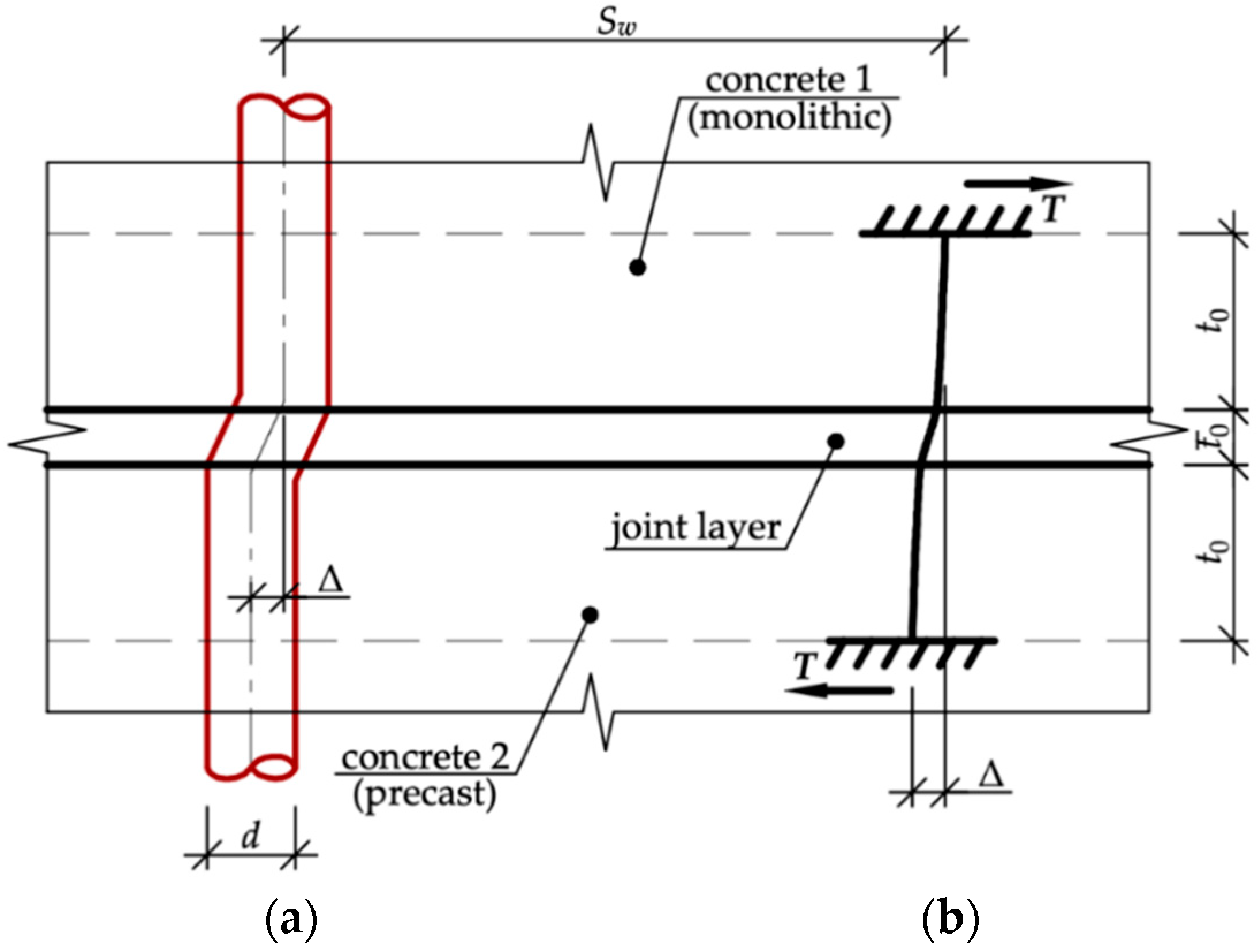
- Precast monolithic structural systems have higher robustness than pure precast solutions. However, the deformation and force distribution in such structures have a specific property due to the concentrated shear at the contact joint of the precast and monolithic parts of the section. This affects the cracking pattern, force redistribution, and energy dissipation.
2. Materials and Methods
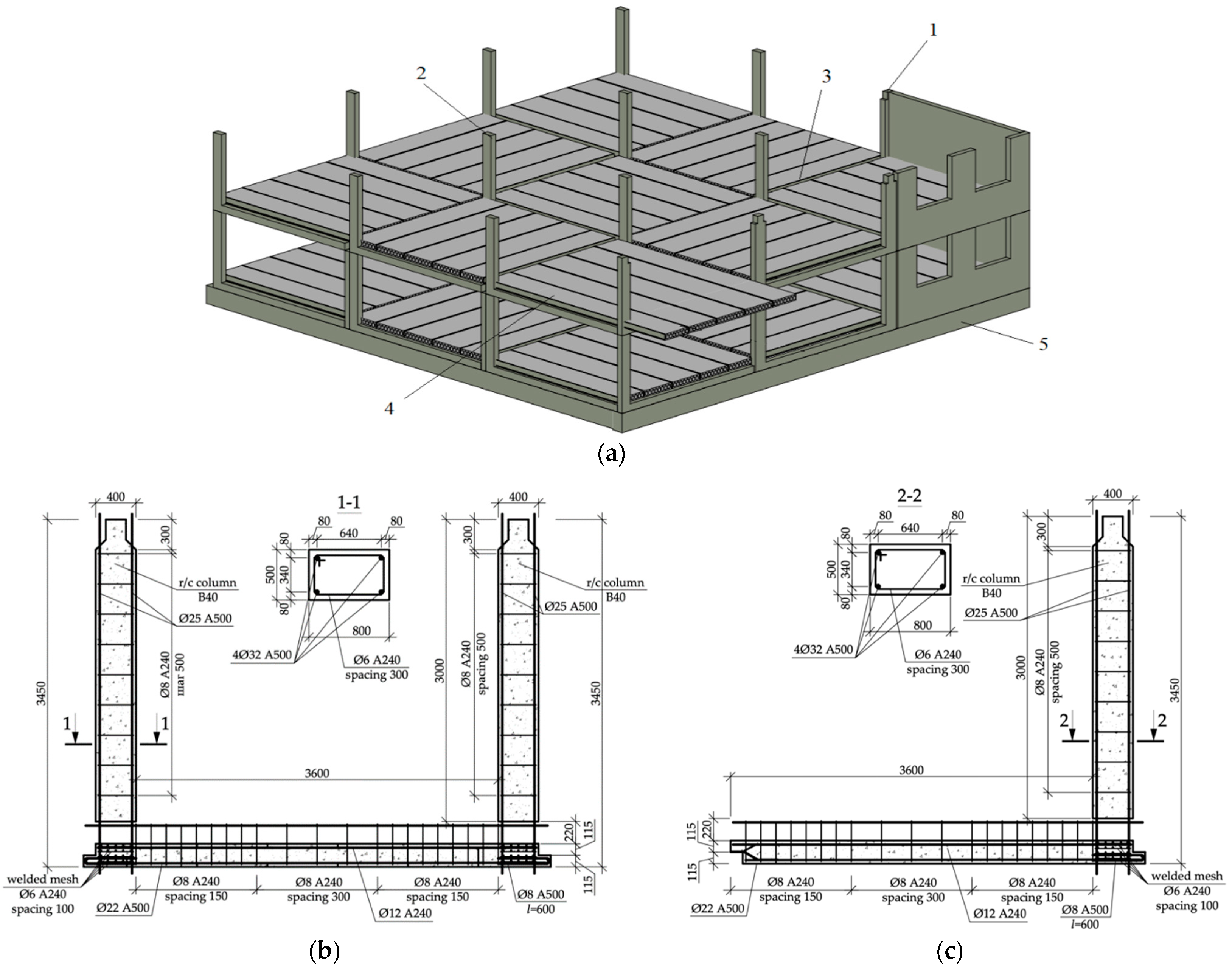
2.1. Design of a Precast Reinforced Concrete Frame System with Layered Beams
- −
- In comparison with frame structural systems consisting of prefabricated columns, beams, and floor slabs, the proposed structural solution has a smaller number of assembly units, which speeds up the installation process.
- −
- The use of monolithic concrete in the beams allows an increase in the level of static indeterminacy of the system in comparison with fully prefabricated ones. This has a positive effect on the operational characteristics of the system, such as the stiffness of the beam–column joints, and enables load transfer through alternative paths in the event of column removal.
- −
- In comparison to panel-wall structural solutions, this structural system exhibits a lower weight and offers greater flexibility in organizing the interior space of the building.
- −
- The utilization of layered elements can serve as an additional means of dissipating dynamic impact energy during localized failure within the structural system. The dissipation of impact energy in this case occurs due to the ductility of the contact joint area, the formation of a longitudinal crack, the decay of natural frequencies of structural vibrations, and the friction forces on the contact surface during the formation of a longitudinal crack.
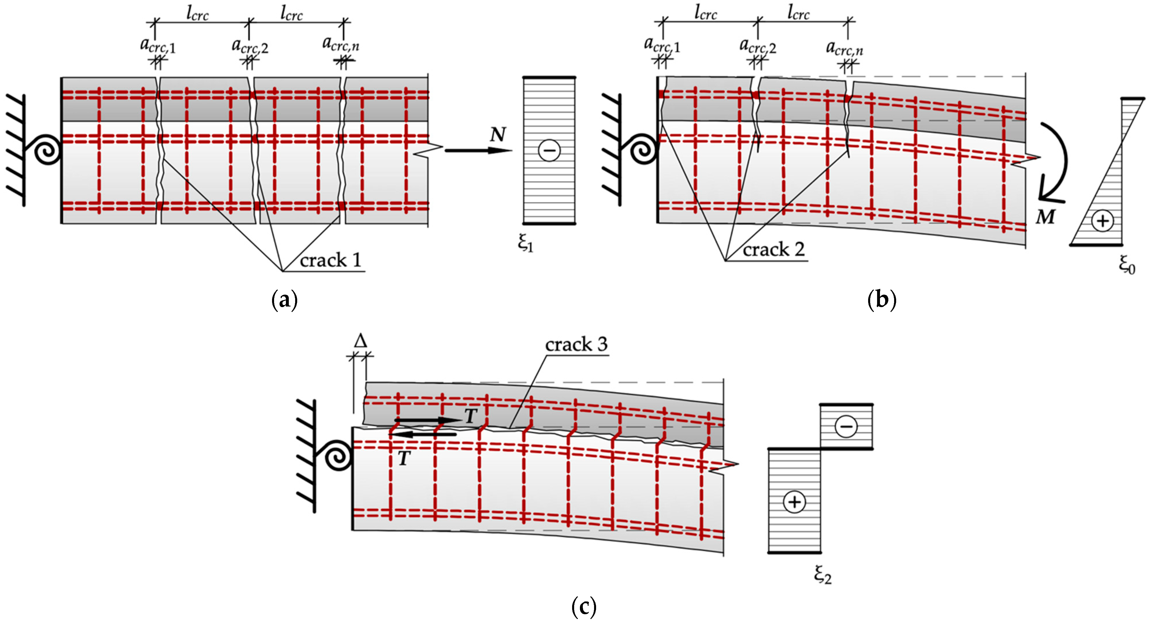
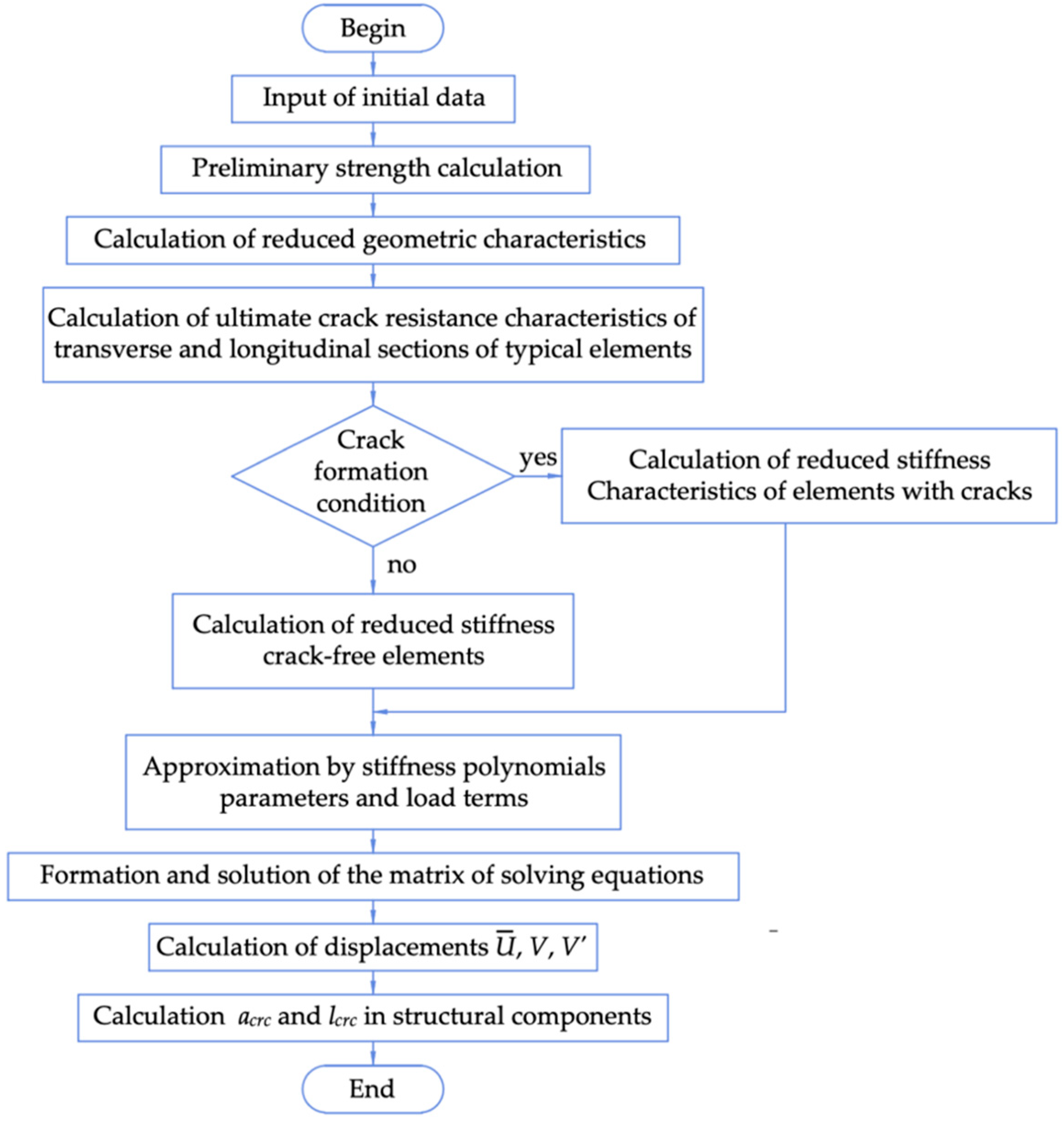
2.2. Method for Determining the Stress–Strain State in the Structural System
- −
- The bond strength of concrete of monolithic and prefabricated parts of the beam;
- −
- The deformability of transverse reinforcement bars under the action of dowel forces;
- −
- Boundary conditions in the end sections of the beams and anchoring of the longitudinal reinforcement in the prefabricated and monolithic parts of the beams in these sections.
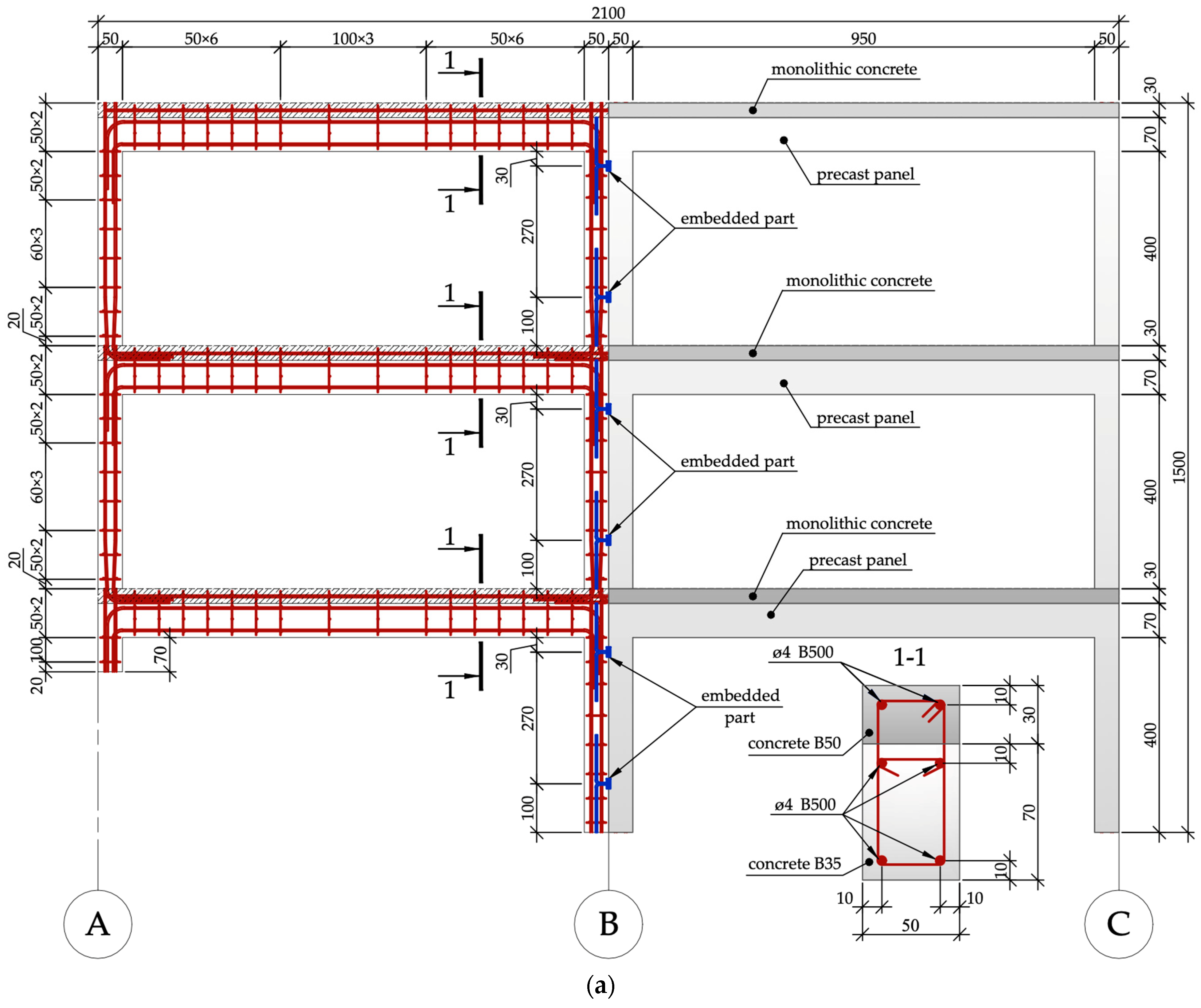
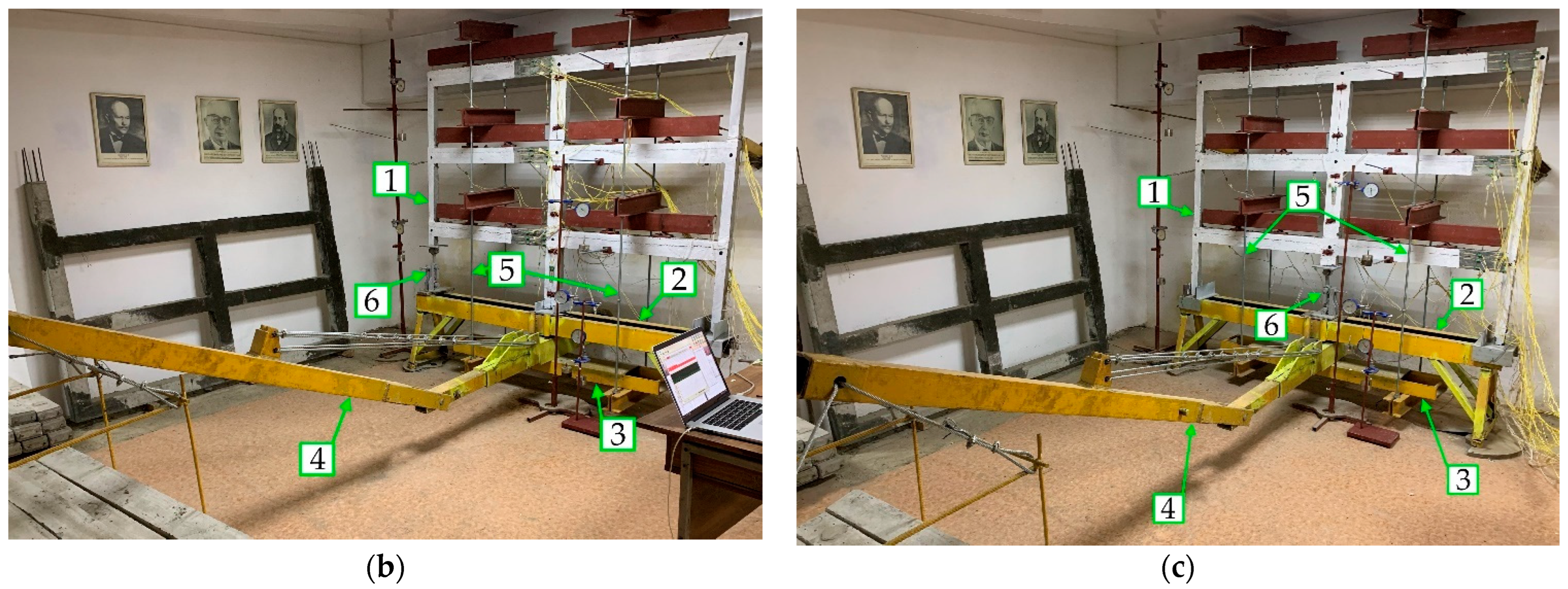
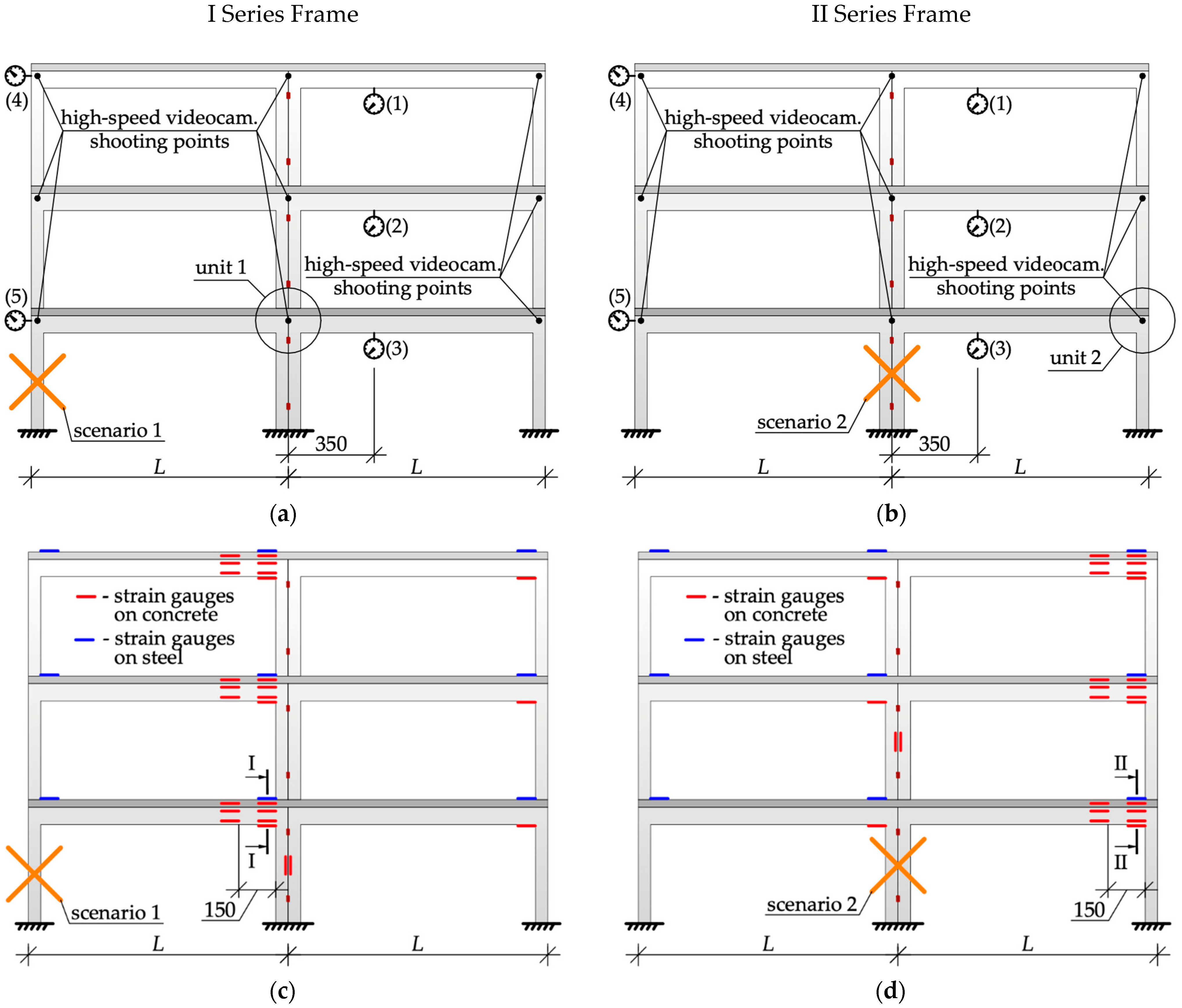
2.3. The Design of the Test Frames and the Method for Experimental Study
3. Results and Discussion
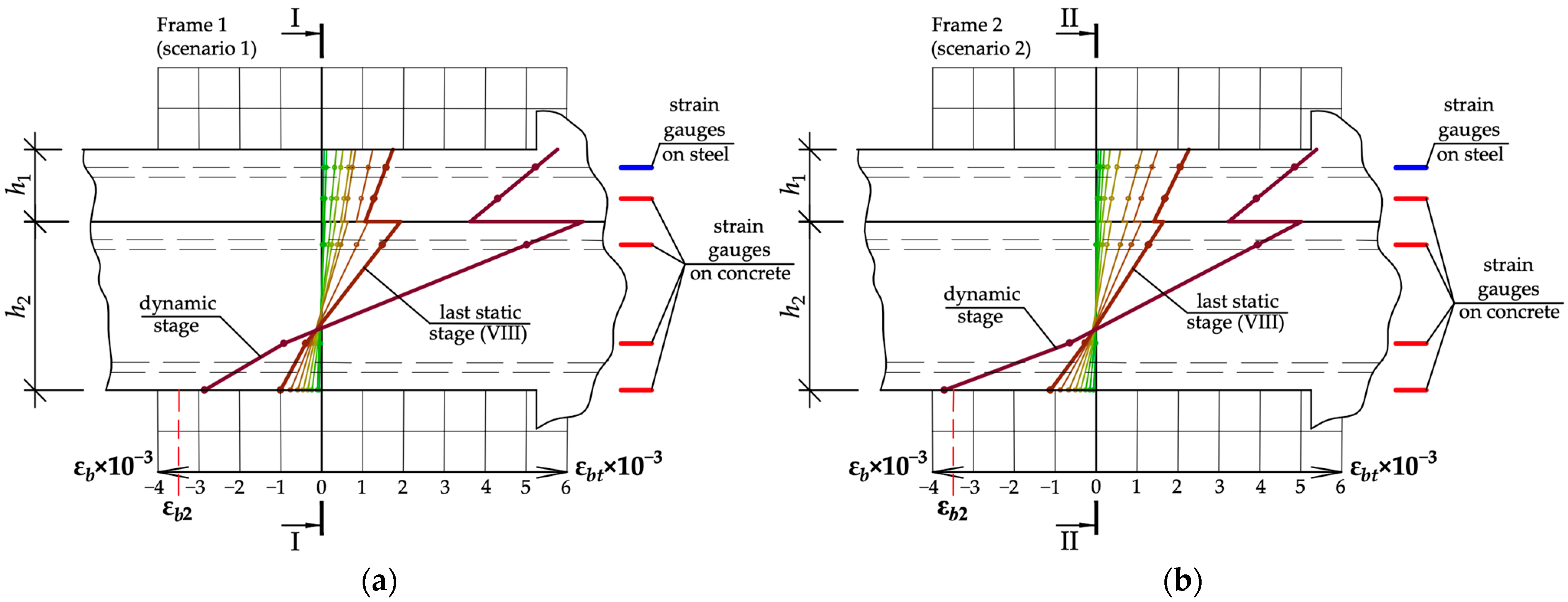
3.1. Experimental Results
3.2. Validation of the Proposed Semi-Analytical Model
4. Conclusions
- A new constructive system for a prefabricated monolithic frame of a fast-erecting multi-story building made of industrial elements of factory production is proposed. The proposed system includes two types of panel-frame elements of U-shaped and L-shaped profiles, monolithic bracing beams, and floors made of prefabricated multi-hollow slabs.
- For modeling such structural systems under accidental impacts, a two-level design scheme has been proposed. It implies the separation of substructures for advanced analysis. At the first level of simulation, the entire structural system is calculated. In the second stage, the model of the variational method proposed in this paper is used. On the basis of this model, the structural element adjacent to the zone of initial local failure is calculated. The use of the proposed numerical and analytical model in combination with two-level modeling allows one to reduce the time costs for simulation and to obtain the results in a form convenient for interpretation.
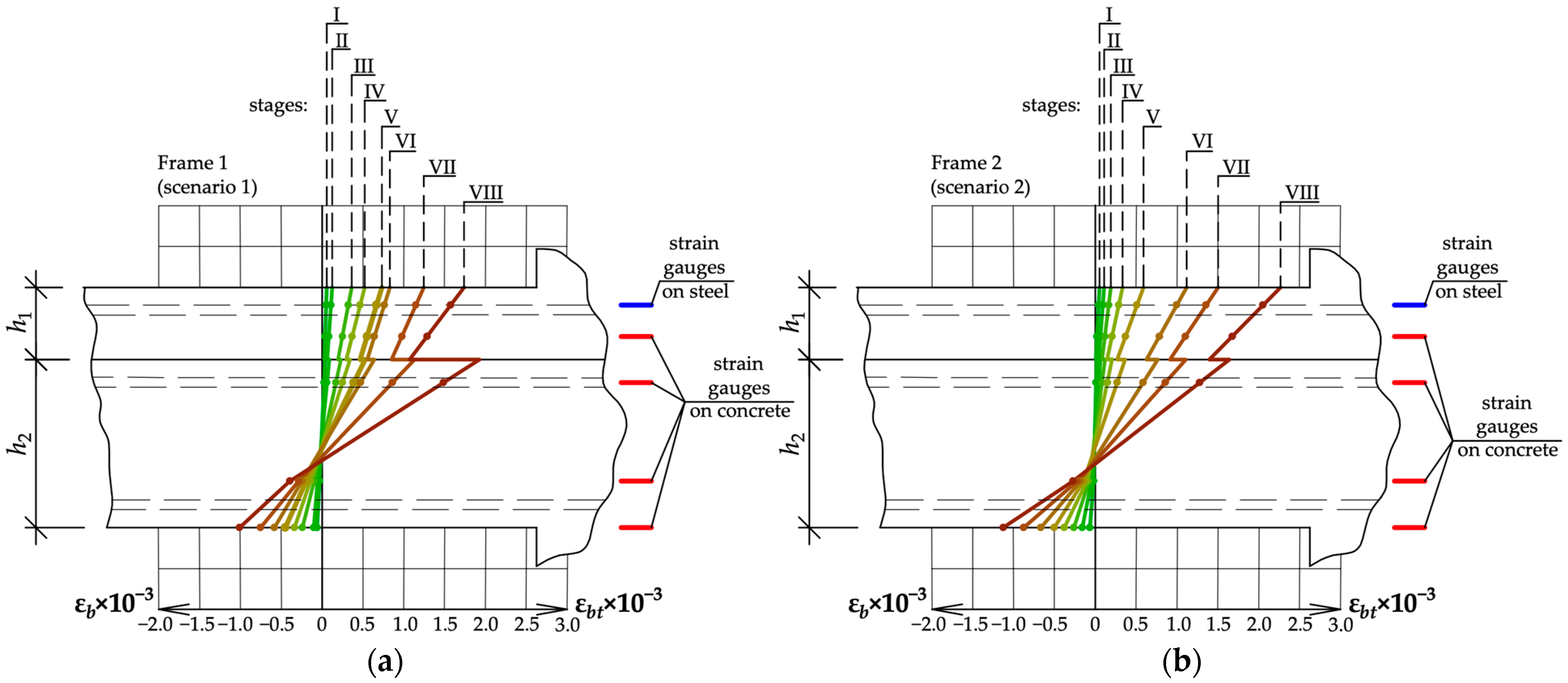
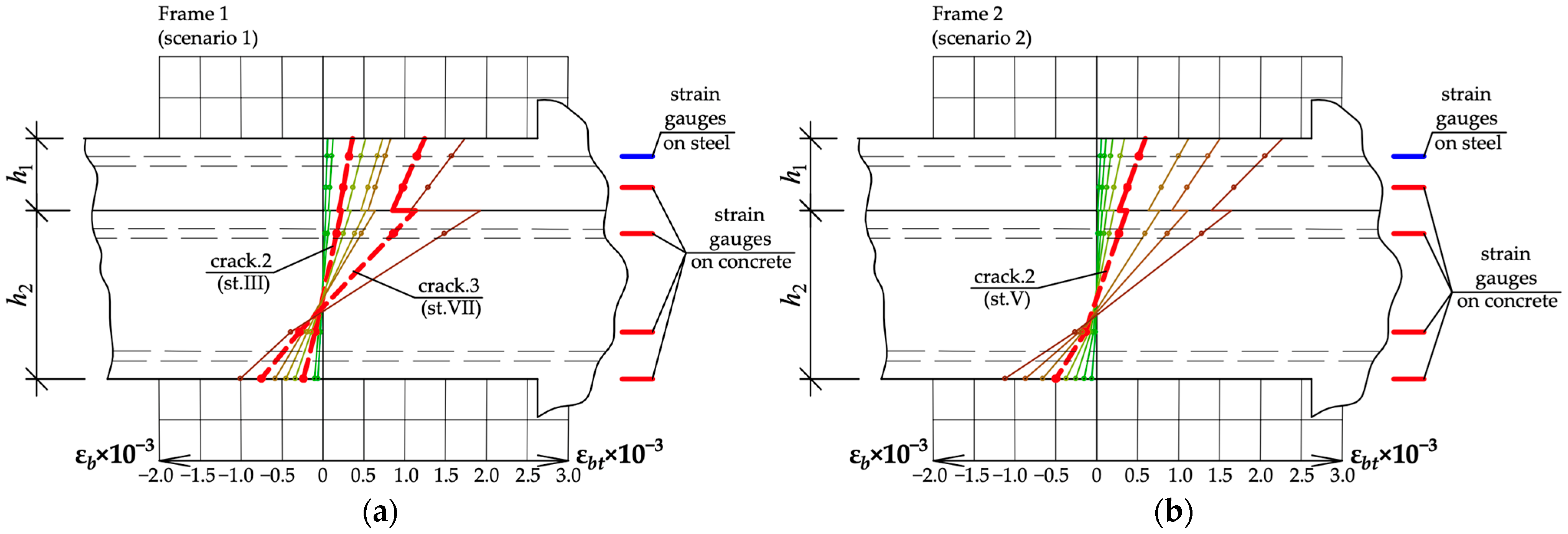
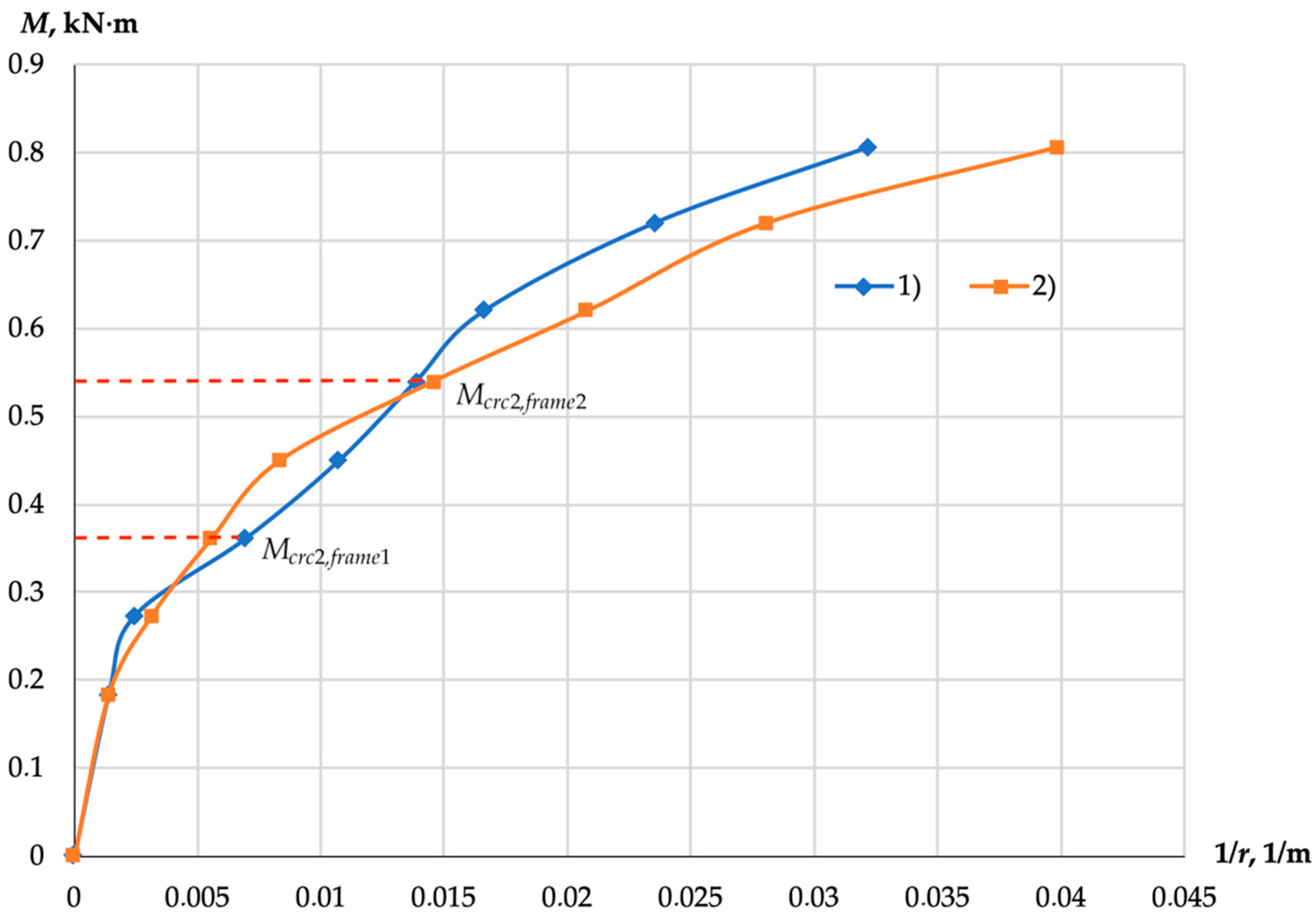
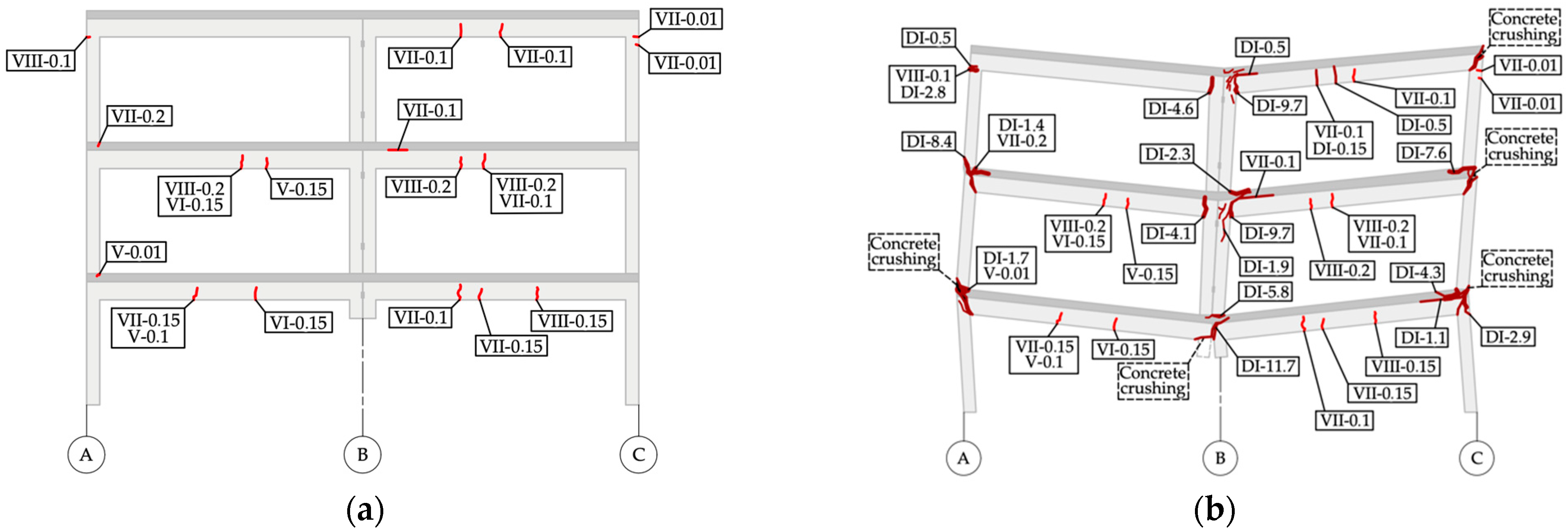
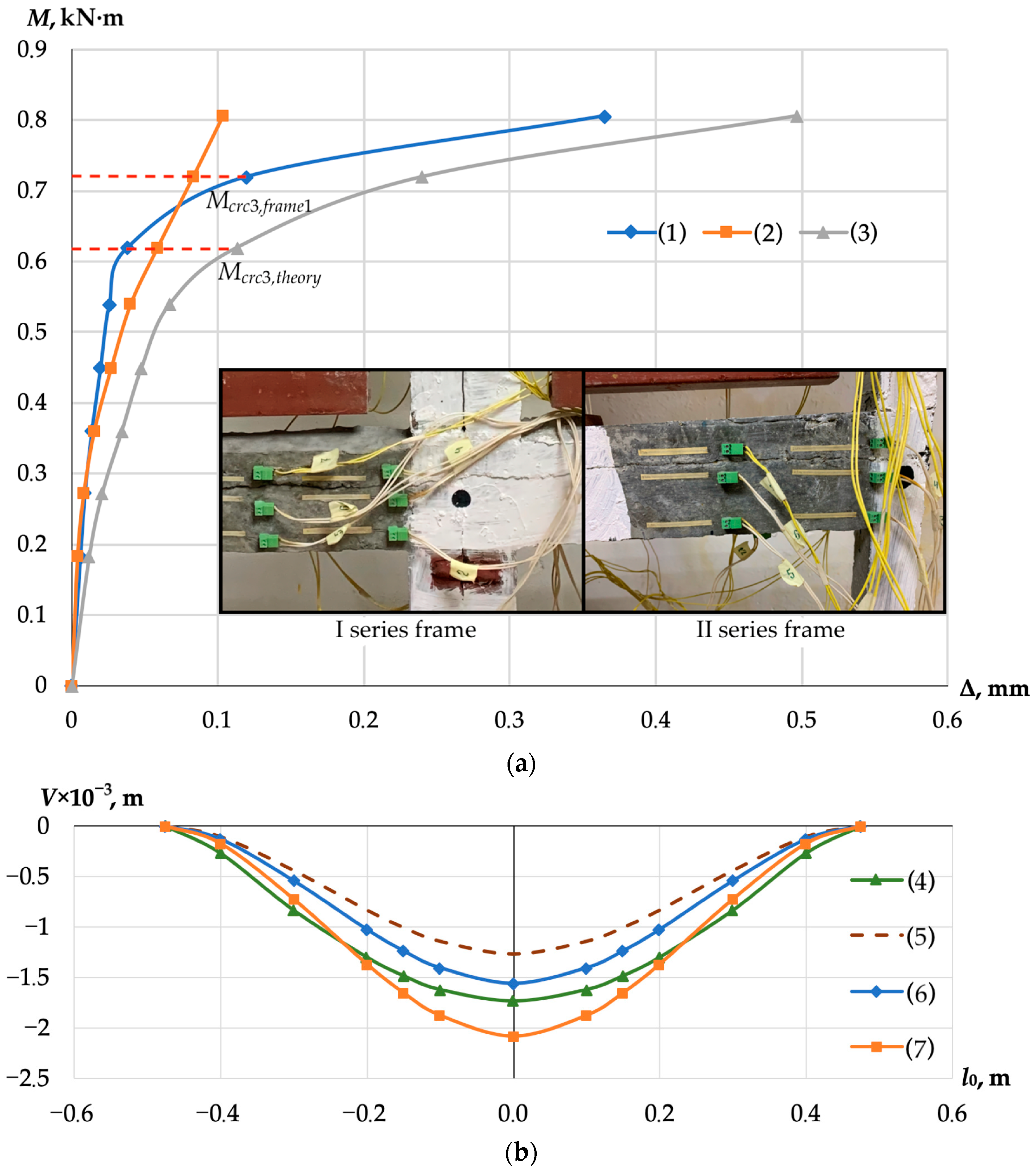
- Experimental studies of scale models of frames have confirmed the initial hypotheses adopted in the development of the analytical model for the analysis of layered beams of a prefabricated reinforced concrete frame system. Parameters of deformation diagrams as a result of accidental impact, as well as deformations in concrete and the reinforcement of the most loaded cross-sections of beams before and after crack formation under a two-stage mode of their loading, were experimentally obtained.
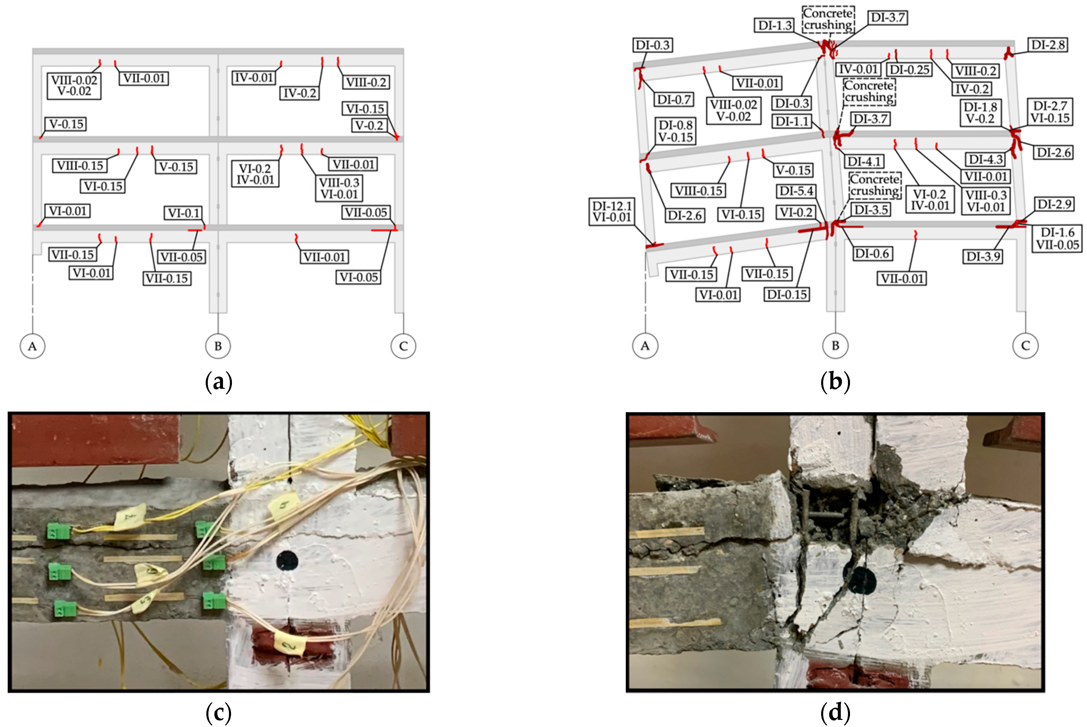
- Our analysis has demonstrated the influence of the interlayer contact joint on the deformation parameters of a precast reinforced concrete frame system under accidental impact due to column collapse. An important property of the deformation of such frames under a static–dynamic loading mode is the increased deformability of the interlayer contact joint, in which shear cracks can form.
Author Contributions
Funding
Data Availability Statement
Conflicts of Interest
References
- Pearson, C.; Delatte, N. Ronan Point Apartment Tower Collapse and Its Effect on Building Codes. J. Perform. Constr. Facil. 2005, 19, 172–177. [Google Scholar] [CrossRef]
- Tagel-Din, H.; Rahman, N.A. Simulation of the Alfred P. Murrah Federal Building Collapse Due to Blast Loads. In Proceedings of the AEI 2006: Building Integration Solutions—Proceedings of the 2006 Architectural Engineering National Conference, Omaha, NE, USA, 29 March–1 April 2006; Volume 2006, p. 32. [Google Scholar] [CrossRef]
- Belostotsky, A.M.; Pavlov, A.S. Long Span Buildings Analysys under Phisical, Geometic and Structural Nonlinearities Consideration. Int. J. Comput. Civ. Struct. Eng. 2010, 6, 80–86. [Google Scholar]
- Caredda, G.; Makoond, N.; Buitrago, M.; Sagaseta, J.; Chryssanthopoulos, M.; Adam, J.M. Learning from the Progressive Collapse of Buildings. Dev. Built Environ. 2023, 15, 100194. [Google Scholar] [CrossRef]
- Adam, J.M.; Parisi, F.; Sagaseta, J.; Lu, X. Research and Practice on Progressive Collapse and Robustness of Building Structures in the 21st Century. Eng. Struct. 2018, 173, 122–149. [Google Scholar] [CrossRef]
- Kokot, S.; Solomos, G. Progressive Collapse Risk Analysis: Literature Survey, Relevant Construction Standards and Guidelines—JRC 32253-2011; European Commission: Luxembourg, 2012; ISBN 9789279277344. [Google Scholar]
- Tamrazyan, A.G. Conceptual Approaches to Robustness Assessment of Building Structures, Buildings and Facilities. Reinf. Concr. Struct. 2023, 3, 62–74. [Google Scholar] [CrossRef]
- Lizahub, A.A.; Tur, A.V.; Tur, V.V. Probabilistic Approach for Assessing the Robustness of Structural Systems Made of Precast and Monolithic Reinforced Concrete. Build. Reconstr. 2023, 108, 93–105. [Google Scholar] [CrossRef]
- Yu, J.; Tan, K.H. Analytical Model for the Capacity of Compressive Arch Action of Reinforced Concrete Sub-Assemblages. Mag. Concr. Res. 2014, 66, 109–126. [Google Scholar] [CrossRef]
- Travush, V.I.; Fedorova, N.V. Survivability Parameter Calculation for Framed Structural Systems. Russ. J. Build. Constr. Archit. 2017, 33, 6–14. [Google Scholar]
- Savin, S.; Kolchunov, V.; Fedorova, N.; Tuyen Vu, N. Experimental and Numerical Investigations of RC Frame Stability Failure under a Corner Column Removal Scenario. Buildings 2023, 13, 908. [Google Scholar] [CrossRef]
- Almusallam, T.; Al-Salloum, Y.; Elsanadedy, H.; Tuan, N.; Mendis, P.; Abbas, H. Development Limitations of Compressive Arch and Catenary Actions in Reinforced Concrete Special Moment Resisting Frames under Column-Loss Scenarios. Struct. Infrastruct. Eng. 2020, 16, 1616–1634. [Google Scholar] [CrossRef]
- Akduman, S.; Aktepe, R.; Aldemir, A.; Ozcelikci, E.; Alam, B.; Sahmaran, M. Opportunities and Challenges in Constructing a Demountable Precast Building Using C&D Waste-Based Geopolymer Concrete: A Case Study in Türkiye. J. Clean. Prod. 2024, 434, 139976. [Google Scholar] [CrossRef]
- Yang, S.; Wu, B.; Wang, S.; Yang, G.; Wang, Z.; Xu, G.; Guo, H.; Li, L.; Bursi, O.S. Experimental Performance and Numerical Prediction of Precast Prestressed Concrete Frames Endowed with Shear Panel Dampers. J. Build. Eng. 2023, 77, 107461. [Google Scholar] [CrossRef]
- Zhao, F.; Xiong, F.; Cai, G.; Ge, Q.; Si Larbi, A. Seismic Behavior and Simplified Hysteretic Model of Precast Concrete Wall Panels with Bolted Connections under Cyclic Loading. Eng. Struct. 2023, 292, 116562. [Google Scholar] [CrossRef]
- Riedel, K.; Vollum, R.; Izzuddin, B.; Rust, G. Robustness Assessment of Precast Concrete Connections Using Component-Based Modelling. Structures 2024, 59, 105689. [Google Scholar] [CrossRef]
- Zeng, Y.; Li, Y.; Sun, M.; Noori, M.; Wei, X. Dynamic Progressive Collapse Response of 3D Monolithic Precast Concrete Frame Structures Considering Slab Effects. Structures 2024, 60, 105928. [Google Scholar] [CrossRef]
- Lin, K.; Lu, X.; Li, Y.; Guan, H. Experimental Study of a Novel Multi-Hazard Resistant Prefabricated Concrete Frame Structure. Soil Dyn. Earthq. Eng. 2019, 119, 390–407. [Google Scholar] [CrossRef]
- Klyueva, N.V.; Kolchunov, V.I.; Rypakov, D.A.; Bukhtiyarova, A.S. Residential and Public Buildings of Industrially Manufactured Reinforced Concrete Frame-Panel Elements. Zhilishchnoe Stroit. 2015, 5, 69–75. [Google Scholar]
- Fedorova, N.V.; Savin, S.Y.; Kolchunov, V.I.; Moskovtseva, V.S.; Amelina, M.A. Building structural system made of industrial frame-panel elements. Build. Reconstr. 2023, 107, 70–81. [Google Scholar] [CrossRef]
- Nikolaev, S.V. Panel and Frame Buildings of New Generation. Zhilishchnoe Stroit. 2013, 8, 2–9. [Google Scholar]
- Nikolaev, N.S. Architectural and Urban Planning System of Panel and Frame Construction. Zhilishchnoe Stroit. 2016, 3, 15–25. [Google Scholar]
- Ostretsov, V.M.; Magay, A.A.; Voznyuk, A.B.; Gorelkin, A.N. A Flexible System of Panel Construction. Zhilishchnoe Stroit. 2011, 3, 8–11. [Google Scholar]
- SP 385.1325800.2018; Protection of Buildings and Structures against Progressive Collapse. Design Code. Basic Statements. National Building Code of Russian Federation; Ministry of Construction, Housing and Utilities: Moscow, Russia, 2018. Available online: https://docs.cntd.ru/document/551394640 (accessed on 14 May 2024).
- ASCE 76-23; Standard for Mitigation of Disproportionate Collapse Potential in Buildings and Other Structures. American Society of Civil Engineers: Reston, VA, USA, 2023; 62p. [CrossRef]
- Adam, J.M.; Buitrago, M.; Bertolesi, E.; Sagaseta, J.; Moragues, J.J. Dynamic Performance of a Real-Scale Reinforced Concrete Building Test under a Corner-Column Failure Scenario. Eng. Struct. 2020, 210, 110414. [Google Scholar] [CrossRef]
- Sheffield, C.; Kersul, A.; Hoon, V.; Amini, A. An Instrumented Full-Scale Building Progressive Collapse Test. In Proceedings of the 14th International Symposium on Interaction of the Effects of Munitions with Structures, Seattle, WA, USA, 19–23 September 2011. [Google Scholar]
- Sasani, M.; Sagiroglu, S. Progressive Collapse Resistance of Hotel San Diego. J. Struct. Eng. 2008, 134, 478–488. [Google Scholar] [CrossRef]
- Ahmadi, R.; Rashidian, O.; Abbasnia, R.; Mohajeri Nav, F.; Usefi, N. Experimental and Numerical Evaluation of Progressive Collapse Behavior in Scaled RC Beam-Column Subassemblage. Shock Vib. 2016, 2016, 3748435. [Google Scholar] [CrossRef]
- Yu, J.; Tan, K.-H. Experimental and Numerical Investigation on Progressive Collapse Resistance of Reinforced Concrete Beam Column Sub-Assemblages. Eng. Struct. 2013, 55, 90–106. [Google Scholar] [CrossRef]
- Lim, N.S.; Tan, K.H.; Lee, C.K. Experimental Studies of 3D RC Substructures under Exterior and Corner Column Removal Scenarios. Eng. Struct. 2017, 150, 409–427. [Google Scholar] [CrossRef]
- Du, K.; Bai, J.; Teng, N.; Yan, D.; Sun, J. Experimental Investigation of Asymmetrical Reinforced Concrete Spatial Frame Substructures against Progressive Collapse under Different Column Removal Scenarios. Struct. Des. Tall Spec. Build. 2020, 29, e1717. [Google Scholar] [CrossRef]
- Zhang, W.-X.; Wu, H.; Zhang, J.-Y.; Hwang, H.-J.; Yi, W.-J. Progressive Collapse Test of Assembled Monolithic Concrete Frame Spatial Substructures with Different Anchorage Methods in the Beam–Column Joint. Adv. Struct. Eng. 2020, 23, 1785–1799. [Google Scholar] [CrossRef]
- Kai, Q.; Li, B. Dynamic Performance of RC Beam-Column Substructures under the Scenario of the Loss of a Corner Column—Experimental Results. Eng. Struct. 2012, 42, 154–167. [Google Scholar] [CrossRef]
- Ren, P.; Li, Y.; Lu, X.; Guan, H.; Zhou, Y. Experimental Investigation of Progressive Collapse Resistance of One-Way Reinforced Concrete Beam-Slab Substructures under a Middle-Column-Removal Scenario. Eng. Struct. 2016, 118, 28–40. [Google Scholar] [CrossRef]
- Ma, F.; Gilbert, B.P.; Guan, H.; Lu, X.; Li, Y. Experimental Study on the Progressive Collapse Behaviour of RC Flat Plate Substructures Subjected to Edge-Column and Edge-Interior-Column Removal Scenarios. Eng. Struct. 2020, 209, 110299. [Google Scholar] [CrossRef]
- Kiakojouri, F.; Zeinali, E.; Adam, J.M.; De Biagi, V. Experimental Studies on the Progressive Collapse of Building Structures: A Review and Discussion on Dynamic Column Removal Techniques. Structures 2023, 57, 105059. [Google Scholar] [CrossRef]
- Tuyen, V.N.; Ivanovich, K.V.; Vitalyevna, F.N. Dynamic Response Model of Reinforced Concrete Building Frame under Column Removal Scenario. Structures 2024, 63, 106356. [Google Scholar] [CrossRef]
- Anil, Ö.; Altin, S. An Experimental Study on Reinforced Concrete Partially Infilled Frames. Eng. Struct. 2007, 29, 449–460. [Google Scholar] [CrossRef]
- Li, S.; Shan, S.; Zhai, C.; Xie, L. Experimental and Numerical Study on Progressive Collapse Process of RC Frames with Full-Height Infill Walls. Eng. Fail. Anal. 2016, 59, 57–68. [Google Scholar] [CrossRef]
- Shan, S.; Li, S.; Xu, S.; Xie, L. Experimental Study on the Progressive Collapse Performance of RC Frames with Infill Walls. Eng. Struct. 2016, 111, 80–92. [Google Scholar] [CrossRef]
- Sharaky, I.A.; Seleem, M.H.; Elamary, A.S. Minimizing the Crumb Rubber Effects on the Flexural Behaviour of the Layered RC Beams Cast Using Rubberized Concrete with or without Recycled Tire Steel Fibers. Constr. Build. Mater. 2023, 400, 132503. [Google Scholar] [CrossRef]
- Abbas, Y.M.; Khan, M.I. Behavioral Response of Reinforced Concrete Beams with Ultra-Ductile Fiber-Reinforced Cementitious Composite Layers—Experiments, Models and Reinforcement Limits. J. Build. Eng. 2023, 77, 107475. [Google Scholar] [CrossRef]
- Dung Do, T.M.; Khai Lam, T.Q. Cracks in Single-Layer and Multi-Layer Concrete Beams. Transp. Res. Procedia 2022, 63, 2589–2600. [Google Scholar] [CrossRef]
- Slaitas, J. Universal Bond Models of FRP Reinforcements Externally Bonded and Near-Surface Mounted to RC Elements in Bending. Materials 2024, 17, 493. [Google Scholar] [CrossRef]
- Armonico, A.; Michel, L.; Saidi, M.; Ferrier, E. Experimental Study on the Effect of Steel Reinforcement Ration on the Cracking Behaviour of FRP-Strengthened RC Elements. Buildings 2024, 14, 950. [Google Scholar] [CrossRef]
- Granata, M.F. Seismic Retrofit of Concrete Buildings Damaged by Corrosion: A Case Study in Southern Italy. Buildings 2024, 14, 1064. [Google Scholar] [CrossRef]
- Tho, V.D.; Korol, E.; Rimshin, V.; Anh, P.T. Model of Stress-Strain State of Three-Layered Reinforced Concrete Structure by the Finite Element Methods. Int. J. Comput. Civ. Struct. Eng. 2022, 18, 62–73. [Google Scholar] [CrossRef]
- Butean, C.; Heghes, B. Flexure Behavior of a Two Layer Reinforced Concrete Beam. Procedia Manuf. 2020, 46, 110–115. [Google Scholar] [CrossRef]
- Luu, X.-B. Finite Element Modelling of Reinforced Concrete Beam Strengthening Using Ultra-High Performance Fiber-Reinforced Shotcrete Combined with Reinforcing Bars. Structures 2024, 60, 105794. [Google Scholar] [CrossRef]
- Kolchunov, V.I.; Dem’yanov, A.I. The Modeling Method of Discrete Cracks and Rigidity in Reinforced Concrete. Mag. Civ. Eng. 2019, 88, 60–69. [Google Scholar] [CrossRef]
- Kolchunov, V.I.; Dem’yanov, A.I. The Modeling Method of Discrete Cracks in Reinforced Concrete under the Torsion with Bending. Mag. Civ. Eng. 2018, 81, 160–173. [Google Scholar] [CrossRef]
- Rzhanitsyn, A.R. Layered Bars and Plates; Stroyizdat: Moscow, Russia, 1986. [Google Scholar]
- Kolchunov, V.I.; Panchenko, L.A. Calculation of Composite Thin-Walled Structures; Publishing House ASV: Moscow, Russia, 1999. [Google Scholar]
- SP 63.13330.2018; Concrete and Reinforced Concrete Structures. General Provision. Basic Statements. Standardinform: Moscow, Russia, 2020. Available online: https://docs.cntd.ru/document/554403082 (accessed on 1 June 2024).
- Bazant, Z.P.; Kwon, Y.W. Failure of slender and stocky reinforced concrete columns: Tests of size effect. Mater. Struct. 1994, 27, 79–90. [Google Scholar] [CrossRef]
- Pham, A.T.; Brenneis, C.; Roller, C.; Tan, K.H. Blast-induced dynamic responses of reinforced concrete structures under progressive collapse. Mag. Concr. Res. 2022, 74, 850–863. [Google Scholar] [CrossRef]


| The Right-Hand Sides of the Equations | |||
|---|---|---|---|
| 0 | |||
| − | 0 | ||
| − | − |
| The Right-Hand Sides of the Equations | |||
|---|---|---|---|
| 0 | |||
| 0 | |||
Disclaimer/Publisher’s Note: The statements, opinions and data contained in all publications are solely those of the individual author(s) and contributor(s) and not of MDPI and/or the editor(s). MDPI and/or the editor(s) disclaim responsibility for any injury to people or property resulting from any ideas, methods, instructions or products referred to in the content. |
© 2024 by the authors. Licensee MDPI, Basel, Switzerland. This article is an open access article distributed under the terms and conditions of the Creative Commons Attribution (CC BY) license (https://creativecommons.org/licenses/by/4.0/).
Share and Cite
Kolchunov, V.I.; Fedorova, N.V.; Savin, S.Y.; Kaydas, P.A. Progressive Collapse Behavior of a Precast Reinforced Concrete Frame System with Layered Beams. Buildings 2024, 14, 1776. https://doi.org/10.3390/buildings14061776
Kolchunov VI, Fedorova NV, Savin SY, Kaydas PA. Progressive Collapse Behavior of a Precast Reinforced Concrete Frame System with Layered Beams. Buildings. 2024; 14(6):1776. https://doi.org/10.3390/buildings14061776
Chicago/Turabian StyleKolchunov, Vitaly I., Natalia V. Fedorova, Sergei Y. Savin, and Pavel A. Kaydas. 2024. "Progressive Collapse Behavior of a Precast Reinforced Concrete Frame System with Layered Beams" Buildings 14, no. 6: 1776. https://doi.org/10.3390/buildings14061776
APA StyleKolchunov, V. I., Fedorova, N. V., Savin, S. Y., & Kaydas, P. A. (2024). Progressive Collapse Behavior of a Precast Reinforced Concrete Frame System with Layered Beams. Buildings, 14(6), 1776. https://doi.org/10.3390/buildings14061776