Article

Design and Characteristics of a Single-Storey Hybrid Wood–Soil Structure

1
Department of Construction Engineering, The American University in Cairo, New Cairo 11835, Egypt
2
Arabia Contracting Inc., Cairo 4450113, Egypt
3
Housing and Building National Research Center, Cairo 12611, Egypt
4
ALDAR Engineering, Cairo 11727, Egypt
*
Author to whom correspondence should be addressed.
Buildings 2024, 14(6), 1785; https://doi.org/10.3390/buildings14061785
Submission received: 27 April 2024 / Revised: 30 May 2024 / Accepted: 11 June 2024 / Published: 13 June 2024
(This article belongs to the Special Issue Performance Analysis of Timber Composite Structures)

Abstract

:
The need to reduce the effects of climate change has been increasing. One of the pathways to answer such a need is green construction. Hybrid wood–soil (HWS) structures are eco-friendly in addition to being cost-effective. Within this study, a single-storey building has been architecturally and structurally designed and tested. A conventional reinforced concrete (RC) structural system was designed and considered as a control case to be compared to the design at hand, which is an HWS system incorporating locally cultivated Casuarina Glauca wood and an in situ earth-based mixture. The two design alternatives are compared in terms of cost and carbon emissions. The HWS has proven to be economically viable and eco-friendly when compared to RC. The following stage within the research was to validate that the HWS structure will be structurally sound when erected. First, the effectiveness of the finger jointing process of the wooden members was experimentally assessed through performing bending tests on a finger-jointed specimen. Furthermore, half-scale models of one room within the structure have been manufactured from Casuarina Glauca wood and tested laterally to investigate the resistance of the HWS structural system to lateral loads. The first model was tested laterally without the earth-based infill and plaster materials to assess the behavior of the structural elements and measure its deformations. The second model was tested after applying the earth-based materials to obtain the true structural behavior of the system and the effect of the earth-based materials on its resistance to lateral loads. The results were used to assess the degree of the structural effectiveness of this HWS and the contribution of its components to its lateral stiffness.

1. Introduction

Modernity has placed mankind in two major coupled problems, which are climate change and the global housing crisis. One of the core reasons for both of the two problems is the mere fact that the most currently utilized building materials depend on high levels of industrialization, making them expensive and non-ecofriendly as these materials are directly responsible for consuming a lot of energy and emitting considerable amounts of CO2 throughout their manufacturing processes in addition to being expensive in non-industrialized nations [1].
The CO2 emissions due to the cement industry are one of the main contributors to the high share of the construction-related industries in the global CO2 emissions [2]. The more serious fact is that these CO2 emissions due to cement manufacturing have even been significantly on the rise in the past years [3]. The other contributor to the construction-related CO2 emissions is the steel industry, which contributes more than one quarter of the global CO2 emissions from the global industrial sector [4]. To reduce these amounts of emissions more effectively, it is imperative to continuously invent new environmentally friendly and sustainable building materials and technologies or further utilize the already available sustainable building technologies and make them more mass producible to have a significant effect on reducing global CO2 emissions. However, this reduction in CO2 emissions should not be on account of increasing building costs, which are already increasing.
On the other hand, more than one-sixth of the global population resides in slums [5]. This problem is more serious in developing countries in which more than one-fifth of the population lives in inhumane housing because of rising housing costs [6]. With the global increase in both population and inflation, it is anticipated that by 2030 three out of every five individuals will live in substandard conditions all over the globe [7]. In Egypt, more than 55 million people constituting half of the population reside in rural areas, and the cost of construction has increased dramatically over the past three decades due to increases in the price of cement, steel, and masonry, connected to the devaluation of the local currency [8]. This is especially true considering that reinforced concrete (RC) is the most widely used construction materials in Egypt [9].
One of the solutions to these coupled issues could be developing and using building materials from waste; however, this is not always economically feasible due to significant industrial processes needed to turn these wastes into functioning building materials of sufficient characteristics [1]. Consequently, using inexpensive raw resources, such as underutilized indigenous wood, together with different earth construction alternatives is one of the viable ways to lower the costs of construction materials.
Although earth construction is one of the most ancient construction technologies, it was nearly abandoned due to the low strength of adobe earth bricks/blocks that are not compressed enough to give them sufficient strength to be used in cases where the loads are not small enough unless innovative materials are utilized within the earth-based mixtures [10]. Hence, over the past few years, the use of modern earth construction has grown significantly, in which earth could be poured, rammed, or compacted in some methods of construction [11]. Rammed earth is one of the ancient earth construction techniques involving the use of formwork to mold earth mixtures and ramming the earth. This technique has been modernized through increasing the ramming force to reduce the porosity and increase the strength and possibly altering the earth mixtures to have more efficient stabilizers [12]. Meanwhile, compressed earth construction is very similar to adobe earth construction; however, instead of the earth mixture being just molded, it will be also compressed either using a fully mechanized press or a semi-manual press [11].
Meanwhile, although ancient civilizations saw the first use of wood as a structural component of an earthen edifice, wood is not widely used in arid countries like Egypt. This is because in arid countries, wood is mostly imported, which makes it an uneconomical construction material [13]. However, the solution to such a problem would be resorting to using wood species from locally farmed trees that do not consume a lot of water in addition to even being possible to be cultivated on wastewater, such as the Casuarina species of trees [13]. Using such alternatives has been proven to be both eco-friendly and cost-effective when compared to using steel or reinforced concrete due to these trees being cultivated locally, and hence not affected by the currency exchange rate, and being farmed on wastewater, guaranteeing a sustainable and eco-friendly agricultural process [13,14,15].
A prior investigation looked at the mechanical characteristics of various Casuarina species [16]. The study has shown that one of these species called Casuarina Glauca was more robust than several oaks. The research was expanded to examine the wood’s qualities at various moisture percentages, and it was discovered that this wood had stronger properties than numerous others at each of the moisture percentages included in the study [17]. These data were used to design, produce, and test a Casuarina glauca wooden K-truss that was shown to survive a load exceeding the design load and satisfied both the strength and the deflection design criteria [13]. That wood’s great strength prompted researchers to investigate using it to erect a truss having a span of 12 m and experimentally demonstrated that the Casuarina glauca truss members may withstand loads even higher than the design loads while being of a significantly low cost when compared to that of a steel truss [14].
Consequently, it is apparent that using hard wood, such as Casuarina Glauca, and earth together within one system would be an ideal solution utilizing the merits of both materials. Hybrid wood–soil systems (HWS) are one of the technologies that involve both earth and wood and are becoming more widely used. Within such systems, wooden members act as the structural load-bearing elements while the earth-based mixtures used as infill and plastering perform the architectural functions of thermal insulation and sound isolation [15]. Meanwhile, although earth shelters’ ability to conserve energy has been demonstrated [18], there are few investigations on the structural traits of HWS.
As far as the authors are aware, only one research team has structurally developed an HWS system from Casuarina wood, structurally tested a scaled model of it, and evaluated its affordability and environmental friendliness. In that investigation, a one-storey HWS building was erected and tested structurally in the horizontal plane until it structurally failed. After that, the model was tested after the structural design had been modified by stiffening the connections and bracings in each direction. However, this model included only the wooden members, and the effect of the earth-based infill and plaster was not taken into consideration. Meanwhile, the designed RC counterpart was used as a control to compare the cost of the construction as well as the cost per square meter. Additionally, the amount of CO2 released per square meter was determined and contrasted with that from the RC control system [15].
However, all the previously mentioned studies included analysis, design, and testing of wooden structures with a relatively regular structural system. Hence, there is an obvious research gap as it is very rare to find an irregular structure consisting of HWS walls that is documented and proven to be cost-effective and eco-friendly. Another existing research gap is the fact that the HWS system has never been structurally tested with and without the infill and plastering earth-based mixtures to assess their actual contribution in resisting loads. Consequently, within the study at hand, an irregular structure including domes, vaults, and a skylight is being analyzed and designed to withstand gravity loads and wind loads in lieu of the HWS system developed by [15]. Furthermore, the cost-effectiveness of the building and its eco-friendliness are both studied and compared to other alternatives that could be typically used to design and construct such a building. Finally, two three-dimensional models of an HWS structure were constructed and structurally tested till failure. One model was not infilled, while the other was infilled with the earth-based mixtures used for plastering and infill. This was performed to assess whether the earth-based mixtures have a significant contribution to the structural performance of the HWS structure or if they are just performing the architectural purposes in addition to thermal and acoustic insulation.

2. Materials and Methods

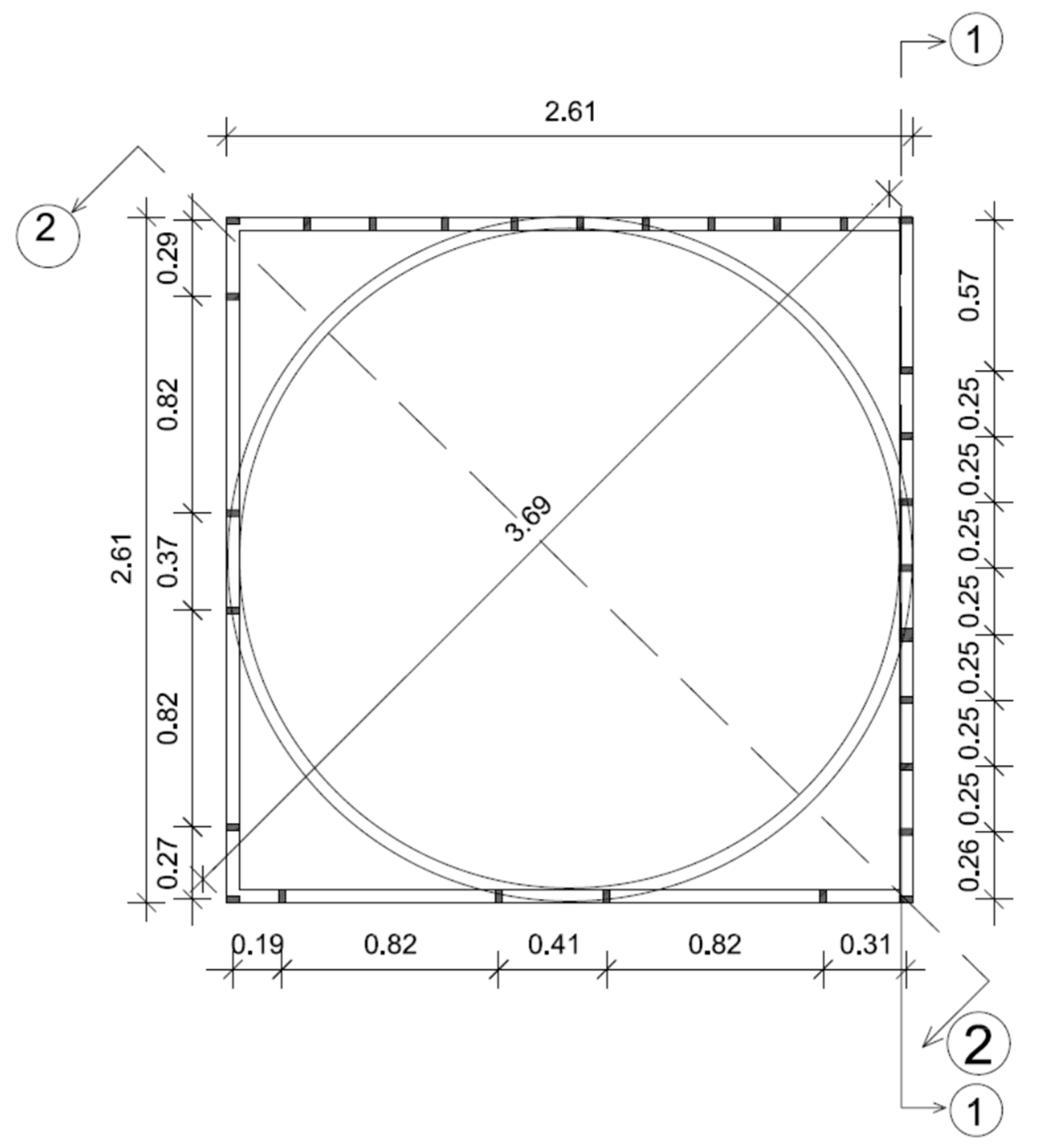
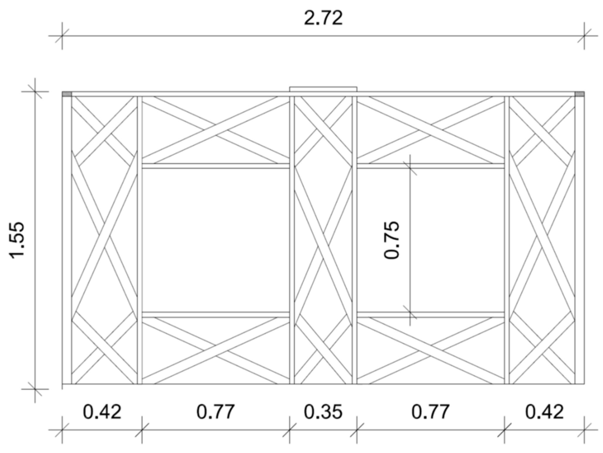
2.1. Structural Design

The building subject to investigation is a prototype for a nursery in Siwa, Egypt. Thus, the construction costs were to be cut down by using HWS as a replacement for RC, as this nursery is a one-storey structure with a non-accessible roof, resulting in low live loads. The structure covers an area of 18 m × 15.75 m. The structural system consisting of domes, vaults, and a skylight supported on wooden members was set as shown in Figure 1. This structural system is similar to the structural system previously designed by [15] in terms of the elements resisting the lateral forces, which are the HWS walls, however, with a totally different roof. Hence, the connections used in the design at hand are the same connections specified by [15] except for the connections connecting the ring beams and the skylight to the beams and studs.
The HWS system incorporated the wooden members within the walls to be designed from Casuarina Glauca wood, having an average compressive strength of 32 MPa (parallel to the grain), an average tensile strength of 163 MPa, and an average bending strength of 62 MPa as reported in the study by [16]. Since the coefficients of variation (COV) ranging between 9% and 10% of all these strengths were mean values [16], these mean values were all conservatively multiplied by 0.8 to reduce their values by two standard deviations and hence obtain the design strengths. Apart from the beams supporting the skylight, all wooden joists, stringers, and studs were safely designed to have a cross-section of 100 mm × 50 mm. Meanwhile, the skylight joists were 150 mm × 50 mm. The design utilized the typical connections shown in Figure 2, previously tested by the research group and reported in the study by [15]. The stabilized earth mixture used is based on the mix described within the Egyptian patent application no. 1948–2019 which includes percentages of clay, lime, hay, and sand with the possible inclusion of small percentages of cement (up to 4%) depending on the component strengths.
The structural design took into account both live and wind loads as well as the structure’s own weight when analyzing the various design load combinations according to the Egyptian code of loads [19]. As a result, the live load for the roof that was inaccessible was 800 N/m2. Meanwhile, the building is located in Siwa, is less than 10 m high, experiences wind speeds of 42 m/s (as Siwa has the same wind speed of Marsa Matrouh specified in the Egyptian code), and has a terrain factor of 1 as the site is located in a flat area. The design wind load was 1200 N/m2 with an 880 N/m2 suction on the roof, a 570 N/m2 suction on the leeward side, and an 880 N/m2 pressure on the windward side using the code factors specified in the Egyptian code of loads, with a total lateral wind load of 1450 N/m2 [19].
When it comes to the design criteria, the most important idea is that the wooden members alone are responsible for resisting the loads structurally, with the earth-based mix serving solely as infill for the architectural functions of thermal insulation and acoustic isolation. However, in this case at hand, the infill earth-based mixture together with the earth-based plastering mixture played another role, which is to transfer the loads on the domes to the wooden ring beams and from the vaults to the adjacent wooden beams. The structural system of the HWS also includes lateral wooden X-bracing strengthening the system in the horizontal plane connected to the wooden beams and studs in the manner specified by [15]. Accordingly, and as the two earth-based mixtures are performing different functions, they had different proportions of loam, clay, sand, and lime depending on the targeted properties. The stabilized earth-based mixture used is based on the earth-based mix described within the Egyptian patent application no. 1948–2019, which includes percentages of clay, lime, hay, and sand with the possible inclusion of small percentages of cement (up to 4%) depending on the component strengths.
The wooden floors were designed based on two factors. The first is the strength criterion, which required constructing joists and stringers to survive different bending and shear stresses while conservatively modeling the studs and the bracing elements as bar elements meant to only endure axial forces, whether tensile or compressive. The serviceability requirements included restricting the deflections to avoid going over the span/360 threshold, which is the second design criterion, as the deflections acquired from the structural analysis were compared to the value of the span divided by 360. This number is typically critical for larger spans in which this deflection criterion is typically the governing design criterion. The design criterion for the wooden studs and bracing members was to ensure that they would not buckle. Every member’s design was performed in compliance with Canadian Standards O86-14 [20].
Meanwhile, the reinforcing steel utilized within the RC alternative used as a control case is of a yield strength of 360 N/mm2 based on the most accessible materials in Egypt, while the concrete used in the design of the control case has a compressive strength of 25 N/mm2 based on the nature of the labor-intensive construction practices in Egypt and similar countries where concrete is mixed with small mixers on site.

2.2. CO2 Emissions Comparison

After completing the design process, the amounts of materials used in construction are determined, and the CO2 emissions per volume for each material are multiplied by their corresponding quantity to obtain the structure’s overall CO2 emissions. This was performed for both the HWS and the RC alternatives to assess the eco-friendliness of the HWS with respect to the RC alternative used as a control. The values of the CO2 emissions per unit weight of each material are summarized in Table 1. After obtaining the total emissions per alternative, the CO2 emissions per unit area of each alternative were calculated by dividing the total CO2 emissions of the building by its area. It is worthy of note that all the CO2 emissions per kg and the CO2 emissions per unit weight taken from [15,18,21] have already taken the life-cycle effect into account.

2.3. Cost Comparison

The cost of the Casuarina glauca wood was about 32,000 EGP/m3 (1000 USD/m3), including the material and labor costs for the wooden members and their connections. The earth-based mixture (per square meter of the wall) was about 396 EGP/m2 (12.375 USD/m2). The cost of wood includes the assumption that the widely used oven-drying technique would be utilized to reduce the moisture content within the wood to be lower than the standard 19%; however, this cost is anticipated to considerably decrease when employing the new dehumidification method that involves burying hardwood planks in calcium oxide as specified by [22] due to this new technique consuming zero energy in addition to using negligible equipment and consequently saving costs.
To appropriately judge the cost-effectiveness of the building, it had to be compared to its RC alternate. Therefore, after designing the RC alternative post and beam system, the volume of RC was calculated and multiplied by the cost per cubic meter of RC, which was 11,760 EGP/m3 (367.5 USD/m3).
For both alternatives, the cost per square meter was calculated by dividing the total cost by the area of the building. It is worth noting that these comparisons did not include the costs of finishes, which vary mainly depending on the level of finish and not on the structural system utilized. This comparison also did not include the short-term and long-term costs of having HVAC systems within each of the two studied alternatives, which are expected to be different due to the difference in thermal properties. However, this needs to be investigated in another extended research considering the different direct and indirect factors related to such costs, especially that several variables will determine such costs, including the price of the kWh of electricity and the price of the HVAC equipment itself. It is also worth noting that all these cost calculations were performed before the recent official currency devaluation that took place in Egypt in March 2024, causing a further increase in the prices of exported raw materials used in RC construction.

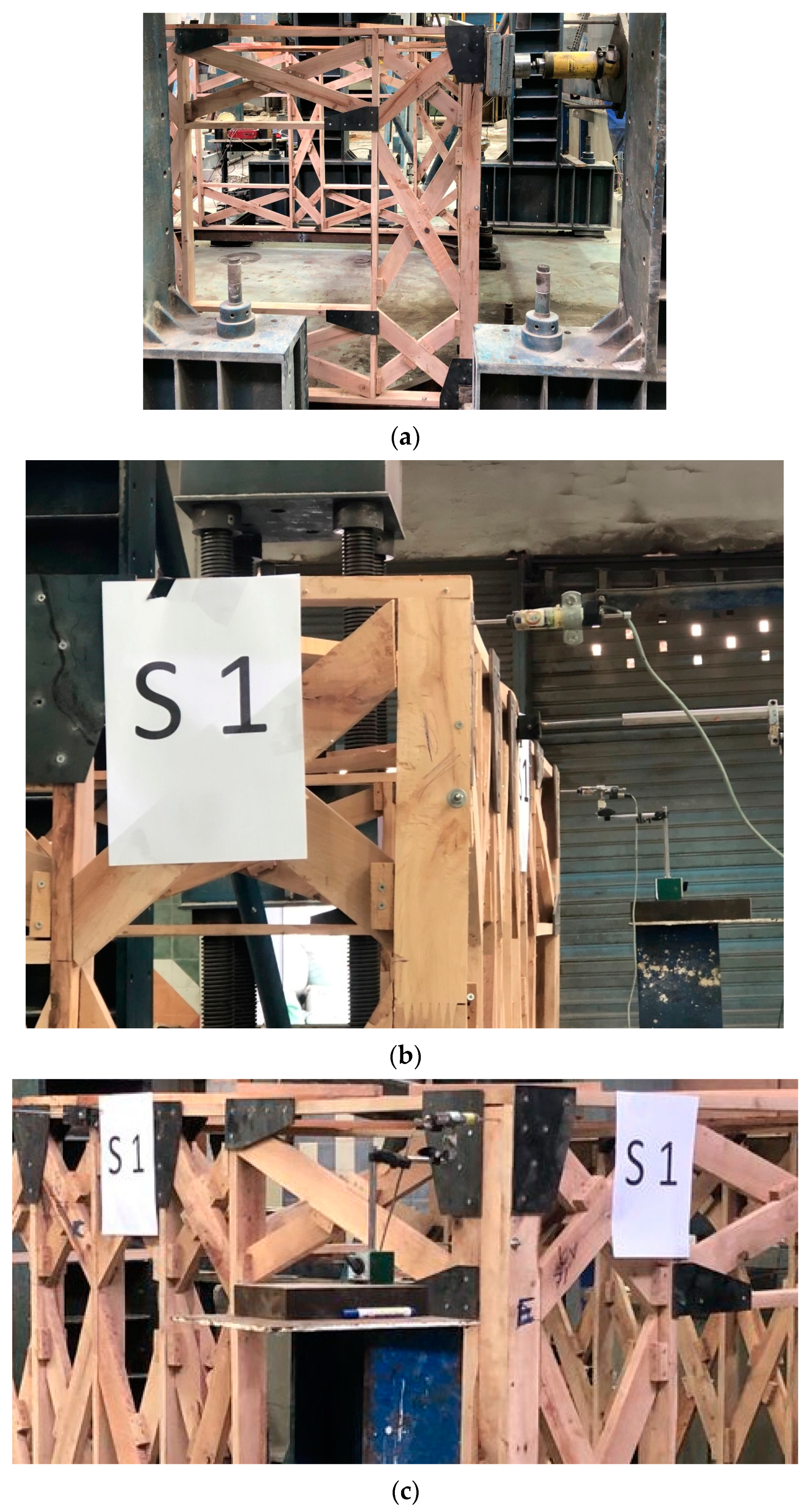
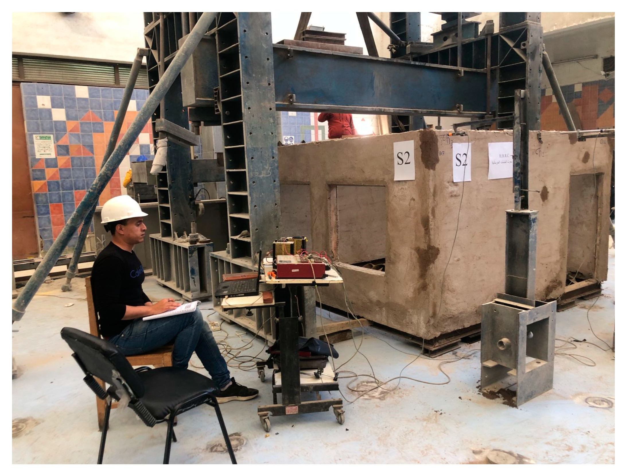
2.4. Structural Testing

The structural testing had two stages within this research. The first stage involved testing the finger-jointed connections between the wooden members under bending. This is necessary as the Glauca wood cannot come in lengths exceeding 1.5 m, hence necessitating joining the different members forming a beam or a stud using finger-jointing. Furthermore, the bending strength of the finger-jointed member needs to be tested to compare it to the bending strength reported by [16] to know whether the design needs to be adjusted accordingly or not. Six finger-jointed samples were tested under the 4-point bending test; three samples were finger-jointed using the polyvinyl acetate (PVA) binder, while the other three samples were finger-jointed using the animal gelatin binder.
The second stage of testing involved constructing a half-scale squared room with a dimension of 2.61 m × 2.61 m, as shown in Figure 3. The model also included the door and window openings as shown in Figure 4. The model also included the wooden ring beam on which the dome is to be supported, as shown in Figure 5. Two specimens were tested under lateral pushover load. The first specimen was the wooden elements only without any of the earth-based mixtures applied, while the second specimen was tested after applying an earth-based mixture as an infill layer in between the wooden members and inner and outer earth-based plaster layers. The choice of the half-scale model was a trade-off choice as the size of the experimentation facility at hand would never allow full-scale testing, while having a quarter-scale or even a one third-scale model would reduce the accuracy of the results due to the connections and the earth-based mixtures both being highly sensitive to scaling. Hence, the half-scale model was the best possible alternative, taking into account that the two tested specimens are actually compared to each other and not to the full-scale structure, negating any side-effects of scaling when comparing the two samples to each other.
This process was repeated twice. The first specimen (S1) was used without the earth-based mixtures used in the infill and plastering of the walls, as shown in Figure 6. For the second specimen (S2), the infill earth-based mixture and the plastering were both applied as shown in Figure 7. The results of both tests were compared to assess the contribution of the infill layer and the plastering on the lateral stiffness of the HWS system.
Figure 6. Specimen S1 (the non-infilled specimen) during testing. (a) The actuator during testing the specimen. (b) LVDTs # 1 and 2. (c) LVDT # 3.
Buildings 14 01785 g006
Figure 7. Specimen S2 (the infilled specimen) during testing The scaled structure was tested in the lateral direction in the manner shown in Figure 6a and Figure 8 in the Reinforced Concrete Institute in Housing and Building Research Center (HBRC). The load was applied using an actuator performing a pushover test by a load cell with a capacity of 25 metric tons and a precision of 1%. Horizontal deflections were measured using three linear variable differential transformers (LVDTs) with a 0.01 mm precision. Two LVDTs were assembled in the direction parallel to the load; the third was placed in the perpendicular direction to account for any lateral deflection due to twisting effect as shown in Figure 6 and Figure 8.
Buildings 14 01785 g007
Figure 8. The experimental setup.
Buildings 14 01785 g008

3. Results

3.1. Results of Carbon Emissions Comparison

Based on the calculation performed during the quantity take-off, 13 m3 of Glauca wood were used in the HWS skeleton. The members were connected by steel connectors weighing roughly 517 kg. The values of CO2 emissions per kg of steel and cubic meter of wood mentioned in Section 2.2 were multiplied by the weight of steel connections and the volume of wood respectively. These two numbers were added together to obtain the total CO2 emissions. The CO2 emissions per square meter were calculated by dividing the total CO2 emissions of the HWS building by its area. The calculated CO2 emissions for the control RC structure were calculated by multiplying the quantities of RC by the CO2 emissions per cubic meter of RC mentioned in Section 2.2, which came to be 0.12 kg of CO2/kg of RC, or 0.3 ton of CO2/m3 of RC.
Table 2 summarizes the results of the calculation and comparison of the total CO2 emissions of each system and the total CO2 emissions per square meter. The results reveal that the CO2 emissions of the HWS are 79% lower than those of its RC counterpart, showing a sizable reduction in carbon emissions. This can be attributed to the high contribution of cement to carbon emissions as shown in Figure 9, in which it is apparent that out of the 17.1 tons of CO2 emitted by the RC skeleton alone, 76% has been emitted by the cement within the concrete mixture. This is one of the main reasons for the low carbon emissions in the HWS system as the cement which is the main contributor to carbon emissions in the RC counterpart is absent in the case of the HWS.

3.2. Results of Cost Comparison

Table 3 summarizes the results of the calculation and comparison of the total superstructure cost of each system and corresponding total cost per square meter, which were based on the unit costs specified in Section 2.3 and the quantities utilized as calculated from the quantity take-off process mentioned in Section 3.1. The results reveal that the HWS costs are 30% less than those of the reinforced concrete equivalent, demonstrating considerable cost savings. As mentioned previously, the calculated costs are the direct costs including material, labor, and equipment costs, not including any long-term costs. Hence, the calculated cost savings are the savings in direct short-term costs and do not include the long-term cost savings from saving energy consumed by HVAC processes. Furthermore, and knowing that these costs were calculated before the March 2024 Egyptian currency devaluation, even these short-term cost savings are expected to increase with time as further currency devaluation is expected to happen in Egypt, which will further increase the prices of the imported components used within RC structures, hence making HWS a more cost-effective alternative. Meanwhile, when examining the major cost contributor to the high cost of the RC alternative, which is the reinforced concrete itself, it can be noted that, as seen in Figure 10, the highest cost share is that of the reinforcing steel itself. That cost share is even expected to further increase as the price of steel is on the rise in several nations, including Egypt. That adds more value to the HWS alternative as the use of steel within this alternative is only limited to the connections.

3.3. Results of Structural Testing

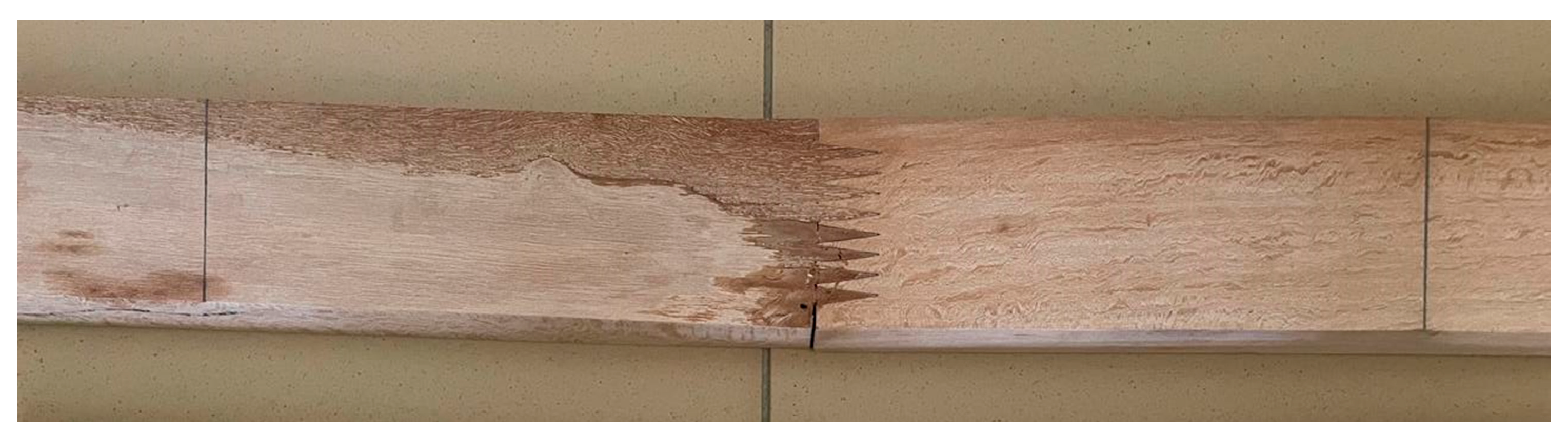
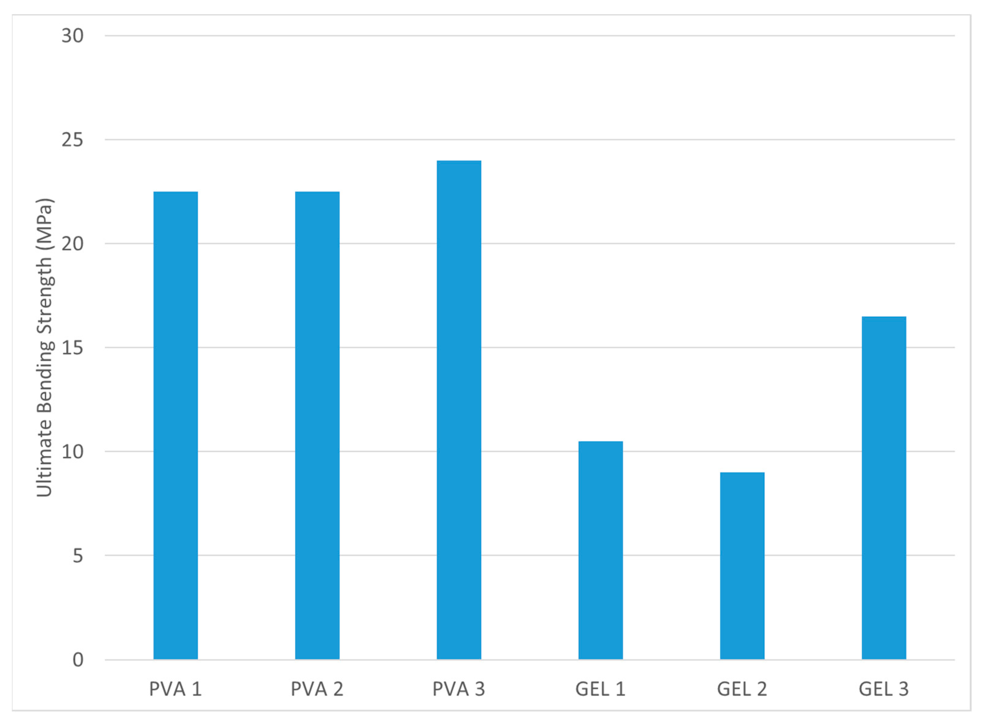
3.3.1. Results of the Finger-Joint Testing

The four-point bending test was applied on the six tested samples by having Casuarina Glauca beam samples, each 1 m long with a cross-section of 100 mm × 40 mm supported on two supports, distanced at 600 mm while the load is gradually applied at two points of loading distanced at 200 mm covering the middle third of the sample with the finger-jointing located at the mid-point of each specimen as shown in Figure 11.
The bending strength of the tested specimen is shown in Figure 12. The values of strength achieved by the specimens incorporating PVA as a binder were all larger than their counterparts incorporating the gelatin binder. However, none of these strengths exceeded 25 MPa, while the bending strength of the non-jointed specimen tested by [16] had an average bending strength of 62 MPa. Accordingly, a decision was made to avoid using finger joints at any point involving bending moments of significant values. The design was detailed in a manner that guaranteed that finger joints were located at points of zero bending moments to avoid any failures within these joints.

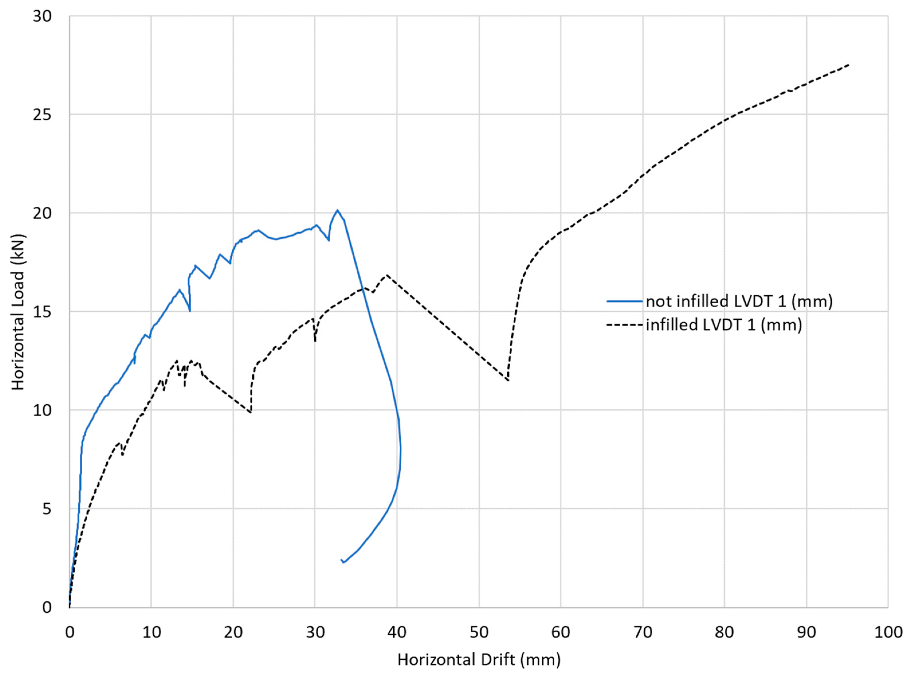
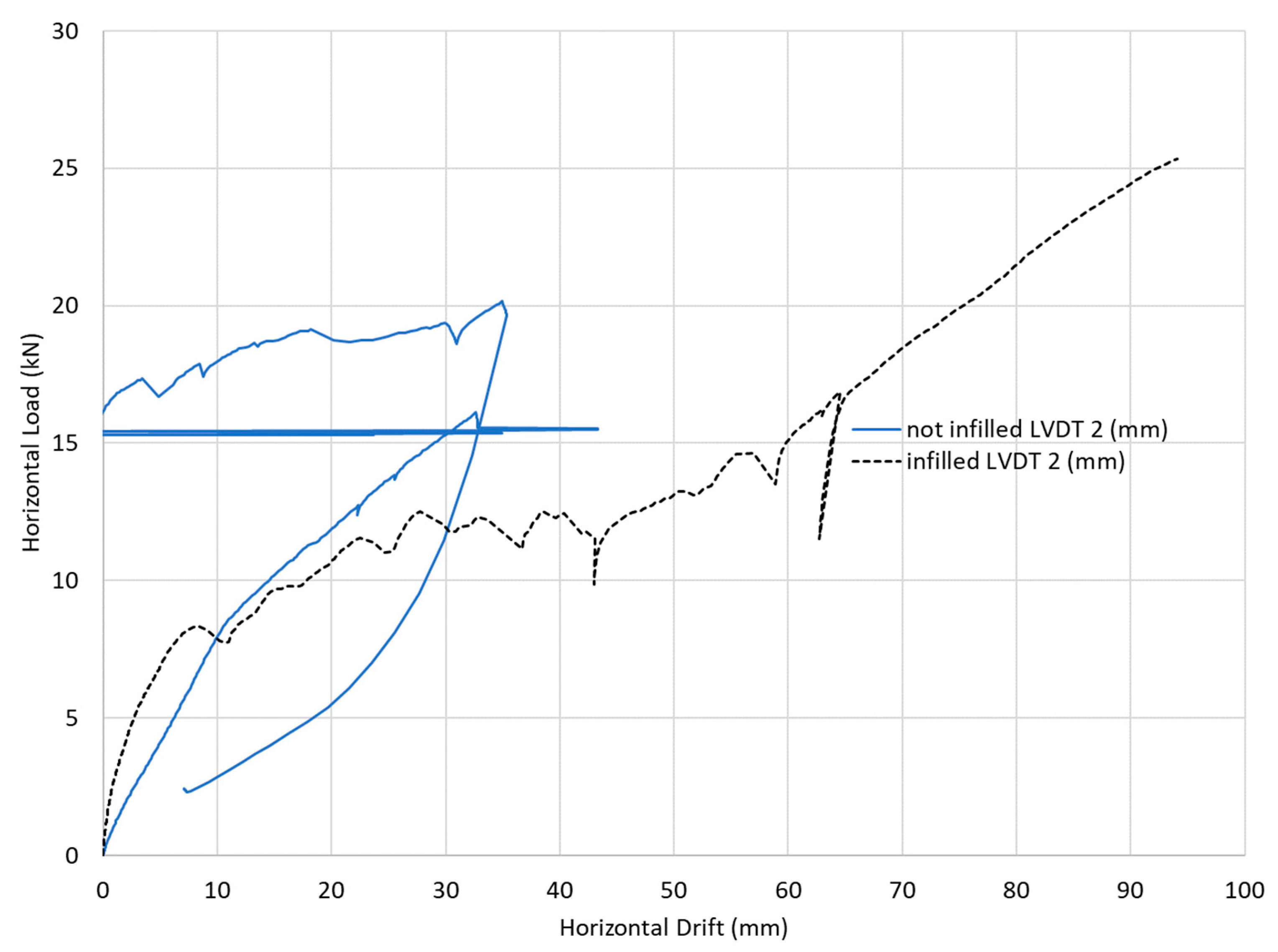
3.3.2. Results of the Scaled Model Testing

The scaled structure was tested in the lateral direction by two specimens, once without the earth-based mixtures used in the infill and plastering of the walls (S1) and the other specimens (S2) by applying the infill earth-based mixture and the plastering. The deflection in the direction parallel to the load is measured by LVDT # 1 and LVDT # 2. Accordingly, the deflection measured by LVDT # 1 is used to plot the load-deflection curves of both tests shown in Figure 13. Meanwhile, the deflection measured by LVDT # 2 is used to plot the load-deflection curves of both tests, as shown in Figure 14.
When comparing the behavior of each structure under lateral loading, it could be seen from the load horizontal deflection curves that the infilled and plastered sample (S2) endured a higher lateral load and experienced a larger lateral drift when compared to the sample with wooden members only without any infill or plastering (S1). The maximum load withstood by the infilled sample (S2) was 27 kN, while that withstood by its non-infilled counterpart (S1) was 20 kN, with a 35% increase in the lateral force withstood by the sample. Meanwhile, the maximum lateral drift experienced by the infilled sample (S2) was 95 mm, while that experienced by its non-infilled counterpart (S1) was 40 mm. This reflects both a higher capacity and a larger ductility, showing a more plastic behavior. This can be also seen when comparing the areas beneath each of the load-deflection curves shown in Figure 13 and Figure 14 as the area beneath the load-deflection curve of the infilled sample (S2) is significantly larger than the area beneath the load-deflection curve of its non-infilled counterpart (S1), reflecting a significant difference in toughness between the two samples. This can be attributed to the infill layer and/or the plastering layer absorbing significant energy before failure, hence making the system tougher. All these facts show that the assumption of the wooden members acting as the sole contributor to the structural strength of the specimen is a conservative assumption leading to an over-designed structure, at least when it comes to its capacity in the lateral direction.
Meanwhile, it could be noticed that the maximum loads and deflections measured by the two LVDTs in the direction parallel to the load are very near to each other. The minor differences between them are mainly due to the lack of perfect symmetry due to the openings in two sides perpendicular to each other, as shown in Figure 3, causing partial loss of symmetry. Hence, the deflections recorded from LVDT # 3, which is perpendicular to the direction of loading, were plotted in Figure 15. These deflections represent the degree of twisting that happened during loading. It could be well noticed that the infilled specimen had significantly lower deflections in that direction when compared to the non-infilled specimen. This can be due to the effect of the earth-based mixture increasing the stiffness significantly to the extent that even the rotational stiffness about the vertical axis has significantly increased due to the presence of the earth-based infill reducing the twist significantly, as shown in Figure 15.
On the other hand, the loads withstood by the non-infilled sample are more than double those of the design lateral wind load, while the loads withstood by the infilled sample are more than triple the value of the design load, as shown in Figure 16.
This is in agreement with the results presented by [15] as the structure also withstood more than its design loads in that case too. This could also be attributed to the significant strength of the Casuarina Glauca wood that caused the wooden members not to fail, which is also similar to what was reported by [13,15], where the members did not fail, while the failures happened in the connections at levels of loading higher than the design loads as the connections are weaker than the wooden members, which is very similar to the behavior reported by [15].
Meanwhile, Figure 17 and Figure 18 show the cracking pattern during and at the end of the testing process of the infilled specimen. It is worth noting that although the cracking pattern has significantly increased towards the end of the testing process, the failure was not considered to be catastrophic in terms of being sudden or being a total collapse. On the contrary, the failed structure shown in Figure 18 is still standing, which means that most of the energy was absorbed by the infill and/or the plastering layer. On the other hand, the abrupt changes apparent in the load-deflection curve of this specimen, shown in Figure 13, could be attributed to the different stages of cracking that the specimen has experienced before failure.

4. Discussion

When examining the breakdown of the CO2 emissions shown in Table 2, it can be noticed that the largest contributor to the difference in CO2 emissions is the wall and plaster as the emissions from the earth-based mixtures used in wall and plaster within the HWS are negligible due to the fact that these are mainly natural materials causing no emissions in their production processes. On the other hand, the walls within an RC skeletal system are made from cement bricks/blocks causing significant emissions during their manufacturing due to the high cement content, and even if replaced by vitrified clay bricks, they will be still emitting significant carbon emissions due to the high energy consumption during the manufacturing process of vitrified clay bricks. Meanwhile, although the carbon emissions due to the HWS skeleton are significantly less than those caused by the RC skeleton, the emissions caused by the HWS can be even further dropped if the wood dehumidification process is guaranteed to be emitting zero carbon emissions. This can be reached by either using air drying, which is time-consuming, or by using the quicklime burial method specified by [22]. Furthermore, one of the main reasons for the HWS being eco-friendlier than its RC counterpart is the fact that it contains no cement as the cement was found to be the highest contributor to the carbon emissions in the RC structural elements with a share of 76% of these emissions, which is mainly due to the high carbon emissions per kg of cement and the high cement content within the concrete mixture. This can even provide further insight into the reason behind the construction industry being one of the most polluting industries in the world, as previously reported by [3], which is mainly due to the excessive use of reinforced concrete globally, even in cases of low-rise buildings which do not necessarily need RC as in the case at hand.
On the other hand, when examining the breakdown of the costs shown in Table 3, it can be noticed that the largest contributor to the difference in costs is the structural skeleton, as the major cost contributor in the RC system is the cost of the steel reinforcement, which is highly affected by the currency devaluation due to the reinforcing steel being either imported or locally manufactured while consuming high energy during the manufacturing process, causing the prices of steel to keep on increasing. Meanwhile, limiting the usage of steel within the HWS skeleton to only steel connections reduces this cost component considering that the type of wood used is from locally farmed trees, which are even farmed on wastewater, causing the cost of such wood to be the lowest of all kinds of woods available in the Egyptian market despite its significant strength. In addition to that, the high strength of the Casuarina wood enabled the researchers to design smaller cross-sections of this wood, additionally saving in the quantities of wood used within the structure. Furthermore, one of the components contributing to the costs within the HWS skeleton is the cost of drying wood using the conventionally used kiln-drying method, which consumes high energy, causing significant cost increases. Hence, one of the routes to further reduce the cost of the HWS skeleton would be to utilize more cost-effective wood dehumidification methods, such as burial within the quicklime method specified by [22].
Meanwhile, although the cost of wall and plaster in the HWS system is less than that used with the RC counterpart, this cost component within the HWS system could have been further reduced if the site was not in the desert oasis of Siwa that has no clay or silt, which causes the costs to increase due to transporting these materials from the Nile valley to Siwa. That means that this cost component can be further reduced in future projects nearer to sources of silt or clay. Hence, the 30% cost savings experienced by using HWS rather than RC can be further increased in the future.
Furthermore, when digging deeper into the cost components of the RC skeleton itself, the highest contribution to cost comes from the steel itself, with a share of 45% of the cost of the reinforced concrete skeleton total cost and even 75% of the material costs within the RC skeleton. This is one of the main reasons for the HWS being more cost-effective as it involves minimizing the usage of steel to be only within connections of the wooden members, which can be even further enhanced if the connections were to be designed using another material, such as wood–plastic composites, as studied by [14]
Meanwhile, the structural performance of the tested specimen showed that the constructed wooden structure was of a lateral capacity about four times what it was originally designed for. This could be attributed to several conservative design assumptions that were made during the structural design process. One design assumption that was made and found to be conservative is the strength of the Casuarina Glauca wood that was taken to be two standard deviations less than the mean value reported by [16], as not a single wooden member has failed within the structural testing processes and all the failures happened in the connections. It was even noticed that after dismantling the failed structural specimens, the dismantled wooden members were not permanently deformed, which means that all the deformations these members faced were within the linear elastic portion of their stress–strain relations. Another design assumption found to be conservative was that the steel connections are not rigid in terms of transferring moments between the different members of the structure. That assumption was proven to be conservative as these connections had rotational stiffnesses apparently experienced when examining the failure patterns of the two structures tested.
A third design assumption found to be conservative is totally neglecting any structural strength of the earth-based mixtures applied, whether as an infill between the walls or as a plastering layer, as the infilled sample withstood a load about 27% larger than its non-infilled counterpart. That was even clearer when measuring the deflection perpendicular to the load representing the twisting effect. The twist measured from the infilled specimen was negligible, showing a significant increase in stiffness even when examining the rotational stiffness about the vertical axis. A conservative assumption as such is typically made when designing RC skeletons as the relative stiffness of the RC skeleton when compared to a masonry wall is large; however, the situation was found to be different when it comes to the stiffness of the wooden skeleton within the HWS versus the stiffness of the earth-based mixtures used within the HWS. However, another parameter can come into the picture, which is the content of the earth-based mixtures that can vary its contribution to the overall stiffness of the HWS system. Hence, and as these earth-based mixtures vary from one case to another depending on the availability of the different types of soils, this conservative assumption could be still for sufficient reasons.

5. Conclusions and Recommendations

5.1. Conclusions

Based on the study performed, the following conclusions can be drawn:
  • Casuarina glauca wood demonstrated its suitability as an inexpensive and environmentally friendly building material for straightforward construction within the HWS system;
  • The HWS system has been shown to be more environmentally friendly, producing about one fifth of the CO2 emissions produced by its RC counterpart;
  • The HWS system has been shown to be more affordable, with a reduction in direct short-term costs of about 30% when compared to the costs of its RC counterpart;
  • The finger-jointing process could not achieve the same bending strengths of the non-jointed specimen; hence, it cannot be depended on when it comes to the design of sections subject to significant bending moments as the moment capacity at the locations of the finger-joints was significantly lower than those of non-jointed members, proving that it needs further enhancement. Accordingly, finger-jointing was limited to only locations with negligible or zero bending moments;
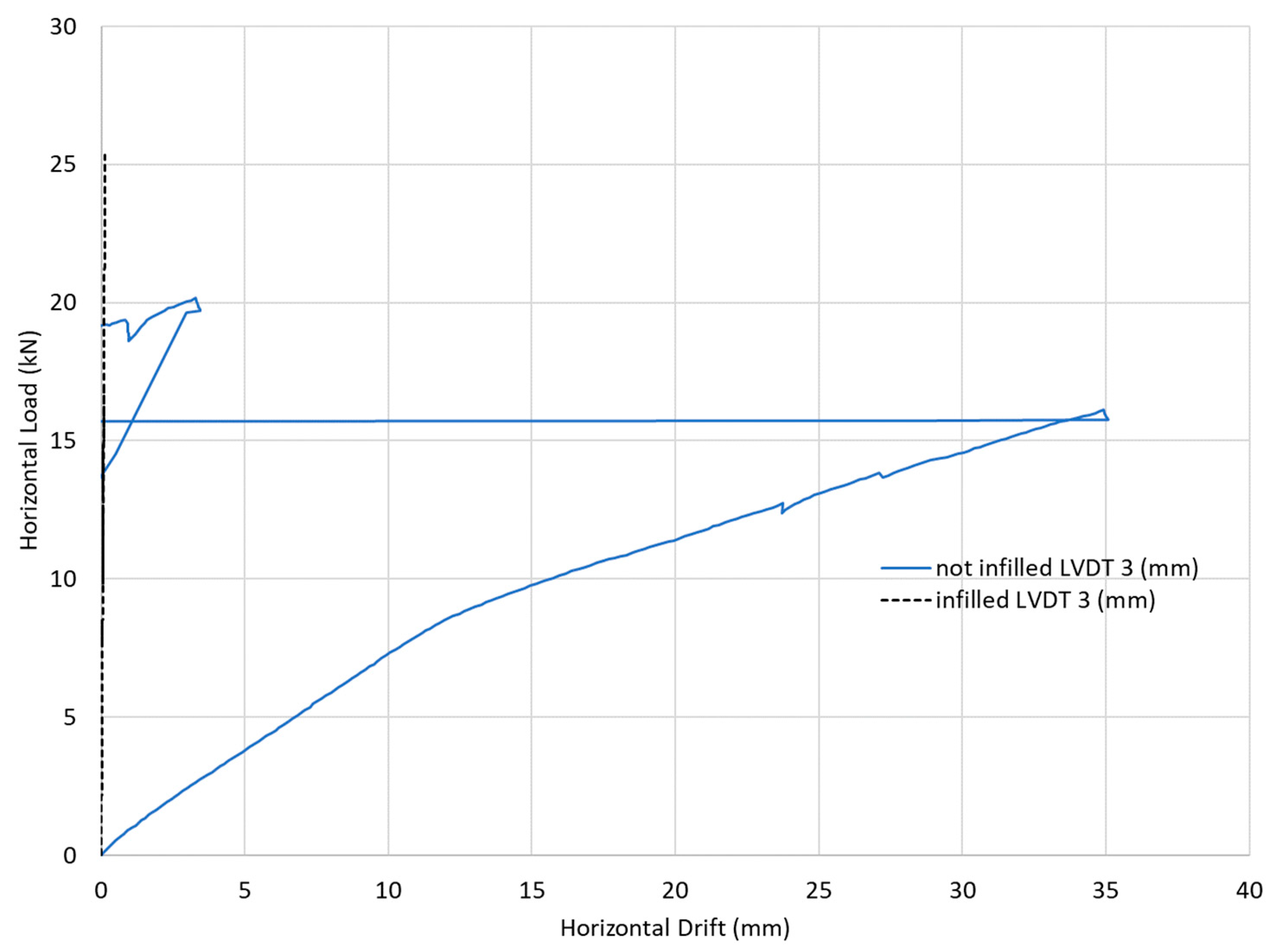
  • The infill layer together with the plastering layer increases the ductility of the HWS in the lateral direction compared to that of the non-infilled sample by more than 125%;
  • The infill layer together with the plastering layer increases the lateral capacity of the HWS by about 27%;
  • The infill layer together with the plastering layer increases the toughness of the system when compared to the non-infilled sample by even more than double;
  • The infill layer together with the plastering layer decreases the twisting within the HWS system to be nearly negligible;
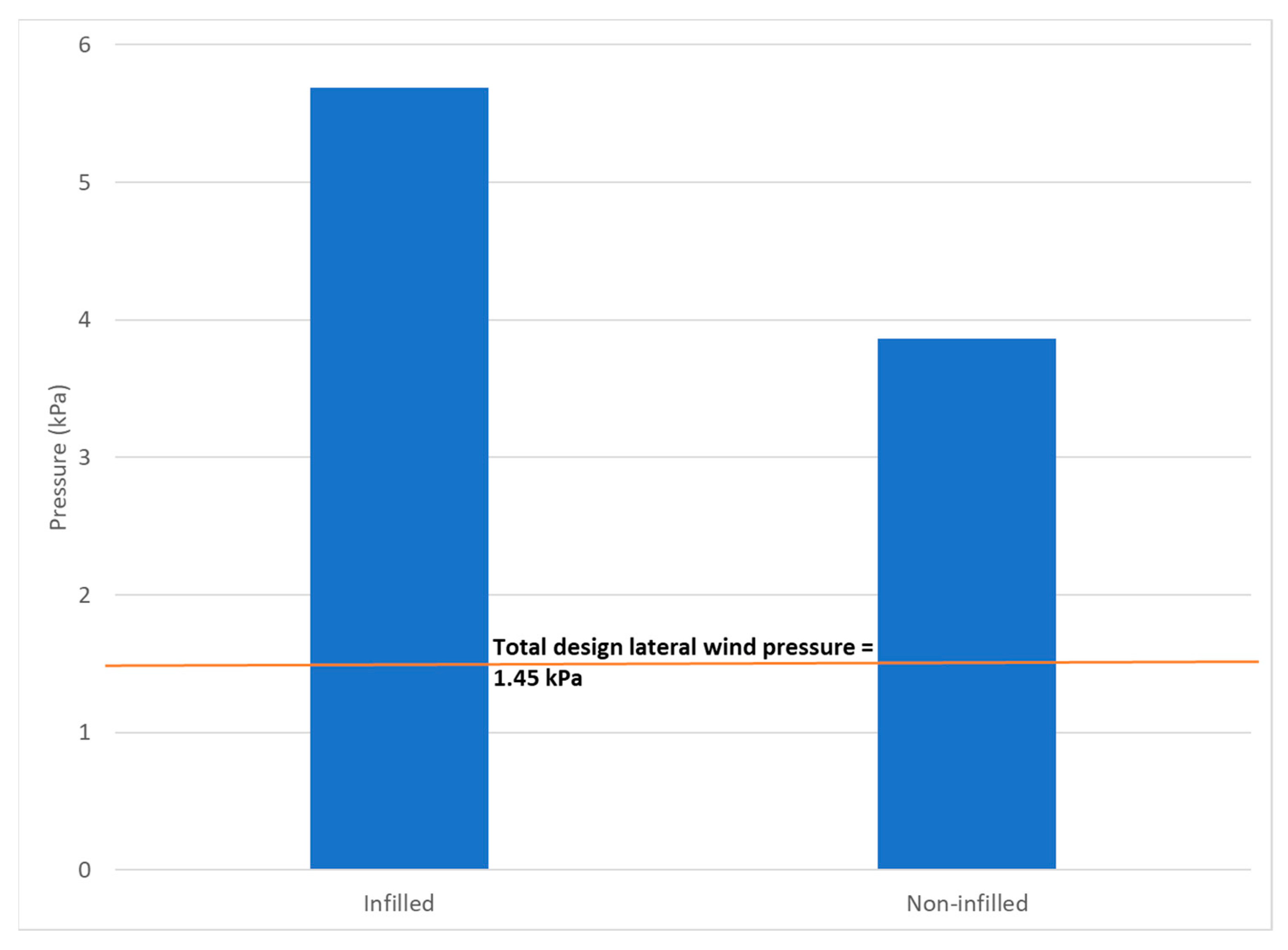
  • The initial design assumption that the infill layer together with the plastering layer are of negligible strength in comparison to the wooden skeleton is not accurate enough and needs to be re-examined as it leads to an over-designed structure.

5.2. Recommendations

Based on of the study performed, the following are recommended:
  • It is advised that a thorough analysis identical to the one at hand be carried out using wood dehumidified by burial in calcium oxide while keeping track of the prices and precisely estimating the CO2 emissions;
  • To precisely track the full-scale costs and CO2 emissions linked to a full-scale prototype, it is advised that the research undertaken within this study be performed on a larger-scale construction on an industrial scale;
  • It is recommended that a long-term study be conducted to assess the thermal performance of the HWS system in comparison to the RC system over time. This comparison is vital as the short-term and long-term costs of having HVAC systems within each of the two studied alternatives are expected to be different due to the difference in thermal properties;
  • Perform a separate parametric study covering the different parameters related to the finger-jointing process to increase the bending strength of the finger-jointed members;
  • Further study different samples with infill soil only without the plastering layer to determine which of them is responsible for the increase in the ductility, strength, and toughness of the system;
  • Further study the effects of changing the different mixtures of the infill soil and plastering layer on the behavior of the system under lateral loading.

Author Contributions

Conceptualization, T.H., M.D., and M.A.; methodology, H.A., M.D., and K.Y.; software, M.D., H.A., and T.H.; validation, H.A.; formal analysis, M.D. and H.A.; investigation, M.D.; resources, M.A. and K.Y.; data curation, H.A.; writing—original draft preparation, M.D.; writing—review and editing, H.A., K.Y., and T.H.; visualization, T.H.; supervision, H.A.; project administration, K.Y.; funding acquisition, M.A. All authors have read and agreed to the published version of the manuscript.

Funding

This research received no external funding.

Data Availability Statement

The raw data supporting the conclusions of this article will be made available by the authors on request.

Acknowledgments

The authors would like to acknowledge the American University in Cairo for covering the publication fees.

Conflicts of Interest

Author Mohamed Adham was employed by the company Arabia Contracting Inc. Author Tamer Hassan was employed by the company ALDAR Engineering. The remaining authors declare that the research was conducted in the absence of any commercial or financial relationships that could be construed as a potential conflict of interest.

References

  1. Abdellatif, N.; Darwish, M.; Nassar, K.; Youssef, P.; Dardir, A.; Ahmed, A.; Eltamimy, M.; Mamdouh, M.; Abdelazim, R. Manufacturing and Mechanical Testing of Casuarina Glauca Blockboards. In Sustainable Issues in Infrastructure Engineering. Sustainable Civil Infrastructures; Springer: Cham, Switzerland, 2020; pp. 14–22. [Google Scholar]
  2. Shen, W.; Shen, W.; Cao, L.; Li, Q.; Li, Q.; Zhang, W.; Wang, G.; Wang, G.; Li, C. Quantifying CO2 emissions from China’s cement industry. Renew. Sustain. Energy Rev. 2015, 50, 1004–1012. [Google Scholar] [CrossRef]
  3. Blasing, T.J.; Hand, K. Monthly carbon emissions from natural-gas flaring and cement manufacture in the United States. Tellus B 2007, 59, 15–21. [Google Scholar] [CrossRef]
  4. Jeong, S. System dynamics approach for the impacts of FINEX technology and carbon taxes on steel demand: Case study of the POSCO. Int. J. Precis. Eng. Manuf. Green Technol. 2015, 2, 85–93. [Google Scholar] [CrossRef]
  5. UNHABITAT. Informal Settlements in the Arab Region; UNHABITAT: Giza, Egypt, 2020. [Google Scholar]
  6. Farouk, M.A. Cautious Hopes for Slum Dwellers Relocated in Egypt Housing Project; Reuters: London, UK, 2020. [Google Scholar]
  7. UN-HABITAT. The Housing Crisis—UN-Habitat. 12 September 2005. Available online: https://unhabitat.org/wp-content/uploads/2005/11/GRHS05F2.pdf (accessed on 11 November 2023).
  8. Hassanein, A.A.; Khalil, B.N. Building Egypt 1—A general indicator cost index for the Egyptian construction industry. Eng. Constr. Archit. Manag. 2006, 13, 463–480. [Google Scholar] [CrossRef]
  9. Trading Economics. Egypt—Rural Population. 26 September 2018. Available online: https://tradingeconomics.com/egypt/rural-population-percent-of-total-population-wb-data.html (accessed on 26 September 2018).
  10. Balila, A. Enhancing Strength and Durability of Adobe Bricks by Introducing Bio-Inspired Stabilisers. 2017. Available online: https://ethos.bl.uk/orderdetails.do?uin=uk.bl.ethos.749336 (accessed on 4 December 2023).
  11. Darwish, M.; Khedr, S.; Halim, F.; Khalil, R. Novel Simplified Construction of Walls and Prisms Made of CEBs and Earth-Based Mortar. ASCE Pract. Period. Struct. Des. Constr. 2020, 25, 04020041. [Google Scholar] [CrossRef]
  12. Jaquin, P.; Augarde, C.E.; Legrand, L. Unsaturated Characteristics of Rammed Earth. 2008. Available online: https://core.ac.uk/display/264450 (accessed on 4 December 2023).
  13. Hussein, M.; Darwish, M.; Nassar, K. Design and Characteristics of a Novel Casuarina Glauca Wooden K-Truss Formwork. ASCE Pract. Period. Struct. Des. Constr. 2022, 27, 04022020. [Google Scholar] [CrossRef]
  14. Mahmoud, A.; Said, J.; Bader, S.; Sayed, M.; Fayez, M.; Yacoub, O.; Youssef, P.; Darwish, M.; Nassar, K.; Sayed-Ahmed, E.; et al. Design and testing of Pre-engineered Prefabricated Casuarina Wooden Truss. In Proceedings of the Seventh International Conference on Structural Engineering, Mechanics and Computation (SEMC 2019), Cape Town, South Africa, 2–4 September 2019. [Google Scholar]
  15. Allam, H.; Yosry, K.; Adham, M.; Darwish, M.; Nassar, K. Design and Characteristics of a Hybrid Wood-Soil System Made from Casuarina glauca Wood. Sustainability 2023, 15, 3579. [Google Scholar] [CrossRef]
  16. Hussein, M.; Nassar, K.; Darwish, M. Mechanical Properties of Egyptian Casuarina Wood. J. Mater. Civ. Eng. 2019, 31, 04019293. [Google Scholar] [CrossRef]
  17. Hussein, M.; Darwish, M.; Nassar, K. The effect of moisture content on some mechanical properties of Casuarina wood. In Proceedings of the Seventh International Conference on Structural Engineering, Mechanics and Computation (SEMC 2019), Cape Town, South Africa, 2–4 September 2019. [Google Scholar]
  18. Anselm, A.J. Earth Shelters; A Review of Energy Conservation Properties in Earth Sheltered Housing. 2012. Available online: https://intechopen.com/books/energy-conservation/earth-shelters-a-review-of-energy-conservation-properties-in-earth-sheltered-housing (accessed on 2 January 2023).
  19. ECP 201-2012; Egyptian Code for Loads. Housing and Building Research Center: Cairo, Egypt, 2012.
  20. O86-14; Engineering Design in Wood. Canadian Standards Association Group: Mississauga, ON, Canada, 2014.
  21. Hertz, K.D.; Halding, P.S. CO2 Emissions from Building Lifecycles; Technical University of Denmark, Department of Civil Engineering: Kongens Lyngby, Denmark, 2020. [Google Scholar]
  22. Darwish, M.; Azer, R.; Azmy, A.; Hegazy, A.; Elleissy, S.; Ahmed, A.; Morsi, A.; Nassar, K.; Youssef, P. New Technology for Drying Wood using Quicklime. In Proceedings of the Canadian Society of Civil Engineers Materials Speciality Conference; Springer: Berlin/Heidelberg, Germany, 2021. [Google Scholar]
Figure 1. Structural system of the designed nursery, including domes (with wooden ring beams), vaults, and a skylight supported on HWS walls.
Buildings 14 01785 g001
Figure 2. Typical connection details.
Buildings 14 01785 g002
Figure 3. Plan of the half-scale model tested in the structural lab with the dimensions in meters.
Buildings 14 01785 g003
Figure 4. Section elevation (1-1) of the half-scale model.
Buildings 14 01785 g004
Figure 5. Diagonal section (2-2) of the half-scale model.
Buildings 14 01785 g005
Figure 9. Contribution of steel and cement to the carbon emissions within the RC alternative, showing the amounts of emissions caused by each in kgCO2 and its percentage to the emissions within the RC skeleton.
Buildings 14 01785 g009
Figure 10. The different cost components in Egyptian pounds constituting the cost of the RC skeleton in the building together with the percentage of each.
Buildings 14 01785 g010
Figure 11. Finger-jointed specimen.
Buildings 14 01785 g011
Figure 12. Ultimate bending strength of the tested finger-jointed specimen.
Buildings 14 01785 g012
Figure 13. Load-deflection curves for the two tested specimens as measured from LVDT # 1.
Buildings 14 01785 g013
Figure 14. Load-deflection curves for the two tested specimens as measured from LVDT # 2.
Buildings 14 01785 g014
Figure 15. Load-deflection curves for the two tested specimens as measured from LVDT # 3.
Buildings 14 01785 g015
Figure 16. Comparison of the equivalent lateral wind pressure withstood by the specimen versus the design lateral wind pressure.
Buildings 14 01785 g016
Figure 17. Cracks initiated during testing the infilled specimen.
Buildings 14 01785 g017
Figure 18. The infilled specimen at the end of the test.
Buildings 14 01785 g018
Table 1. The CO2 emissions per unit of the materials used acquired from [15,18,21].
ItemCO2 Emissions per Unit
Steel1 kg of CO2/kg
Cement0.9 kg of CO2/kg
Wood0.35 kg of CO2/kg
Earth-based mixture0
Table 2. The CO2 emissions (in tons of CO2) for the HWS and RC systems.
ItemHWSRC
Skeleton7.1517.51
Connections0.52
Wall and plaster0.0019.80
Total CO2 emissions (tons)7.6737.31
Total CO2 emissions per unit area (t/m2)0.030.14
Table 3. The costs for the HWS and RC systems.
ItemHWSRC
Costs of structural skeleton (EGP)416,000624,056
Costs of wall and plaster (EGP)193,565244,400
Total cost (EGP)609,565868,456
Total cost (USD)19,04927,139
Total cost per unit area (USD/m2)71.79102.28
Disclaimer/Publisher’s Note: The statements, opinions and data contained in all publications are solely those of the individual author(s) and contributor(s) and not of MDPI and/or the editor(s). MDPI and/or the editor(s) disclaim responsibility for any injury to people or property resulting from any ideas, methods, instructions or products referred to in the content.

