Article

Study on the Vibration Isolation Performance of Sliding–Rolling Friction Composite Vibration Isolation Bearing

1
School of Civil Architectural Engineering, North China University of Science and Technology, Tangshan 063000, China
2
School of Civil Engineering, Tangshan University, Tangshan 063000, China
*
Author to whom correspondence should be addressed.
Buildings 2024, 14(7), 2053; https://doi.org/10.3390/buildings14072053
Submission received: 9 May 2024 / Revised: 11 June 2024 / Accepted: 3 July 2024 / Published: 5 July 2024

Abstract

:
This study focuses on investigating the newly proposed sliding–rolling friction composite seismic isolation bearing. It begins by establishing the dynamic equilibrium equation for the structure. Subsequently, this paper proposes a calculation model for the sliding–rolling friction composite seismic isolation bearing, integrating fundamental theories of structural dynamic response analysis and numerical solution methods. Utilizing finite element analysis software ABAQUS (2021), the mechanical properties of the seismic isolation bearing are comprehensively assessed. Through this evaluation, the optimal parameters of the seismic isolation bearing are determined. The findings reveal that the optimal parameters include a friction coefficient (μ) of 0.04, four U-type dampers at 45° angles, a width of 60 mm, five balls, and two shims.

1. Introduction

China, positioned at the convergence of several seismic zones, experiences active crustal movements and frequent earthquakes, notably in regions such as Sichuan, Yunnan, and Inner Mongolia. Consequently, the advancement of seismic isolation technology is imperative to mitigate earthquake-related challenges. Notably, seismic isolation techniques have historical precedents, albeit lacking a comprehensive theoretical framework. For instance, during the construction of the Forbidden City in Beijing, glutinous rice was mixed into the foundation material due to its favorable flexibility and integrity. This incorporation facilitated uniform deformation during earthquakes, yielding favorable seismic effects. Similarly, the Small Wild Goose Pagoda in Xi’an features a tower body and foundation arranged in an arc, exhibiting a “non-tilting” structure akin to contemporary friction pendulum support systems [1].
The formal conceptualization of seismic isolation emerged in 1881 through the work of Kozo Kawai in Japan. Since then, extensive research endeavors have been undertaken worldwide to explore the mechanical properties of seismic isolation bearings through experimentation, numerical simulations, and the application of novel materials. Moreover, the development of new models has been pursued both domestically and internationally [2,3,4,5,6,7].
Seismic isolation bearings represent a crucial component of structural isolation technology, serving to enhance the seismic resilience of building structures. These seismic isolation bearings not only have excellent damping performance, but also have a wide variety of characteristics. Zayas, V.A. et al. [8] analyzed the effect of friction pendulum bearing (FPS) for isolating torsional motions of eccentric and irregular structures in buildings, and the results demonstrated that the reduction in seismic loads can be as much as eight times greater with the correct design. Quaglini, V. et al. [9] analyzed the effect of friction pendulum bearings (FPS) for isolating torsional motions in buildings by changing the pad material or lubrication conditions to provide different equivalent damping ratios for the seismic isolation system. Modifying the coefficient of friction of the bearing by altering the pad material or lubrication conditions yields disparate equivalent damping ratios for the seismic isolation system. Fenz, D.M. et al. [10] validated the theoretical force–displacement relationship by characterizing bearings with sliding surfaces exhibiting the same radius of curvature and coefficient of friction. The outcomes demonstrate that the property is predominantly a rigid bilinear hysteresis, which collapses to a rigid linear hysteresis for equal coefficients of friction.
Composite seismic isolation bearings have been extensively utilized to address the limitations of traditional seismic isolation bearings by amalgamating various seismic isolation materials and techniques, thereby enhancing the seismic isolation performance of structures [11,12]. In this study, a novel sliding–rolling friction composite isolation bearing is introduced, which combines the features of sliding and rolling isolation bearings while incorporating a U-shaped damper for reset. Utilizing ABAQUS software, the mechanical properties of the sliding–rolling friction composite seismic isolation bearing were simulated and analyzed. The optimal parameters of the seismic isolation bearing were identified, offering valuable data references for engineering applications.

2. Establishment of Structural Dynamic Equations

The use of sliding–rolling friction composite isolation bearings for foundation isolation results in two states of relative static and relative motion for the superstructure and foundation under seismic action. The state of relative motion depends on whether the horizontal seismic force on the new composite isolation bearings reaches the critical value. To accurately analyze the actual force situation of the building structure under seismic action, this paper selects the “tandem mass system” model according to the characteristics of structural discretization and vibration models. The model assumes that all the mass of the structure is centrally distributed at the key points where the translational displacements need to be calculated. The total mass at any node is equal to the sum of the masses assigned to that node by the segments connected to it.

2.1. Relative Stationarity

When the seismic action generates a base shear force that is less than the maximum static friction of the bearing, indicated by i = 0 n m i X g ¨ < μ i = 1 i = n m i g , the structure remains relatively stationary. At this point, the maximum static friction of the seismic isolation layer is sufficient to balance the generated shear force. The seismic isolation layer and the superstructure as a whole remain in a seismic state, allowing the structure to dissipate energy. The superstructure’s mass, stiffness, and damping matrices are as follows, and the structural system has n degrees of freedom:
M S = m 1 0 0 m n
K S = k 1 k 1 k 1 k 1 + k 2 k 3 k n k n
C S = a 0 1 n m i + a 1 k 1 a 0 m n a 0 m n   + a 1 k n
Style:
m 1 , m 2 , , m n —Mass at level i of the structural system;
k i —Shear stiffness of structural system layer i.
The Rayleigh damping Equation (4) is as follows
C = a 0 M + a 1 K
where   a 0 , a 1   are solved by (5) and (6) below.
a 0 + a 1 w 1 2 = 2 ξ 1 w 1
a 0 + a 1 w 2 2 = 2 ξ 2 w 2
Style:
a 0 , a 1 —Scale factor;
w 1 , w 2 —First and second modes of vibration of structural systems;
ξ 1 , ξ 2 —First and second damping ratios for structural systems, reinforced concrete structure   ξ 1 = 0.05, ξ 2 = 0.07; Steel structure ξ 1 = 0.02, ξ 2 = 0.03.
Its corresponding equation of motion is:
M S X ¨ + C S X ˙ + K S X = M S I X ¨ g
Style:
X , X ˙ , X ¨ —Lateral displacement, velocity and acceleration vectors for each mass of the superstructure;
X ¨ g —earthquake acceleration vector.

2.2. Relative State of Motion

When the earthquake’s base shear force exceeds the maximum static friction of the bearing, indicated by i = 0 n X ¨ g G m i > μ i = 0 i = n m i g , the structure enters a state of relative sliding. Even after offsetting the maximum static friction of the seismic isolation layer, the shear force remains high, and the seismic isolation bearing and the superstructure work together to dissipate energy.
In this case, the seismic isolation layer is an additional layer in the structural system, which increases the number of degrees of freedom of the seismic isolation structure to n+1. The mass matrix, stiffness matrix, and damping matrix of the seismic isolation structure can be introduced based on the matrix construction of the superstructure.
M G = m 0 0 0 m n
K G = K 0 + k 1 k 1 k 1 k 1 + k 2 k 3   k n k n
C G = C 0 + a 0 1 n m i + a 1 k 1 a 0 m n a 0 m n   + a 1 k n
Style:
m 0 —The total mass of the seismic isolation layer, denoted as m 0 = m s , m s is the mass of a single seismic isolation bearing;
K 0 —The horizontal stiffness of the seismic isolation layer, denoted as K 0 = K s , K s is the horizontal stiffness of a single seismic isolation bearing;
C 0 —The equivalent damping ratio of the seismic isolation layer, denoted as C 0 = 2 m s ω 0 ζ e q , ω 0 is the horizontal stiffness of a single seismic isolation bearing, and ζ e q is the equivalent damping ratio of the seismic isolation layer.
Its corresponding equation of motion is:
M G X ¨ G + C G X G ˙ + K G X G = M G I X ¨ g
Style:
X G , X G ˙ , X ¨ G Lateral displacement, velocity, and acceleration vectors for each mass of the seismically isolated structure;
X ¨ g —Seismic acceleration vectors.

3. ABAQUS Finite Element Analysis of Seismic Isolation Bearings

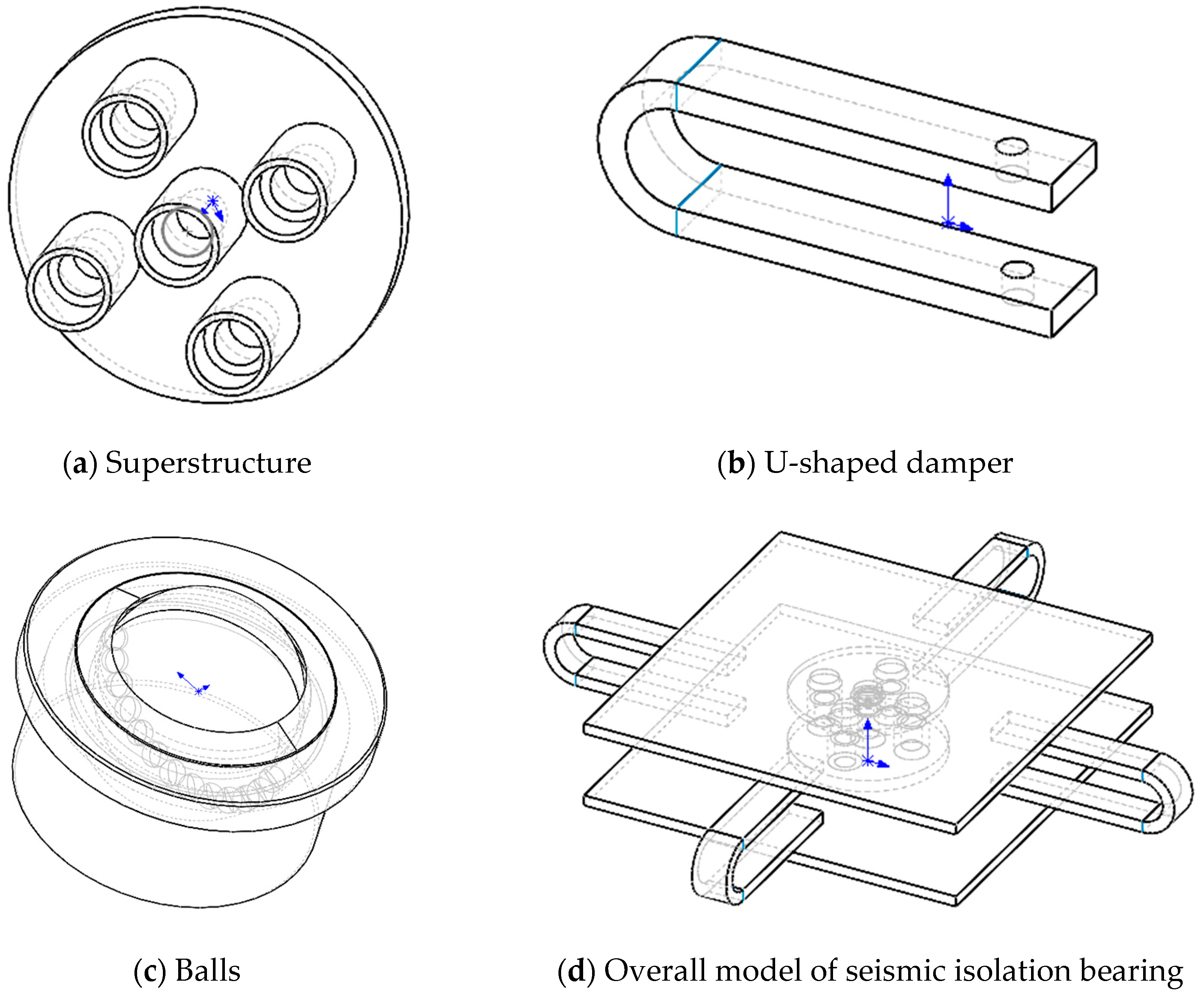
3.1. Support Structure

The sliding–rolling friction composite seismic isolation bearing is composed of a number of components, including upper and lower connection plates, an intermediate column, a spring, a ball, a friction plate, and other components. Additionally, a U-shaped damper is set around the bearing to assist in energy consumption. The connecting plate is connected to the intermediate column, U-shaped damper, and friction plate via bolts, facilitating ease of installation and dismantling. The lower connecting plate is coated with a layer of PTFE, a white wax-like substance with semi-transparency, heat resistance, cold resistance, acid and alkali resistance, insolubility in other solvents, and a low coefficient of friction. This coating provides an ideal lubricating surface for sliding friction. The design of sliding–rolling friction composite seismic isolation bearings is based on the principles of energy dissipation through sliding and rolling friction, as well as the synergistic effect of springs and U-shaped dampers. The spring compression is adjusted by increasing or decreasing the number of shims, and the number of balls in the grooves is changed, thus proportionally distributing the loads applied from the upper part to the sliding surfaces and the ball group. This reduces the seismic transmission to the superstructure through the deformation of energy dissipation.

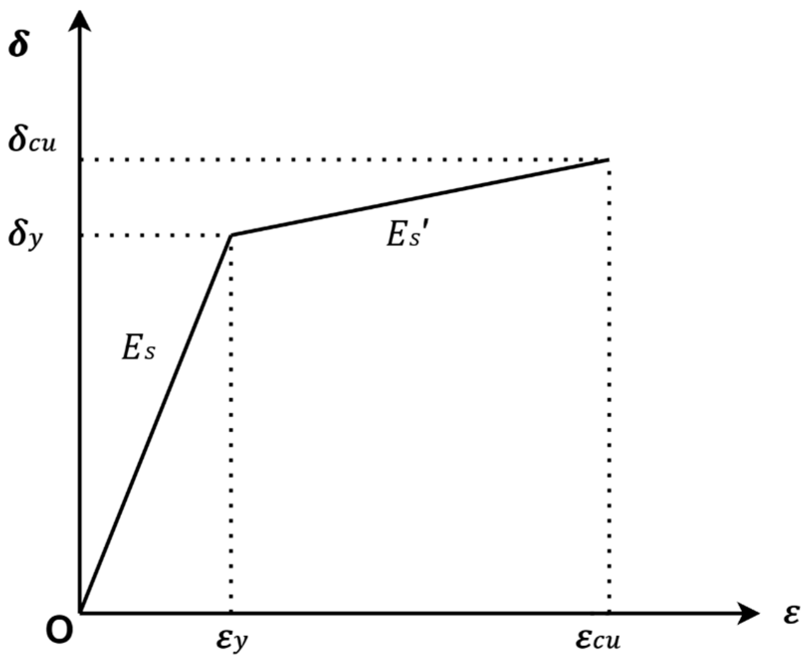
3.2. Material Intrinsic Relationship

The sliding–rolling friction composite seismic isolation bearing consists of upper and lower connecting plates, U-shaped dampers, springs, and ball rollers, all made of steel. The material properties are defined using the bifold principal model for all principal relationships of steel. The stress–strain curves are shown in Figure 1. The decision to use the bifold model, rather than more complex models such as the triple-fold model, is based on several factors. Firstly, the bifold model has been widely applied in engineering and has been practically validated. Additionally, it can succinctly and efficiently describe the stress–strain relationship of steel before and after yielding. Secondly, this model offers high computational efficiency and stability while maintaining computational accuracy [13]. It is suitable for simulating and analyzing sliding–rolling friction composite seismic isolation bearings. The model assumes a constant slope of the stress–strain relationship after yielding, which is expressed by Equation (12).
δ = E s ε s                                                                                                           ε s ε y δ = δ y + E s ( ε s ε y )             ε y < ε s ε c u  
Style:
E s —Modulus of elasticity of steel;
E s —Slope of the hardened section of the steel;
σ y —Yield strength of steel;
ε —Strain in steel;
ε y —Yield strain of steel;
ε c u —The peak strain corresponding to the time when the steel reaches its ultimate tensile strength.
The basic parameters of the various types of materials used in the support are shown in Table 1.

3.3. Model Simplification Processing

During the ABAQUS finite element modeling process, simplification of the physical model is necessary to improve computational efficiency and highlight key features. This simplification aids in mesh delineation and improves computational speed, ultimately facilitating model convergence.
This paper presents a model of a sliding–rolling friction composite seismic isolation bearing, which consists of a superstructure, U-shaped damper, PTFE coating, ball, and friction plate. The connection relationship between the upper connection plate and the intermediate column is simplified using the merge method in a Boolean operation, replacing the complex bolt connection with an overall modeling approach to construct a more simplified superstructure. This simplification improves the calculation speed and enhances the convergence of the model. This paper simplifies the bolted relationship between the U-shaped damper and the support into a binding connection. The main mechanical properties of the U-shaped damper are retained while effectively simplifying the model’s structure and improving analysis efficiency. Figure 2 displays the simplified components and three-dimensional model of the sliding–rolling friction composite seismic isolation bearing.
To assess the effectiveness of the simplified treatment, we compared computational time and convergence. The simplified model significantly reduced the total time required for a full analysis by one-third compared to the pre-simplified model. Additionally, the simplified model showed faster convergence in the iterative solving process, requiring fewer iterations and reducing computation time per iteration.

3.4. Definition of Exposure

This paper meticulously defines and sets parameters for the mechanical behavior of sliding–rolling friction composite seismic isolation bearings. Firstly, the connection relationship between the U-shaped damper and the upper and lower friction plates is considered, whose main functions are fixation and force transmission. To ensure a solid connection between the two and almost no slip in the simulation [14], the binding constraint (Tie) is chosen in this paper. Secondly, the spring regulates the load distribution between the ball and the sliding surface in the seismic isolation bearing. To define the spring connecting the ball and the intermediate column, the Connector Element is used. This not only saves computational resources but also ensures model accuracy. Finally, the contact relationship between the ball and other components is crucial as it is a key component in the seismic isolation bearing. This paper adopts a face-to-face approach to more realistically simulate the contact behavior between the ball and the ball base, the ball and the friction plate, and the PTFE coating and the friction plate. The contact method considers the geometry and relative motion of the contact surfaces, resulting in simulation outcomes that are closer to the actual situation. The contact surfaces are characterized by ‘hard contact’ for normal contact behavior. For tangential contact behavior, the Cullen friction model is used to define the Pentaly function, which simulates the friction between the contact surfaces by setting the friction coefficient.
The ultimate shear stress expression [14] in the slip state using the small slip formulation between the faces is as follows:
τ c r i t = μ p      
Style:
μ —Coefficient of friction.
p —Contact pressure between contact surfaces.

3.5. Boundary Conditions and Load Step Treatment
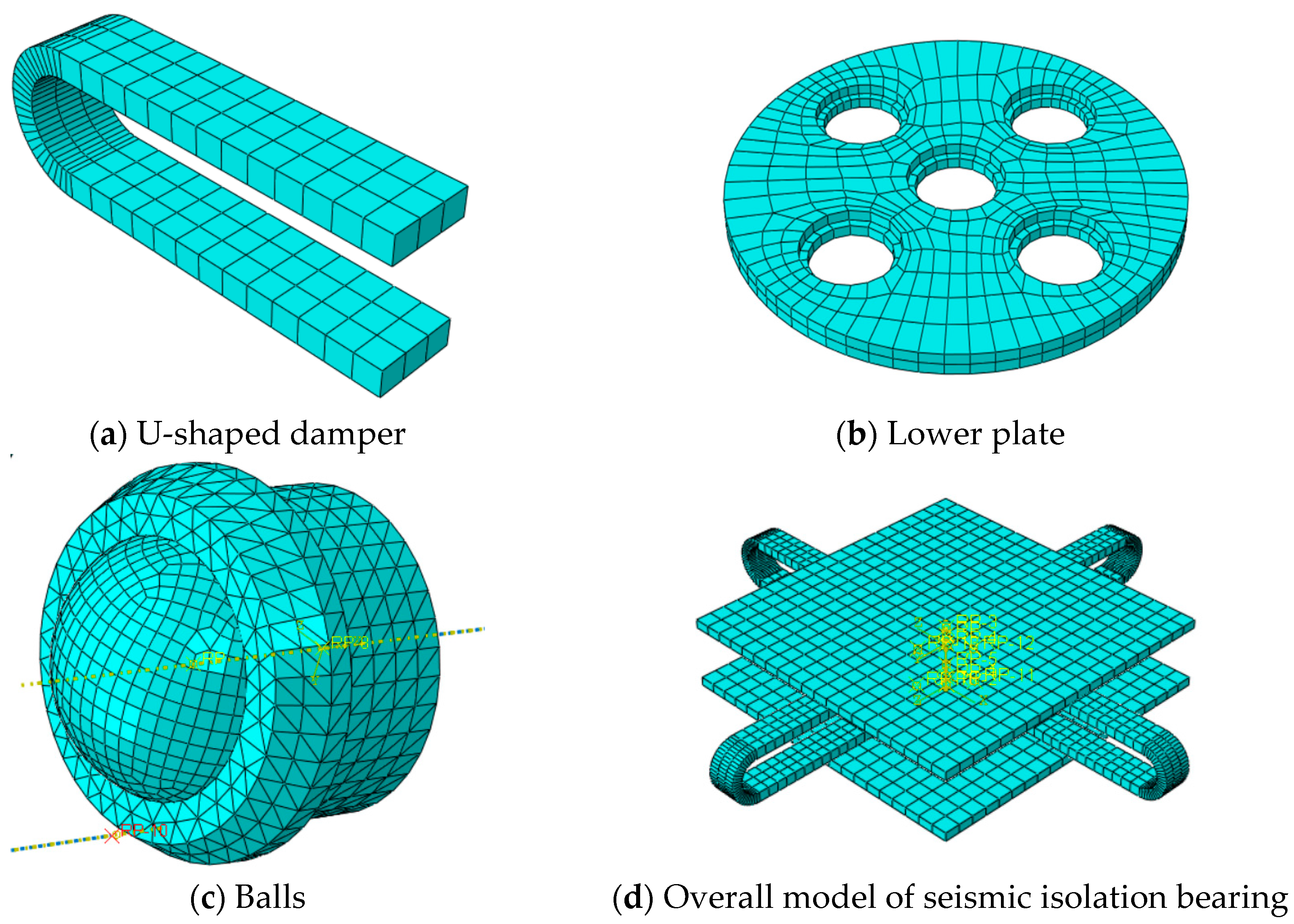
This study focuses on the analysis of a sliding–rolling friction composite seismic isolation bearing, with boundary conditions set according to the initial constraints of the bearing. The lower section of the friction plate is immobile, thus restricting the degrees of freedom in the X, Y, and Z directions to ensure stable initial boundary conditions. In the preliminary analysis, a reference point RP3 is established on the upper friction plate. Subsequently, the upper surface of the plate is linked with RP3, and axial pressure of 200 Kn along with gravity is applied to the upper part of RP3, resulting in surface loading on the top of the upper friction plate. In the subsequent phase of the analysis, the model is subjected to a loading regime involving horizontal displacement in the direction of U1 to investigate its mechanical response. The objective is to comprehend the behavior of the model when subjected to horizontal displacement.
For the load step treatment, this paper employs a cyclic loading regime controlled by displacement loading. Displacement loading control is preferred because it directly controls the bearing’s displacement variable, more accurately simulating the specific working conditions in the actual project. The study aimed to investigate the mechanical behavior of seismic isolation bearings under different horizontal displacements. The amplitude of displacement loading was increased by 15 mm in each cycle. The loading regime was cycled five times.

3.6. Grid Division

To ensure efficient, stable, and fast computation in finite element analysis, the number of meshes must be determined by weighing the following three aspects: 1. selecting a reasonable cell type; 2. ensuring good cell shape; and 3. strictly controlling mesh density based on size [15].
To regulate mesh density, this paper employs a strategy that combines splitting component entities and arranging seeds. This approach ensures that the mesh arrangement meets both computational accuracy requirements and efficiency considerations. Secondly, to ensure a smooth transition between meshes, we have adopted the mesh transition technique. This technique effectively avoids errors that may occur due to sudden changes in meshes and improves the accuracy of the analysis.
Figure 3 shows that detailed meshing was performed for critical areas of the model, such as the stress concentration area near the bend of the U-shaped damper and the contact portion of the lower connecting plate with the ball. This fine meshing helps to accurately analyze the model’s behavior in these critical regions and predict its performance more accurately. For non-core regions, the mesh size was appropriately increased to improve computational efficiency. This strategy ensures computational accuracy and analytical efficiency, providing a solid foundation for comprehensive evaluation of the performance of sliding–rolling friction composite seismic isolation bearings.

4. Hysteresis Curve Analysis of Sliding–Rolling Friction Composite Seismic Isolation Bearings

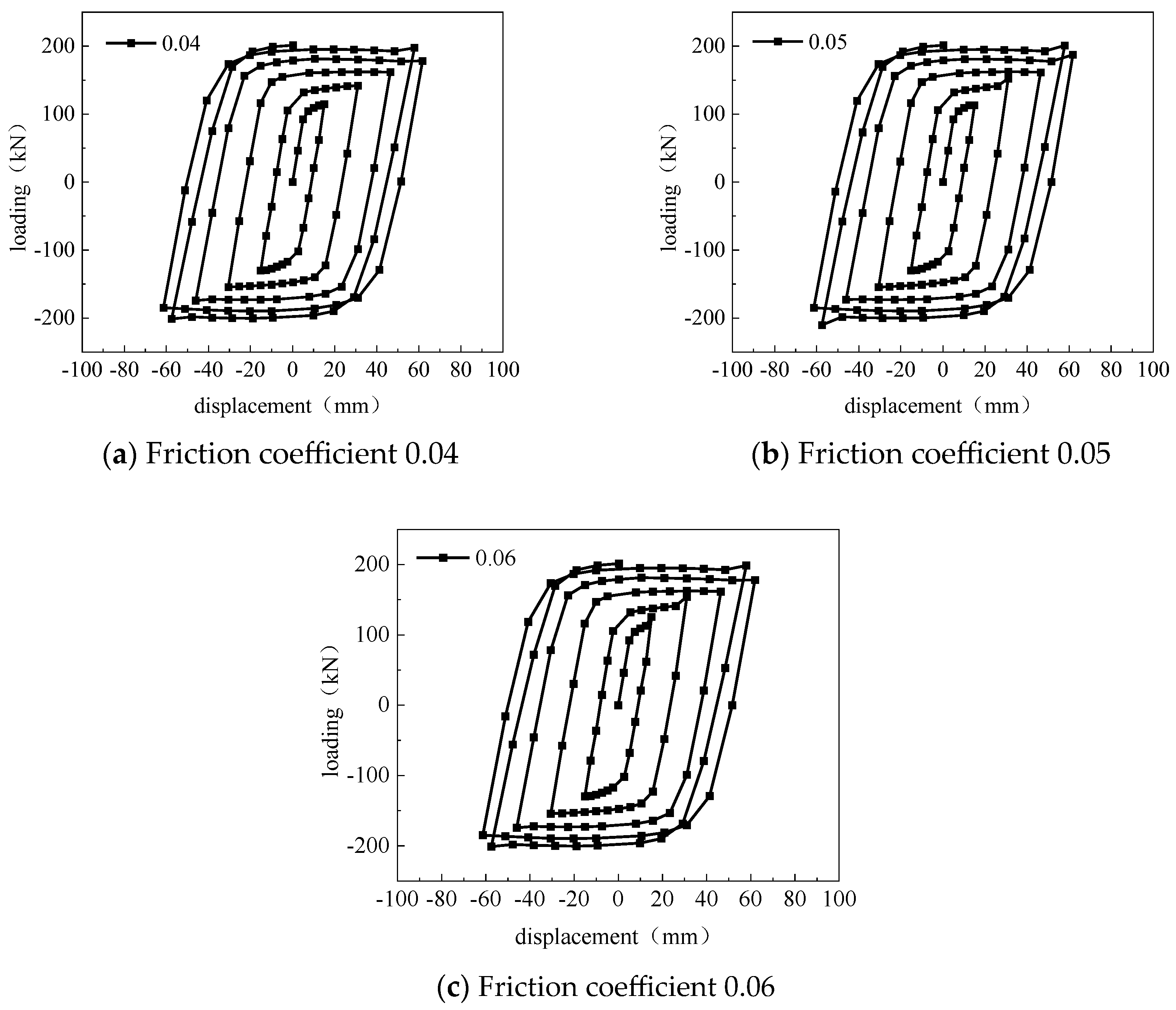
4.1. Effect of Friction Coefficient on Hysteresis Curve

The hysteresis curve characterizes the energy dissipation generated by the elastic–plastic deformation of a structure or component. The size of the hysteresis loop area enclosed by the cyclic motion in one cycle is used as the evaluation criterion. The fuller the shape of the curve and the larger the area, the stronger the energy dissipation capacity and the better the seismic performance of the structure or component. To investigate the effect of friction coefficient on the seismic isolation performance of sliding–rolling friction composite isolation bearings, numerical simulations were conducted. The bearing was set to have zero balls and shims, and four U-shaped dampers with a width of 40 mm (at an angle of 90°) were arranged around it. Hysteresis curves were obtained for the seismic isolation bearing with friction coefficients of 0.04, 0.05, and 0.06, respectively. Figure 4 illustrates the energy dissipation capacity performance of the seismic isolation bearing at varying friction coefficients.
Based on the hysteresis curves in Figure 4, it is evident that the sliding–rolling friction composite seismic isolation bearings exhibit a complete shuttle shape, regardless of the variation in friction coefficient. This aligns with the elastic–plastic energy dissipation model. Furthermore, after reaching the yield point. the hysteresis curves remain almost parallel due to the small differences between the analyzed friction coefficients.
When the friction coefficient is increased from 0.04 to 0.06, the maximum damping force of the seismic isolation bearings changes from 201.34 kN to 201.45 kN. This indicates that the increase in friction coefficient does not significantly affect the maximum damping force.
Based on the hysteresis curve data presented in Table 2, it is evident that an increase in the friction coefficient from 0.04 to 0.05 results in a decrease of 0.16% and 0.24% in the hysteresis loop area and equivalent damping ratio, respectively. Similarly, an increase in the friction coefficient from 0.05 to 0.06 leads to a decrease of 0.12% and 0.24% in the hysteresis loop area and equivalent damping ratio, respectively. This indicates that the change of the friction coefficient has a very limited effect on the energy dissipation capacity of the seismic isolation bearings and further confirms that the change of the friction coefficient does not have a significant effect on the improvement of the performance of the bearings.
After comprehensive consideration, a friction coefficient of 0.04 was selected to ensure that the seismic isolation bearing maintains its energy-consuming performance while effectively realizing the seismic isolation effect.

4.2. Effect of the Number of U-Dampers on the Hysteresis Curve

The U-shaped damper is arranged based on the angle between it and the horizontal displacement loading direction of the sliding–rolling friction composite seismic isolation bearing: ‘0°’ when the two directions are the same, ‘45°’ at an angle of 45°, and ‘90°’ vertically. The arrangement options are that the ‘90°’ arrangement is used when the two directions are the same. Figure 5 displays the number and arrangement of dampers considered in the simulation.
To investigate the influence of the number of U-dampers on the seismic isolation performance of the bearing, numerical simulations were conducted. The experimental conditions maintained a consistent number of shims and balls, a friction coefficient of 0.05, and a U-damper width of 60 mm. The seismic isolation bearing configurations included zero, two, four, and eight U-dampers, and hysteresis curves were generated under different U-damper quantities. Figure 6 illustrates the hysteresis curves corresponding to various numbers of U-dampers.
The hysteresis curve in Figure 6 shows that the support experiences significant slip during the stressing process when there is no U-shaped damper in action, as evidenced by the clear rectangular shape of the curve. The bearing provides almost no resistance during the loading phase, allowing slip to accumulate rapidly and potentially impacting the structural stability. During the unloading stage, residual deformation significantly impacted the overall performance of the structure due to incomplete recovery from slip-induced deformation. The addition of a U-shaped damper improved the energy dissipation capacity and stability of the support, as evidenced by the hysteresis curve changing from a rectangular to a full shuttle shape. The hysteresis curve of the bearing has a shuttle shape, which bends noticeably during both the loading and unloading phases. This indicates that the bearing can effectively absorb and dissipate energy during the stressing process, thereby enhancing the seismic performance and stability of the structure.
From a quantitative perspective, the maximum damping force exhibits a notable increase from 61.11 kN to 172.237 kN when the number of U-dampers is augmented from zero to two. This is attributed to the fact that the enhancement in stiffness resulting from the increase in the number of U-dampers implies the introduction of more energy-consuming units for energy dissipation. Subsequently, increasing the number of U-dampers from two to four leads to a further increase in the maximum damping force, from 164.545 kN to 543.278 kN. Moreover, expanding the number of dampers from four to eight yields a maximum damping force of 855.845 kN. These findings illustrate a notable upward trend in the maximum damping force of the seismic isolation bearing with an increase in the number of U-dampers. The inclusion of U-shaped dampers augments the overall energy dissipation capacity and stability of the structure by absorbing and dissipating energy under external forces, thereby enhancing the maximum damping force. This approach proves effective and pragmatic in achieving these objectives.
The maximum damping force increases from 164.545 kN to 172.237 kN when there are two dampers, indicating a slight influence of the arrangement mode on the damping force. However, with four dampers, the maximum damping force varies significantly depending on the arrangement. When distributed at a 45° angle, the maximum damping force reaches 543.278 kN, while at a 90° angle, it decreases to 336.369 kN. This suggests that a well-planned arrangement can distribute U-shaped dampers more evenly in space, reducing stress concentration and facilitating a uniform dispersion of external force among the dampers. This, in turn, enhances the efficiency of each damper, improving the stability and energy consumption capacity of the entire structure.
Based on the hysteresis curves presented in Table 3, it is evident that the quantity and arrangement of U-dampers have a substantial impact on both the hysteresis loop area and the equivalent damping ratio.
Regarding the change in quantity, as the number of dampers increased from zero to two, the hysteresis loop area and equivalent damping ratio increased by 185.52% and 5.69%, respectively. Similarly, when the number of dampers increased from two to four, the hysteresis loop area and equivalent damping ratio increased by 235.62% and 6.56%, respectively. However, when the number of dampers increased from four to eight, the hysteresis loop area increased by 176.1%, but the equivalent damping ratio decreased by −0.44%. The results demonstrate that the hysteresis loop area, which is surrounded by force and displacement, shows a clear increasing trend with the addition of U-shaped dampers. This verifies that increasing the number of U-shaped dampers can effectively enhance the energy dissipation capacity of seismic isolation bearings. However, increasing the number of U-shaped dampers beyond a certain point does not increase the equivalent damping ratio. This may be due to the uneven distribution of energy dissipation caused by too many dampers, resulting in some dampers failing to fully play their role in energy dissipation.
Regarding the arrangement, when there are two U-type dampers arranged from 0° to 90°, the hysteresis loop area decreases by 9.11%, and the equivalent damping ratio increases by 9.54%. When there are four U-type dampers arranged from 45° to 90°, the hysteresis loop area decreases by 0.9%, and the equivalent damping ratio increases by 4.19%. This demonstrates that when the number of dampers is fixed, the arrangement has a relatively minor impact on the hysteresis loop area, but a more noticeable effect on the equivalent damping ratio.
Therefore, when selecting the number of U-dampers, it is important to consider not only the enhancement of the energy dissipation capacity of the seismic isolation bearing but also the influence of its arrangement on the equivalent damping ratio. This will help achieve the optimal balance between seismic isolation performance and cost. Taken together, the arrangement of four U-dampers at a 45° angle has the most outstanding performance in improving the energy dissipation and damping characteristics of the seismic isolation bearing. Therefore, it is the optimal choice for efficient energy dissipation.

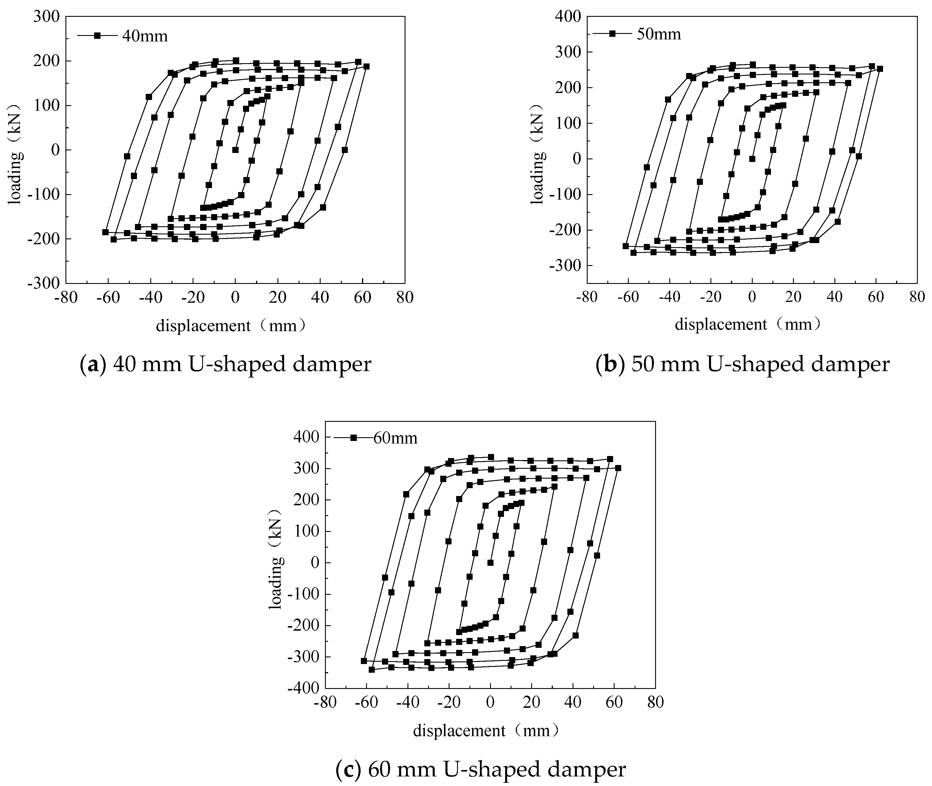
4.3. Effect of U-Damper Width on Hysteresis Curve

Numerical simulations were conducted to investigate the impact of U-shaped damper width on the seismic isolation performance of the bearing. The U-shaped damper widths of 40 mm, 50 mm, and 60 mm were tested while keeping the number of shims and balls constant and maintaining a coefficient of friction of 0. Figure 7 shows the hysteresis curves of the vibration isolation bearings with four U-shaped dampers arranged at 90° and different widths. The figure also demonstrates the energy dissipation performance of the bearings under the action of different U-shaped damper widths.
Based on the hysteresis curve in Figure 7, it is evident that the full shuttle shape is maintained regardless of the width of the U-shaped damper. This aligns with the characteristics of the elastic-plastic energy dissipation model. Increasing the width of the damper from 40 mm to 50 mm results in an increase of the maximum damping force of the seismic isolation bearing from 201.289 kN to 265.743 kN. Similarly, increasing the width from 50 mm to 60 mm results in a further increase of the maximum damping force from 265.743 kN to 336.369 kN. With an increase in damper width, the maximum damping force of the seismic isolation bearing shows a clear upward trend. This is due to the wider U-shaped damper providing a larger contact area, resulting in more material involved in the deformation and energy dissipation process, thus generating a greater damping force. Furthermore, as the damper width increases, its internal stress distribution becomes more uniform, reducing the occurrence of stress concentration, and ultimately enhancing the damper’s load-carrying capacity and energy dissipation performance.
Based on the hysteresis curve data presented in Table 4, it is evident that the energy dissipation performance of the seismic isolation bearing increases significantly with the widening of the U-shaped damper. Increasing the width of the damper from 40 mm to 50 mm significantly increases the hysteresis loop area and equivalent damping ratio by 26.08% and 24.07%, respectively. This suggests that widening the damper can effectively enhance the energy dissipation capacity of the seismic isolation bearing. When the width was increased from 50 mm to 60 mm, the hysteresis loop area and equivalent damping ratio increased by 20.43% and −0.69%, respectively. This suggests that increasing the width has a positive effect on energy dissipation, but the enhancement of damping performance may gradually weaken as the width continues to increase.
Increasing the width of the U-shaped damper is an effective strategy for enhancing the energy dissipation capacity and stability of seismic isolation bearings. After considering all factors, a width of 60 mm is recommended for the U-shaped damper. This width ensures good stability while maintaining a high energy dissipation capacity for the seismic isolation bearing.

4.4. Effect of Number of Balls on Hysteresis Curve

To examine the impact of the number of balls on the seismic isolation performance of the bearing, we utilized the control variable method to investigate how changes in the number of balls affect the bearing’s performance. The mechanical behavior of isolation bearings with different numbers of balls was simulated in ABAQUS. Hysteresis curves were obtained to visualize the energy dissipation performance of the bearings under the action of different balls, as shown in Figure 8.
Based on the hysteresis curves in Figure 8, it is evident that the curves exhibit a complete shuttle shape when subjected to different balls, consistent with the characteristics of the elastic–plastic energy dissipation model. When the number of balls increases from zero to one, the maximum damping force decreases from 304.69 kN to 266.942 kN. This is mainly due to the intervention of the balls, which changes the contact state of the support. As a result, it becomes easier for the support to undergo relative displacement when subjected to external force, thus reducing the friction damping force. When the number of balls increases from one to four, the maximum damping force increases from 266.942 kN to 336.48 kN. This is due to the interaction between the balls, which restricts the displacement of the bearing and improves the damping force. When the number of balls increases from four to five, the maximum damping force only slightly increases from 336.48 kN to 337.794 kN. This suggests that as the number of balls increases, the enhancement of the maximum damping force gradually decreases and may even reach saturation. This is because having too many balls can complicate the transfer of energy between them, leading to the dissipation of energy in the form of heat. This can also hinder the increase of the damping force.
Based on the hysteresis curve data presented in Table 5, it is evident that the hysteresis loop area enclosed by force and displacement and the equivalent damping ratio exhibit an increasing-then-decreasing trend with the increase in the number of balls. When the number of balls increases from zero to one, the hysteresis loop area and equivalent damping ratio increase by 8.22% and 15.34%, respectively. This indicates that the addition of balls has a positive effect on the energy dissipation capacity of the seismic isolation bearing, which in turn effectively enhances the seismic performance of the structure. When the number of balls increased from one to four, the hysteresis loop area and equivalent damping ratio increased by 30.75% and 4.44%, respectively. This suggests that the growth rate of energy dissipation efficiency was slowing down while maintaining the energy dissipation capacity of the bearing. The interaction of the balls resulted in an increase in the loss of energy in the process of energy transfer and dissipation, which in turn lowered the energy dissipation efficiency of the bearing. When the number of balls increased from four to five, the hysteresis loop area increased by 0.46%, while the equivalent damping ratio remained almost unchanged. This suggests that after a certain number of balls, additional balls have a limited effect on the energy dissipation capacity and efficiency of the support.
When designing seismic isolation bearings, it is important to balance the number of balls with energy consumption and efficiency to achieve optimal performance. Therefore, selecting four balls is a more reasonable choice.

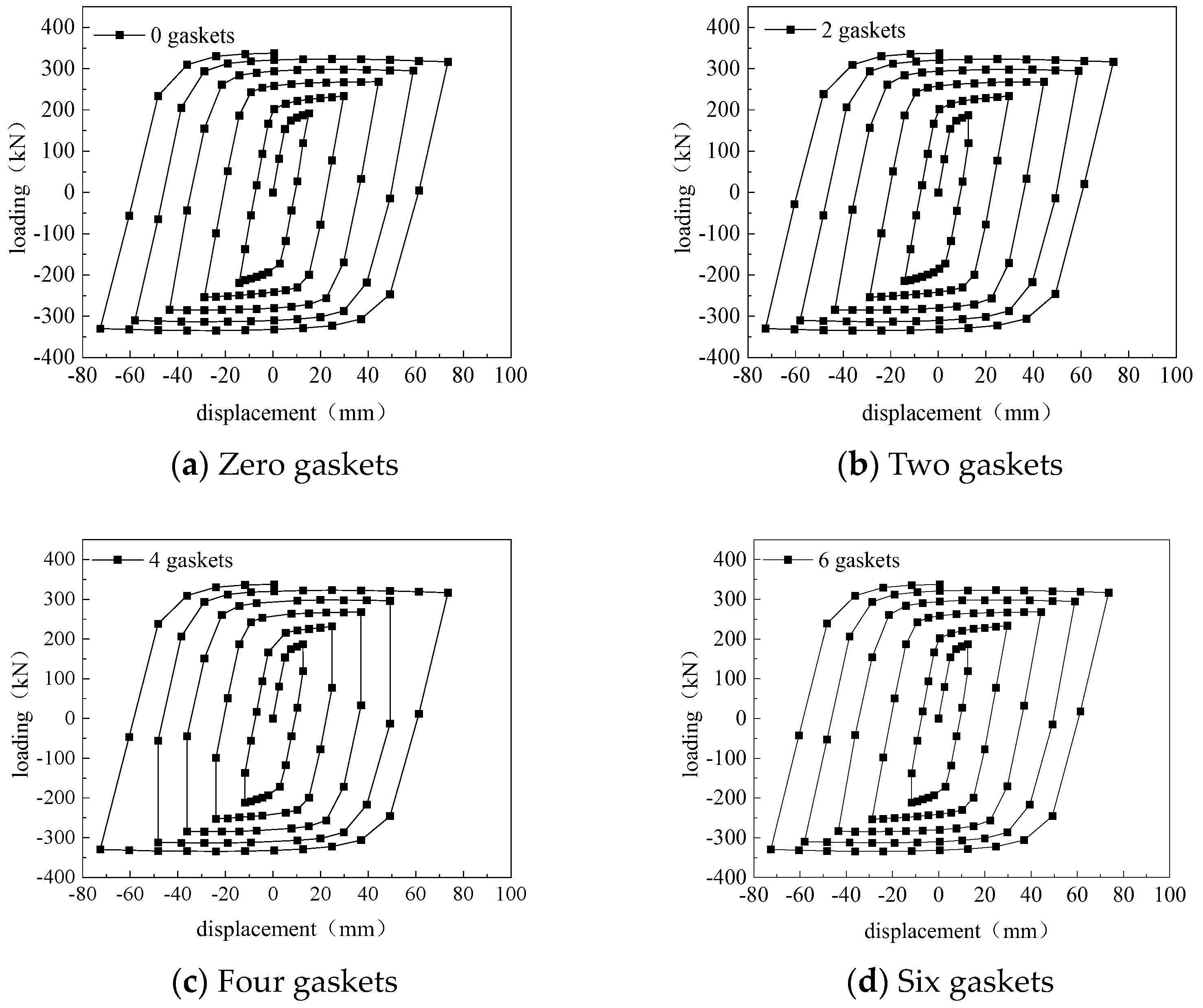
4.5. Effect of Number of Shims on Hysteresis Curve

According to the shape of the hysteresis curve in Figure 9 and the hysteresis curve data in Table 6, it is evident that the curve maintains a full pike shape regardless of the number of shims used. This is consistent with the characteristics of the elastic-plastic energy dissipation model. When the number of shims increases from zero to two, the maximum damping force increases from 307.794 kN to 338.599 kN. This is because the increase in the number of shims enhances the spring pre-stress, causing the ball group to share more loads and form a more effective synergistic effect with the sliding surface. When the number of shims increases from two to four, the maximum damping force decreases from 338.599 kN to 337.618 kN. Further increasing the number of shims to six results in a decrease in the maximum damping force to 337.44 kN. This decrease is due to excessive shims, which cause excessive spring prestressing. As a result, the ball group shares too much load, and the energy dissipation of the sliding surface decreases.

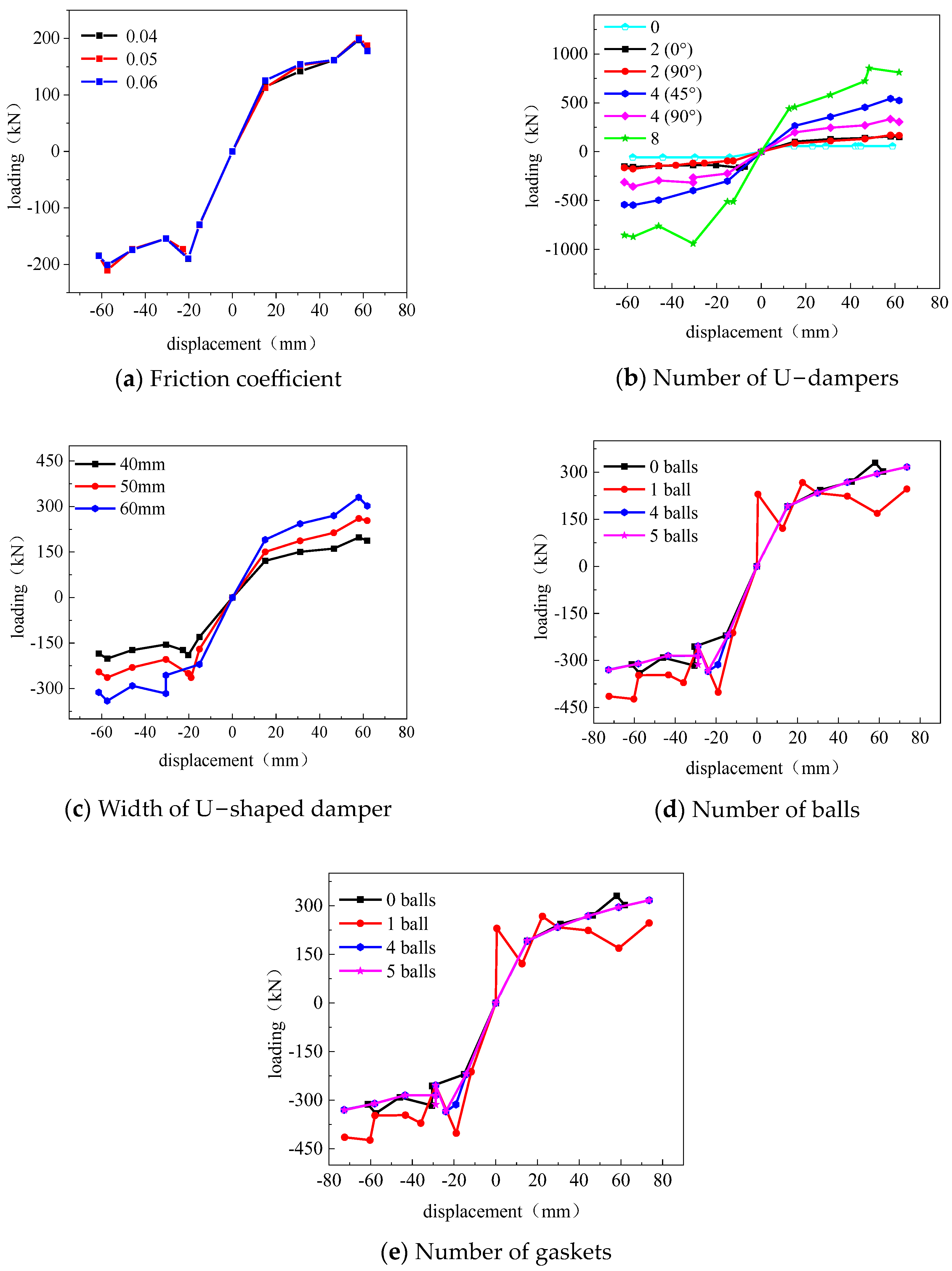
5. Skeleton Curve Analysis of Sliding–Rolling Friction Composite Seismic Isolation Bearings

5.1. Analysis Curves for Different Parts of the Skeleton

After analyzing the hysteresis curve data in Section 3, we plotted the variation of the skeleton curve of the isolation bearing under different parameters in Figure 10.
Based on the skeleton curve presented in Figure 10, it is evident that the width and number of U-dampers, as well as the number of balls, have a more significant impact on the bearing compared to changes in the coefficient of friction and the number of shims. Therefore, when designing seismic isolation bearings, it is crucial to prioritize the width, number of U-dampers, and number of balls.
Therefore, the next step is to analyze the skeleton curve formed by the width and number of U-shaped dampers and the number of ball rollers. Then, the optimal design parameters of the seismic isolation bearing can be determined by analyzing key data indexes such as the ductility coefficient, yielding load, yielding displacement, and ultimate load under different parameters.

5.2. Analysis of the Characteristic Parameters of the Skeleton Curve

The key performance data were statistically derived from the skeleton curves provided above.
Table 7 shows the performance indexes of the bearing parameters. The ultimate load, yield load, and ductility of the seismic isolation bearings are significantly affected by the number and arrangement method of U-type dampers. In terms of quantity, the yield load, ultimate load, and ductility coefficient increased by approximately 81.89%, 119.62%, and 32.52%, respectively, when the number of dampers increased from zero to two. Similarly, when the number of dampers increased from two to four, the yield load, ultimate load, and ductility coefficient increased by approximately 156.01%, 244.08%, and 11.74%. The yield load and ductility coefficient increased by 156.01% and 244.08%, respectively, when the number was increased from four to eight. Similarly, increasing the number from four to seven significantly affected the yield load and ductility coefficients. Further increasing the number to eight increased by about 66.4% in yield load, 57.5% in ultimate load, and 9.2% in ductility coefficient. Increasing the number of dampers can effectively improve the bearing capacity and ductility of seismic isolation bearings. Regarding the arrangement, if there are two dampers, changing the arrangement can increase the yield load, ultimate load, and ductility coefficient by 20.46%, 7.52%, and 34.8%, respectively. If there are four dampers, changing the arrangement will decrease the yield load and ultimate load by 25.23% and 38.4%, respectively, but increase the ductility coefficient by 3.93%.
To ensure stability and safety, the seismic isolation bearing must withstand and disperse horizontal seismic forces during earthquakes. It is necessary to balance the bearing capacity and deformation capacity. Based on the analysis, four U-shaped dampers arranged at 45° are the optimal parameters that meet the performance requirements and ensure the structure’s safety and stability.
Based on the performance indexes of the bearing parameters presented in Table 8, it is evident that the yield load and ultimate load exhibit a significant growth trend with an increase in the width of the U-type damper. Specifically, when the damper width increases from 40 mm to 50 mm, the yield load and ultimate load increase by 24.4% and 31.5%, respectively. Similarly, when the damper width increases from 50 mm to 60 mm, the yield load and ultimate load increase by 31.3% and 28.4%, respectively.
Increasing the damper width improves the ductility performance of seismic isolation bearings, as shown by the overall increasing trend of the ductility coefficient. It is important to note that this evaluation is objective and based solely on the data presented.
Based on the bearing and deformation capacity, the optimal choice is the U-type damper with a width of 60 mm. This damper not only enhances the seismic isolation bearing’s load-bearing capacity but also maintains excellent ductility performance.
Table 9 shows the performance indexes of the bearing parameters. The number of balls has a significant impact on the yield load and ultimate load. As the number of balls increases, the ultimate load and yield load initially decrease and then increase. When the number of balls increased from zero to one, the yield and ultimate load decreased by 39.0% and 26.3%, respectively. This was due to the addition of balls, which altered the original contact state and resulted in a temporary decrease in the load-carrying capacity. When the number of balls was increased from one to four, the yield load and ultimate load increased by 57.5% and 28.5%, respectively. This indicates that the structural load-carrying capacity was effectively enhanced with the further increase in the number of balls. When increasing the number of balls from four to five, the yield load and ultimate load increased only slightly. This suggests that the load-carrying capacity is gradually weakened by increasing the number of balls to a certain extent.
The ductility coefficient shows an increasing and then decreasing effect with the increase in the number of balls. Specifically, from zero to one ball, the ductility coefficient increased by 14.5%, indicating a positive effect of adding a ball. However, when the number of balls increased from one to four, the ductility coefficient decreased by 5.36%, suggesting that a further increase in the number of balls may not always be favorable to the ductility coefficient. Notably, there is almost no difference in the ductility coefficient when the number of balls is four and five.
Based on the comprehensive performance index, the optimal parameter for the number of balls is four. This maintains a high load-carrying capacity while also allowing for good deformation ability.
To ensure a comprehensive analysis, this paper suggests designing the optimal parameters of the sliding–rolling friction composite isolation bearing as follows: a friction coefficient of 0.04, four U-shaped dampers arranged at 45° with a width of 60 mm, four ball rollers, and two shims.

6. Conclusions

According to the concept of performance-based seismic engineering, the seismic loss analysis of eccentrically braced steel frame structures is of great significance for the selection of structural layout. In this paper, different forms of eccentrically braced steel frame structures are designed, which are K-shaped, V-shaped, and D-shaped, respectively, and the vulnerability of the structure and earthquake loss are studied. The main conclusions are as follows.
This study established a model for a sliding–rolling friction composite seismic isolation bearing using ABAQUS software. The model was optimized and analyzed for parameters such as friction coefficient, width of U-dampers, number of U-dampers, number of balls, and number of shims using the method of control variables. After comparing performance indexes, such as hysteresis loop shape, area, and equivalent damping ratio, it is concluded that the width and number of U-dampers, as well as the number of balls, are the key factors that affect the performance of seismic isolation bearings.
The study analyzes the effects of the number of U-shaped dampers, width, and number of balls on the performance of seismic isolation bearings. The characteristic parameters in the skeleton curves are extracted, and key performance indexes such as yield load, ultimate load, and ductility coefficient are compared. This analysis aims to determine the optimal design parameters of the seismic isolation bearings. The recommended parameters for this system are a friction coefficient of 0.04, four U-shaped dampers with a width of 60 mm arranged at a 45° angle, four balls, and two shims.

Author Contributions

Conceptualization, Y.L.; Methodology, J.L.; Software, B.L.; Validation, J.C.; Formal analysis, W.Z.; Investigation, Q.M.; Resources, Q.M.; Writing—original draft, Y.L.; Writing—review & editing, J.L. and B.L. All authors have read and agreed to the published version of the manuscript.

Funding

This research received no external funding.

Data Availability Statement

Data is contained within the article.

Conflicts of Interest

The authors declare that they have no known competing financial interests or personal relationships that could have appeared to influence the work reported in this paper.

References

  1. Lin, X. Seismic Performance Analysis of Frame Structures Using Seismic Isolation Technology. Master’s Thesis, Southeast University, Nanjing, China, 2019. [Google Scholar]
  2. Liu, W.; Zhou, F.; Zhong, X.; Bai, Y. Study on various related properties and long-term performance of lead-core laminated rubber seismic isolation pads. J. South China Constr. Inst. 1999, 12–20. [Google Scholar]
  3. Yang, L.; Liu, Y.; Chang, Y.; Cheng, C.; Sun, F. Global patent analysis of seismic isolation bearing technology. Eng. Seism. Reinf. Retrofit. 2018, 40, 7–12. [Google Scholar]
  4. Yang, L.; Sun, F.; Chang, Y.; Cheng, C. Study on the patent status of building seismic isolation bearing in China. Eng. Seism. Reinf. Retrofit. 2018, 40, 1–6. [Google Scholar]
  5. Li, J. Comparison of Seismic Response Analysis of Frame Structures with Different Isolation Schemes. Master’s Thesis, Shandong University of Architecture, Jinan, China, 2020. [Google Scholar]
  6. Jin, J.; Huang, X.; Zhong, X.; Shen, Z. Study on the value of stiffness before yielding of lead core rubber bearing (LRB) in seismic isolation design. J. Guangzhou Univ. (Nat. Sci. Ed.) 2006, 63–67. [Google Scholar]
  7. Wang, B.; Tan, P.; Xu, K.; Zhou, F.; Ning, L. Experimental study on mechanical properties of new fiber reinforced engineering plastic plate sandwich rubber isolation bearing. J. Civ. Eng. 2012, 45, 187–191. [Google Scholar]
  8. Zayas, V.A.; Low, S.S.; Mahin, S.A. A Simple Pendulum Technique for Achieving Seismic Isolation. Earthq. Spectra 1990, 6, 317–333. [Google Scholar] [CrossRef]
  9. Quaglini, V.; Gandelli, E.; Dubini, P. Experimental investigation of the re-centring capability of curved surface sliders. Struct. Control. Health Monit. 2017, 24, e1870. [Google Scholar] [CrossRef]
  10. Fenz, D.M.; Constantinou, M.C. Behaviour of the double concave Friction Pendulum bearing. Earthq. Eng. Struct. Dyn. 2006, 35, 1403–1424. [Google Scholar] [CrossRef]
  11. Wang, Q.T. Analysis of Vibration Damping Performance of Lead-Core Steel Pipe Seismic Isolation Bearing with Stiffening Ring. Master’s Thesis, Jilin University of Architecture, Changchun, China, 2022. [Google Scholar]
  12. Harvey, P.S.; Wiebe, R.; Gavin, H.P. On the chaotic response of a nonlinear rolling isolation system. Phys. D Nonlinear Phenom. 2013, 256–257, 36–42. [Google Scholar] [CrossRef]
  13. Zhang, J.; Jia, J. Research on the seismic isolation effect of the ring spring–friction pendulum bearing in the dakai underground subway station. Appl. Sci. 2023, 13, 7093. [Google Scholar] [CrossRef]
  14. Sheng, T.; Liu, G.B.; Bian, X.C.; Shi, W.X.; Chen, Y. Development of a three-directional vibration isolator for buildings subject to metro and earthquake-induced vibrations. Eng. Struct. 2022, 252, 113576. [Google Scholar] [CrossRef]
  15. Han, J.; Guo, Z.; Li, M.; Li, L.; Hou, B.; Du, X. Nonlinear seismic response of free-field soil under longitudinal non-uniform seismic excitations. Rock Soil Mech. 2019, 40, 2581–2592. [Google Scholar]
Figure 1. Steel bifold intrinsic model.
Buildings 14 02053 g001
Figure 2. Sliding–rolling friction composite seismic isolation bearing components and overall modeling.
Buildings 14 02053 g002
Figure 3. Mesh delineation of seismic isolation bearing.
Buildings 14 02053 g003
Figure 4. Hysteresis curves under different friction coefficients.
Buildings 14 02053 g004
Figure 5. Arrangement of U-dampers.
Buildings 14 02053 g005
Figure 6. Hysteresis curves under the action of different numbers of U-dampers.
Buildings 14 02053 g006
Figure 7. Hysteresis curves under the action of different U-damper widths.
Buildings 14 02053 g007
Figure 8. Hysteresis curves for different numbers of balls.
Buildings 14 02053 g008
Figure 9. Displays hysteresis curves for various numbers of shims.
Buildings 14 02053 g009
Figure 10. Skeleton curves under different parameters.
Buildings 14 02053 g010
Table 1. Table of material properties.
Makings Modulus of Elasticity (MPa)Poisson’s RatioYield Stress (N/mm2)Mass Density (kg/m3)
45#steel2.11 × 10110.2694307890
65 Mn2.09 × 10110.2883557820
GCr152.06 × 10110.318007810
PTFE2.8 × 10110.3502320
Q3452.11 × 10110.33457890
Table 2. Statistics of hysteresis curves under different friction coefficients.
Coefficient of FrictionHysteresis Loop Area (J)Maximum Value of Displacement in the Cycle (mm)Maximum Value of the Load during the Cycle (kN)Equivalent Damping Ratio
0.0432,11461.86201.340.411
0.0532,060.961.85201.290.41
0.0632,02061.86201.450.409
Table 3. Presents the statistics of the hysteresis curve data when subjected to varying numbers of U-dampers.
Number of DampersHysteresis Loop Area
(J)
Maximum Value of Displacement in the Cycle
(mm)
Maximum Value of the Load during the Cycle
(KN)
Equivalent Damping Ratio
010,019.8558.85261.1100.404
2 (0°)25,887.5061.871164.5450.405
2 (90°)28,606.3661.872172.2370.427
4 (45°)96,009.7461.840543.2780.455
4 (90°)54,508.7361.840336.3690.417
8150,495.9861.808855.8450.453
Table 4. Presents the statistics of the hysteresis curve data when subjected to various U-damper widths.
Damper Width (mm)Hysteresis Loop Area
(J)
Maximum Value of Displacement in the Cycle
(mm)
Maximum Value of the Load during the Cycle
(KN)
Equivalent Damping Ratio
4032,060.961.853201.2890.41
5043,370.761.853265.7430.42
6054,508.761.84336.3690.417
Table 5. Presents the statistics of hysteresis curves obtained with varying numbers of balls.
Number of BallsHysteresis Loop Area (J)Maximum Value of Displacement in the Cycle
(mm)
Maximum Value of the Load during the Cycle
(KN)
Equivalent Damping Ratio
051,284.761.84304.690.39
155,499.673.57266.9420.45
472,567.173.62336.480.47
572,900.173.62337.7940.47
Table 6. Statistics of hysteresis curves under different number of shims.
Number of GasketsHysteresis Loop Area (J)Maximum Value of Displacement in the Cycle (mm)Maximum Value of the Load during the Cycle (kN)Equivalent Damping Ratio
072,900.173.6209307.7940.467
276,806.773.5153338.5990.493
476,648.573.5101337.6180.492
676,632.273.5146337.440.492
Table 7. Shows the performance indexes of the support’s skeleton curve parameters under different numbers of U-dampers.
Number of U-DampersYield Load (kN)Ultimate Load (kN)Yield Displacement (mm)Limit Displacement
(mm)
Ductility Factor
056.8161.1114.1858.872.06
2 (0°)103.33134.2115.0446.482.73
2 (90°)85.78144.315.0451.543.68
4 (45°)264.54461.816.3347.53.05
4 (90°)197.8284.4815.0347.033.17
4 (45°)440.47727.4715.0246.493.33
Table 8. Shows the performance indexes of the support’s skeleton curve parameters under different widths of U-dampers.
Width of U-DampersYield Load (kN)Ultimate Load (kN)Yield Displacement (mm)Limit Displacement
(mm)
Ductility Factor
40120.93168.3815.0347.043.08
50150.48221.4915.0346.923.07
60197.80284.4815.0347.033.17
Table 9. Shows the performance indexes of the support’s skeleton curve parameters under different number of balls.
Number of BallsYield Load (kN)Ultimate Load (kN)Yield Displacement (mm)Limit Displacement
(mm)
Ductility Factor
0197.80284.4815.0347.033.17
1120.88209.4912.6343.564.16
4190.83269.2515.0744.353.00
5192.04269.3115.0744.413.00
Disclaimer/Publisher’s Note: The statements, opinions and data contained in all publications are solely those of the individual author(s) and contributor(s) and not of MDPI and/or the editor(s). MDPI and/or the editor(s) disclaim responsibility for any injury to people or property resulting from any ideas, methods, instructions or products referred to in the content.

