Article

Numerical Parameter Analysis of High-Strength Steel Frame with Y-Eccentric Brace Using Variable Replaceable Link

School of Civil Engineering and Construction, Xi’an University of Technology, Xi’an 710048, China
*
Author to whom correspondence should be addressed.
Buildings 2024, 14(7), 2149; https://doi.org/10.3390/buildings14072149
Submission received: 19 June 2024 / Revised: 8 July 2024 / Accepted: 9 July 2024 / Published: 12 July 2024

Abstract

:
The present study proposes a variable replaceable link for high-strength steel frames with Y-eccentric braces designed to effectively dissipate earthquake energy by confining plastic deformation to its central zone. This unique feature allows for easy post-earthquake recovery or replacement. To investigate the seismic performance of such structures, a comprehensive finite element numerical parametric analysis is conducted using ABAQUS software. Various parameters, including the length of the central zone, replaceable link length, span, and steel grade are considered to optimize the structural design. This study examines the failure modes, hysteretic behavior, bearing capacity, plastic rotation of the replaceable link, and ductility of structures under cyclic loading. The results indicate that reducing the span and utilizing high-strength steel significantly enhance the ductility and ultimate bearing capacity of the structure. This approach also reduces the cross-sectional dimensions, saves steel material, and limits the development area of plasticity, thereby facilitating post-earthquake repair of links after rare earthquakes. An optimal length of the link improves the structural stiffness and energy dissipation capacity. However, if it is too short or too long, it complicates post-earthquake repairs and impairs energy dissipation performance. The conclusions drawn from this research aim to provide valuable insights and theoretical foundations for future structural designs.

1. Introduction

Steel structures have consistently demonstrated exceptional seismic performance in previous earthquakes, establishing them as the preferred choice in the construction industry. This preference has been further reinforced due to advancements in design, manufacturing, and installation technologies. Li et al. [1] conducted a remote collaborative hybrid test (RCHT) using the OpenFresco platform, demonstrating that the Y-shaped eccentric brace high-strength steel frame (YEB-HSSF) structure satisfies the seismic performance requirements specified in GB 50011-2010 [2]. The structure effectively maintained controlled inter-story drift angles and shear distribution ratios under both frequent and rare earthquake intensities. Keivan et al. [3] demonstrated that a Y-type self-centering eccentrically braced frame (SCEBF-Y) incorporating replaceable energy dissipation devices can achieve strength and stiffness comparable to conventional eccentrically braced frames (EBFs). Furthermore, the SCEBF-Y retains a recentering capability and exhibits minimal residual drift following seismic events. The performance of the SCEBF-Y can be tailored by adjusting the properties of the post-tensioning strands and cable lengths. The seismic performance of eccentrically braced hybrid frames with extremely short shear links and flush endplate bolted connections was investigated by Ma et al. [4]. Their study demonstrated that these configurations exhibit satisfactory performance metrics, including an overstrength coefficient of approximately 1.8 and an ultimate plastic rotation exceeding 0.12 rad. This research highlights the significant influence of factors such as the link length ratio on the structural behavior of these systems. The methodology proposed by Li et al. [5] presents a robust approach for evaluating the elastic stiffness and bearing capacity of eccentrically braced steel frames with K-type, D-type, and V-type configurations. Their study successfully validated the accuracy of the predicted elastic stiffness, yield strength, and ultimate bearing capacities, demonstrating consistent results within a 10% margin when compared with both finite element analysis and experimental data. Zheng et al. [6,7,8,9] proposed hybrid Bayesian copula and AI Bayesian methodologies to evaluate wind-induced risk, seismic resilience, and time-variant seismic fragility in high-rise structures by incorporating aleatory and epistemic uncertainties associated with the dynamic excitations, input loads, cost ratio, recovery time, and corrosion initiation. The study conducted by Lettieri et al. [10] investigated a solution for damage-free, self-centering eccentrically braced frames (EBFs) using seismic links known as self-centering devices (SC-links). This system incorporates post-tensioned high-strength steel bars, disk springs, and friction dampers. Through analytical and finite element models, the authors demonstrated that this innovative approach offers optimized strength, stiffness, and ductility while minimizing the residual and peak story drift angles as well as link rotations. Almasabha et al. [11] conducted an assessment on the accuracy of the AISC 341-16 equation in predicting the shear strength of short links and proposed a simple truss model (STM) which incorporates strain hardening, surpassing the predictive capability of the AISC equation. The mean overstrength values for built-up and rolled W-shape specimens were found to be 1.21 and 1.15, respectively, indicating the superior predictive accuracy of the STM and suggesting its adoption. Yin et al. [12] introduced an eccentrically buckling-restrained braced frame with web-bolted replaceable links which improves seismic performance and the ease of post-earthquake repairs, demonstrating the links’ efficacy as a “structural fuse”. Montuori et al. [13] proposed a theory of plastic mechanism control for eccentrically braced frames, with a specific focus on EB frames employing an inverted Y scheme in order to ensure the establishment of a robust global collapse mechanism, which is crucial for earthquake-resistant design. The methodology involves designing vertical link elements based on seismic forces, incorporating second-order effects through mechanism equilibrium curves, and assessing accuracy by means of push-over analyses. The performance of bolted and welded repairable fuse devices in earthquake-resistant composite steel frames was investigated by Valente et al. [14]. Through a combination of experimental tests and numerical analyses, they were able to identify significant differences in hysteretic behavior and failure modes between the two solutions, ultimately demonstrating their effectiveness. The seismic response of composite frames was investigated by Vasdravellis et al. [15], with a specific focus on the influence of partial composite action between the concrete slab and steel beam, as well as the impact of partial-strength connections. Eccentrically braced steel frame systems offer notable advantages, including exceptional lateral stiffness and effective dissipation of energy. These systems primarily rely on links to withstand seismic forces and absorb earthquake-induced energy release. This design ensures that the links yield first under seismic action for easy replacement after an earthquake. Consequently, the utilization of replaceable links has been widely adopted in seismic structural systems as an efficient approach to achieving commendable seismic performance and post-earthquake recoverability [16,17]. However, experimental findings on conventional Y-shaped eccentrically braced steel frames have consistently demonstrated that the uneven distribution of bending moments at both ends of the links often leads to failures in bending shear under seismic loading. Consequently, these structures exhibit suboptimal performance in terms of energy dissipation [13,18].
To address the deficiencies of conventional Y-shaped eccentrically braced steel frames, this study proposes a structural form which enables rapid post-earthquake recovery: a high-strength, steel composite Y-shaped eccentrically braced structure with replaceable links. The links and braces are constructed using traditional steel, while other components utilize high-strength steel. The variable cross-section design of the links allows for energy dissipation through a smaller energy-dissipating area during significant seismic events, ensuring shear failure and maintaining primary frame stability. Incorporating high-strength steel in non-energy-dissipating components reduces material waste, construction costs, and the overall structure weight, thereby reducing seismic forces. Due to its high lateral stiffness, an eccentrically braced structure exhibits minimal residual deformations after an earthquake, facilitating rapid structural recovery by simply replacing damaged links. In contrast to the challenging, time-consuming, and costly repairs required for traditional eccentrically braced steel frames following earthquakes, this novel structure offers quick restoration through link replacement while also preventing bending shear failure and enhancing energy dissipation effectiveness. To achieve efficient post-earthquake repair of links, a performance-based seismic design method [19] is employed in this study which demonstrates superior seismic performance levels compared with conventional approaches. Parametric analysis of high-strength steel frames with Y-shaped eccentric braces and replaceable links was conducted using finite element software. The findings from this research have significant implications for practical engineering applications of eccentrically braced structural systems and promote the utilization of high-strength steel in seismic design regions.

2. Finite Element Model Validation

To validate the suitability of replaceable links, a finite element model was employed in this study to replicate the experiment described in [20]. A half-scale model with a span of 3000 mm and a story height of 2800 mm was utilized. The dimensions and detailed measurements of the specimen are illustrated in Figure 1. H-shaped steel was used for the frame beams, frame columns, and links. ST37 steel (equivalent to Chinese Q235B carbon structural steel) was employed for the frame beams and links, while ST52 steel (equivalent to Chinese Q355 steel) was used for other components. The connection between the frame beam and link involved eight M20 high-strength bolts with a diameter of 20 mm. Stiffeners, positioned at intervals 170 mm apart from each other and having a thickness of 12 mm, were located at the flanges where the frame columns connected to the frame beams.
The material properties were modeled using the approach proposed by Kaufmann et al. [21], which is based on cyclic coupon tests. ST52 steel, with a nominal yield stress of 370 MPa, was utilized for the columns and associated components, such as the doubler plates, stiffeners, end plates, and continuity plates. The panel zone strength was controlled according to ANSI/AISC 341–16 [22]. The plasticity of the steel was represented by employing the Von Mises yield surface and an associated flow rule. A combined nonlinear isotropic and kinematic strain hardening approach was employed for the hardening model. Furthermore, a steel material elastic modulus of 200,000 MPa and Poisson’s ratio of 0.3 were adopted. Detailed information regarding the material properties and section dimensions of all components can be found in Table 1 and Table 2.

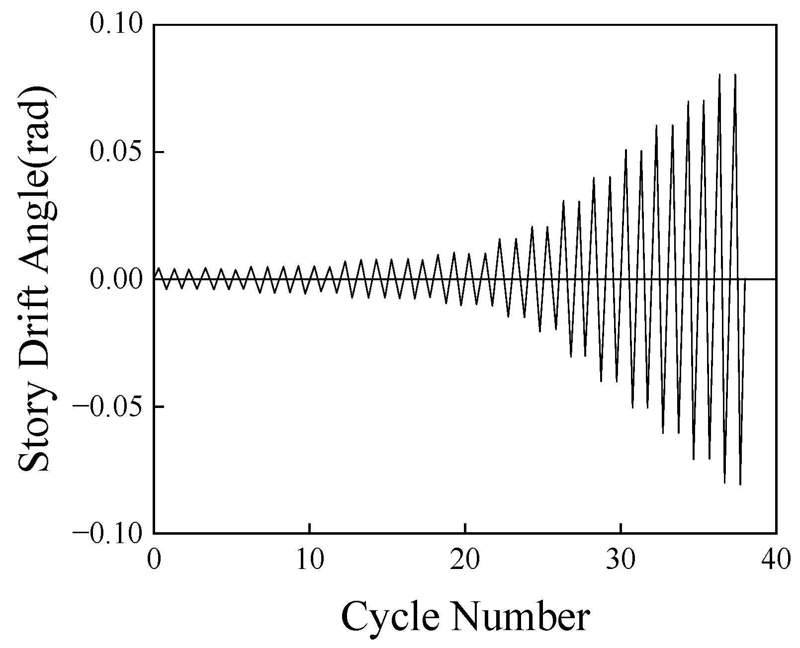
2.1. Loading Protocol

The loading protocol for this experiment initially consisted of six cycles with an amplitude of 0.00375 rad, followed by six cycles each with amplitudes of 0.005 rad and 0.0075 rad. Subsequently, four cycles were conducted with an amplitude of 0.01 rad. Finally, additional cycles were performed sequentially in a stepwise manner as depicted in Figure 2, with increasing amplitudes of 0.015 rad, 0.02 rad, 0.03 rad, and 0.04 rad.

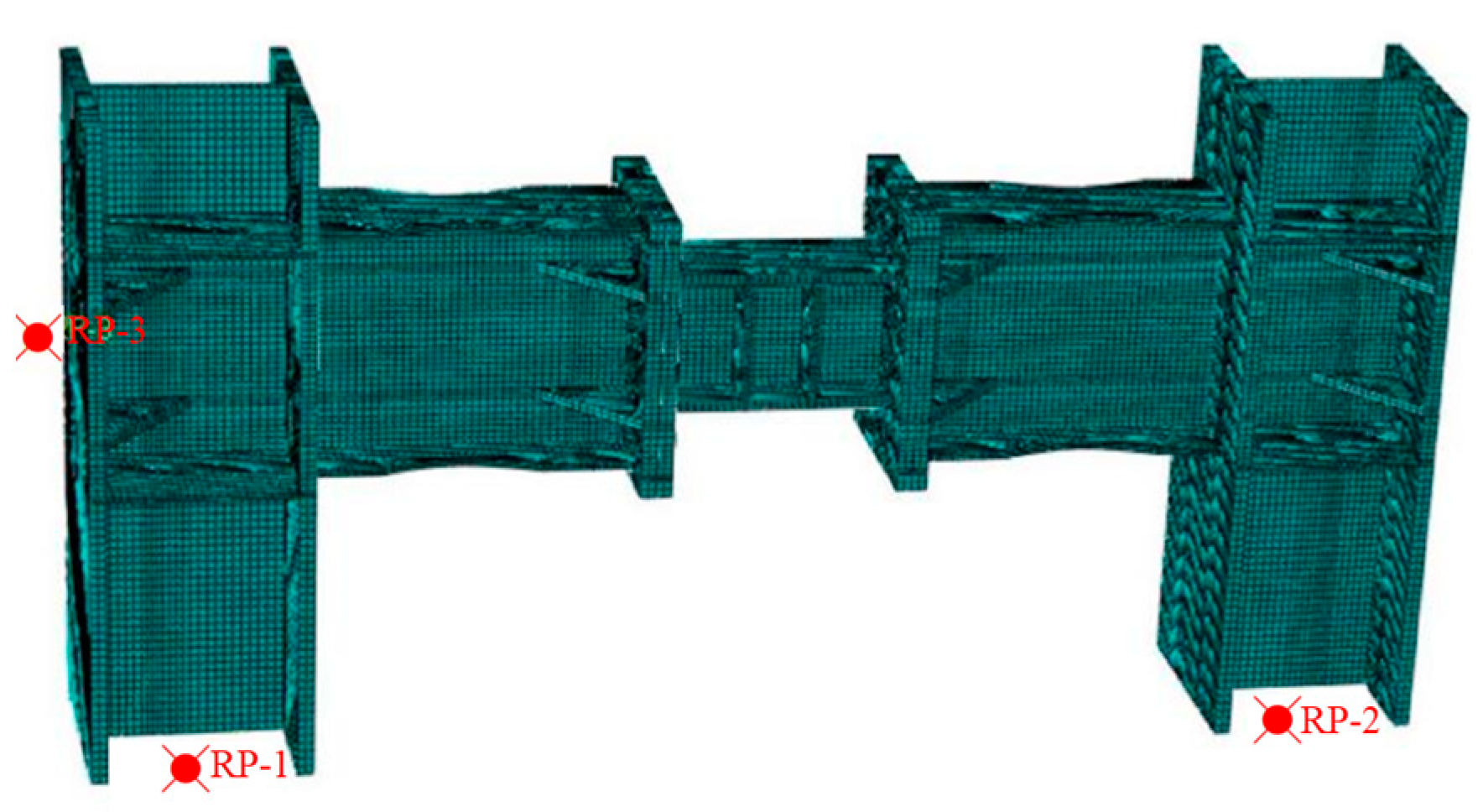
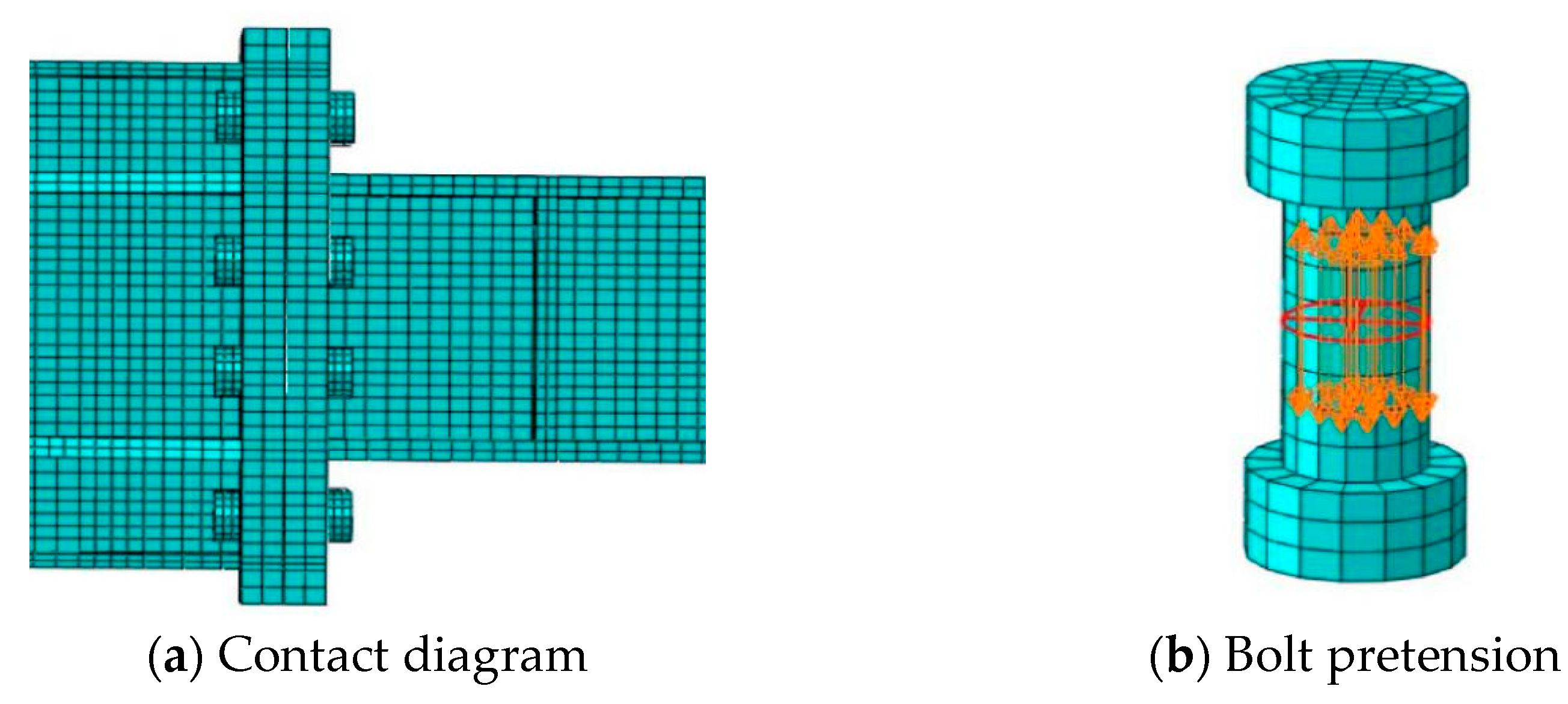
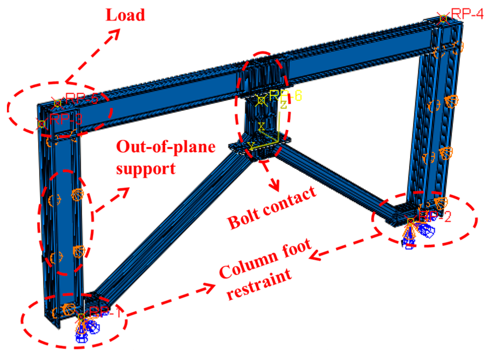
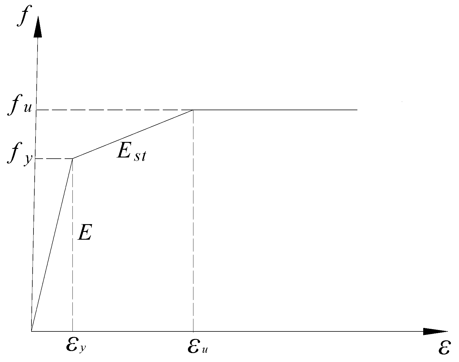
2.2. Finite Element Simulation

The finite element models were created using solid elements to ensure accurate representation. To enhance the efficiency of the modeling process, a simplified shape was adopted for the high-strength bolts. Linear reduced integration elements (C3D8R) with a grid size of 10 mm were utilized for both the frame beams and links, as depicted in Figure 3. The reduced integration element effectively addresses distorted deformations and yields accurate displacement results by satisfying the volume consistency constraint at a limited number of integration points. However, it is susceptible to the hourglass problem, where elements undergo deformation without generating strain, resulting in zero stiffness. Therefore, it is crucial to refine the mesh size of each component and their connections as much as possible, ensuring at least two layers of mesh at the flanges. In case of irregular components, they can be decomposed into relatively regular parts for improved meshing quality. Additionally, boundary points can be added to enhance the mesh quality of detailed sections within each component. The boundary conditions in the finite element simulation were defined based on the actual stress states of the structure. Firstly, a displacement constraint (U1 = U2 = U3 = 0) was applied at the centroid of the column base section to simulate a hinged connection. Subsequently, the translational degree of freedom along the Y axis was constrained to prevent out-of-plane instability. Lastly, horizontal loads were applied through point–surface coupling within the beam height range of the frame column.
The convergence of the analysis was significantly influenced by the contact settings. As illustrated in Figure 4a, the contact interactions between the high-strength bolts and the end plate primarily involved the bolt nut with the end plate, as well as the bolt shank with the holes in the end plate. In the contact characteristic settings, the tangential direction employed a “penalty” friction model. When two surfaces came into contact and relative sliding occurred, the model applied a frictional force proportional to the sliding distance to resist the movement, with the friction coefficient set to 0.3. For the normal direction, a “hard” contact behavior was used to ensure that there was no overlap within the contact area, thereby accurately simulating the interaction between the contact surfaces.
Figure 4b demonstrates the implementation of bolt pretension. To address convergence issues arising from the instantaneous application of a large bolt load, a three-step approach was adopted for incrementally applying the bolt load. An internal surface within each bolt shank’s middle section served as the application surface for exerting bolt load. Initially, a small force was applied to establish stable contact between the high-strength bolts and the connected components. This force was then gradually increased to the intended levels of bolt pretension until reaching its final value.

2.3. Defining the Initial Defect

The aim of the incorporation of initial imperfections was to accurately replicate the behavior of structures under realistic engineering conditions. In reality, steel materials develop initial imperfections during processing, transportation, and installation which can affect the stiffness of the structure under loading conditions. Accounting for these defects allows for a more precise reflection of the forces and deformation behaviors in practical scenarios, thereby enhancing the reliability and accuracy of the numerical simulation results. To simulate failure behavior in real-world situations and account for the impact of these geometric imperfections, it was essential to perform a buckling analysis on the samples first. Figure 5 illustrates the first five buckling modes of the model. Modifications were made to apply a scaled version of the first buckling mode, which incorporated defect factors into structural analysis using ABAQUS 6.14 software.

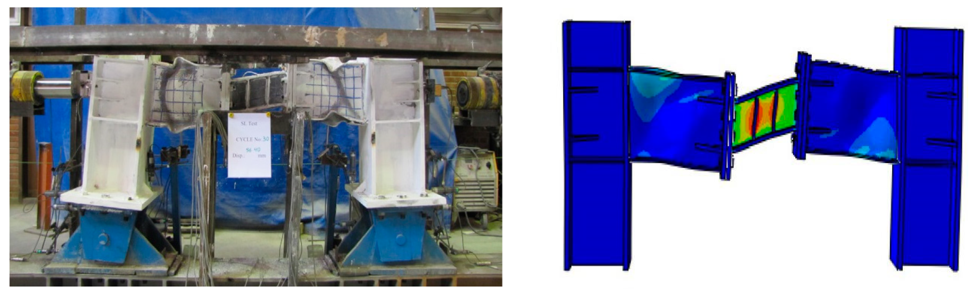
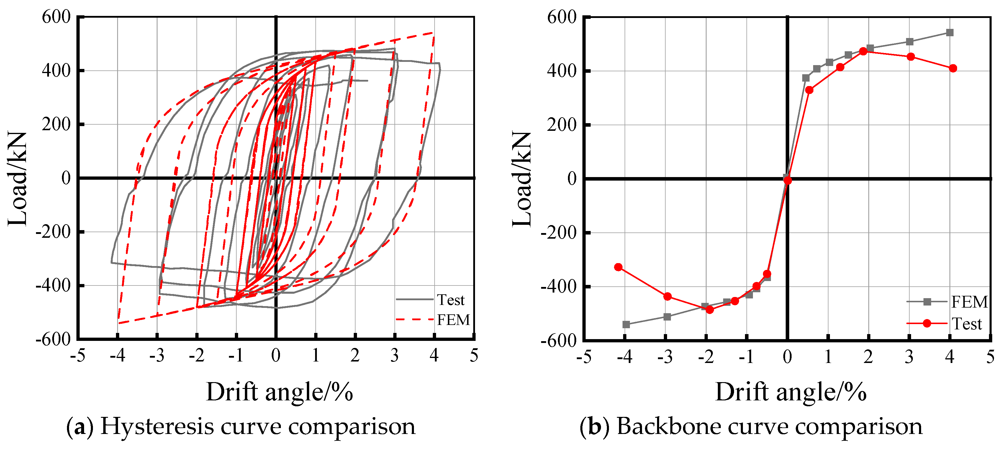
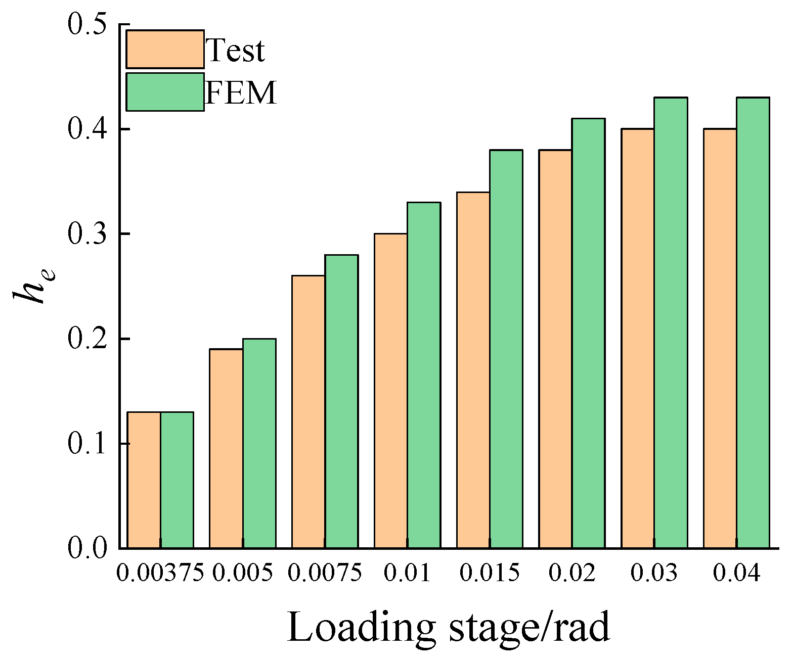
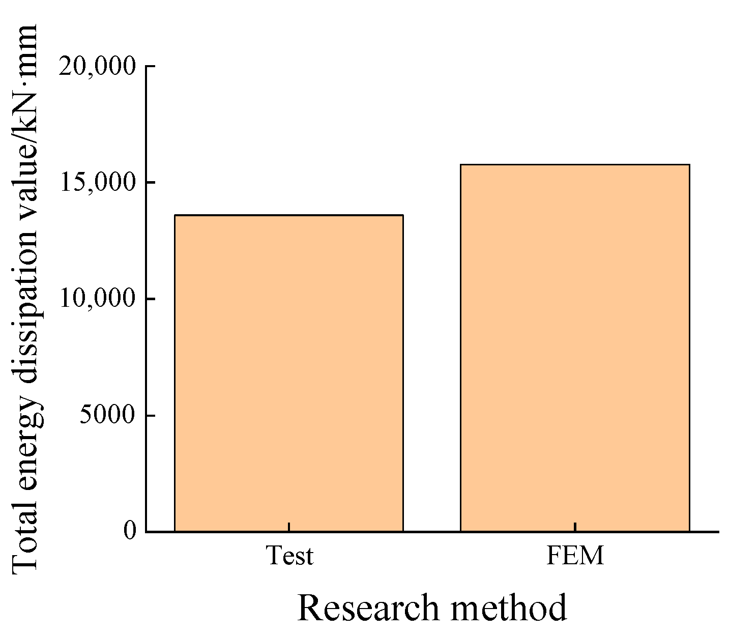
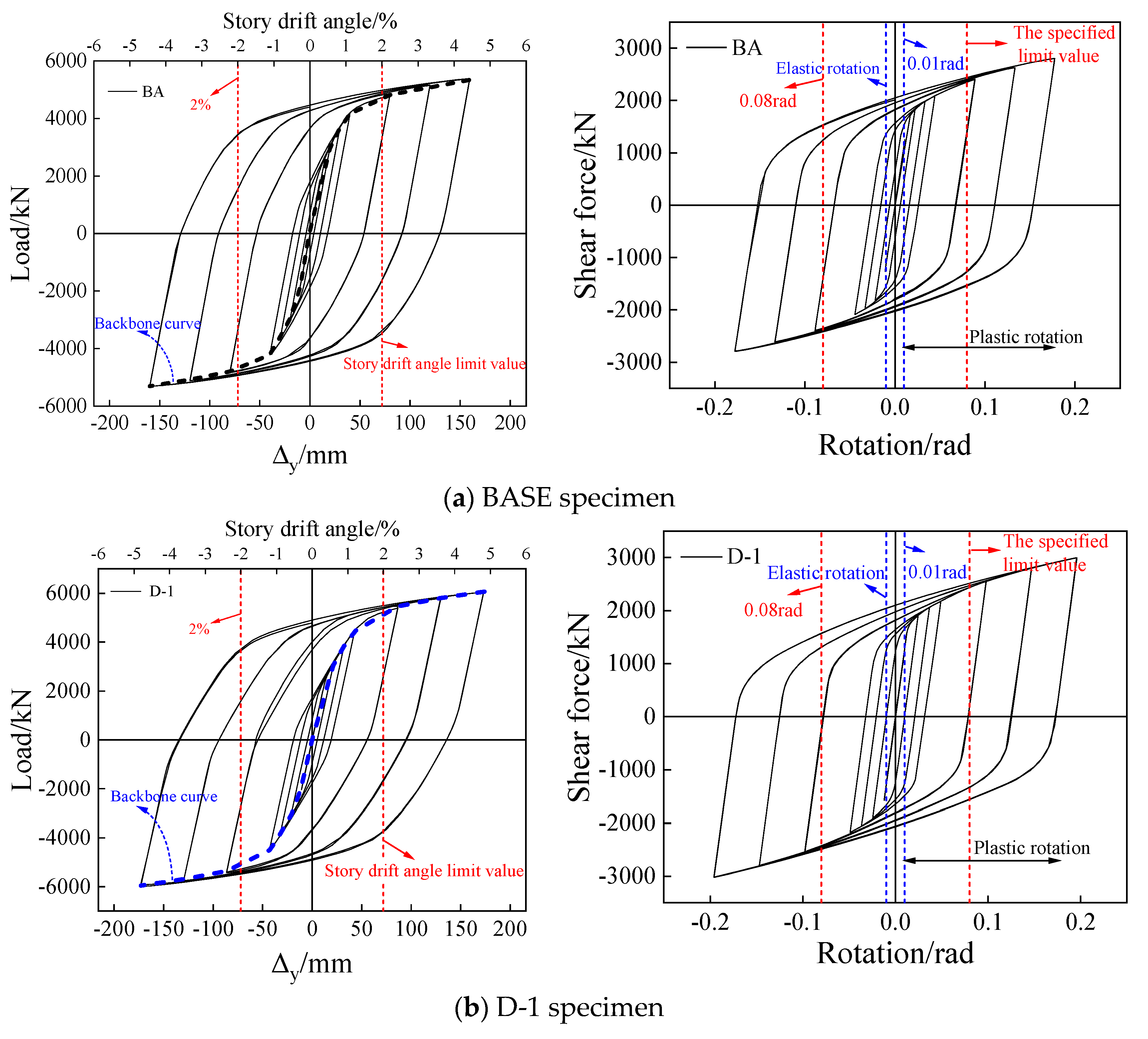
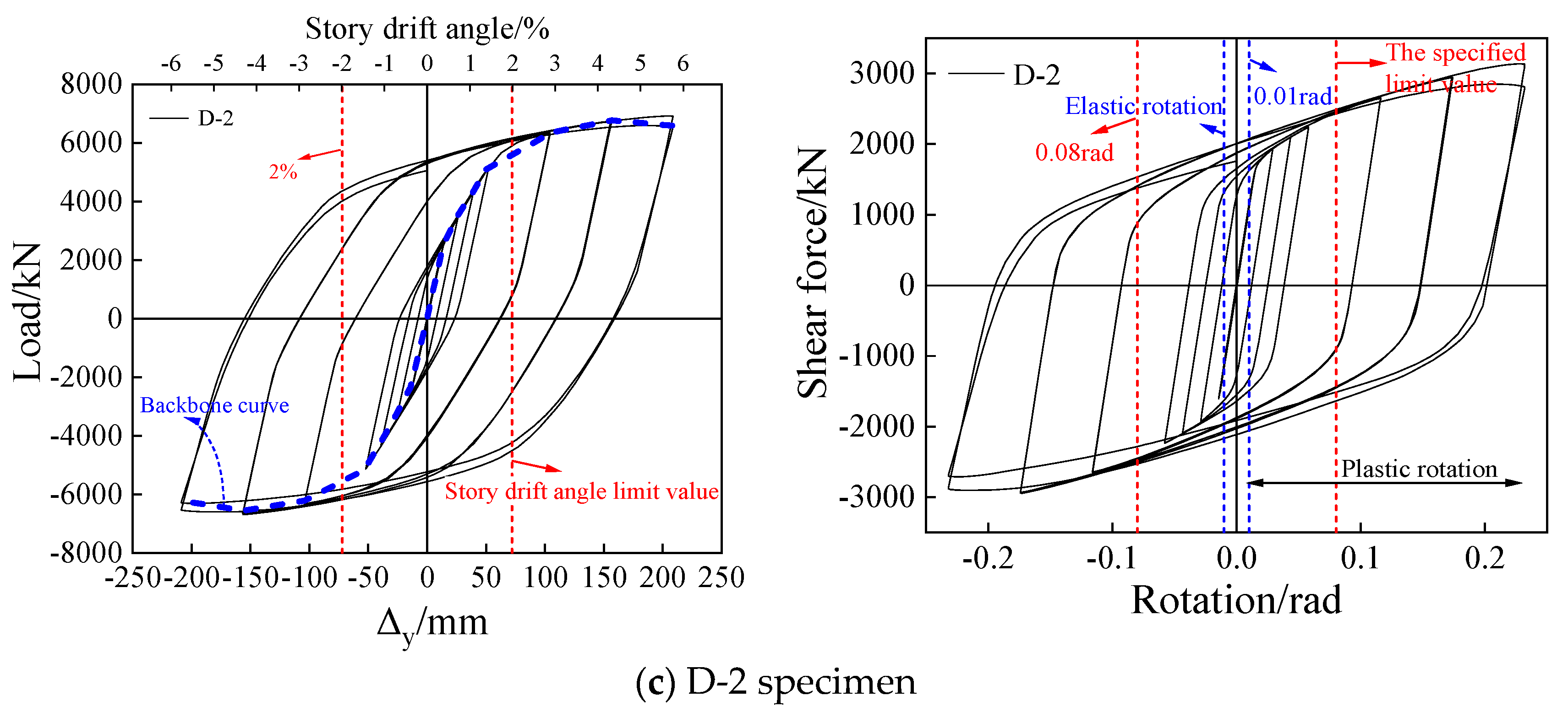
2.4. Comparison of Finite Element Simulation and Test Results

The comparison between the test results and the finite element simulation of the overall structural failure is depicted in Figure 6. During testing, shear failure occurred in the link, while varying degrees of buckling were observed in the flanges and web of the frame beam. The finite element simulation results indicate that plastic failure was primarily concentrated in the link, with significant deformation also occurring in the flanges and web of the frame beam. However, due to disparities in the weakening degree between the finite element model and actual specimen for the frame beam flanges, pronounced buckling observed during experimentation was not replicated by the finite element model. Nevertheless, this disparity does not compromise the reliability of the finite element simulation. In the ultimate state conditions, complete elasticity was maintained by the frame columns, while the end plates connected via high-strength bolts exhibited no signs of failure, thus demonstrating feasibility for high-strength bolted end plate connections.
The hysteresis curve obtained from the finite element simulation, as illustrated in Figure 7, presents a more comprehensive profile compared with the experimental curve. Notably, the cyclic curves in the simulation exhibited remarkable coincidence without displaying any pinching phenomena under identical displacements. Compared with the experimental curves, the finite element simulation hysteresis curves are more robust and exhibit no pinching phenomena, with the cyclic curves nearly overlapping at the same displacement levels. The experimental peak loads were 473 kN and −486 kN, while the finite element simulation peak loads were 484 kN and −473 kN, resulting in errors of 2.32% and −2.67%, respectively. After reaching the peak load, the experimental bearing capacity gradually declined. In contrast, after the initial stiffness degradation in the finite element simulations, the increase in bearing capacity became gradually more stable without a subsequent decline. This discrepancy is attributed to the chosen material constitutive model in the finite element analysis, which did not incorporate load failure; the bearing capacity would only decrease when the structure transformed into a mechanism. Although this slightly deviates from real-world behavior, it does not affect the validity of the finite element analysis method.
As illustrated in Figure 8 and Figure 9 and Table 3 and Table 4, both the energy dissipation and equivalent viscous damping coefficient (he) of the tested structures and finite element models exhibited an increasing trend with respect to the story drift angle. Upon reaching link yielding, a transition into a plastic phase occurred, resulting in a significantly expanded hysteresis curve and consequently a larger hysteresis loop area. The total energy dissipation value for the finite element simulation curve was recorded to be 13,596.96 kN·mm, while that of the experimental curve amounted to 15,769.97 kN·mm. Comparative analysis revealed that the finite element simulation demonstrated a superior energy dissipation capability by exhibiting a larger hysteresis loop area compared with the experimental observations. Notably, the high-strength bolted end plates demonstrated remarkable effectiveness in dissipating energy through link connections. Following an earthquake event, repair or replacement of damaged links can be easily accomplished by simply dismantling these high-strength bolts, thereby facilitating post-earthquake repairs while simultaneously reducing the costs associated with manpower, materials, and financial resources.

3. Finite Element Model Parameter Design

The components in this study were modeled using three-dimensional solid modeling techniques. The structural model employed the linear reduced-integration element C3D8R for finite element simulation. Figure 10 illustrates the geometric dimensions of the BASE specimen, which had a height of 3600 mm and a span of 7200 mm. The replaceable link measured 900 mm in length, with an energy-dissipating region spanning 550 mm. Table 5 provides details on the cross-sectional dimensions and steel grades of the BASE specimen. A total of four groups comprising nine specimens were designed for this study. A refined model was established using the finite element software ABAQUS, incorporating the relevant parameters listed in Table 6. The L series encompassed variations in the length of the energy-dissipating region among the specimens; the D series introduced alterations to the steel grade; the K series modified the span; and finally, the H series changed the length of the link.
The stress–strain relationship of the steel was established based on the isotropic Mises yield criterion and kinematic hardening rule, while tie constraints were applied between the supports, frame beams, and frame columns. The high-strength bolt heads and nuts interacted with the flanges of the frame beams and end plates, the bolt rods interacted with the walls of the bolt holes, and the end plates interacted with the other end plates and flanges of the frame beams. Loading was imposed by constraining the X-direction displacement (X = 0) of the frame columns to prevent out-of-plane instability. Column constraints, vertical loads, and horizontal loads were applied using a node-to-surface coupling method. The boundary conditions are illustrated in Figure 11.
The stress–strain relationship of the steel utilized in this section was simplified to a tri-linear model, as illustrated in Figure 12. By employing the isotropic Mises yield criterion and kinematic hardening rule provided by the ABAQUS software, an isotropic, nonlinear mixed hardening elastoplastic constitutive relationship was established.
The application of loads was divided into three main categories: bolt load application, vertical load application, and horizontal load application. Prior to applying the bolt load, an “internal” surface had to be created at the location of the bolt. To prevent non-convergence due to excessive force applied all at once, a small force was initially applied to establish contact between the bolt and the connected components. This initial force was then replaced with the intended preload before adjusting the load to fix the current length of the bolt(s). The vertical load was applied as a force with the magnitude set to 0.2 Ny (where Ny represents the axial pressure when full cross-section yield occurred in the column). In order to more accurately simulate real conditions, the large deformation option was enabled.
The horizontal load was applied using displacement control. For monotonic loading, the load was incrementally increased until structural failure occurred. In the case of cyclic loading, the load was systematically applied in multiples of the yield displacement, following a pattern of ∆y/4, ∆y/2, 3∆y/4, ∆y, 2∆y, 3∆y, 4∆y, and so on. Each displacement level was cycled twice before progressing to the next level until structural failure ensued.
According to the actual loading conditions of the eccentrically braced steel frame, three failure criteria were established during the loading process. If any one of these criteria was met, then this indicated structural failure, and the loading was terminated:
(1)
The stress in the link reached the ultimate stress of the material.
(2)
The plastic strain in the high-strength bolts reached the ultimate strain of the material.
(3)
The stress at any cross-section of the frame beams, columns, or other components reached the yield stress, resulting in plastic hinge formation.

4. Analysis of Specimen Parameters

4.1. Analysis of Finite Element Results for D-Series Specimens

4.1.1. Hysteresis Curve Analysis of D-Series Specimens

The structure underwent cyclic loading, and the resulting hysteresis curves are presented in Figure 13. Both the BASE specimen and D series specimens exhibited complete hysteresis curves with a spindle shape while completing a 4∆y displacement cycle. This indicates that the high-strength steel frame-Y-shaped eccentrically braced frame structure with replaceable links possessed an excellent seismic energy absorption capability and strong plastic deformation ability. Prior to link yielding, the structure remained in an elastic stage, displaying a linear hysteresis curve during repeated loading cycles without significant stiffness degradation. After link yielding occurs and enters into the plastic phase, the hysteresis curve starts exhibiting loop shapes. With increasing displacement, its area enlarges along with more apparent plastic deformation. Meanwhile, the stiffness significantly decreases, while the bearing capacity gradually levels off.

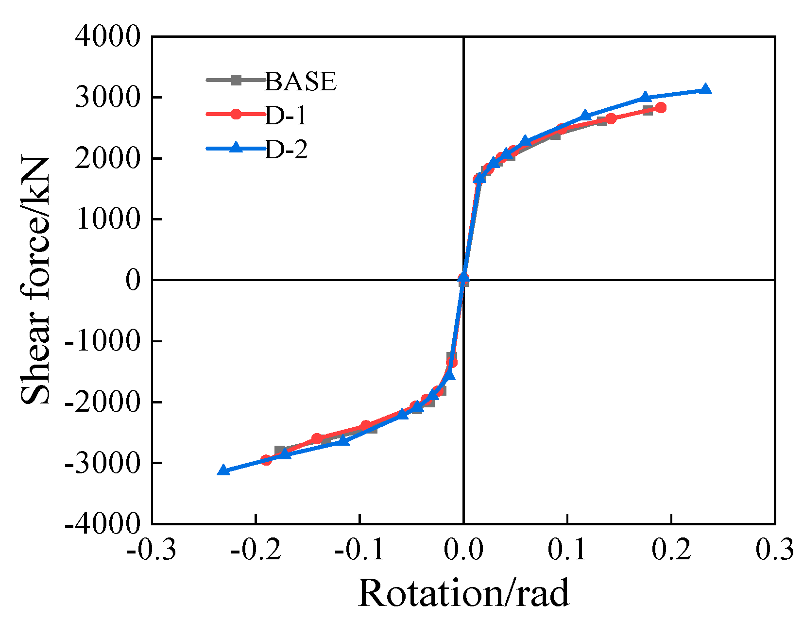
4.1.2. Analysis of Bearing Capacity, Plastic Rotation and Ductility of D-Series Specimens

The backbone and shear–rotation curves of the links are depicted in Figure 14 and Figure 15, respectively. The ultimate bearing capacities of the BASE, D-1, and D-2 specimens were determined to be 4255.4 kN, 4470.3 kN, and 5018.5 kN, respectively. A discernible increasing trend in the ultimate bearing capacity was observed with higher steel grades. Compared with the BASE specimen, the D-1 and D-2 specimens exhibited increments in their ultimate bearing capacities of 6.9% and 20.7%, respectively. Notably, all specimens demonstrated significantly excessive plastic rotations for the links (0.18 rad for the BASE specimen; 0.19 rad for the D-1 specimen; and 0.23 rad for the D-2 specimen), surpassing the specified plastic rotation limit of 0.08 rad as stipulated by American seismic design code AISC341-16 [22] for shear-yielding links.
The maximum shear forces experienced by the links in each specimen were as follows: BASE = 2747.3 kN; D-l = 2954.9 kN; and D-2 = 3135.1 kN. Consistent with the overall performance, there was an increasing trend observed in the ultimate shear force with higher steel grades. In comparison with the BASE specimen, both the D-l and D-2 specimens exhibited significantly higher ultimate shear forces of 7.6% and 14.l%, respectively. Moreover, these specimens demonstrated exceptional ductility properties along with a robust capacity for plastic deformation.

4.1.3. Failure Mode of D-Series Specimens

The plastic strain cloud diagram of the BASE specimen at the ultimate state is depicted in Figure 16a. The distribution of equivalent plastic strain predominantly concentrated within the energy-dissipating region, aligning with design expectations despite relatively high stress on the upper flange. The central portion of the link effectively absorbed and dissipated seismic energy, satisfying the design requirements for variable cross-section links. At the ultimate state, the stress in the energy-dissipating region reached its maximum level. Once compromised, the link serves as a primary line of defense, while the frame beam acts as a secondary line of seismic defense.
The plastic strain cloud diagrams of the D-series specimens at the ultimate state are depicted in Figure 17a and Figure 18a. These diagrams exhibit a failure mode similar to that observed in the BASE specimen. Furthermore, elevated stress levels can be observed in the frame beams and supporting flanges connected to the links, as well as in the top and bottom sections of the frame columns, accompanied by plastic failure occurring within the energy-dissipating region. However, an increase in the steel grade led to a gradual reduction in the stress experienced by these areas. This suggests that higher strength grades of steel diminish the participation of frame components in energy dissipation, thereby enhancing performance within designated energy-dissipating regions.

4.2. Analysis of Finite Element Results for L-Series Specimens

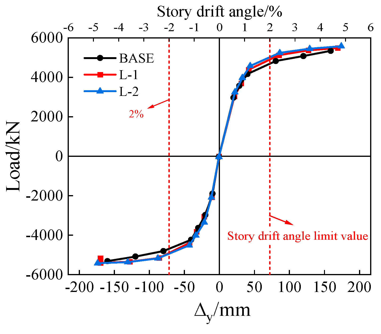
4.2.1. Hysteresis Curve Analysis of L-Series Specimens

The structure was subjected to cyclic loading, and the resulting hysteresis curves are illustrated in Figure 19. The hysteresis curves of the L-series specimens exhibited a spindle shape and demonstrated significant completeness. During the elastic stage, the curves predominantly display linear behavior. As the links yield, stiffness degradation is initiated. With increasing displacement, the trend of an enhanced bearing capacity becomes less pronounced. However, upon reaching a load level of 4∆y, a decline in the bearing capacity can be observed for the second loop of the hysteresis curve. This decline can be attributed to both plastic deformations occurring within the frame and yielding of the end plates connecting the frame beams at 4∆y.

4.2.2. Analysis of Bearing Capacity, Plastic Rotation, and Ductility of L-Series Specimens

The backbone and shear–rotation curves of the links for the specimens are illustrated in Figure 20 and Figure 21, respectively. As shown in Figure 20, the ultimate bearing capacities of the BASE, L-1, and L-2 models were recorded to be 5393.61 kN, 5449.29 kN, and 5566.73 kN, respectively. In comparison with the BASE specimen, the L-1 and L-2 specimens demonstrated increases in their ultimate bearing capacities of 1.1% and 3.2%, respectively. It can be observed that reducing the length of the energy-dissipating region enhanced the overall structural ultimate bearing capacity.
In the finite element simulation, the plastic rotation of the link was induced by shear deformation in the energy-dissipating region. As illustrated in Figure 21, the shear–rotation curves for the links show no discrepancies in the plastic rotations during the elastic stage across all models. However, upon entering the plastic stage, it can be observed that the L-2 model exhibited a significantly accelerated development of plastic rotation and reached its maximum value at the ultimate state. The plastic rotations for the L-series links measured 0.178 rad, 0.187 rad, and 0.193 rad, significantly surpassing the limit of 0.08 rad. The ultimate shear forces for the BASE specimen and L-1 and L-2 specimens were recorded to be 2747.3 kN, 2874.9 kN, and 2975.13 kN, respectively, thus indicating increases of approximately 4.6% and 8.3% in the ultimate shear forces for the L-1 and L-2 specimens compared with the BASE specimen, respectively.
Furthermore, it can be observed that as the length of the energy-dissipating region decreased, there was a minor yet discernible increasing trend in the ultimate shear force exhibited by the links.

4.2.3. Failure Mode of L-Series Specimens

The plastic strain cloud diagrams of all of the L-series specimens at the ultimate state and the plastic strain distribution diagrams of the replaceable links are illustrated in Figure 22 and Figure 23, respectively. In the L-series specimens, the plastic strain was predominantly concentrated in the regions associated with energy dissipation. Stress concentrations were observed on the right side of the lower flange of the frame beam connected to the link and on the supporting flange. The shorter length of these energy-dissipating regions led to more pronounced stress concentration. After completing a cyclic displacement of 4∆y, minimal deformation was observed in both end plates of the links within the L-series specimens, indicating their complete elastic behavior throughout this displacement range. Specifically, for specimen L-1, no plasticity occurred even at 4∆y, whereas for specimen L-2, elastic behavior persisted until 3∆y before transitioning into a plastic stage at 4∆y. Despite minor plastic deformation occurring during testing, all replaceable links met their design requirements.

4.3. Analysis of Finite Element Results for K-Series Specimens

4.3.1. Hysteresis Curve Analysis of K-Series Specimens

The hysteresis curves obtained from cyclic loading of the structure are depicted in Figure 24. It is evident that the hysteresis curves of the K-series specimens exhibit a spindle shape and demonstrate significant completeness. Prior to the yielding of the links, the hysteresis curves of the specimens display essentially linear behavior. Subsequently, as plastic deformation occurs in the links, loops start to form within the hysteresis curves, with their size enlarging and the area increasing with the displacement increments. The trend of an increasing bearing capacity gradually diminished as the displacement increased further. Moreover, reducing the span led to an enhancement in the structural bearing capacity while accentuating the plastic deformation.

4.3.2. Analysis of Bearing Capacity, Plastic Rotation, and Ductility of K-Series Specimens

The backbone curves and shear–rotation curves of the links are presented in Figure 25 and Figure 26, respectively. It is evident from the figures that all specimens exhibited high ductility coefficients, indicating exceptional structural ductility and a proficient plastic deformation capability. A reduction in span led to a significant enhancement in structural ductility. As depicted in Figure 25, the backbone curves demonstrate that as the displacement increased, the trend of augmenting the structural bearing capacity gradually diminished, resulting in a decrease in the slope of the backbone curve. Furthermore, decreasing the frame span resulted in an increase in the structural bearing capacity.
According to Figure 26, the shear–rotation curves of the links indicate that during the elastic stage, there was no significant disparity in plastic rotation among the models. However, upon entering the plastic stage, it can be observed that the K-2 model exhibited a notably accelerated development of plastic rotation in the link, reaching its maximum rotation at the ultimate state. The plastic rotations of the links in the K series were significantly higher, with values of 0.178 rad, 0.188 rad, and 0.195 rad, surpassing 0.08 rad by a considerable margin. The ultimate shear forces for the links in the BASE specimen, K-1 specimen, and K-2 specimen were recorded to be 2747.3 kN, 2874.9 kN, and 2975.13 kN, respectively, representing increases of approximately 4.6% and 8.3% for specimens K-1 and K-2 compared with the BASE specimen, respectively. Moreover, it can be observed that with a reduction in the span length, there existed an ascending trend in the ultimate shear force for the links, albeit with minimal differences.

4.3.3. Failure Mode of K-Series Specimens

The plastic strain cloud diagrams of the K-series specimens at their ultimate states are presented in Figure 27a and Figure 28a. These diagrams exhibit a failure mode similar to that observed in the BASE specimen, where plastic failure initially occurs within the energy-dissipating region before propagating to the frame beam, indicating an ideal failure mechanism. The stress distributions in the replaceable links of both the BASE specimen and K-series specimens under different cycles are depicted in Figure 27b and Figure 28b. It is evident from these figures that plastic strain primarily accumulated within the energy-dissipating region, with a greater concentration observed specifically for the K-2 specimen, suggesting enhanced efficiency of energy dissipation.

4.4. Analysis of Finite Element Results for H-Series Specimens

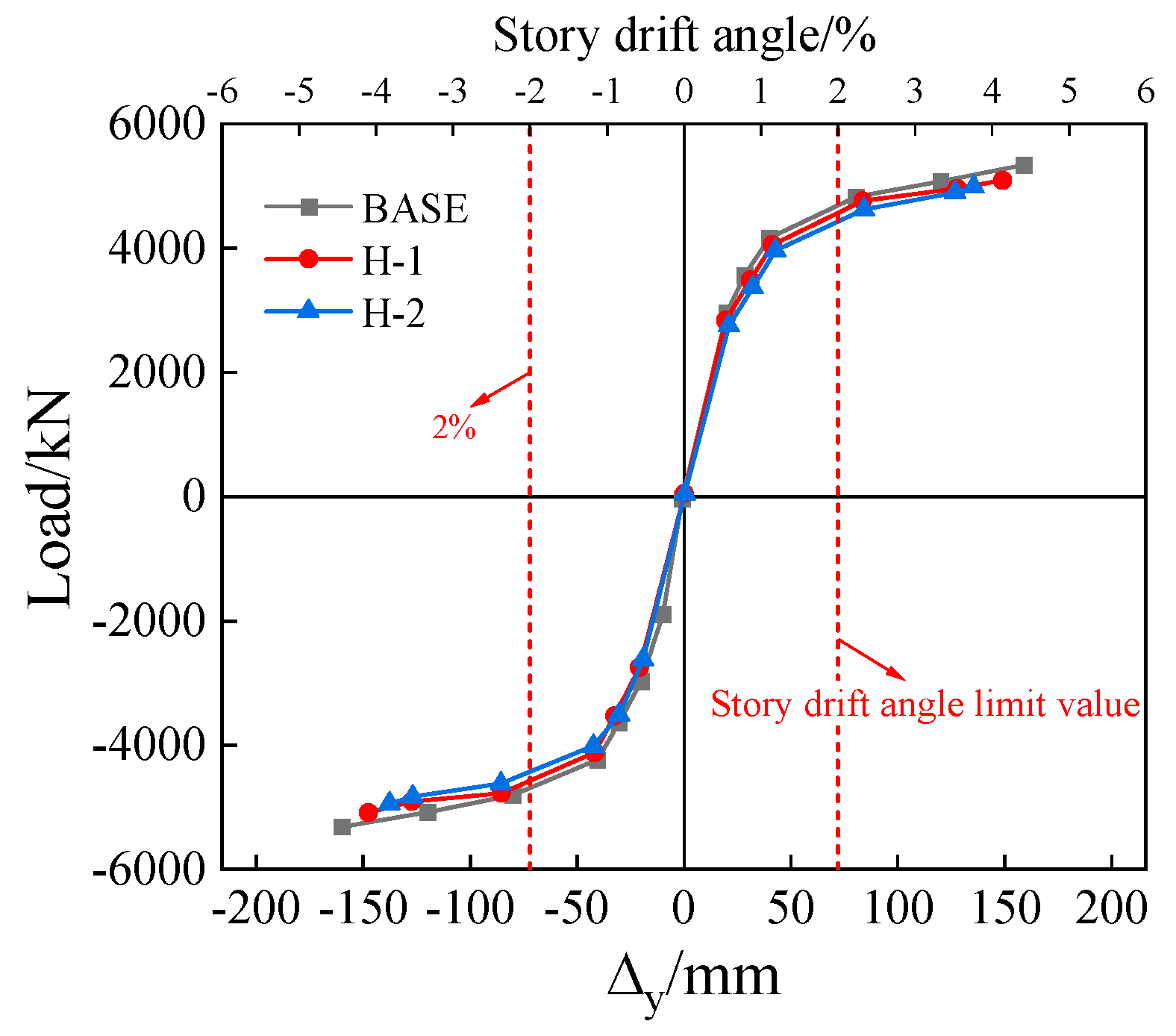
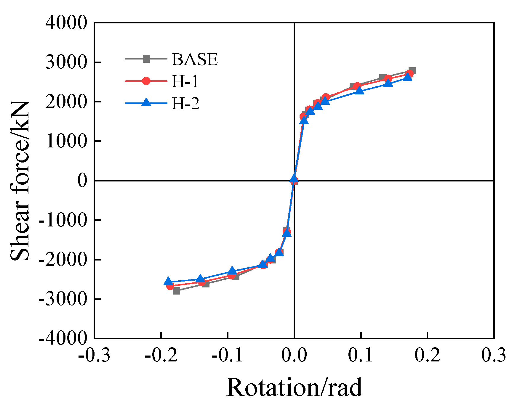
4.4.1. Hysteresis Curve Analysis of H-Series Specimens

The hysteresis curves of the H-series specimens are illustrated in Figure 29, presenting a comprehensive profile and exhibiting a trend similar to that observed in the L series. With an increase in link length, there was a corresponding reduction in the structural bearing capacity. Upon reaching a story drift angle of 0.02 rad, the growth rate of the horizontal bearing capacity for each specimen tended to stabilize. In subsequent stages, the bearing capacity experienced decline during the second cycle due to frame buckling and yielding of the end plates connecting the link and frame beam, resulting in plastic deformation.

4.4.2. Analysis of Bearing Capacity, Plastic Rotation, and Ductility of H-Series Specimens

Figure 30 and Figure 31 depict the backbone curve and shear force–rotation curve of the energy dissipation link, respectively. It can be observed from Figure 30 that the yield bearing capacities of the BASE, H-1, and H-2 specimens were 4255.4 kN, 4178.2 kN, and 4032.7 kN, respectively. The H-1 and H-2 specimens exhibited reductions of 1.81% and 5.23%, respectively, compared with the BASE specimen. In addition, the ultimate bearing capacities of the BASE, H-1, and H-2 specimens were 5393.61 kN, 5009.29 kN, and 4946.31 kN, respectively, showing differences of 7.13% and 8.29% for the H-1 and H-2 specimens compared with the BASE specimen, respectively. These results indicate that variations in the length of the energy dissipation link significantly influenced the ultimate bearing capacity. All specimens demonstrated high ductility coefficients, reflecting excellent structural plastic deformation capabilities. As the length of the energy dissipation link increased, the ductility of the structure improved. However, there was a notable decrease in the ultimate bearing capacity.
The shear force–rotation curve of the links in Figure 31 indicates that there was no difference in the plastic rotations of the links among the models during the elastic stage. However, once the plastic stage was reached, the rotation of the BASE specimen exhibited a significantly faster increase and reached its highest value at the ultimate state. The plastic rotations of the H-series links were measured to be 0.178 rad, 0.173 rad, and 0.170 rad, which significantly exceed the limit of 0.08 rad. The ultimate shear forces for the BASE, H-1, and H-2 specimens were recorded to be 2747.3 kN, 2703.96 kN, and 2664.57 kN, respectively. In comparison with the ultimate shear force value of the BASE specimen, both the H-1 and H-2 specimens exhibited decreases of approximately 1.57% and 3.1%, respectively, in their respective values for the ultimate shear forces observed. Although all specimens demonstrated plastic rotations far exceeding the limit, set to 0.08 rad, it can be concluded that longer link lengths ultimately resulted in lower bearing capacities, along with reduced levels of achieved plastic rotation. This observation suggests that excessively long links do not contribute favorably toward energy dissipation within structural systems.

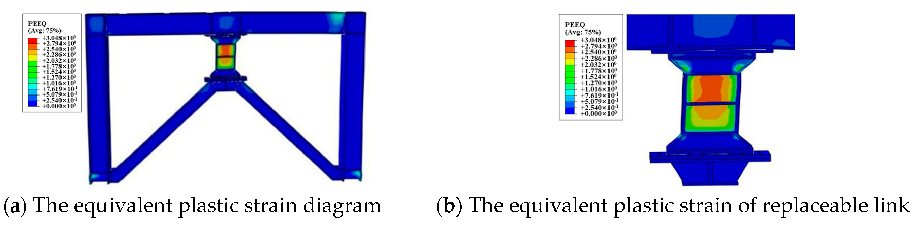
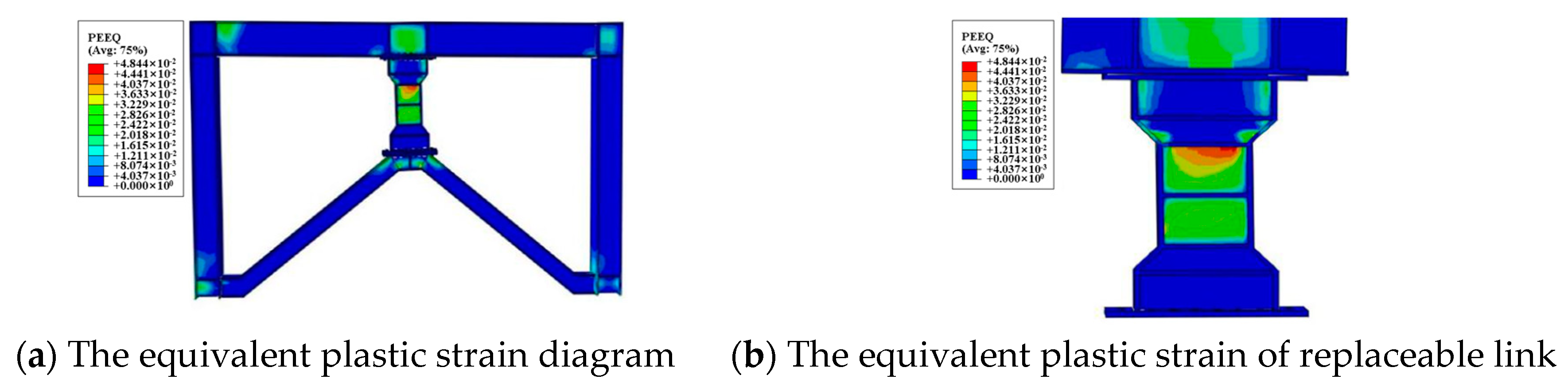
4.4.3. Failure Mode of H-Series Specimens

Figure 32 and Figure 33 illustrate the plastic strain distribution diagrams for the entire specimen and the replaceable link, respectively, under the ultimate conditions for the H-series specimens. The figures demonstrate that the plastic strain was predominantly concentrated in the energy-dissipating region. However, significant levels of plastic strain were also observed in the frame beams, supporting flanges, webs connected to the link, as well as in the top and bottom sections of the frame columns. In the case of the H-1 specimen, although the elastic behavior was retained by the flange end plate of the frame beam after completing a cyclic displacement of 4Δy, yielding occurred on both sides of this end plate from 1Δy to 4Δy. This observation suggests that replacement might pose challenges under severe seismic conditions. Consequently, despite achieving a displacement amplitude of 4Δy for the H-series specimens, both end plates connected to the frame beams and the support frame beams linked to the replaceable links experienced yield and entered into a plastic stage during the ultimate conditions. Such behavior failed to meet the requirements for replaceable links, and this highlights how significantly the link length influences structural hysteretic performance, with excessive lengths being detrimental to concentrated energy dissipation.

5. Conclusions

The present study employed the BASE specimen to develop four groups of Y-shaped eccentric braced steel frame models, incorporating variations in the length of the energy-dissipating region and the combination of the steel strength, link length, and span. By conducting finite element analysis using ABAQUS software, this research investigated the influence of these parameters on the seismic performance of the models subjected to cyclic loading. The key findings are summarized as follows:
(1)
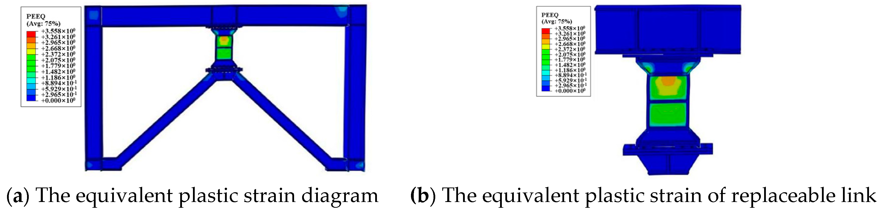
The BASE specimen demonstrated that a Y-shaped eccentrically braced steel frame with high-strength steel replaceable links effectively dissipated energy. Under horizontal loading, plastic strain primarily occurred in the energy-dissipating region. In the ultimate conditions, both the beams and columns underwent plastic deformation, thereby validating the performance-based design.
(2)
For the structures incorporating different steel combinations, plastic strain was predominantly localized within the energy-dissipating region. Utilizing higher-grade steel for beams, columns, and end plates enhanced the plastic strain concentration in the energy-dissipating beam segment while reducing it in the non-energy-dissipating components, thereby facilitating easier replacement of links following seismic events.
(3)
The specimens demonstrated exceptional ductility, with enhanced load-bearing capacity and ductility observed as the span length decreased.
(4)
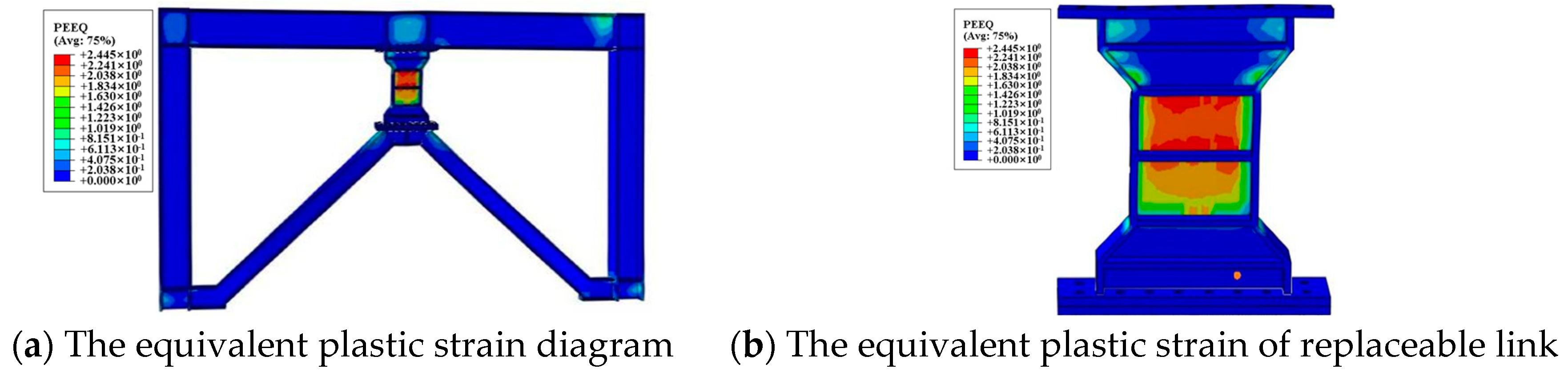
The plastic strain was primarily concentrated in the energy-dissipating region, while stress was predominantly localized on the lower flange of the frame beam connected to the link. Shorter energy-dissipating regions enhanced both the ductility and load-bearing capacity. However, they also resulted in increased plastic rotation within the link. The flange end plates of the frame beam underwent limited plastic deformation, thereby allowing for potential replacement of the link.
(5)
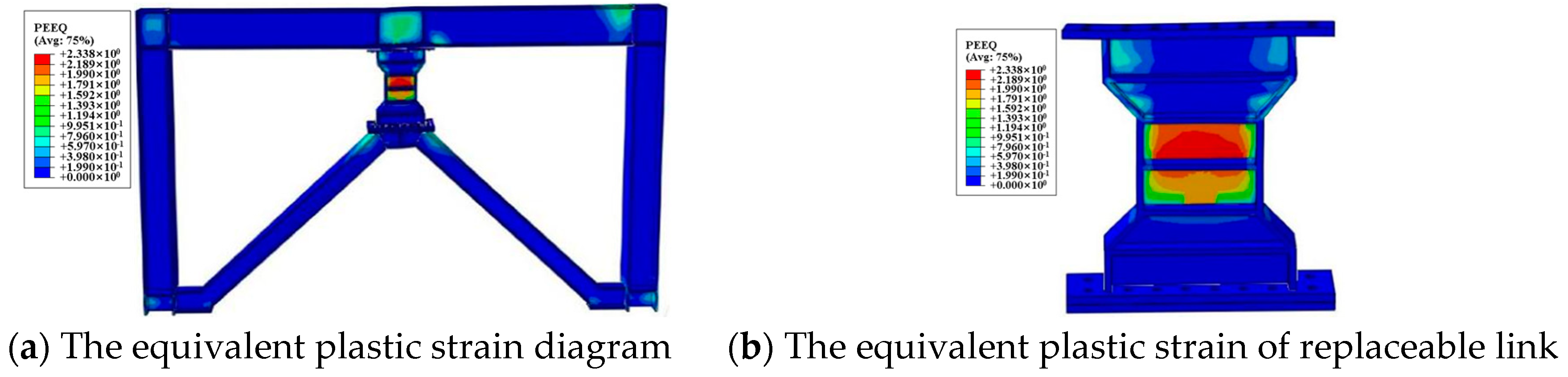
The reduction in the plastic rotation and load-carrying capacity, resulting from an increase in the link length, hampered effective energy dissipation and complicated link replacement following strong seismic events. An excessive link length can induce flange buckling, impeding efficient energy dissipation.
The proposed Y-shaped eccentrically braced steel frame structure, which integrates replaceable links and high-strength steel, is based on comprehensive research. Extensive investigations have been conducted to evaluate its seismic performance. However, further research is warranted in the following areas:
(1)
This study primarily employed the finite element method to analyze the seismic behavior of the new Y-shaped eccentrically braced structure. Due to various factors influencing the computational process, there may be fluctuations in the accuracy of the simulation results. Hence, additional experimental research is necessary.
(2)
This study only considered four parameters which affect structural seismic performance. Future research could explore other influential factors.

Author Contributions

Conceptualization, S.L.; methodology, X.C. and S.L.; software, M.H.; investigation, X.C.; data curation, X.C.; writing—original draft preparation, X.C.; writing—review and editing, S.L. and M.H.; project administration, G.L.; funding acquisition, G.L.; supervision, G.L. All authors have read and agreed to the published version of the manuscript.

Funding

The authors are grateful for the financial support from the Postdoctoral Research Foundation of China (2022M712562) and National Key Research and Development Plan (YS2022YFB2600177).

Data Availability Statement

The original contributions presented in the study are included in the article, further inquiries can be directed to the corresponding author.

Conflicts of Interest

The authors declare that they have no known competing financial interests or personal relationships that could have appeared to influence the work reported in this paper. All authors declare that no conflict of interest exists.

References

  1. Li, T.; Su, M.; Guo, J.; Zhao, K.; Zhang, Q. Seismic performance evaluation of Y-shaped eccentric brace–high-strength steel frame structure based on remote collaborative hybrid test. Soil Dyn. Earthq. Eng. 2023, 164, 107621. [Google Scholar] [CrossRef]
  2. GB50011-2010; Code for Seismic Design of Buildings. China Architecture and Building Press: Beijing, China, 2016.
  3. Keivan, A.; Zhang, Y. Nonlinear seismic performance of Y-type self-centering steel eccentrically braced frame buildings. Eng. Struct. 2019, 179, 448–459. [Google Scholar] [CrossRef]
  4. Ma, X.; Zhang, X.; Zhang, S.; Zhao, G.; Dong, B. Seismic performance of very short links in eccentrically braced substructures. J. Constr. Steel Res. 2024, 216, 108628. [Google Scholar] [CrossRef]
  5. Li, S.; Xu, T.; Li, X.; Liang, G.; Xi, H. Elastic stiffness and bearing mechanism of eccentrically braced steel frames. Structures 2023, 55, 818–833. [Google Scholar] [CrossRef]
  6. Zheng, X.-W.; Li, H.-N.; Gardoni, P. Hybrid Bayesian-Copula-based risk assessment for tall buildings subject to wind loads considering various uncertainties. Reliab. Eng. Syst. Saf. 2023, 233, 109100. [Google Scholar] [CrossRef]
  7. Zheng, X.-W.; Li, H.-N.; Shi, Z.-Q. Hybrid AI-Bayesian-based demand models and fragility estimates for tall buildings against multi-hazard of earthquakes and winds. Thin-Walled Struct. 2023, 187, 110749. [Google Scholar] [CrossRef]
  8. Zheng, X.-W.; Li, H.-N.; Lv, H.-L.; Huo, L.-S.; Zhang, Y.-Y. Bayesian-based seismic resilience assessment for high-rise buildings with the uncertainty in various variables. J. Build. Eng. 2022, 51, 104321. [Google Scholar] [CrossRef]
  9. Zheng, X.-W.; Li, H.-N.; Gardoni, P. Probabilistic seismic demand models and life-cycle fragility estimates for high-rise buildings. ASCE-J. Struct. Eng. 2021, 147, 04021216. [Google Scholar] [CrossRef]
  10. Lettieri, A.; de la Peña, A.; Freddi, F.; Latour, M. Damage-free self-centring links for eccentrically braced frames: Development and numerical study. J. Constr. Steel Res. 2023, 01, 107727. [Google Scholar] [CrossRef]
  11. Almasabha, G.; Al-Mazaidh, R. Simple Truss Model to estimate the shear strength of short links in the ccentrically Braced Frame (EBF) steel system. Thin-Walled Struct. 2023, 188, 110811. [Google Scholar] [CrossRef]
  12. Yin, Z.; Yang, B.; Zhang, X. Design of an eccentrically buckling-restrained braced steel frame with web-bolted replaceable links. J. Constr. Steel Res. 2022, 192, 107250. [Google Scholar] [CrossRef]
  13. Montuori, R.; Nastri, E.; Piluso, V. Theory of plastic mechanism control for eccentrically braced frames with inverted y-scheme. J. Constr. Steel Res. 2014, 92, 122–135. [Google Scholar] [CrossRef]
  14. Valente, M.; Castiglioni, C.A.; Kanyilmaz, A. Dissipative devices for earthquake resistant composite steel structures: Bolted versus welded solution. Bull. Earthq. Eng. 2016, 14, 3613–3639. [Google Scholar] [CrossRef]
  15. Vasdravellis, G.; Valente, M.; Castiglioni, C.A. Dynamic response of composite frames with different shear connection degree. J. Constr. Steel Res. 2009, 65, 2050–2061. [Google Scholar] [CrossRef]
  16. Tratan, A.; Dubina, D.; Dinu, F. Control of Global Performance of Seismic Resistant EBF with Removal Link. In Proceedings of the Conference on Behavior of Steel Structures in Seismic Aeas, STESSA, Naples, Italy, 9–12 June 2023; pp. 455–461. [Google Scholar]
  17. Stratan, A.; Dubina, D. Bolted Links for Eccentrically Braced Steel Frames. In Proceedings of the Fifth International Workshop on Connections in Steel Structures, Delft, The Netherlands, 3–4 June 2004; Volume 3, pp. 223–232. [Google Scholar]
  18. Shayanfar, M.A.; Rezaeian, A.R.; Zanganeh, A. Seismic performance of eccentrically braced frame with vertical link using PBPD method. Struct. Des. Tall Spec. Build. 2014, 23, 1–21. [Google Scholar] [CrossRef]
  19. Li, S.; Su, M. A performance-based seismic design method for eccentrically braced steel frames. Eng. Mech. 2014, 31, 195–204. [Google Scholar] [CrossRef]
  20. Mahmoudi, F.; Dolatshahi, K.M.; Mahsuli, M.; Nikoukalam, M.T.; Shahmohammadi, A. Experimental study of steel moment resisting frames with shear link. J. Constr. Steel Res. 2019, 154, 197–208. [Google Scholar] [CrossRef]
  21. Kaufmann, E.; Metrovich, B.; Pense, A. Characterization of Cyclic Inelastic Strain Behavior on Properties of A572 Gr. 50 and A913 Gr. 50 Rolled Sections; ATLSS Rep, Lehigh University: Bethlehem, PA, USA, 2001. [Google Scholar]
  22. ANSI/AISC 341-16; Seismic Provision for Structure Steel Buildings. American Institute of Steel Construction: Chicago, IL, USA, 2016.
Figure 1. Schematic diagram of replaceable link (mm).
Buildings 14 02149 g001
Figure 2. Loading protocol.
Buildings 14 02149 g002
Figure 3. Mesh generation.
Buildings 14 02149 g003
Figure 4. Contact settings.
Buildings 14 02149 g004
Figure 5. Typical buckling modes of finite element mode.
Buildings 14 02149 g005
Figure 6. Failure modes for specimen.
Buildings 14 02149 g006
Figure 7. Comparison of hysteretic loading results.
Buildings 14 02149 g007
Figure 8. Comparison of equivalent viscous damping coefficients.
Buildings 14 02149 g008
Figure 9. Comparison of total dissipated energy of specimen.
Buildings 14 02149 g009
Figure 10. Dimensions of the structures (mm).
Buildings 14 02149 g010
Figure 11. Boundary conditions.
Buildings 14 02149 g011
Figure 12. Stress–strain relationship of steel.
Buildings 14 02149 g012
Figure 13. Hysteretic curves of D series.
Buildings 14 02149 g013aBuildings 14 02149 g013b
Figure 14. Backbone curves of D series.
Buildings 14 02149 g014
Figure 15. Shear–rotation curves of D series.
Buildings 14 02149 g015
Figure 16. Failure mode of base specimen.
Buildings 14 02149 g016
Figure 17. Failure mode of D-1 specimen.
Buildings 14 02149 g017
Figure 18. Failure mode of D-2 specimen.
Buildings 14 02149 g018
Figure 19. Hysteretic curves of L series.
Buildings 14 02149 g019
Figure 20. Backbone curves of L series.
Buildings 14 02149 g020
Figure 21. Shear–rotation curves of L series.
Buildings 14 02149 g021
Figure 22. Failure mode of L-1.
Buildings 14 02149 g022
Figure 23. Failure mode of L-2.
Buildings 14 02149 g023
Figure 24. Hysteretic curves of K series.
Buildings 14 02149 g024
Figure 25. Backbone curves of K series.
Buildings 14 02149 g025
Figure 26. Shear–rotation curves of K series.
Buildings 14 02149 g026
Figure 27. Failure mode of K-1.
Buildings 14 02149 g027
Figure 28. Failure mode of K-2.
Buildings 14 02149 g028
Figure 29. Hysteretic curves of H series.
Buildings 14 02149 g029
Figure 30. Backbone curves of H series.
Buildings 14 02149 g030
Figure 31. Shear–rotation curves of H series.
Buildings 14 02149 g031
Figure 32. Failure mode of H-1.
Buildings 14 02149 g032
Figure 33. Failure mode of H-2.
Buildings 14 02149 g033
Table 1. Material properties.
Material ComponentSteel GradeYield
Strength fy (N/mm2)
Ultimate Strength fu (N/mm2)Elastic Modulus (105 N/mm2)
Frame beamST373704882.0
LinkST373024042.0
Table 2. Section size of each component of model specimen.
ComponentCross SectionSteel Grade
Frame columnH280 × 280 × 12 × 20ST52
Frame beamH300 × 150 × 6 × 8ST37
LinkH170 × 120 × 5 × 12ST37
End plate340 × 240 × 20ST52
Stiffener at the link146 × 57 × 10ST52
Table 3. Energy dissipation capacity of specimen.
Loading Stage0.00375 Rad0.005 Rad0.0075 Rad0.01 Rad0.015 Rad
Energy dissipation value (kN·mm)121.31184.32497.65803.471252.84
Equivalent viscous damping coefficient he0.130.190.260.300.34
Loading stage0.02 rad0.03 rad0.04 rad--
Energy dissipation value (kN·mm)2113.043766.814857.52--
Equivalent viscous damping coefficient he0.380.400.40--
Table 4. Energy dissipation capacity of finite element model.
Loading Stage0.00375 Rad0.005 Rad0.0075 Rad0.01 Rad0.015 Rad
Energy dissipation value (kN·mm)105.01238.03543.73881.441634.30
Equivalent viscous damping coefficient he0.130.20.280.330.38
Loading stage0.02 rad0.03 rad0.04 rad--
Energy dissipation value (kN·mm)2442.114116.845808.51--
Equivalent viscous damping coefficient he0.410.430.43--
Table 5. Cross-section of the components.
ComponentCross-SectionSteel Grade
Frame columnH450 × 450 × 15 × 30Q460
Frame beamH440 × 300 × 10 × 20Q460
LinkH700 × 200 × 20 × 26Q355
Energy-dissipating regionH460 × 200 × 20 × 26Q355
Support diagonal rodsH250 × 240 × 14 × 20Q355
End plate980 × 300 × 30Q460
Table 6. Parameters of various specimens.
SpecimenLength of Link
(mm)
Length of Energy-Dissipating Region
(mm)
Steel for LinkFrame Beam,
Frame Column
Span
(mm)
BASE900550Q355Q4607200
L-1900450Q355Q4607200
L-2900350Q355Q4607200
D-1900550Q355Q5507200
D-2900550Q355Q6907200
K-1900550Q355Q4606600
K-2900550Q355Q4606000
H-11050550Q355Q4607200
H-21200550Q355Q4607200
Disclaimer/Publisher’s Note: The statements, opinions and data contained in all publications are solely those of the individual author(s) and contributor(s) and not of MDPI and/or the editor(s). MDPI and/or the editor(s) disclaim responsibility for any injury to people or property resulting from any ideas, methods, instructions or products referred to in the content.

