
Research on Collision Restitution Coefficient Based on the Kinetic Energy Distribution Model of the Rocking Rigid Body within the System of Mass Points

Abstract
1. Introduction
2. Model and Collision Restitution Coefficient
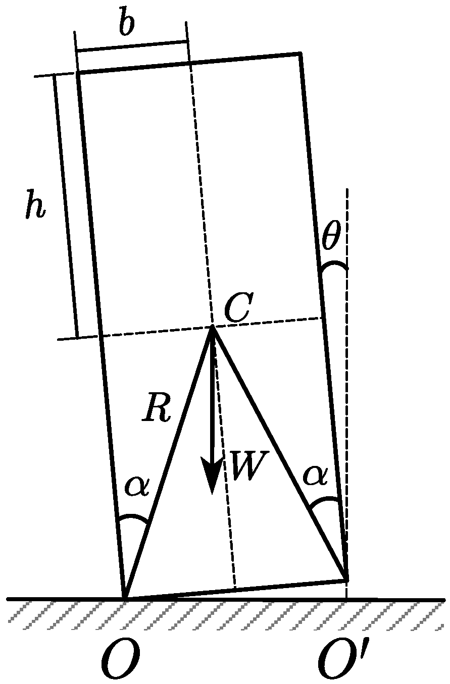
2.1. Classical Model of the Rocking Rigid Body
- The model is simplified for a 2-D geometry;
- The block and the base are rigid;
- The rigid body is a homogeneous rectangular block;
- There is no bouncing or complete lifting of the body;
- Blocks are assumed not to be sliding on the ground or relative to each other;
- Material stiffness and damping are not considered, i.e., the blocks cannot be compressed nor do they store/dissipate elastic energy;
- The collision lasts for an infinitely small time interval;
- The rigid body is not damaged during the collision.
- The conservation of angular momentum presupposes that the net external torque on the system is zero. However, during the collision, the rigid body is subjected to a net external torque from combined forces such as gravity, impact, and friction, which is not zero. Hence, the entire system, consisting of the rigid body and the ground, satisfies the conditions for the conservation of angular momentum, rather than the rigid body system itself, meaning that the angular momentum of the rigid body system does not conserve during the collision process.
- Before the collision, the center of rotation for the rigid body system is at point . At this time, the angular momentum of the system about point is not the entirety of the angular momentum possessed by the rigid body system but rather the relative angular momentum generated at point by the velocity of the system rotating about point . It is also unreasonable to equate the relative angular momentum of the rigid body system before the collision about with the entire angular momentum possessed by the rigid body after the collision.
- Although the model assumes that the angular momentum of the rigid body system about point is conserved before and after the collision and calculates the collision restitution coefficient for the rocking rigid body based on this assumption, the model implicitly uses the difference in the magnitude of the angular momentum of the rigid body about points and before the collision, denoted as , to represent the change in the magnitude of the angular momentum of the rigid body system during the collision, i.e., the reduction in angular momentum of the rigid body system during the collision. The collision described by this model is a complex process, and using to represent the reduction in angular momentum of the rigid body system does not clarify its actual significance from a mechanical standpoint.
- In previous studies, the collision restitution coefficient for rocking rigid bodies calculated by this theory has shown significant discrepancies compared to experimental values.
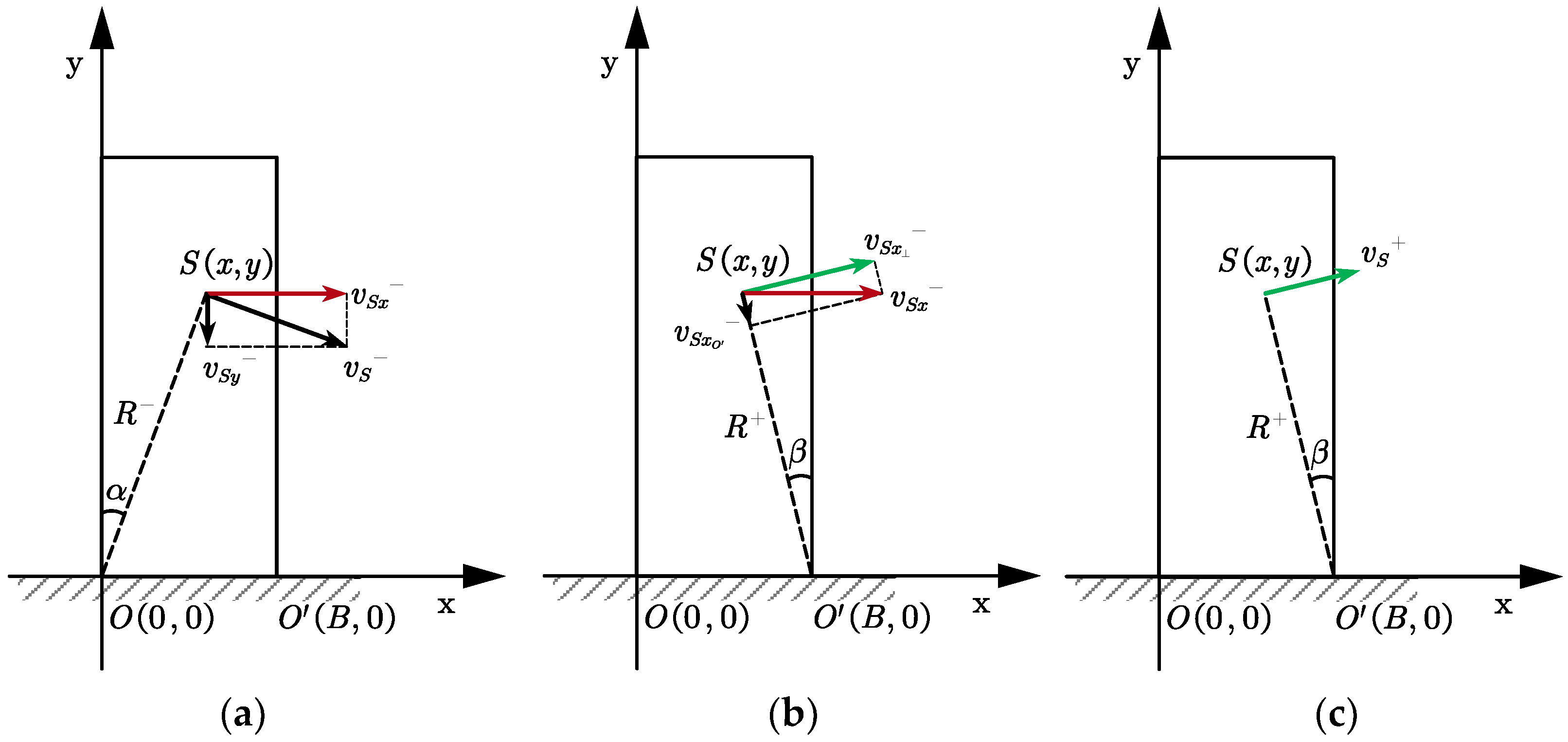
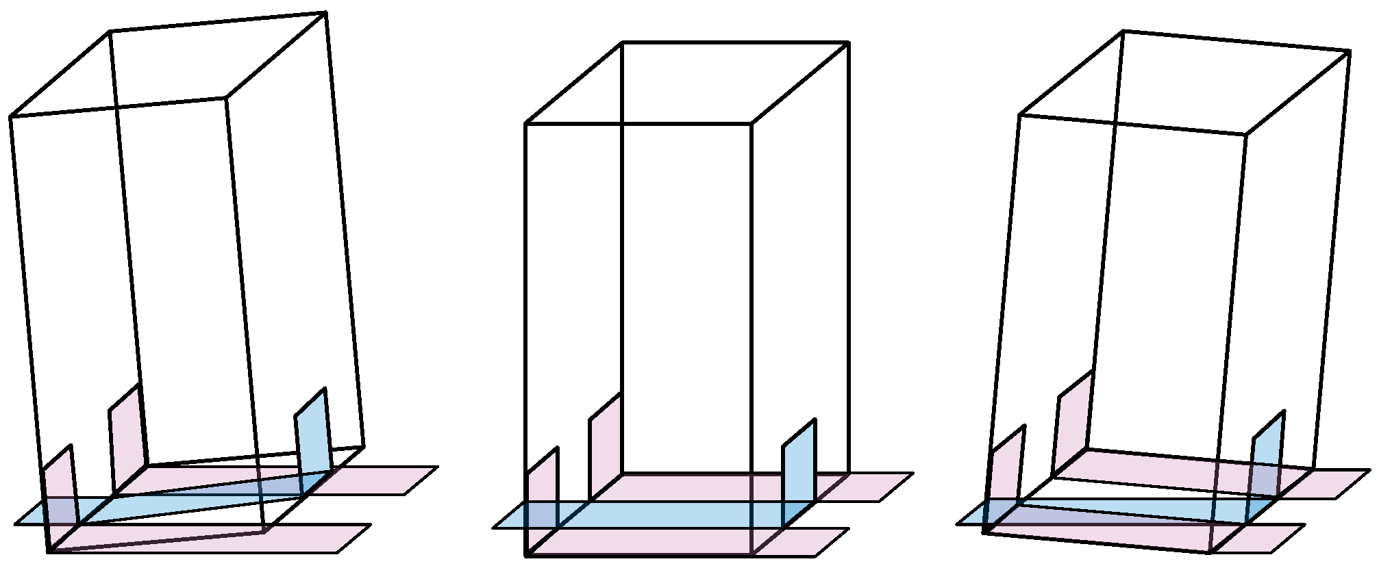
2.2. Kinetic Energy Distribution Model of the Rocking Rigid Body within the System of Mass Point
- Moment of rotation around point before collision. The kinetic energy at point of the rigid body is decomposed into kinetic energy , which is parallel to the ground, and kinetic energy , which is perpendicular to the ground. Due to the collision, the kinetic energy , which is perpendicular to the ground, is completely dissipated.
- Moment of collision. The kinetic energy , which is parallel to the ground, is further decomposed into kinetic energy along the direction and kinetic energy perpendicular to direction . The center of rotation shifts from point to point , and the kinetic energy along direction is completely dissipated under the combined action of the vertical reaction force from the ground and the horizontal frictional force.
- Moment of rotation around point after collision. The finite element analysis conducted by Kouris et al. [25] indicates that the variation of stress within the rigid block during the collision process is quite complex, and it is not appropriate to deduce the changes in the kinetic energy distribution of the rigid body within the system of mass points based on the alteration of stresses within the rigid body. Based on the assumption that the rigid body remains undamaged during the collision, the velocity of each point within the rigid body system is redistributed under the influence of the stresses. The total sum of kinetic energy at each point of the rigid body does not increase or decrease during this process; hence, the kinetic energy along the perpendicular direction is redistributed into kinetic energy rotating around .
3. Validation of the Results
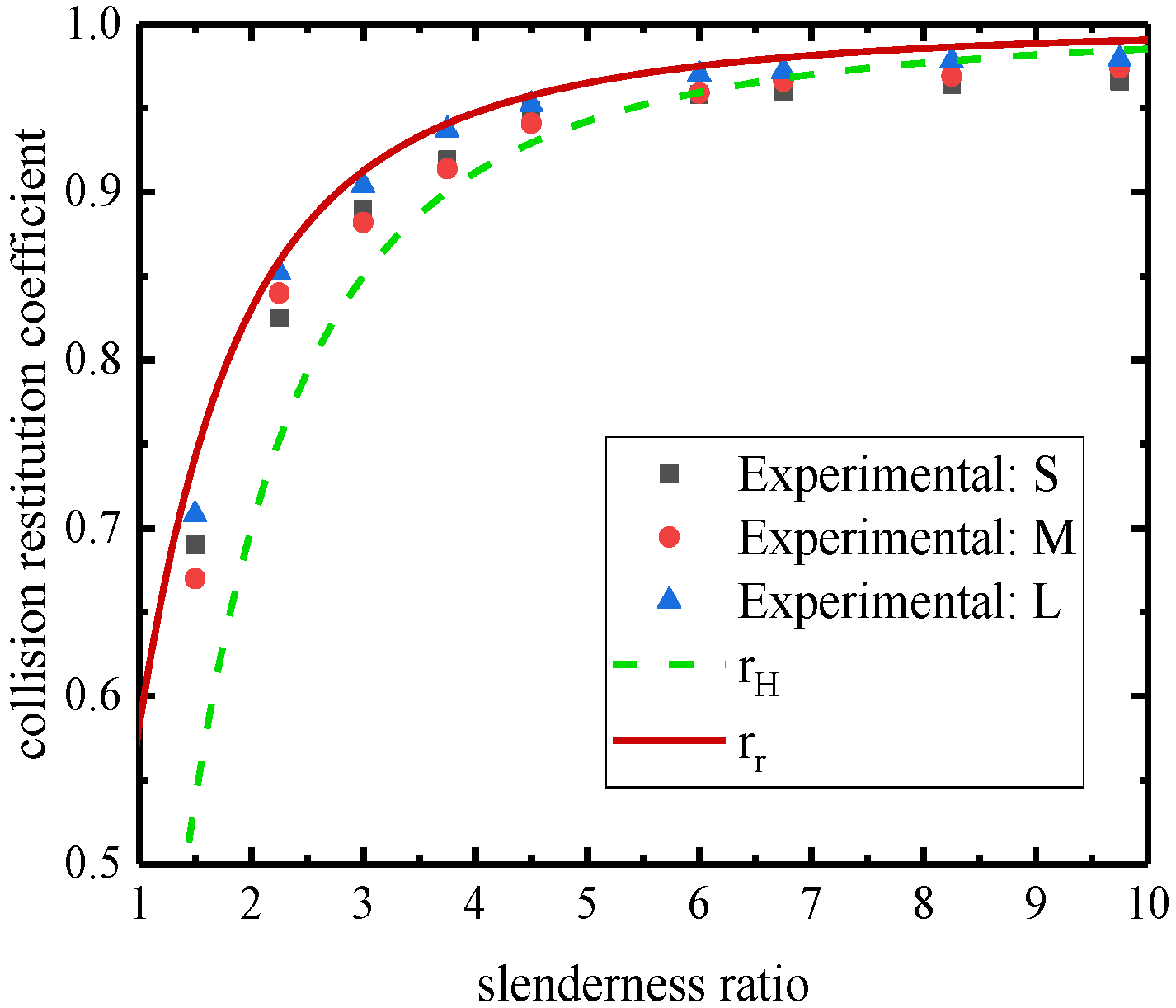
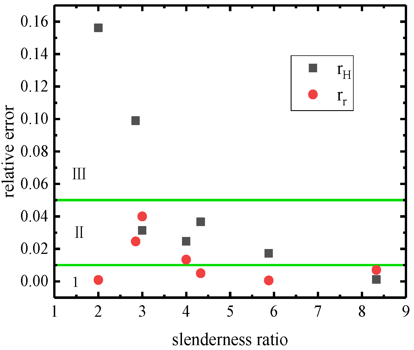
3.1. Verification of Analytical Solution under Various Slenderness Ratios
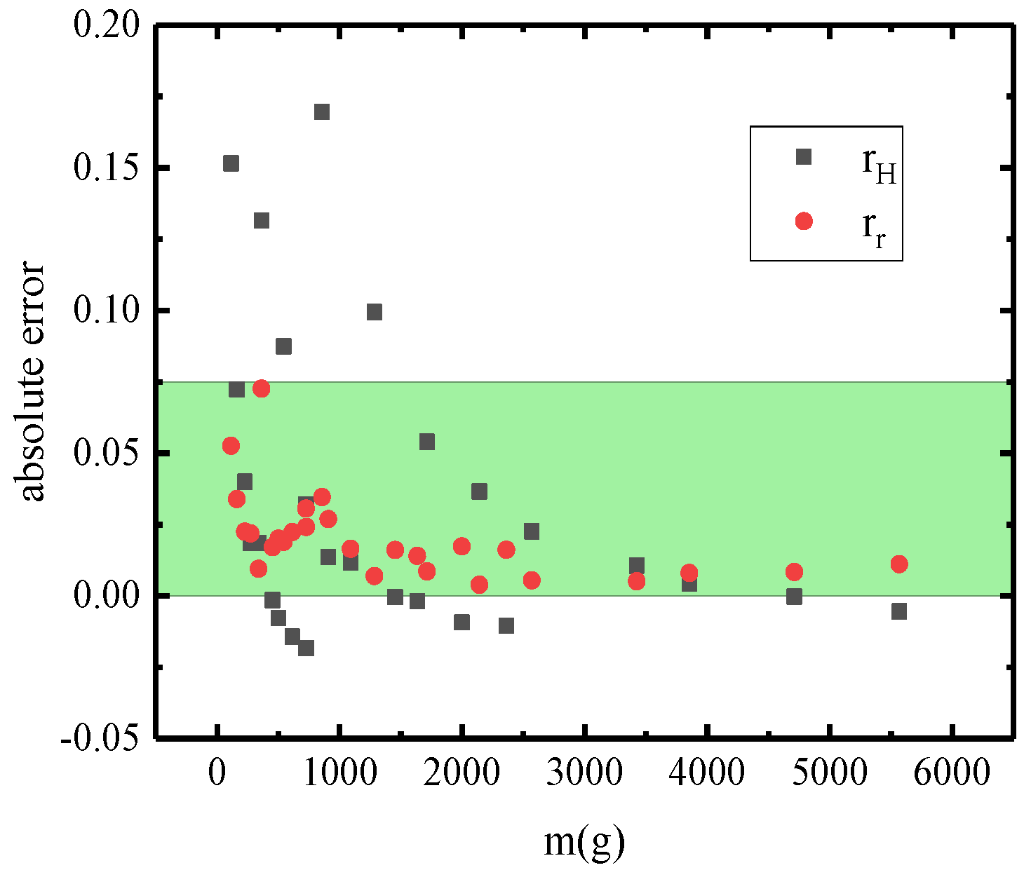
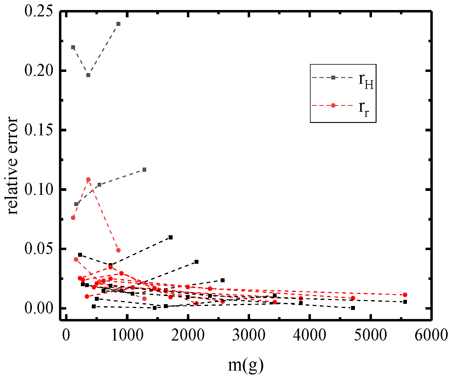
3.2. Correlation and Error Analysis
4. Conclusions
- The kinetic energy distribution model of the rocking rigid body within the system of mass points, starting from the kinetic energy and based on the energy dissipation mechanism during collisions, calculates the energy loss and conservation phases separately, which aligns more closely with reality and shows a higher degree of agreement with experimental data. Since small components initially have lower kinetic energy and are subject to more influencing factors, the advantages of this theory are more prominent in larger structures.
- The analytic solution presented in this study is derived under the ideal conditions of extremely short collision times and negligible horizontal kinetic energy loss. However, actual collisions involve a brief contact time, primarily related to the materials involved in the collision and the instantaneous velocity. Therefore, the precision of the corresponding solutions varies with different materials and masses of the rigid bodies. If the collision time could be determined and the loss of horizontal kinetic energy taken into account, the accuracy of the solutions could be further improved.
- In order to further improve the proposed model to explore the energy loss caused by non-instantaneous collision and friction in the swaying rigid body, it is necessary to analyze the contact between the rigid body and the ground during the collision process. The collision surface of the rigid body can be divided into a certain number of points. By introducing parameters such as the mass and elastic modulus of the rigid body, the force at each point in the collision process and the contact time with the ground can be calculated, and the kinetic energy lost during the collision process can be calculated more accurately.
- The rigid bodies in the kinetic energy distribution model of the rocking rigid body within the system of mass points are established as homogeneous regular rectangular blocks in a two-dimensional plane. To better align with practical engineering applications, research into the collision restitution coefficient for three-dimensional-space rocking rigid bodies is necessary. This model provides new insights for the analysis of rocking in non-homogeneous and irregularly shaped rigid bodies. Further research can be conducted on non-homogeneous or irregularly shaped rigid bodies to refine the existing model of the rocking rigid body.
- In order to expand the proposed model, the idea of finite element analysis can be incorporated into subsequent research, and the rigid body can be divided into multiple units to calculate its kinetic energy loss and conversion, so as to analyze the collision of non-homogeneous and irregular rigid bodies in three-dimensional space, making its application more practical.
Author Contributions
Funding
Data Availability Statement
Conflicts of Interest
Appendix A
- clear
- clc
- syms x y
- B=1;
- e=[ ];%Slenderness ratio
- H=e*B;
- s1=(y^4)/((y^2)+(B-x)^2);
- s11=int(s1,x,0,B);
- s12=int(s11,y,0,H);
- s2=((y^2)+(B-x)^2);
- s21=int(s2,x,0,B);
- s22=int(s21,y,0,H);
- S=s12/s22;
- S=double(S);
- r=sqrt(S)%collision restitution coefficient
References
- Jeong, M.Y.; Lee, H.; Kim, J.H.; Yang, I.Y. Chaotic behavior on rocking vibration of rigid body block structure under two―dimensional sinusoidal excitation (in the case of no sliding). KSME Int. J. 2003, 17, 1249–1260. [Google Scholar] [CrossRef]
- Jeong, M.Y.; Yang, I.Y. Characterization on the rocking vibration of rigid blocks under horizontal harmonic excitations. Int. J. Precis. Eng. Manuf. 2012, 13, 229–236. [Google Scholar] [CrossRef]
- Zheng, X.W.; Li, H.N.; Gardoni, P. Hybrid Bayesian-Copula-based risk assessment for tall buildings subject to wind loads considering various uncertainties. Reliab. Eng. Syst. Saf. 2023, 233, 109100. [Google Scholar] [CrossRef]
- Zheng, X.W.; Li, H.N.; Shi, Z.Q. Hybrid AI-Bayesian-based demand models and fragility estimates for tall buildings against multi-hazard of earthquakes and winds. Thin-Walled Struct. 2023, 187, 110749. [Google Scholar] [CrossRef]
- Housner, G.W. The behavior of inverted pendulum structures during earthquakes. Bull. Seismol. Soc. Am. 1963, 53, 403–417. [Google Scholar] [CrossRef]
- Zhao, Z.; Su, X. Literature review of researches on rigid body model of rocking structure. Eng. Mech. 2019, 36, 12–24. [Google Scholar]
- Jia, C.; Pan, J.; Li, J.; Jia, C.; Pan, J.; Li, J.; Ma, L. Seismic analysis of eccentric single-rigid-body considering the influence of colliding-to-wall. J. Vib. Shock. 2022, 41, 116–123. [Google Scholar]
- Beck, J.L.; Skinner, R.I. The seismic response of a reinforced concrete bridge pier designed to step. Earthq. Eng. Struct. Dynamics 1973, 2, 343–358. [Google Scholar] [CrossRef]
- Du, X.-L.; Zhou, Y.-L.; Han, Q.; Wang, Z. State-of-the-art on rocking piers. Earthq. Eng. Eng. Dyn. 2018, 38, 1–11. Available online: https://dzgc.paperonce.org/#/digest?ArticleID=2426 (accessed on 27 December 2023).
- Hukelbridge, A.A.; Clough, R.W. Preliminary Experimental Study of Seismic Uplift of a Steel Frame; Report No. UCB/EERC-77/22; University of California: Berkely, CA, USA, 1977. [Google Scholar]
- Hukelbridge, A.A. Earthquake Simulation Tests of a Nine Story Steel Frame with Columns Allowed to Uplift; Report No. UCB/EERC-77/23; University of California: Berkely, CA, USA, 1977. [Google Scholar]
- Zhou, Y.; Lü, X. State-of-the-art on rocking and self-centering structures. J. Build. Struct. 2011, 32, 1–10. [Google Scholar]
- Yim, C.; Chopra, A.K.; Joseph, P. Rocking response of rigid blocks to earthquake. Earthq. Eng. Struct. Dyn. 1980, 8, 565–587. [Google Scholar] [CrossRef]
- Aslam, M.; Scalise, D.T.; Godden, W.G. Earthquake rocking response of rigid bodies. J. Struct. Div. 1980, 106, 377–392. [Google Scholar] [CrossRef]
- Cormack, L.G. The design and construction of the major bridges on the mangaweka rail deviation. Trans. Inst. Prof. Eng. New Zealand 1988, 15, 16–23. [Google Scholar]
- Apostolou, M.; Gazetas, G.; Garini, E. Seismic response of slender rigid structures with foundation uplifting. Soil Dyn. Earthq. Eng. 2007, 27, 642–654. [Google Scholar] [CrossRef]
- Marriott, D.; Pampanin, S.; Palermo, A. Quasi-static and pseudo-dynamic testing of unbonded post-tensioned rocking bridge piers with external replaceable dissipaters. Earthq. Eng. Struct. Dyn. 2009, 38, 331–354. [Google Scholar] [CrossRef]
- Guo, T.; Cao, Z.; Xu, Z.; Lu, S. Cyclic load tests on self-centering concrete pier with external dissipators and enhanced durability [J]. J. Struct. Eng. 2015, 142, 04015088. [Google Scholar] [CrossRef]
- Han, Q.; Jia, Z.L.; Xu, K.; Zhou, Y.; Du, X. Hysteretic behavior investigation of self-centering double-column rocking piers for seismic resilience. Eng. Struct. 2019, 188, 218–232. [Google Scholar] [CrossRef]
- Han, Q.; Jia, Z.; He, W.; Xiao, Y.; Jia, J.; Du, X. Seismic design method and its engineering application of self-centering double-column rocking bridge. China J. Highw. Transp. 2017, 30, 169–177. [Google Scholar]
- Mashal, M.; Palermo, A. Low-damage seismic design for accelerated bridge construction. J. Bridge Eng. 2019, 24, 04019066. [Google Scholar] [CrossRef]
- Zhou, Y.; Zhang, J.; Han, Q.; Zhou, Y.; Zhang, J.; Han, Q.; Cheng, S.; He, H. Effect of viscous dampers on seismic response of rocking double-column bents under near-field ground motions with strong pulses. China Civ. Eng. J. 2020, 53, 288–293. [Google Scholar]
- Kalliontzis, D.; Schultz, A.E.; Sritharan, S. Generalized dynamic analysis of structural single rocking walls (SRWs). Earthq. Eng. Struct. Dyn. 2020, 49, 633–656. [Google Scholar] [CrossRef]
- Avgenakis, E.; Psycharis, I. An integrated macroelement formulation for the dynamic response of inelastic deformable rocking bodies. Earthq. Eng. Struct. Dyn. 2020, 49, 1072–1094. [Google Scholar] [CrossRef]
- Kouris, E.-G.S.; Kouris, L.-A.S.; Konstantinidis, A.A.; Kourkoulis, S.K.; Karayannis, C.G.; Aifantis, E.C. Stochastic dynamic analysis of cultural heritage towers up to collapse. Buildings 2021, 11, 296. [Google Scholar] [CrossRef]
- Kazantzi, A.K.; Lachanas, C.G.; Vamvatsikos, D. Seismic response distribution expressions for on-ground rigid rocking blocks under ordinary ground motions. Earthq. Eng. Struct. Dyn. 2021, 50, 3311–3331. [Google Scholar] [CrossRef]
- Várkonyi, P.L.; Kocsis, M.; Ther, T. Rigid impacts of three-dimensional rocking structures. Nonlinear Dyn. 2022, 107, 1839–1858. [Google Scholar] [CrossRef]
- Thomaidis, I.M.; Camara, A.; Kappos, A.J. Dynamics and seismic performance of asymmetric rocking bridges. J. Eng. Mech. 2022, 148, 04022003. [Google Scholar] [CrossRef]
- Schau, H.; Johannes, M. Rocking and sliding of unanchored bodies subjected to seismic load according to conventional and nuclear rules. In Proceedings of the 4th International Conference on Computational Methods in Structural Dynamics and Earthquake Engineering, Kos Island, Greece, 12–14 June 2013. [Google Scholar]
- Kalliontzis, D.; Sritharan, S.; Schultz, A. Improved coefficient of restitution estimation for free rocking members. J. Struct. Eng. 2016, 142, 06016002. [Google Scholar] [CrossRef]
- Čeh, N.; Jelenić, G.; Bićanić, N. Analysis of restitution in rocking of single rigid blocks. Acta Mech. 2018, 229, 4623–4642. [Google Scholar] [CrossRef]
- Anagnostopoulos, S.; Norman, J.; Mylonakis, G. Fractal-like overturning maps for stacked rocking blocks with numerical and experimental validation. Soil Dyn. Earthq. Eng. 2019, 125, 105659. [Google Scholar] [CrossRef]


| Slenderness Ratio (h/b) | Relative Error | Block and Base (Materials at Contact Interface) | ||
|---|---|---|---|---|
| 2 | 0.787401 | 0.7 | 0.110999 | wood/steel |
| 2 | 0.87178 | 0.7 | 0.197045 | concrete/aluminum |
| 2.85 | 0.927362 | 0.836 | 0.097806 | granite/granite |
| 3 | 0.877496 | 0.85 | 0.033012 | wood/steel |
| 4 | 0.938083 | 0.912 | 0.028825 | wood/steel |
| 4 | 0.927362 | 0.912 | 0.017597 | concrete/steel |
| 4 | 0.938083 | 0.912 | 0.028825 | granite/granite |
| 4 | 0.948683 | 0.912 | 0.039676 | wood/aluminum |
| 4 | 0.921954 | 0.912 | 0.011835 | steel/steel |
| 4.33 | 0.959166 | 0.924 | 0.016439 | steel/wood |
| 5.88 | 0.974679 | 0.958 | 0.015916 | granite/granite |
| 8.33 | 0.979796 | 0.979 | 0 | granite/granite |
| Slenderness Ratio (h/b) | |||
|---|---|---|---|
| 2 | 0.8295905 | 0.7 | 0.83030915 |
| 2.85 | 0.927362 | 0.83666 | 0.90454519 |
| 3 | 0.877496 | 0.848528 | 0.91256288 |
| 4 | 0.934833 | 0.911043 | 0.94736684 |
| 4.33 | 0.959166 | 0.943398 | 0.95441345 |
| 5.88 | 0.974679 | 0.959166 | 0.97412902 |
| 8.33 | 0.979796 | 0.979796 | 0.98664748 |
| Block | m (g) | Slenderness Ratio (h/b) | re | rH | rr |
|---|---|---|---|---|---|
| S1 | 113.3 | 1.5 | 0.69 | 0.538 | 0.743 |
| S2 | 161.2 | 2.25 | 0.825 | 0.753 | 0.859 |
| S3 | 226.6 | 3 | 0.89 | 0.850 | 0.913 |
| S4 | 274.5 | 3.75 | 0.919 | 0.900 | 0.941 |
| S5 | 339.6 | 4.5 | 0.948 | 0.929 | 0.958 |
| S6 | 453.2 | 6 | 0.958 | 0.959 | 0.975 |
| S7 | 500.8 | 6.75 | 0.96 | 0.968 | 0.980 |
| S8 | 614.1 | 8.25 | 0.964 | 0.978 | 0.986 |
| S9 | 727.4 | 9.75 | 0.966 | 0.984 | 0.990 |
| M1 | 363.6 | 1.5 | 0.67 | 0.538 | 0.743 |
| M2 | 544.4 | 2.25 | 0.84 | 0.753 | 0.859 |
| M3 | 727.2 | 3 | 0.882 | 0.850 | 0.913 |
| M4 | 907.7 | 3.75 | 0.914 | 0.900 | 0.941 |
| M5 | 1089.6 | 4.5 | 0.941 | 0.929 | 0.958 |
| M6 | 1453.2 | 6 | 0.959 | 0.959 | 0.975 |
| M7 | 1634 | 6.75 | 0.966 | 0.968 | 0.980 |
| M8 | 1997.6 | 8.25 | 0.969 | 0.978 | 0.986 |
| M9 | 2361.2 | 9.75 | 0.974 | 0.984 | 0.990 |
| L1 | 856.6 | 1.5 | 0.708 | 0.538 | 0.743 |
| L2 | 1284.3 | 2.25 | 0.852 | 0.753 | 0.859 |
| L3 | 1713.2 | 3 | 0.904 | 0.850 | 0.913 |
| L4 | 2140.9 | 3.75 | 0.937 | 0.900 | 0.941 |
| L5 | 2569.2 | 4.5 | 0.952 | 0.929 | 0.958 |
| L6 | 3425.8 | 6 | 0.97 | 0.959 | 0.975 |
| L7 | 3853.5 | 6.75 | 0.972 | 0.968 | 0.980 |
| L8 | 4710.1 | 8.25 | 0.978 | 0.978 | 0.986 |
| L9 | 5566.7 | 9.75 | 0.979 | 0.984 | 0.990 |
Disclaimer/Publisher’s Note: The statements, opinions and data contained in all publications are solely those of the individual author(s) and contributor(s) and not of MDPI and/or the editor(s). MDPI and/or the editor(s) disclaim responsibility for any injury to people or property resulting from any ideas, methods, instructions or products referred to in the content. |
© 2024 by the authors. Licensee MDPI, Basel, Switzerland. This article is an open access article distributed under the terms and conditions of the Creative Commons Attribution (CC BY) license (https://creativecommons.org/licenses/by/4.0/).
Share and Cite
Mao, Q.; Deng, T.; Shen, B.; Wang, Y. Research on Collision Restitution Coefficient Based on the Kinetic Energy Distribution Model of the Rocking Rigid Body within the System of Mass Points. Buildings 2024, 14, 2119. https://doi.org/10.3390/buildings14072119
Mao Q, Deng T, Shen B, Wang Y. Research on Collision Restitution Coefficient Based on the Kinetic Energy Distribution Model of the Rocking Rigid Body within the System of Mass Points. Buildings. 2024; 14(7):2119. https://doi.org/10.3390/buildings14072119
Chicago/Turabian StyleMao, Qiuyu, Tongfa Deng, Botan Shen, and Yuexin Wang. 2024. "Research on Collision Restitution Coefficient Based on the Kinetic Energy Distribution Model of the Rocking Rigid Body within the System of Mass Points" Buildings 14, no. 7: 2119. https://doi.org/10.3390/buildings14072119
APA StyleMao, Q., Deng, T., Shen, B., & Wang, Y. (2024). Research on Collision Restitution Coefficient Based on the Kinetic Energy Distribution Model of the Rocking Rigid Body within the System of Mass Points. Buildings, 14(7), 2119. https://doi.org/10.3390/buildings14072119