Abstract
The 2020 Zagreb earthquake caused extensive damage to historically significant buildings, including the Cathedral of the Assumption of Mary, a key monument of Croatian cultural heritage. The earthquake rendered the cathedral unsafe due to significant damage to its towers and numerous cracks in its vaults and walls. Urgent measures were necessary to ensure safety and facilitate planned reconstruction and strengthening efforts. A specialised scaffolding design was developed to support inaccessible and unstable areas, involving over 1000 tonnes of steel. This paper details the structural concepts and specific scaffolding design implemented for the urgent restoration and seismic retrofitting of Zagreb Cathedral, ensuring it meets high earthquake resistance requirements.
1. Introduction
1.1. A Brief History of the Zagreb Cathedral
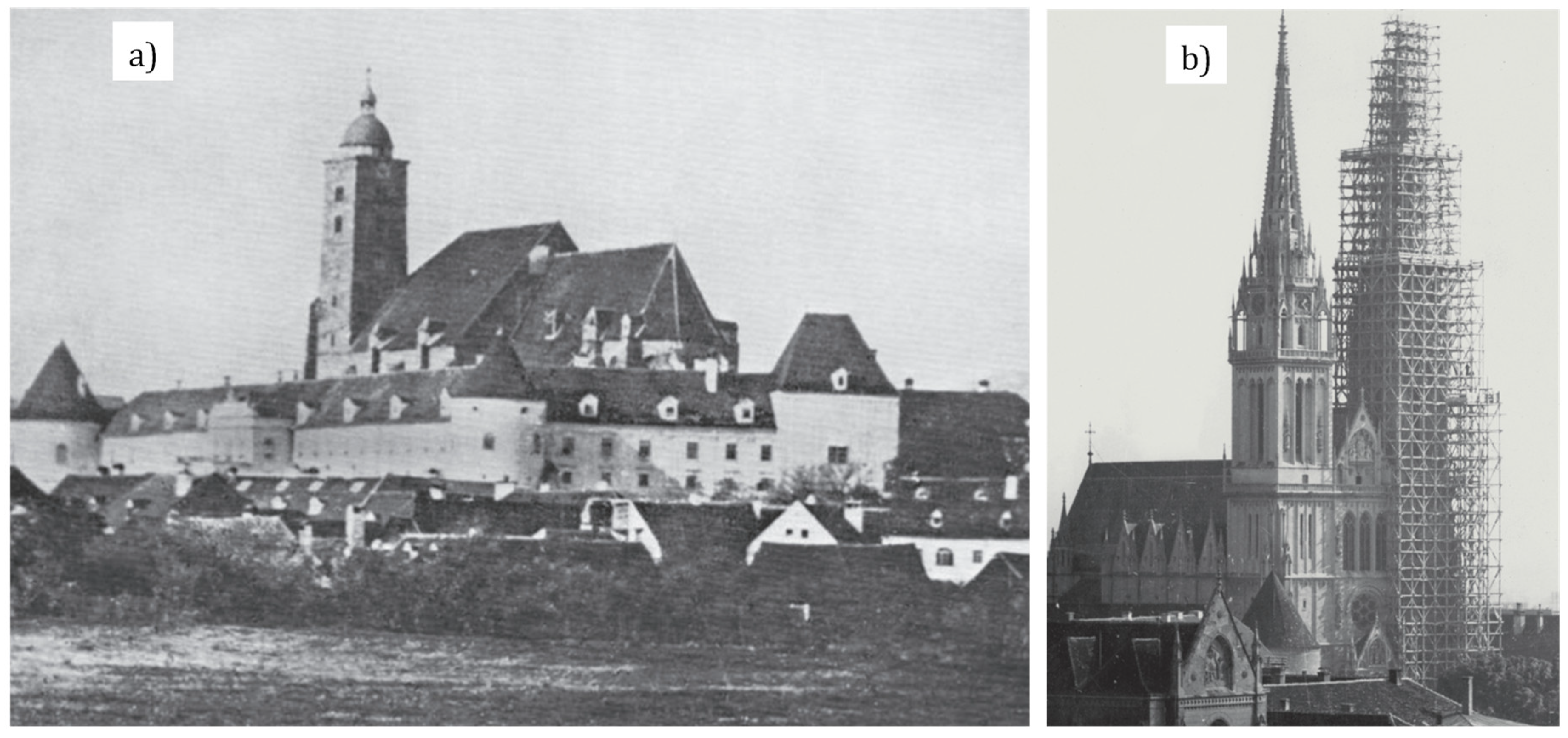
According to the Felicijan Charter of 1134, the founder of Zagreb Cathedral was King Ladislav. After his death, construction work began on the new cathedral, which lasted more than 100 years, and in 1217, it was consecrated to the Virgin Mary. During the Tartar invasion at the beginning of the 13th century, the cathedral was almost completely destroyed, leaving the sacristy and remains that indicate the transitional Romanesque style in which it was built. After the Tartar invasion, construction work began on the new cathedral in the Gothic style, when the central and two side apses as well as the sacristy were built. In the second half of the 15th century, during the time of Bishop Osvald Thuz, the entire building was roofed over and construction of the bell tower on the south side of the façade began; see Figure 1a [1]. After two major fires in the 17th century, the cathedral was upgraded several times during subsequent renovations, and the interior was redesigned.
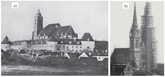
Figure 1.
Zagreb Cathedral: (a) before the earthquake of 1880 [1], (b) restoration of the southern bell tower, 1938–1940 [2].
The earthquake of magnitude 6.3 that shook Zagreb on 9 November 1880 caused severe damage to the magnificent cathedral. The vaults collapsed, the floor and the altar were shattered, and the bell tower was damaged. The above-mentioned damage necessitated a thorough renovation of the cathedral, which was carried out by Hermann Bollé according to the plans of master builder Friedrich Schmidt in the neo-Gothic style. During this renovation, the cathedral was given a new façade with 105-metre-high towers. The renovation was completed in 1902 and the cathedral was given its current, recognisable appearance.
The progressive deterioration of the limestone used in the renovation after the earthquake of 1880 led to new damage and thus to a new renovation, which began in 1938 and in which the entire south tower was renovated; see Figure 1b [2]. The last renovation of the cathedral began in December 1990 and lasted until the last earthquake measuring 5.5 on the Richter scale shook Zagreb on 22 March 2020. At the time of the earthquake, the south tower had a tubular scaffolding that rested on the first gallery of the cathedral at a height of 36.8 m and reached almost the height of the third gallery of the south tower at a height of 66.4 m. This scaffolding is referred to as the “old scaffolding” later in this paper. There was also an elevator manufactured by “Alimak”, which provided vertical communication from the ground floor to the access path at a height of around 45 m.
1.2. The Condition of the Cathedral after the 2020 Earthquakes
After the earthquake in Zagreb in 2020, the most severely damaged buildings were old, unreinforced brick buildings of poor quality, without horizontal and especially vertical cerclages and with dilapidated wooden ceilings and roofs. In the sacred buildings, the decorative cantilever elements, vaults and bell towers were severely affected, mostly due to poor anchoring, lack of tension and weak connections between the stone elements (with short, lead-filled iron pins) [3].
One of the major damages to the cathedral after the earthquake in March 2020 was the collapse of the stone spire of the south tower. The fracture occurred at a height of around 95 m and the 10.3-metre-high part of the tower, on which there was a gilded cross with a 3.2-metre-high lightning rod, collapsed. As some of the stone elements fell onto the old scaffolding used for the renovation of the south tower, part of the tower’s recently completed third gallery at a height of 66.4 m was damaged. Some of the stone elements also fell onto the roof of the cathedral, damaging it further and breaking through it. During a controlled demolition on 17 April 2020, the 13-metre-high spire of the north tower was successfully removed as it was severely damaged. Following the removal of the spire, scaffolding was urgently erected inside the apse and choir (see Section 3.2. for more information) to support the vaults in the apse and choir, where the greatest damage to the vaults was initially found. The scaffolding also enabled a detailed assessment of the condition of the interior of the apse and choir, as well as a stable working environment for restorers and engineers. In the same year, on 29 December, city of Petrinja was shaken by an earthquake with a magnitude of 6.2 on the Richter scale. Although the distance to the epicentre of the Petrinja earthquake was about 60 km south-east of Zagreb, further damage occurred throughout the cathedral, particularly to the upper parts of the towers and the walls of the central apse. Distant earthquakes usually affect the vibration modes of a structure which have longer periods. In the case of the cathedral, these were the towers and the central apse, as their stiffness had decreased considerably due to the effects of the series of earthquakes in Zagreb.
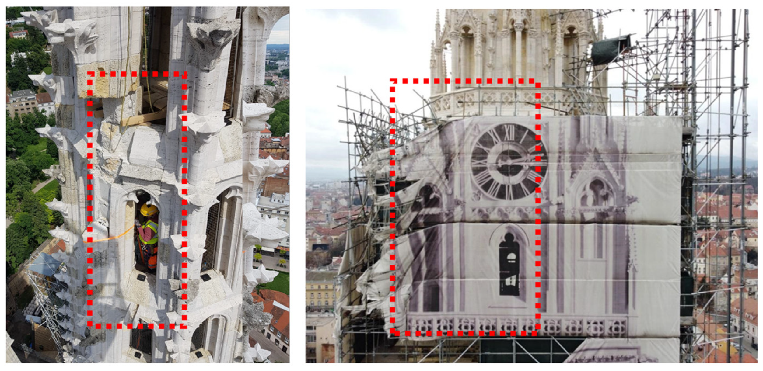
The old scaffolding on the south tower was also damaged; see Figure 2. The broken stone elements of the towers fell onto the scaffolding and damaged part of its structure. Due to the jeopardised stability and deterioration of the existing scaffolding, as well as the complexity of the future retrofitting work, it had to be removed and replaced with new scaffolding. A mobile crane with a maximum capacity of 120 tonnes and a maximum reach of 120 m was used to dismantle the old scaffolding. The old scaffolding was dismantled by removing it piece by piece and transporting the dismantled parts to the ground using a mobile crane with a construction basket. The removal was completed at the end of 2022 before the new scaffolding was erected in 2023.
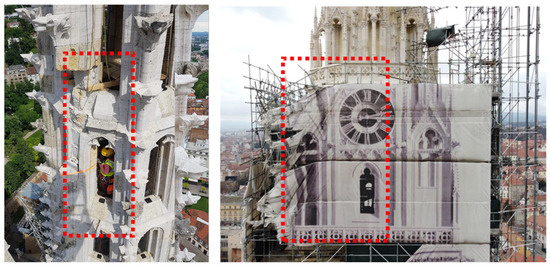
Figure 2.
Damage to the south tower and the old tubular scaffolding after the 2020 earthquake.
2. Urgent Seismic Retrofitting Design Concept
The restoration requires the cathedral to have significant earthquake resistance (at least retrofit level three [4]). This is a challenging design task, especially considering the monumental size of the cathedral, the historic, traditional construction methods used and its extraordinary cultural and sacred significance. The main concept is to apply reversible retrofitting with steel that fits easily into the irregular geometry of the cathedral which can be monitored and maintained in the future [5].
Due to the damage to the towers and numerous cracks in the vaults and walls, the cathedral was categorised as unsafe for use after the earthquake. The original aim was to stabilise the cathedral with urgent measures so that the subsequently planned reconstruction work could be carried out. These activities were to be led by the Faculty of Civil Engineering at the University of Zagreb in cooperation with several design offices (Toding, Studio Arhing, Foretić and Sons) and numerous experts, including monument conservators. The design and implementation of the urgent stabilisation and reinforcement work was co-funded by the European Union Solidarity Fund. The photogrammetric survey of the cathedral and the extensive investigation work (dynamic properties of the structure, properties of the materials used, condition assessment of the structural components) provided essential data for the urgent restoration projects of Zagreb Cathedral. Figure 3 shows the point cloud model and the preliminary numerical models created by the author of the retrofit concept, Prof Dr Damir Lazarević, together with a close team of collaborators from the Faculty of Civil Engineering at the University of Zagreb. The basis for the creation of the numerical model was a point cloud model, on the basis of which first a spatial model and then a numerical model of the deformable blocks was created [6]. In developing the urgent measures, these numerical models were calibrated using small-scale models [7,8,9] based on the latest scientific, especially experimental, research on the behaviour of stone masonry worldwide. This approach highlighted the highly complex behaviour of the cathedral and underlined the need for a complete seismic retrofit of the structure.
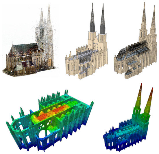
Figure 3.
Point cloud model and preliminary numerical models of the Zagreb Cathedral [6].
There are several examples of seismic retrofitting of similar historic buildings, but these mainly focus on specific structural parts and possible failures [10,11,12]. Due to its location, its particular historical heritage and the seismic vulnerability of the region, Zagreb Cathedral, which has suffered numerous damages in recent earthquakes, is a unique example of a damaged sacral building in the world. As the description of the complex behaviour of the Zagreb Cathedral requires a lot of space and would go beyond the scope of this work, the basic data for the creation of a numerical model and the definition of the seismic load are listed below.
The calculations were performed on a materially and geometrically nonlinear spatial model using the 3DEC programme [13], which is based on the method of deformable discrete elements (blocks), with models of block failure and failure of the connections between blocks. For deformability, the blocks are subdivided by a grid of tetrahedral regions (elements or zones) based on a mixed formulation using the finite difference method. There are practically no restrictions on how the blocks and the connection between blocks can fail. Any compatibility or connection between the blocks can be broken (by sliding, separating, rotating, elements falling off, etc.). Before calculating the main model, the results of several important experiments up to the complete failure of the specimen were reproduced: the entire hysteresis loop of any load-bearing element (e.g., a wall or a crossbeam) subjected to a regularly increasing cyclic load.
The seismic load was defined by time history records with impulses (recorded during the 2020 earthquakes series). The recordings were adapted to the location of the building, taking into account the characteristics of all major sources influencing the seismic loading of the site (distribution and mechanisms of fault opening, foundation conditions, etc.). Close cooperation with geologists, geophysicists, seismologists and geotechnical engineers was extremely important [14,15,16,17,18,19]. The recording spectra statistically match the elastic response spectra of the site for 5% damping. The matching criteria were defined in the EN standards and Croatian national annex [20,21,22]. These are type 1 and 2 spectra with a return period of 475 years multiplied by 0.9, since the planned retrofitting level is three (0.75 of the “full” spectrum) and the coefficient of the building is 1.2, resulting in 0.75 × 1.2 = 0.9. The peak ground acceleration on the site is 0.26 g [17].
In order to carry out the urgent restoration work and complete the structural retrofitting of the cathedral, it was necessary to design scaffolding that would allow work to be carried out in inaccessible areas and support unstable elements of architectural and cultural heritage that were damaged during the earthquake. The designed scaffolding also serves to protect and secure the stone elements of the towers and the figures around the towers, which were destabilised by the earthquake shaking, from a possible uncontrolled collapse, as stated in the Preliminary Report on the Assessment of the Existing Structural Condition of the cathedral [23]. The stabilisation of these elements was crucial in preventing the endangerment of human lives and permanent damage to cultural heritage. In addition, the load-bearing scaffolding and platforms provide protection from potentially uncontrolled falling objects, especially decorative heritage elements and small stone fragments.
To fulfil this function, scaffolding was designed inside the cathedral, around its perimeter and for the towers. The internal scaffolding supports and secures the vault structures from the inside, while the external scaffolding supports and facilitates the restoration work from the outside. The (western) tower scaffolding is intended for the dismantling and reconstruction of the upper floors of the stone towers and for the installation of new structures for their seismic strengthening. Although a number of experts were involved in the design of the scaffolding, the core team consisted of Prof Dr Davor Skejić (lead structural designer of the scaffolding) and close collaborators, assistants Ivan Čudina and Anđelo Valčić. The contribution of the reviewer, Mr Ivan Palijan, MSc, was also of great importance for the definition of the structural concept.
3. Scaffolding Structures
3.1. General
Although the tubular scaffolding is geometrically more adaptable, due to the required reliability and uncertain design parameters, it was decided that a modular scaffolding based on typical solutions of certified systems was used. The main advantage of modular scaffolding is its standardisation, which enables faster and safer assembly/disassembly compared to tubular scaffolding. Table 1 shows a comparison of the main parameters between tubular scaffolding and modular scaffolding, including assembly time, cost, safety, storage, etc. Table 1 shows that modular scaffolding offers significantly higher performance efficiency and safety on site despite its lower geometric adaptability.

Table 1.
Comparison of tubular and modular scaffolding.
However, the predefined modules of the scaffolding led to limitations in optimally reproducing the branched geometry of the cathedral. To address this, a detailed point cloud model of the cathedral was created, enabling precise mapping and a customised scaffolding design. The absence of detailed plans of the cathedral required significant time to create accurate models using photogrammetric surveys. This approach facilitated the careful design of all scaffolding both outside and inside the cathedral. Additionally, the high risk of further earthquakes required the scaffolding to ensure both worker safety and the structural integrity of the cathedral’s structure. Consequently, an additional function was added to the scaffolding, which was to support and brace the tower against potential further earthquakes. For instance, the south tower scaffolding was designed to handle potential stone collapses during aftershocks, focusing on stabilising damaged areas and preventing further deterioration.
The design of the scaffolding structures was carried out in accordance with Croatian regulations and standards with the relevant national annexes and local load conditions. The design of the entire steel structure was carried out using the SCIA Engineer v.20.1 [24] software package and with the help of tables and expressions from the relevant technical approvals. All the design rules for calculating the internal forces according to the second-order theory were taken into account. The design was carried out in accordance with the limit states defined in the valid technical regulations for load-bearing structures.
A group of structural Eurocodes (EN 1991, EN 1993, EN 1998 and EN 1999) and standards for the scaffolding design from the groups EN 12811 and EN 12812 were used for the design. According to EN 12811, the partial factors for the resistance of cross-sections, γM0, and for the resistance of members, γM1, were assumed to be 1.1. A significant difference between the Eurocode for the design of steel structures and the standards for the scaffolding design is reflected in the approaches for the verification of the ultimate limit state. The reliability verification according to the standard for the scaffolding design [25] is carried out at the cross-sectional level, taking into account all geometric imperfections (at system-level and member-level), but without checking the stability. In contrast, the standard for the design of steel structures (EN 1993) takes a more comprehensive approach to the verification of reliability and, in addition to the verification at the cross-sectional level, also includes the verification of the stability of members and systems. Both approaches were used for the design of the internal, external and tower (west) scaffolding.
In addition, EN 12811 defines the mandatory use of a nonlinear analysis for modular scaffolding. This means that the longitudinal stiffnesses at the ends of the members of the vertical and horizontal diagonals as well as at the ends of the horizontal members must be defined in accordance with the manufacturer’s technical approval [26]. In addition to the longitudinal stiffnesses, the rotational stiffnesses at the ends of the members were also assumed in the design model, which consider the real behaviour of the joints at the location of the rosette couplers in accordance with [26]. The rotational stiffnesses were considered using a nonlinear function of M-ϕ (moment–rotation) behaviour, as specified in [26]. Each of these couplers has its specific nonlinear functions and maximal forces, which are stored in the SCIA Engineer database [24] and which are automatically assigned when the desired coupler type is chosen.
The load analysis was carried out in a similar way for all scaffolding structures. Minor differences in the applied loads resulted from the different locations of the scaffoldings and the different types of use. In addition to the self-weight of the scaffolding and the dead load of the aluminium (weighing 13 kg/m2) or steel (weighing 27 kg/m2) platform units, a service load class LC4 in accordance with EN 12811-1 [25] was assumed for all scaffolding structures. Accordingly, each working area is loaded with 3.0 kN/m2, while the rest of the working area is loaded with 0.75 kN/m2. A load of 1.5 kN/m2 is assumed for the walkways. This heavy-duty class was chosen due to the demanding restoration work. In addition to the load from the workers and tools, the working areas of the tower scaffolding must also be able to withstand the weight of the stone elements to be removed. The external scaffolding must support the prestressing work on the buttresses, while the internal scaffolding must protect the interior of the cathedral in case the masonry vaults collapse onto the working areas.
The basic wind velocity was assumed to be 20 m/s for the external and tower scaffoldings in accordance with EN 1991-1-4 [27]. For scaffolding erected on the towers, terrain category I [27] was assumed as these scaffoldings are particularly exposed to the wind due to their height. The coefficients for buildings (Section 7.2.2 of EN 1991-1-4 [27]) were used to determine the wind pressure coefficients for the tower scaffolding with sheeting, while the coefficients for truss structures (Section 7.11 of the same standard [27]) were used for the uncovered part. The mounting of sheeting is permitted up to the 12th level (the highest anchored level) according to the main structural design project [28]. For the external scaffolding on the walls of the cathedral, terrain category IV [27] and the wind pressure coefficient for circular cylinders according to [27] were assumed.
The snow action was assumed in accordance with EN 1991-1-3 [29]. In the case of tower scaffoldings, the accumulation of ice on the tubular members without sheeting was also taken into account due to the great height of the structures. In accordance with prEN 1991-1-9:202x [30], a 10 mm thick layer of ice (ICG category G1) was assumed.
The seismic analysis was performed for ground type A, peak ground acceleration ag = 0.25 g, importance factor II and for both types of response spectra (type 1 and type 2).
For load combinations, all loads on temporary objects are magnified by a factor of 1.5 in accordance with EN 12811. According to EN 12811-1 [25], it is assumed that no work is carried out on scaffolding at maximum wind velocity. The standard therefore specifies a maximum wind load value for the basic velocity pressure of 0.2 kN/m2 when work is carried out on scaffolding. This is referred to as the working wind load situation and is combined with the service load of the scaffolding. The maximum wind load determined in accordance with EN 1991-1-4 [27] is not combined with the service load of the scaffolding.
The load-bearing members of the ‘LAYHER Allround’ modular scaffolding system are round tubes with a diameter of 48.3 mm in various wall thicknesses and steel grades, depending on the function. The dimensions of the columns are 48.3 × 2.9, and those of the horizontal members are 48.3 × 2.7, all made of steel S 460 MH. The vertical diagonals measure 48.3 × 2.3 and are made of S 235 JR steel. The modular scaffolding members are connected with a system of rosette couplers and wedges. The rosette couplers are fitted every 500 mm along the height of the columns, and a maximum of eight members can be connected to them. It should be noted that due to specific technical requirements, tubular scaffolding members with CHS 48.3 × 4 made of steel grade S 235 were also used in addition to the typical modular scaffolding members, mostly as vertical or horizontal bracings. Rigid or swivelling couplers were used to connect the classic scaffolding members with the modular scaffolding members. Aluminium or steel platform units form working areas. At the outer edges of working areas is a fence consisting of handrails and mid rails, as well as a toe board consisting of a vertically arranged element.
To obtain an idea of the size of the scaffolding, it should be noted that 23,080 structural members were used for the internal scaffolding, 12,415 for the external and 46,966 for the two tower scaffoldings.
3.2. Internal Scaffolding
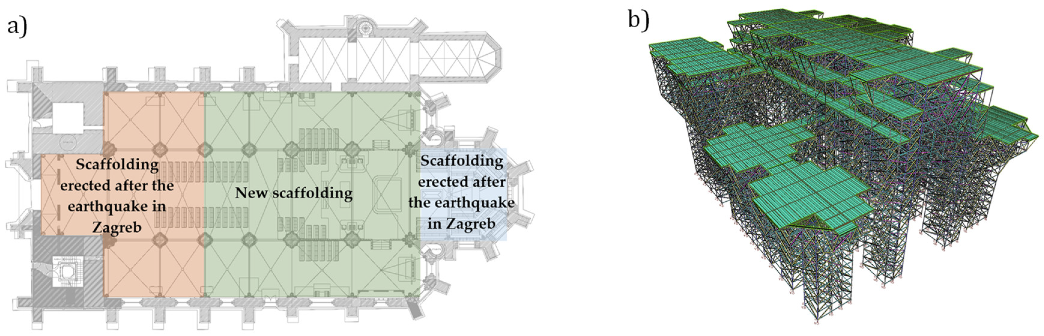
The internal scaffolding serves to restore and strengthen the vaults of the cathedral damaged by the earthquake but also to support the existing vaults until the above-mentioned work is completed [31]. Immediately after the earthquake in March 2020, the interior scaffoldings were erected along the choir and in the apse, but most of the vaults remained without scaffolding; see Figure 4a.
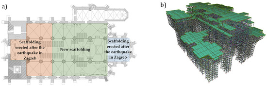
Figure 4.
Internal scaffolding structure: (a) floor plan, (b) numerical 3D model.
The geometry of the new scaffolding was defined using a point cloud model. The modules were selected and adapted to closely align with the geometry of the cathedral, i.e., the working areas were as close as possible to the walls and vaults. The scaffolding supports a total of 12 internal vaults of the cathedral: 4 in the central nave and 8 in the side aisles; see Figure 4a. Cantilevered brackets in the scaffolding system and additional local structures made of tubular scaffolding members are used as required to gain access to the walls and vaults [32].
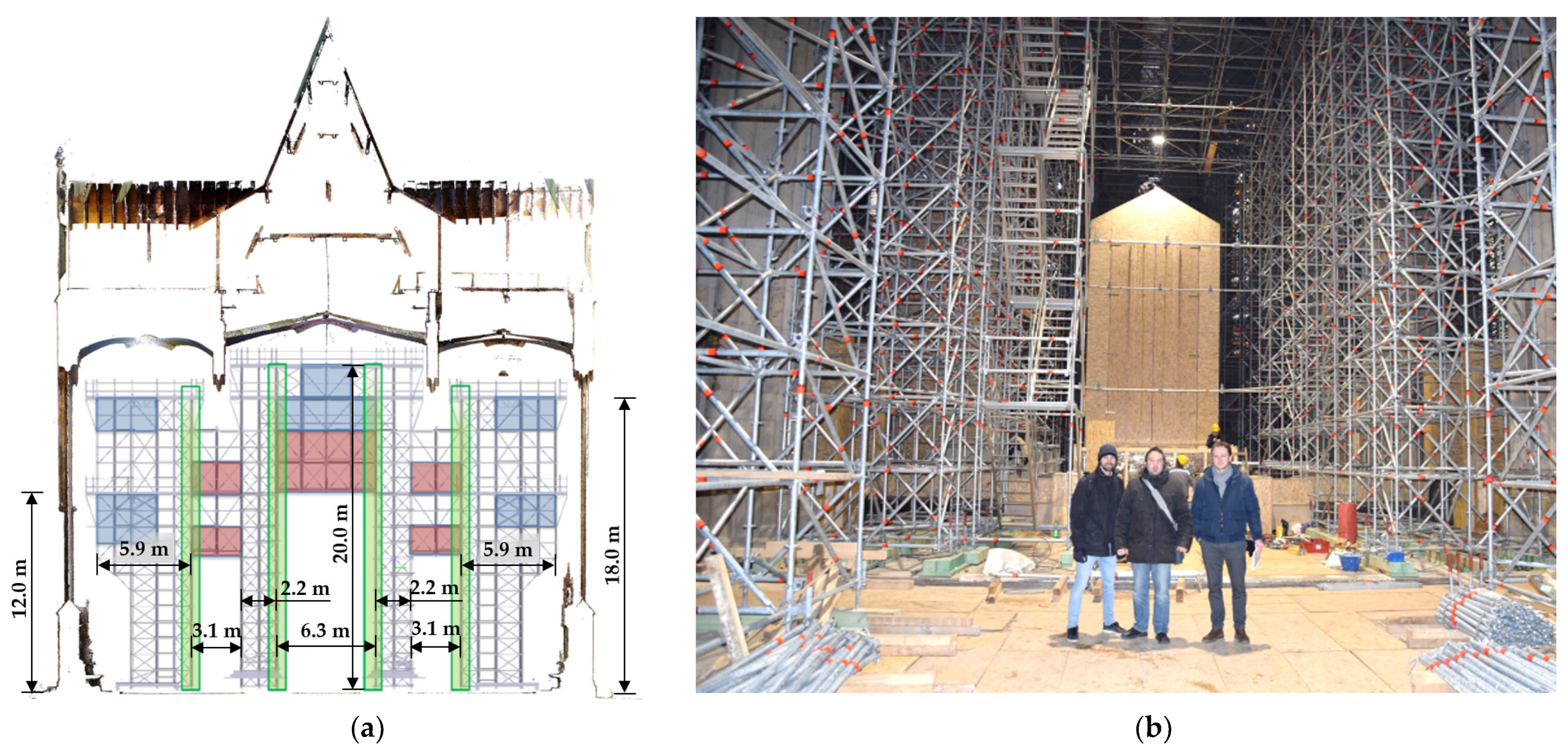
The modular scaffolding consists of truss columns that support the truss girders and form a structure for the assembly of working areas; see Figure 4b. The structure consists of 20 levels, each 1.0 m high. Between the inner rows of the columns, there are truss girders with a span of 6.288 m, and between the inner and outer rows of the columns, there are truss girders with a span of 3.144 m; see Figure 5. Cantilevered trusses with a span of 2.176 m were erected on the outer rows of the columns. The total length of the scaffolding is 32.0 m, and the total width is 28.8 m.
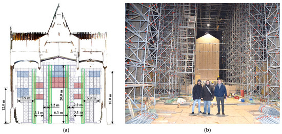
Figure 5.
Internal scaffolding: (a) areas with reinforcement zones, (b) centre section in the final assembly phase.
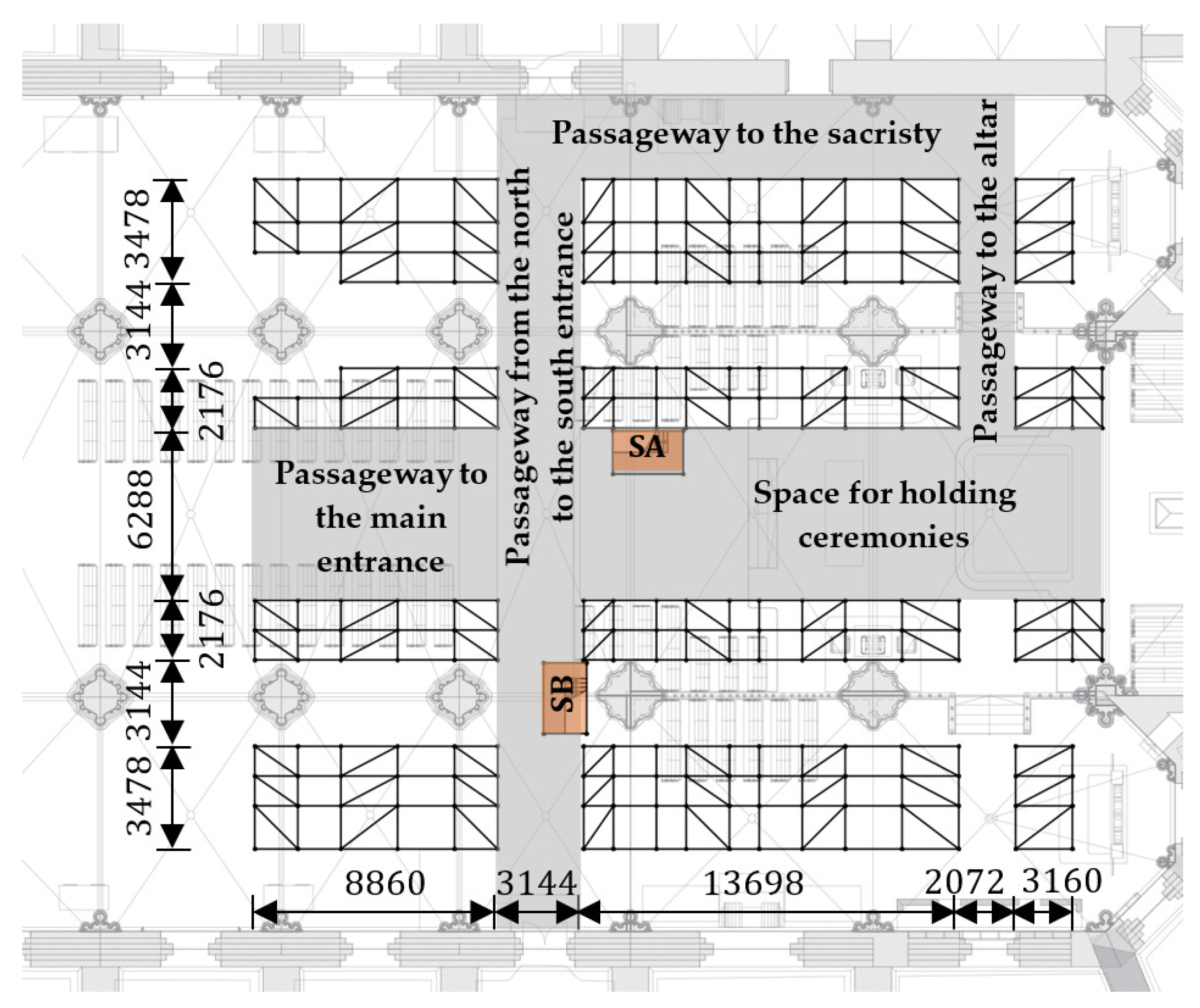
The scaffolding structure is supported by 12 truss columns arranged in four longitudinal rows and consisting of modular scaffolding members. In the floor plan, the columns are arranged to allow horizontal communication of people and equipment on the floor, but also to allow ceremonies to be held in the cathedral for the duration of the works; see Figure 6. A passageway was formed from the main entrance at the front of the cathedral to the main altar and a passageway from the north to the south entrance to bring in cargo and equipment and to evacuate people. There is also a narrow passageway to the sacristy and from the sacristy to the main altar.
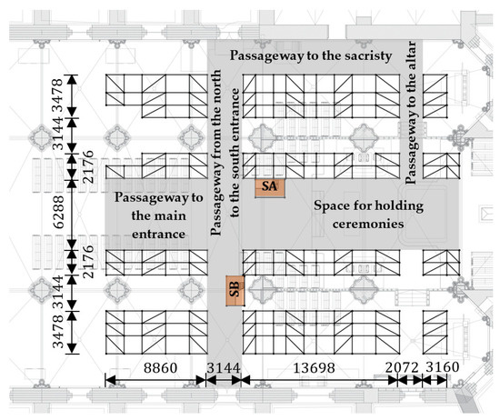
Figure 6.
Horizontal communication inside the cathedral after the scaffolding was erected (section of the scaffolding on level 1; dimensions are given in mm).
The scaffolding has five working areas on levels 12, 18 and 20. The working area under the vaults of the central nave is at a height of +20.0 m above the floor of the cathedral. In the side aisles, the height of the working areas is +18.0 m above the floor for the four vaults closer to the choir and +12.0 m for the other four vaults closer to the apse. Two stairways are provided for access to the working areas: one for access to the areas on the 12th level (Stairway A—SA, Figure 6) and the other for access to the areas on levels 18 and 20 (Stairway B—SB, Figure 6). The usable area of each working area on the 12th level is 125.0 m2, and a walkway was formed to ensure horizontal communication between them. Between the inner rows of columns, the walkway leads over a truss bridge with a span of 6.288 m; see Figure 5. The SA stairway is located next to this bridge structure. The SB stairway, which provides access to the working areas on levels 18 and 20, is located next to the passageway connecting the north and south entrances of the cathedral and next to the stone pillar on which the stone arches or vaults rest; see Figure 6. It was not possible to build a stairway above the 16th level, as the stairway and the stone arch would collide. For horizontal communication on the 16th level, a walkway was created that connects all parts of the 16th level. Communication between the parts of the scaffolding located in the side aisles next to the choir and the part of the scaffolding located under the central nave is made possible by lattice bridges with a span of 3.144 m, on which a walkway is formed. On the 18th level, there are working areas for carrying out work on the vaults in the side aisles, which are closer to the choir. The usable area of each of the working areas on the 18th level is 82.6 m2. A walkway was also created on the 18th level to provide horizontal communication to the part of the scaffolding located in the central nave of the cathedral, i.e., under the working area on the 20th level. The working area on the 20th level is used for work on the four vaults in the nave. The usable area on the 20th level is 244.8 m2. The vertical communication between levels 16, 18 and 20 is established using scaffolding access ladders.
As the internal scaffolding is not laterally supported, all working levels consist of steel platform units. This results in the required horizontal rigidity of the entire structure, which is subject to greater deformations and second-order effects due to its slender members.
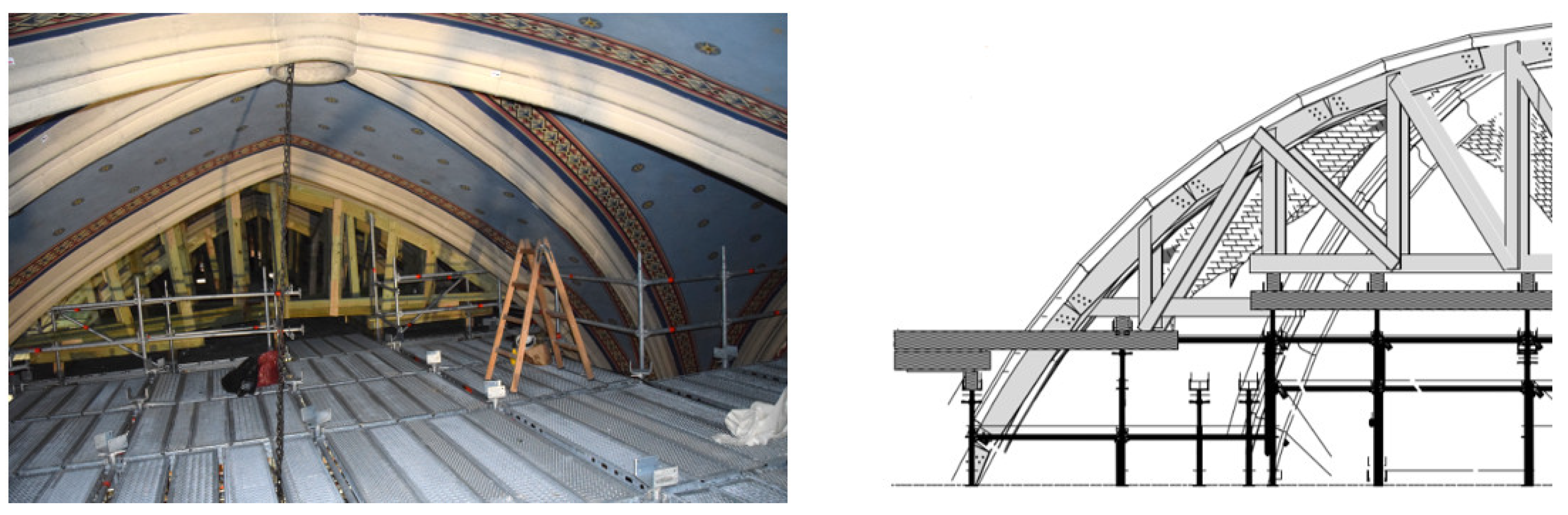
Load-bearing timber structures were erected on the working areas to support the masonry vaults (centring); see Figure 7. Therefore, the scaffolding was designed to bear the load of the masonry vaults and the timber structures supporting them. The timber structure rests directly on the columns of the scaffolding. The evaluation of the geometrically irregular vaults was based on the analysis of the point cloud model, where it was found that the thickness of the vaults varies between 20 and 30 cm.
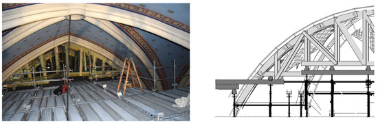
Figure 7.
Working area under the vaults and timber structure (centring) to support the masonry vaults.
In addition to the loads of the masonry vaults, the timber centring and all the relevant loads described in Section 3.1., an additional permanent horizontal load (in both directions) of 1% of the total vertical loads was assumed according to the standard for falsework, EN 12812 [33]. In the absence of the wind load, the scaffolding must be able to withstand the nominal horizontal load acting on all levels, which represents the working operations during use. Accordingly, each working area is loaded with a horizontal service load of 0.30 kN in both directions.
The design of the internal scaffolding led to reinforcements in the areas marked in Figure 5a. The areas marked in green represent double columns, the blue areas are fields where tubular scaffolding members are used (inability to connect more than eight members in one rosette coupler), while the red areas represent truss bridges with prestressed diagonals made of high-strength steel from the manufacturer’s catalogue. In addition, the cantilevered brackets for access to the walls are additionally reinforced with diagonal bracings made of modular scaffolding members due to the high service, i.e., service load. Figure 5b shows a view of the main altar in the final phase of the assembly of the internal scaffolding.
3.3. External Scaffolding
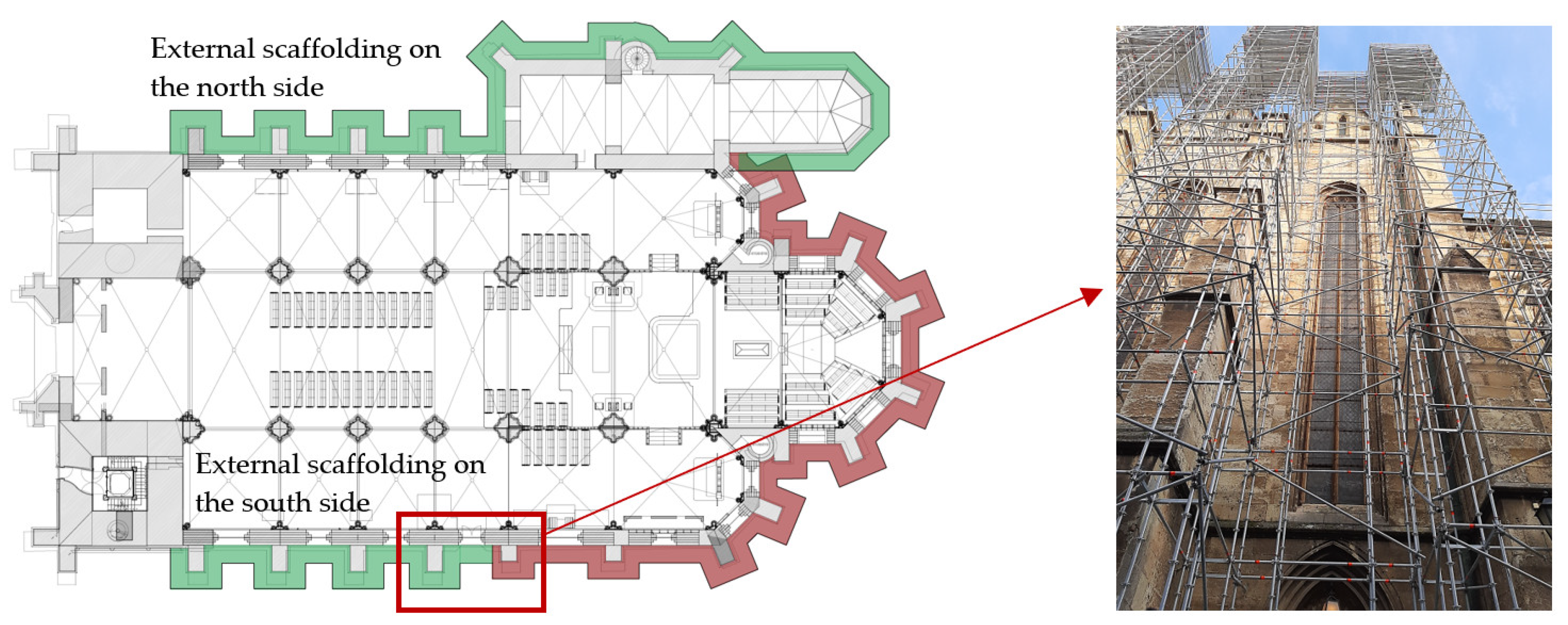
Although the eastern part of the outer walls of the cathedral was scaffolded immediately after the earthquake of 22 March 2020, the need for new scaffolding became apparent due to the inspection, retrofitting and strengthening (prestressing) work on the buttresses; see Figure 8.
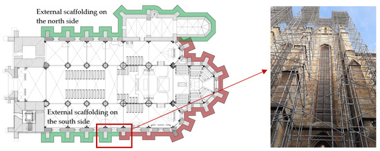
Figure 8.
Structure and position of the external scaffolding (the position of the scaffolding erected after the earthquake in Zagreb is marked in red; the position of the new scaffolding is marked in green).
The façade scaffolding structure on the south side consists of 16 levels, each 2.0 m high; see Figure 9a. The scaffolding was erected around the perimeter of the south façade of the cathedral and includes five buttresses that were damaged during the earthquake [34]. The total length of the scaffolding is 29.5 m, the total width is 3.5 m, and the height is 32.0 m. The scaffolding structure on the north side consists of 16 levels, each 2.0 m high; see Figure 9b. The north façade of the cathedral is scaffolded around five buttresses that were damaged in the earthquake, as well as the outer walls of the sacristy. The total length of the scaffolding is 52.9 m, the total width is 11.6 m, and the height is 32.0 m.
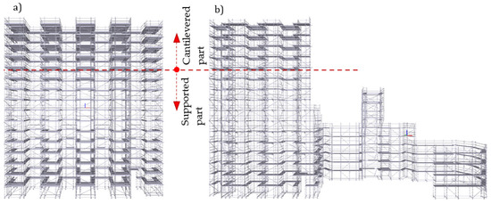
Figure 9.
External scaffolding: (a) south side of the cathedral, (b) north side of the cathedral.
Both scaffoldings are braced in both directions with vertical bracings arranged in a ‘zig-zag’ pattern of tubular scaffolding members connected by swivelling couplers. Given the height and the wind acting on the scaffolding, horizontal anchoring in the walls of the cathedral is essential.
The anchoring is achieved with galvanised eyebolts, which are placed in the joints between the stones. A chemical injection mortar is required in the joint in which the screw is anchored in order to achieve sufficient load-bearing capacity of the bolt. The maximum tensile force at the anchoring eyebolt was around 15 kN for both external scaffoldings. The geometry of the outer wall and the position of the stained-glass windows were taken into account when anchoring the bolts. Above level 12 (+24.0 m above the ground), it was not possible to anchor the scaffolding structures to the walls due to the geometry of the outer wall of the cathedral. Consequently, the scaffolding structures are cantilevered from level 12 to the top of the scaffolding at level 16, i.e., 8.0 m. Each level of the scaffolding also represents a potential work area. The working areas are used for horizontal communication and for carrying out retrofitting and strengthening work on structural and non-structural parts of the cathedral. Up to the 12th level, the floor consists of aluminium platform units, while from the 12th floor up to the top, steel platform units were installed due to the expected demanding work to prestress the buttresses. Scaffolding access ladders are used to access the working areas.
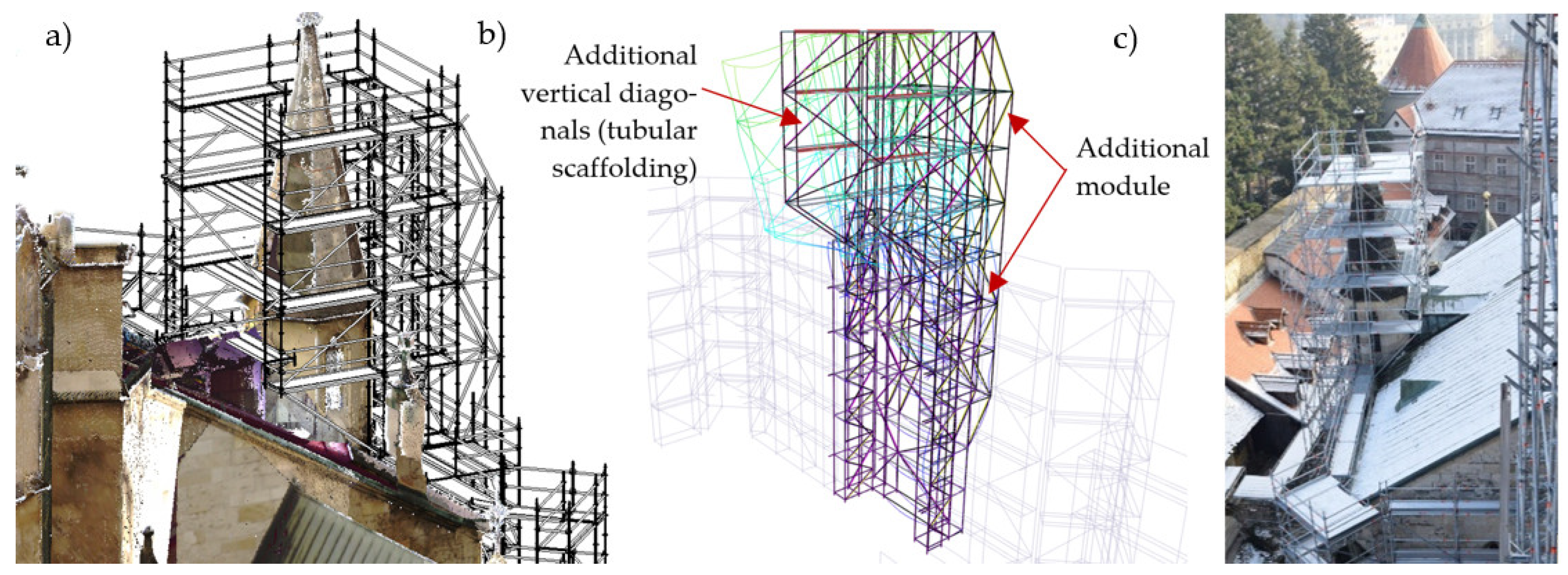
As it was not possible to support part of the scaffolding around the sacristy tower, the scaffolding had to be cantilevered at this point; see Figure 10a. The numerical analysis, as seen in Figure 10b, indicated very large vertical deflections under service load conditions. Such a solution required the reinforcement of the façade scaffolding on the opposite side, which was solved by installing an additional module to absorb additional forces from the eccentricity of the service load for the restoration of the sacristy tower. Vertical bracing members (tubular scaffolding) were also added to the cantilevered part [35]. Figure 10c shows the assembled scaffolding around the sacristy tower. It should be noted that, in addition to installing reinforcement elements to that part of the structure, the service load was reduced from 3.0 kN/m2 to 2.0 kN/m2 in agreement with the contractor.
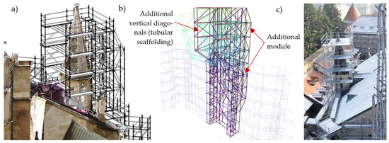
Figure 10.
Part of the cantilevered scaffolding around the sacristy tower (north side of the cathedral, sacristy): (a) spatial scan + BIM model; (b) numerical model; (c) erected scaffolding.
3.4. Tower Scaffolding
3.4.1. State of the Old Tower Scaffolding
The cathedral’s retrofitting project includes, among other things, the dismantling of the upper levels of the stone towers damaged by the earthquake, their reconstruction with new stone blocks and adequate seismic strengthening. In order to fulfil this task, new scaffolding is to be erected up to the full height of the cathedral’s two towers. However, old tubular scaffolding was already in place on the south tower at a height of +41.1 m to +63.0 m, with access to this scaffolding provided from the north side of the cathedral using an Alimak elevator with a load capacity of 1500 kg and an access path at a height of +45.0 m.
An inspection of the old tubular scaffolding structure on the south tower [36] revealed numerous deficiencies in terms of the durability of the scaffolding elements and the steel platform, mainly in the form of corrosion, local mechanical damage and global damage caused by the 2020 earthquake, as shown in Figure 11. There was also the problem of connecting the old scaffolding on the south tower with the new scaffolding intended for the restoration of the cathedral’s towers (urgent removal of the damaged parts of the tower and construction of new ones). The interaction between the two systems, the old tubular scaffolding and the new modular scaffolding, which differ in geometry and construction technology, led to a series of additional problems (adequate connection of the different geometries of the two scaffoldings, load-bearing capacity issues of the old tubular scaffolding after the upgrade, etc.), which are analysed in detail in [36].
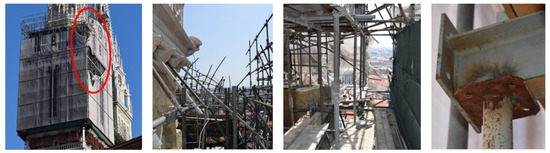
Figure 11.
Damage on the old scaffolding structure on the south tower of Zagreb Cathedral [36].
With the assumptions made in the numerical model, which mainly concern the old tubular scaffolding geometry, the bracing on the cathedral tower, the connection between the two scaffolding systems and the effects of wind and earthquakes, it was found that about 25% of the tubular scaffolding members and platform does not have sufficient load-bearing capacity. Based on the issues related to the connection of the two scaffolding systems, which are described in detail in [36], it could be concluded that both the old tubular scaffolding and the old platform were not reliable for a possible extension to the top of the tower.
Another problem that arose was related to the construction technology, in particular vertical communication from the ground to the top of the scaffolding. The erection of the new scaffolding on the north tower includes the assembly of an elevator for vertical communication from the ground to the highest working area. As the work on the new scaffolding requires the removal of heavy stone blocks and their transport to the ground, the assembly of a new elevator was necessary. Among several options considered for vertical communication, the assembly of two new independent elevators from the ground to the top of the scaffolding on the south side of the south tower and the north side of the north tower was the only operational solution that met the requirements of the dismantling and reconstruction of the towers. By adopting this proposal, the old Alimak elevator and the access path with the bridge connecting the north and south towers lost their function regarding the restoration of the towers.
Based on the analyses carried out, it was decided that the old tubular scaffolding on the south and north towers was completely removed [37]. A new scaffolding was designed for the north and south towers including two new independent elevators to enable communication over the entire height of the new scaffolding.
3.4.2. The New Tower Scaffolding
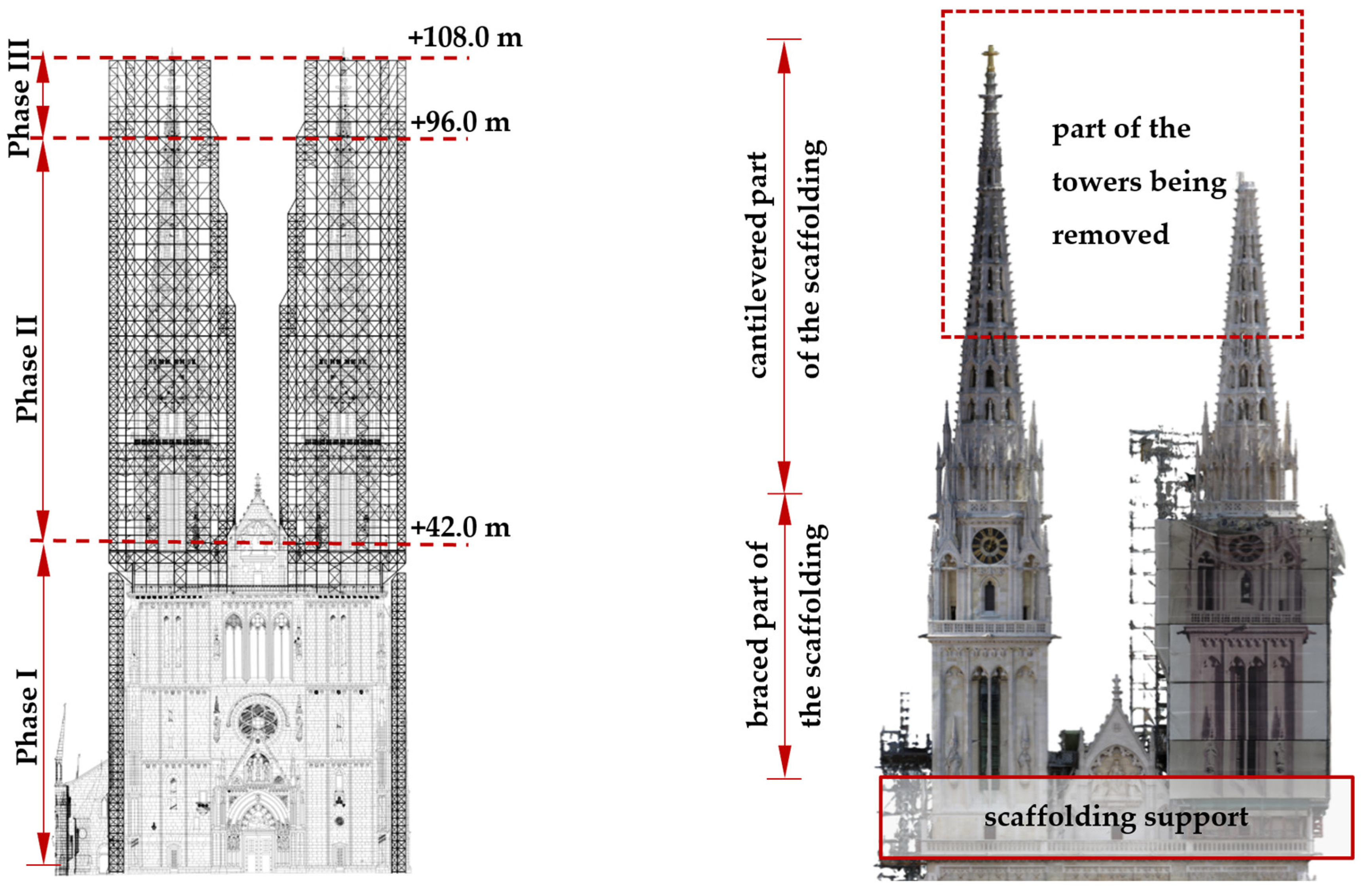
The new scaffolding for the restoration of the towers on the west side of the cathedral consists of two independent, multidirectional modular scaffolding structures anchored to steel platforms at the base of the towers [28]. Vertical communication of personnel and equipment is facilitated by two independent elevators on the outside of the towers. For the dismantling and reconstruction works of the towers, each tower is equipped with an overhead crane at the top, whose main girder with a load capacity of one tonne covers the ground plan of the stone towers. The erection of the tower scaffolding is planned in three phases, as shown in Figure 12:

Figure 12.
Phases of scaffolding erection (illustration on the north tower).
- Phase I included the construction of the platform P1 at a height of +36.8 m to +42.0 m, which supports the new modular scaffolding, and the erection of the scaffolding to support the elevator from ground level (±0.0 m) to +39.2 m, together with an elevator and its substructure.
- Phase II comprised the erection of the new scaffolding from platform P1 (+42.0 m) to the current height of the towers (+96.2 m). During successive assembly, the scaffolding is horizontally braced to the towers up to a height +66.2 m.
- Phase III follows the reconstruction and strengthening of the cathedral towers. The scaffolding continues from the existing Phase II structure from +96.2 m to the top of the newly strengthened tower at +106.2 m, with horizontal braces being added to the towers every three levels from +74.2 m.
The scaffolding modules were selected and adapted so that the internal dimensions closely follow the tower’s ground plan and the working areas are as close as possible to the tower façade. Within the main scaffolding, cantilevered brackets and additional localised structures made of tubular scaffolding components are used to move closer to the tower façade.
The multidirectional modular scaffolding to support the elevator installed in Phase I starts at ground level (±0.0 m) and extends to +39.2 m to reach the platform P1. This scaffolding consists of 39 levels, each 1.0 m high. The self-supporting elevators, each with a load-bearing capacity of two tonnes, allow the continuous vertical movement of personnel and equipment from the ground to the top of the towers, i.e., to the top of the scaffolding in Phase III (+106.2 m).
The supporting structure of the elevator measures 5.2 m in depth, 1.8 m in width and 39.2 m in height. The main elements are tubes with a diameter of 48.3 mm from the manufacturer’s catalogue. Horizontal bracing is provided on each level and vertical bracing on all outer planes, as illustrated in the characteristic module; see Figure 13. This part of the scaffolding is not intended for the personnel movement or elevator stations, so no platform units have been installed. At heights +3.2 m, +9.2 m, +16.2 m, +25.2 m and +34.2 m, horizontal anchoring to the cathedral is achieved using four scaffold tubes (CHS 48.3 × 4, S 235 JR) with end plates and bolts. Anchoring to the cathedral wall was carried out using chemically injected threaded rods (4 × M16, grade 10.9).
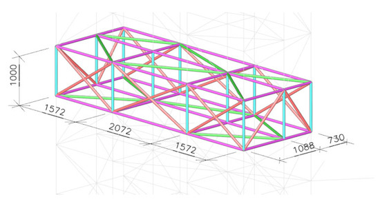
Figure 13.
Characteristic module of the scaffolding structure for elevator support (dimensions in mm).
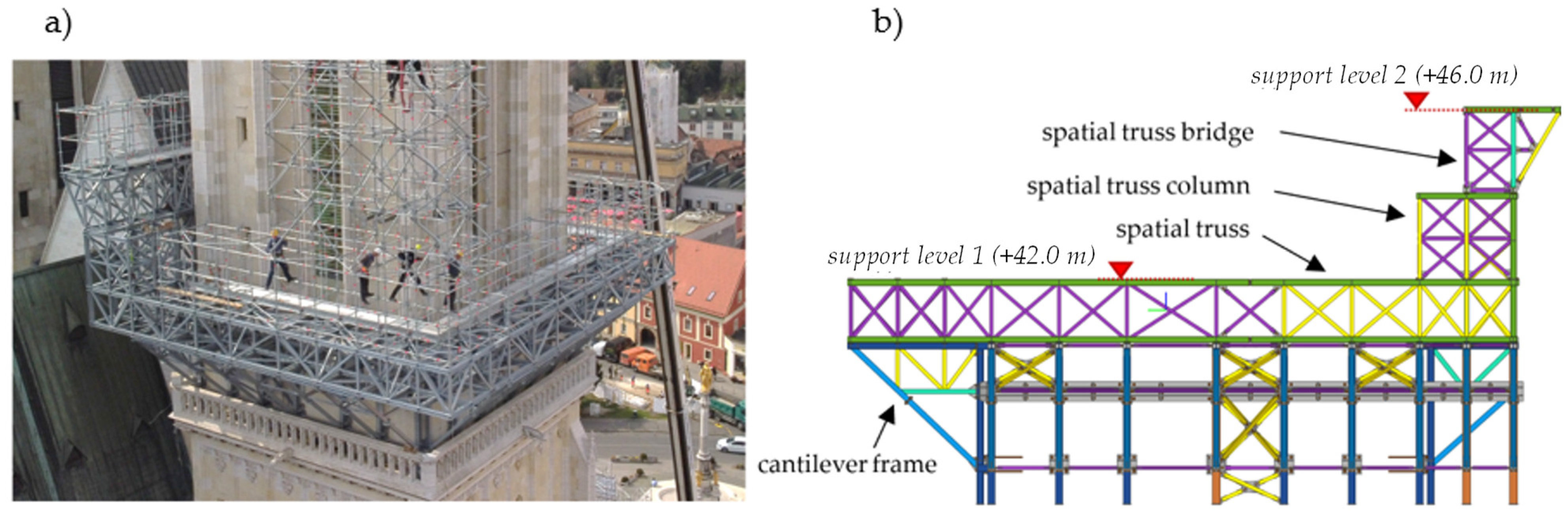
The primary platform P1, erected during Phase I, is a steel spatial truss, as seen in Figure 14a, which supports the scaffolding on two levels. The platform extends over a height of +36.8 m to +46.0 m. The ground plan dimensions of level one at a height of +42.0 mare 15.4 m × 16.5 m. Level two is located at +46.0 m and has a ground plan dimensions of 16.5 m × 2.2 m. The reason for the erection of two platform levels arises from the geometry of the cathedral. The roof between the towers (the tympanum roof), as seen in Figure 12, was an obstacle. This obstacle could only be overcome by raising the southern part of the platform on the north tower and the northern part of the platform on the south tower.
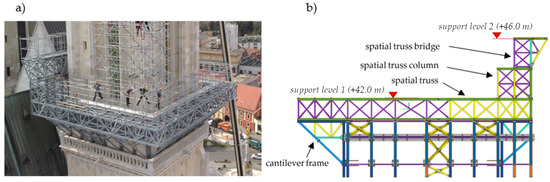
Figure 14.
Structure of platform P1: (a) erected structure; (b) section.
The structure of platform P1 consists of various types of cross-sections, mainly hot-rolled HEA, and hot-finished square tube profiles, all made of European steel grade S 355 J2. All bolted connections used to join the assembly units are hot-dip galvanised, grade 10.9, in accordance with EN 14399 [38].
The platform P1 can be divided vertically into four levels; see Figure 14b. The first level consists of cantilevered frames, the second level consists of spatial trusses, the third level consists of spatial truss columns, and the final, fourth level, consists of a spatial truss bridge structure spanning between the truss columns.
The entire platform is anchored to the cathedral with cantilever frames consisting of a column, a cantilevered truss and a strut, each part forming an assembly unit; see Figure 15. All columns are 3.7 m high and are supported vertically by the cathedral’s gallery at a height of +36.8 m. The cantilevered truss has an axial height of 1.1 m and an axial length of 3.0 m. The truss is connected to the column at one end through bolted connections at the top and bottom chords and is supported at the other end by a strut bolted to the column 0.9 m above the column base. This allows the outer edge of the truss to be supported without having to remove the stone railing of the cathedral gallery. The platform includes a total of 25 cantilever frames.
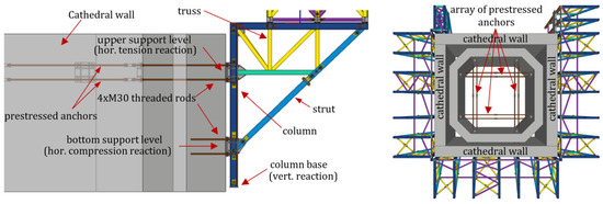
Figure 15.
Anchoring of steel frames into/through the cathedral wall.
Each frame is typically anchored at three points to the stone structure of the cathedral; see Figure 15. The vertical load is transferred through the column base, which rests on the stone floor of the gallery with a 50 mm thick elastomeric pad. The horizontal load is transferred at two levels of supports on the columns. The lower support level is located at the connection between the strut and the column, while the upper support level is located at the connection between the bottom chord of the truss and the column. Only the compression reaction of the strut and the horizontal shear reaction are transferred to the cathedral wall in the lower support level through mortar-injected threaded rods (4 pcs, M30, grade 10.9). The upper support level has a similar detail to the lower level, with the difference that six cantilever frames are also tension-anchored to the walls. At these points, the holes for the threaded rods are drilled through the entire thickness of the cathedral tower (both opposite walls). Steel anchor plates are attached to the inner side of the walls. The rods extending from these details continue inside the tower, forming an array of prestressed anchors; see Figure 15. It is important to note that only the anchors embedded in the two opposite walls transfer the tensile force. This solution was chosen because the anchoring forces in the design were almost 300 kN, which is a considerable value given the condition of old masonry walls. In this way, even if the transfer of anchoring forces into the masonry walls fails, the steel platform can anchor itself through a series of prestressed anchors.
The columns of the cantilever frames are made of HEA 160 and HEA 180 profiles. The cantilever trusses consist of various hot-finished tubular profiles. The top chord of the trusses is fabricated from HEA 160 profiles, while the bottom chord is formed from SHS 100 × 100 × 5. The truss diagonals are made of SHS 80 × 80 × 5 tubular members, and the strut of the frame is made of SHS 120 × 120 × 6 profiles. Between the cantilever frames, there are also bracings made of SHS 80 × 80 × 5 tubular profiles; see Figure 15.
A spatial hexagonal truss is supported by the cantilever frames; see Figure 16. The external dimensions of the truss are 16.6 × 15.6 × 1.5 m. The truss grid is aligned with the scaffolding modules in order to transfer the scaffolding reactions to the truss nodes. The top and bottom chords of the truss are made from hot-rolled HEA 140 profiles. For all horizontal trusses, the HEA 140 cross-section was chosen for the top chord to provide sufficient space to accommodate 120 mm wide scaffold base details. The diagonals are made from hot-finished SHS 70 × 70 × 4 and SHS 80 × 80 × 5 tubular profiles. The horizontal and vertical diagonals of adjacent planes are arranged in opposite directions in order to achieve a spatial X-arrangement of the diagonals and thus a higher load-bearing capacity. The same principle was applied to the spatial trusses of the platform on the third and fourth levels. The truss is assembled from five assembly units, which are bolted together on site using 4 x M16 grade 10.9 bolts.
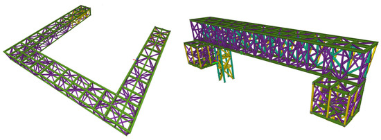
Figure 16.
The bottom truss of the platform structure and the truss columns with the spatial bridge truss structure.
The third and fourth levels of the platform P1 consist of spatial truss columns (level three) and a spatial truss bridge (level four), which support the side of the scaffolding facing the adjacent tower; see Figure 16. The truss columns are made of vertical members fabricated from SHS 80 × 80 × 5 or SHS 100 × 100 × 5 profiles. At the edges of the columns facing the roof of the cathedral, the vertical members of the spatial truss columns are made of stronger HEA 140 cross-sections, as these vertical members take the majority of the vertical reactions of the truss bridge structure. The diagonals of the columns are made exclusively from hot-finished SHS 70 × 70 × 4 or SHS 80 × 80 × 5 tubular profiles. The top spatial truss bridge rests on these truss columns. The chords of the truss are made of HEA 140 profiles and the diagonals of SHS 100 × 100 × 5 and SHS 70 × 70 × 4 tubular profiles. The struts that support the top chord of the truss facing the adjacent tower are made of hot-finished SHS 80 × 80 × 5 tubular sections. The truss bridge is divided into two assembly units, which are bolted to the top chord with 6 x M16 bolts and to the bottom chord with 8 x M16 bolts.
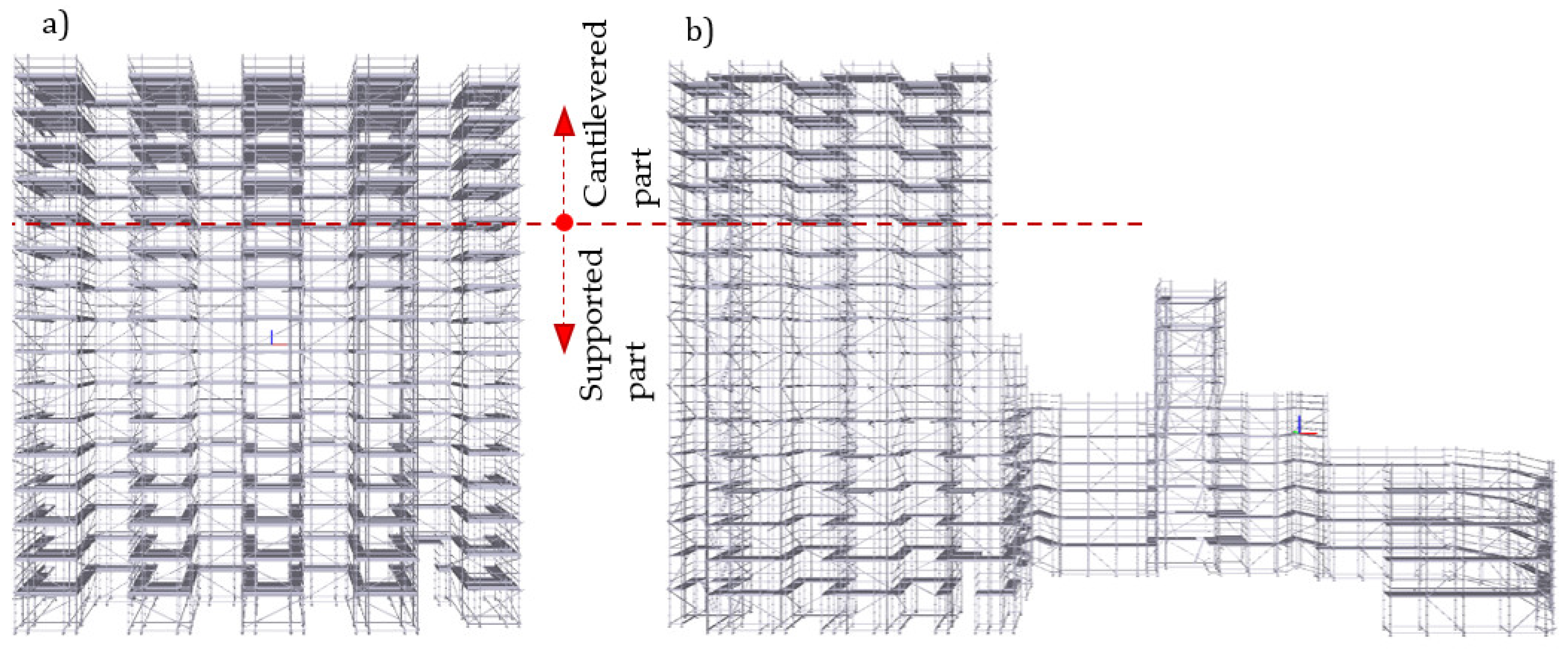
The scaffolding structure erected in Phases II and III, as seen in Figure 12, also consists of members of the modular multidirectional façade scaffolding. The scaffolding is installed on the main platform P1 at a height of +42.0 m, with additional heights at +44.0 m and +46.0 m, reaching up to +96.2 m in Phase II and +106.2 m in Phase III. The scaffolding tapers in height, following the contours of the tower, and can be divided into five characteristic sections.
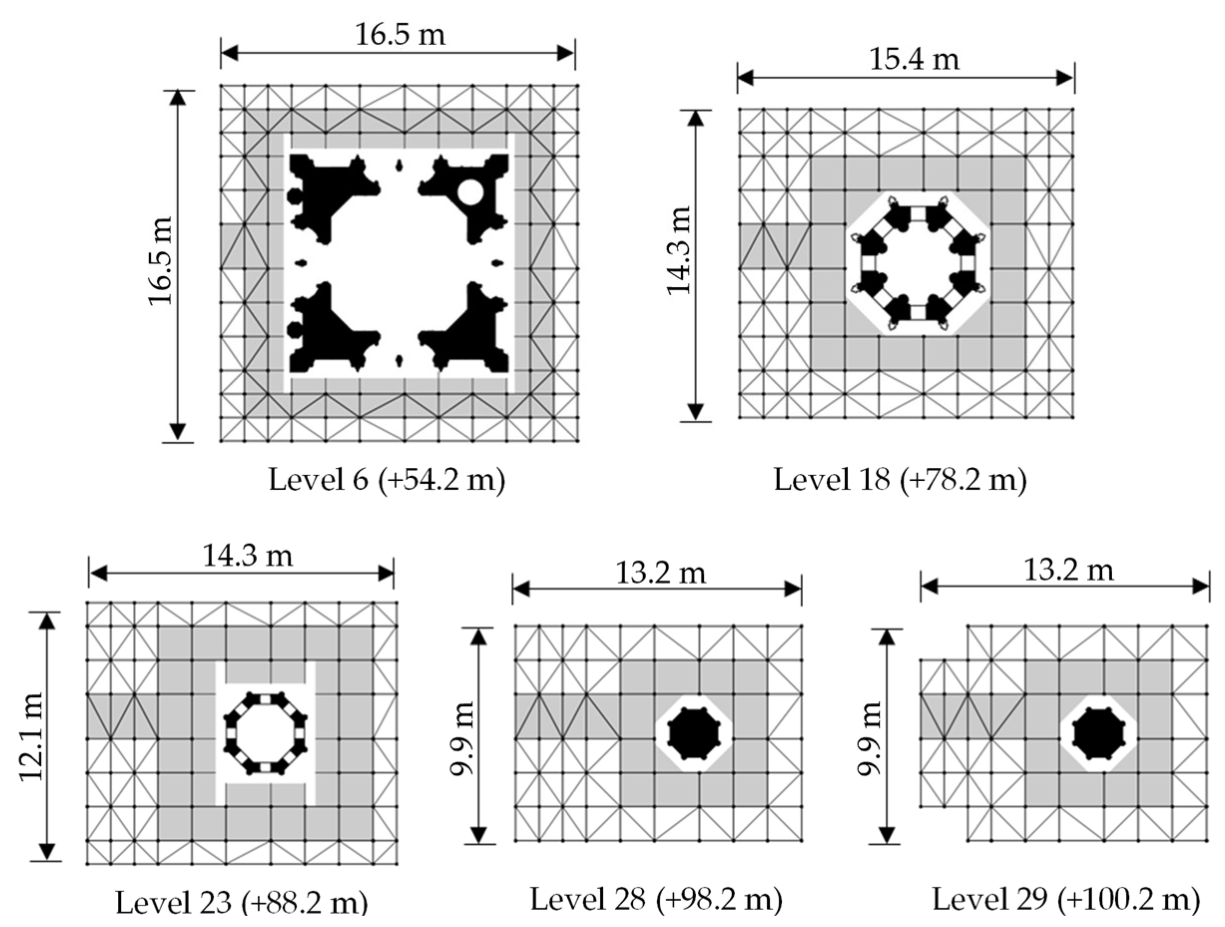
In the first section, from the top of the base jacks on platform P1 (+42.2 m) to a height of +74.2 m (levels 0 to 16), the width of the levels is 16.460 m in both directions. In the second section, from +74.2 m to +86.2 m (levels 17 to 22), the ground plan dimensions of the scaffolding are 15.372 × 14.284 m. In the third section, from +86.2 m to +96.2 m (levels 23 to 27), the plan dimensions are 14.284 × 12.108 m. In the fourth section, from +96.2 m to +98.2 m (level 28), the ground plan dimensions are 13.196 × 9.932 m. In the highest section, from +98.2 m to +106.2 m (levels 29 to 32), the ground plan dimensions are 13.196 × 6.788 m. Figure 17 shows the plan view of the characteristic levels with their dimensions at the points where the scaffolding tapers. The shaded areas represent the working areas with platform units.
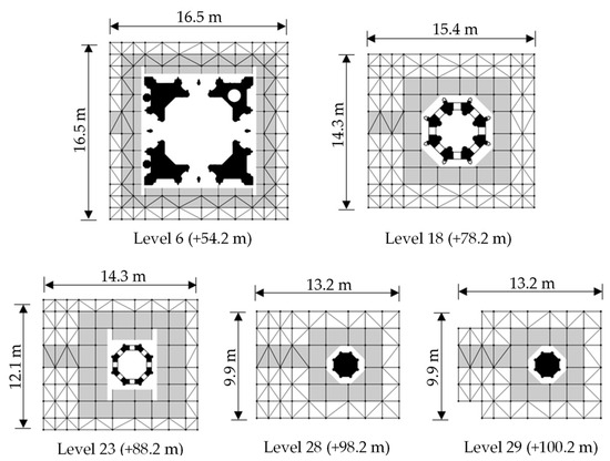
Figure 17.
Characteristic ground plans of the tower scaffolding.
The main elements of the tower scaffolding are round tubes with a diameter of 48.3 mm, as specified in the manufacturer’s catalogue. CHS 48.3 × 4 profiles from tubular scaffolding were chosen for the vertical bracings, as no more than eight members can be connected at a single node. The vertical braces are made of S 235 JR grade steel and are connected with rigid and/or swivel couplers.
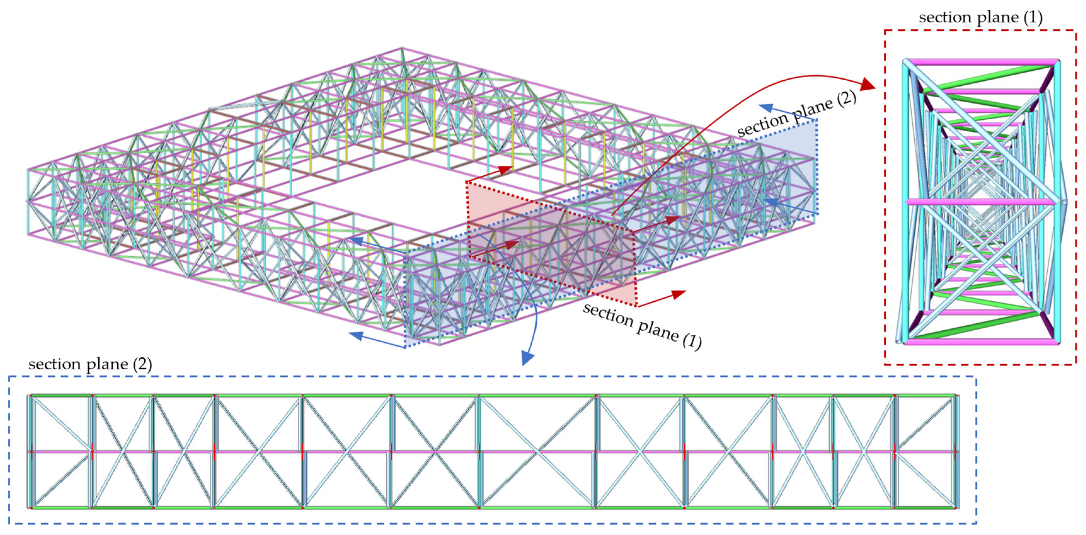
The module heights are 2000 mm, with ground plan dimensions of 1088 mm, 1572 mm and 2072 mm, while the length of the cantilevered module is 730 mm. In general, the scaffolding around the tower forms a spatial truss structure with a reinforced edge layer (additional horizontal members with corresponding vertical members at mid-height of each level); see Figure 18. The horizontal and vertical diagonals in neighbouring bays are arranged in opposite directions in order to achieve a spatial X-arrangement of the diagonals. This system is highly favourable for resisting horizontal displacements due to wind or seismic loads, especially in this case where the structure with a span of 40.0 m will be cantilevered for most of its service life. In the outer bays there are no platform units at any level, so all the external horizontal bays are filled with CHS 48.3 × 2.7 horizontal diagonals to provide lateral support to the columns at mid-height. At the levels where the tower scaffolding is anchored to the towers, the horizontal bays are reinforced with platform units and with horizontal bracings made of CHS 48.3 × 4 scaffolding tubes. Aluminium platform units are laid on all levels. Vertical communication of personnel is facilitated by an elevator and ladders integrated into the scaffolding system.
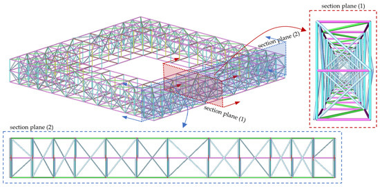
Figure 18.
Characteristic level of the tower scaffolding with reinforced bays.
The scaffolding structure of Phase II is horizontally anchored at heights +48.2 m, +50.2 m, +52.2 m, +54.2 m, +58.2 m, +60.2 m, +62.2 m, +64.2 m and +66.2 m. Higher levels cannot be anchored horizontally as the tower was severely damaged, and a significant part of the tower will be dismantled. Consequently, the structure of Phase II from +66.2 m to its top at +96.0 m is not horizontally anchored; see Figure 12. This results in a cantilevered structural system with a height of almost 40 m, which posed significant design challenges, such as high axial forces in the columns and vertical bracings. Considering that the modular scaffolding system is primarily designed to be anchored to the structure being worked on, this application of such scaffolding represents a significant technical achievement. The scaffolding is anchored to the towers using tubes connected with gusset plates to end plates anchored to the wall of the cathedral with 4 × M16 or 4 × M20 grade 10.9 threaded rods. The threaded rods are anchored at a depth of 30 cm using a chemical anchoring agent. The tube is connected to the gusset plate with a single M24, grade 10.9 bolt, allowing it to rotate around the vertical axis and adjust the support position on site. In addition, a wedge made of CHS 88.9 × 5 tube profile (150 mm in length) or CHS 48.3 × 4 tube profile (100 mm in length) is used to transfer shear forces. The maximum anchoring forces occurred at the highest anchoring level (+66.2 m) with a magnitude of 55 kN for the tensile forces and 86 kN for the shear forces. The support tubes are connected to the scaffolding using special couplers on the scaffolding verticals. These couplers are cold formed from 5 mm thick steel plates, with the inner radius corresponding to the outer radius of the vertical tubes. A steel plate with slotted holes is attached to the couplers allowing for vertical movement of the scaffolding relative to the cathedral tower.
The analysis results showed the need for reinforcement measures for the scaffolding. The modular vertical bracings were replaced by scaffolding tube members, X-type bracings were added in the outer and first inner planes, and on levels 1–9, the outer and centre columns were braced at mid-height (every 1.0 m) in both directions. In addition, the inner columns were replaced with double columns from the manufacturer’s catalogue; see Figure 18 [39].
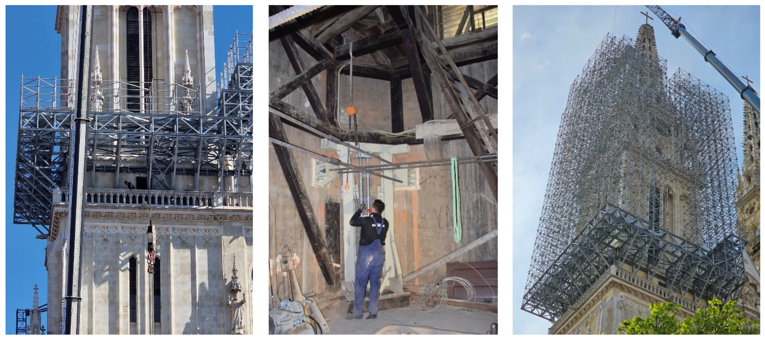
Some specific phases of the assembly of the tower scaffolding on the north tower are shown in Figure 19. The photo on the left shows the steel platform P1 and the first level of the scaffolding that was erected on the north tower. The photo in the centre shows the interior of the tower during the assembly of the anchorages after the mounting of the corner steel structures supporting the wooden bell structure in the north tower. The photo on the right shows the scaffolding on the north tower during the assembly phase. Further levels were added later, as were the aluminium platform units and the elevator for vertical communication.

Figure 19.
Assembly of the tower modular scaffolding on the north tower of the cathedral.
4. Conclusions
The retrofitting project of Zagreb Cathedral after the 2020 earthquakes achieved significant technical milestones, emphasising the crucial role of innovative scaffolding design in extremely short periods. General conclusions and solutions from this project were made:
- By stabilising damaged parts of the cathedral and preventing further collapse, the scaffolding played a critical role in preserving the cathedral’s historical and cultural integrity.
- The scaffolding enabled detailed structural assessments and inspections, allowing engineers and restorers to identify and address specific areas of concern more effectively.
- Modular scaffolding allowed for faster and more efficient assembly and disassembly, crucial given the urgency of the restoration and retrofitting work. Despite lower geometric adaptability, precise planning using point cloud models allowed modular scaffolding to fit complex geometries. This approach is replicable in other projects requiring rapid deployment and high safety standards.
- Unique anchoring methods for attaching scaffolding to thick stone towers walls can be easily adapted and applied to similar restoration projects.
- For such complex structures, nonlinear analysis was crucial in predicting the real behaviour of the scaffolding and ensuring its stability and effectiveness. This analysis helped in understanding of real behaviour, that is, how the scaffolding would respond under various loads and stresses, particularly during wind actions.
Due to the cathedral’s complex geometry, the scaffolding design was based on spatial scans (point clouds) processed during the design phase. Without these modern techniques, it would be almost impossible to design and assemble the entire scaffolding in an extremely short period of just a few months. The tower scaffolding on the west side, which received significant media coverage, featured exceptionally high cantilevers. Although not visible to passers-by, the internal scaffolding was crucial for supporting and restoring the cathedral’s damaged vaults. Overall, the modular scaffolding structures ensured immediate stability and restoration, setting a precedent for future restoration efforts of historical monuments and highlighting the importance of tailored engineering solutions in heritage conservation.
Author Contributions
This paper was accomplished based on collaborative work of the authors. Conceptualization, D.S.; methodology, D.S.; software, I.Č. and A.V.; validation, all authors; formal analysis, all authors; resources, D.S. and D.L.; data curation, all authors; writing—original draft preparation, D.S., I.Č. and A.V.; writing—review and editing, D.S. and D.L.; visualization, all authors; supervision, D.S. and D.L.; funding acquisition, D.S. All authors have read and agreed to the published version of the manuscript.
Funding
This research received no external funding.
Data Availability Statement
The original contributions presented in the study are included in the article, further inquiries can be directed to the corresponding author.
Conflicts of Interest
The authors declare that there are no conflicts of interest regarding the publication of this paper.
References
- Šimunić, I.; Šimunić-Buršić, M. Vault of the Sacristy of Zagreb Cathedral. Prost. Znan. Časopis Za Arhit. I Urban. 2015, 23, 344–353. (In Croatian) [Google Scholar]
- Foretić, D. Thirty Years of Renovation of Zagreb Cathedral. Klesar. I Graditelj. 2019, 29, 34–53. [Google Scholar]
- Šavor Novak, M.; Uroš, M.; Atalić, J.; Herak, M.; Demšić, M.; Baniček, M.; Lazarević, D.; Bijelić, N.; Crnogorac, M.; Todorić, M. Zagreb earthquake of 22 March 2020—Preliminary report on seismologic aspects and damage to buildings. Građevinar 2020, 72, 843–867. [Google Scholar]
- NN 75/2020: Tehnički Propis o Izmjeni i Dopunama Tehničkog Propisa za Građevinske Konstrukcije; Government of Croatia: Zagreb, Croatia, 2022; (In Croatian). Available online: https://narodne-novine.nn.hr/clanci/sluzbeni/2020_07_75_1448.html (accessed on 31 May 2024).
- Skejić, D.; Lukačević, I.; Ćurković, I.; Čudina, I. Application of steel in refurbishment of earthquake-prone buildings. Građevinar 2020, 72, 955–966. [Google Scholar]
- Zagrebačka Katedrala: Izvješće o Oštećenjima, Obavljenim Radovima i Planovima Obnove Zagrebačke Katedrale. (In Croatian). Available online: https://katedrala.hr/hr/izvjesce-o-ostecenjima-obavljenim-radovima-i-planovima-obnove-zagrebacke-katedrale/749 (accessed on 31 May 2024).
- Lazarević, D.; Gidak, P.; Šamec, E.; Jaguljnjak Lazarević, A.; Fresl, K. Seismic Analysis of Zagreb Cathedral—Current State. Struct. Anal. Hist. Constr. SAHC 2023, 1, 918–928. [Google Scholar]
- Šamec, E.; Gidak, P.; Jaguljnjak Lazarević, A.; Oreb, J. On the Selection of Distinct Element Method for Numerical Analysis of Zagreb Cathedral. In Proceedings of the 10th ICCSM International Congress of Croatian Society of Mechanics, Pula, Croatia, 28–30 September 2022. [Google Scholar]
- Gidak, P.; Šamec, E.; Fresl, K.; Lazarević, D. Geometry Generation and Modelling of Non-Standard Cross Vaults. In Proceedings of the IASS 2022 Symposium Affiliated with APCS 2022 Conference, Beijing, China, 19–22 September 2022. [Google Scholar]
- Romero-Sánchez, E.; Requena García de la Cruz, M.V.; Morales-Esteban, A. Seismic Assessment of Historic Complex Towers. The Case Study of the Giralda Tower. COMPDYN 2023. In Proceedings of the 9th ECCOMAS Thematic Conference on Computational Methods in Structural Dynamics and Earthquake Engineering, Athens, Greece, 12–14 June 2023; Papadrakakis, M., Fragiadakis, M., Eds.; pp. 5191–5201. [Google Scholar]
- Bayraktar, A.; Hökelekli, E.; Şermet, F.; Mosallam, A.S. A FRCM technique for strengthening of masonry domes against near-fault pulse-like vertical excitations. Eng. Fail. Anal. 2024, 163, 108478. [Google Scholar] [CrossRef]
- Requena García de la Cruz, M.V.; Romero-Sánchez, E.; Morales-Esteban, A.; Fernández-Pérez, N. A Model for the Structural and Seismic Assessment of the Mosque-Cathedral of Cordoba. COMPDYN 2023. In Proceedings of the 9th ECCOMAS Thematic Conference on Computational Methods in Structural Dynamics and Earthquake Engineering, Athens, Greece, 12–14 June 2023; Papadrakakis, M., Fragiadakis, M., Eds.; pp. 5179–5190. [Google Scholar]
- 3DEC 7.0 Documentation. Available online: http://docs.itascacg.com/3dec700/common/docproject/source/manual/program_guide/models/models.html (accessed on 3 October 2022).
- Cathedral of the Assumption of Mary. Geotechnical Study; Grasa projekt d.o.o.: Zagreb, Croatia, 2021. (In Croatian) [Google Scholar]
- Cathedral of the Assumption of Mary. Geophysical Survey Report; Geotehnički studio d.o.o.: Zagreb, Croatia, 2022. (In Croatian) [Google Scholar]
- Cathedral of the Assumption of Mary. Engineering Geological Investigation Report; Geotehnički studio d.o.o.: Zagreb, Croatia, 2022. (In Croatian) [Google Scholar]
- Cathedral of the Assumption of Mary. Seismological Investigation Report for the Location of the Cathedral of the Assumption of Mary, Archdiocese of Zagreb (Description of Seismicity and Earthquake Hazard Assessment at the Location of the Cathedral of the Assumption of Mary, Archdiocese of Zagreb); University of Zagreb, Faculty of Science, Department of Geophysics: Zagreb, Croatia, 2022. (In Croatian) [Google Scholar]
- Herak, M.; Herak, D.; Orlić, N. Properties of the Zagreb 22 March 2020 earthquake sequence—Analyses of the full year of after-shock recording. Geofizika 2021, 38, 1–26. [Google Scholar]
- Herak, M.; Herak, D.; Živčić, M. Which one of the three latest large earthquakes in Zagreb was the strongest–the 1905, 1906 or 2020 one. Geofizika 2021, 38, 1–33. [Google Scholar]
- EN 1998-1:2004+AC:2009; Eurocode 8: Design of Structures for Earthquake Resistance—Part 1: General Rules, Seismic Actions and Rules for Buildings. European Committee for Standardization (CEN): Brussels, Belgium, 2011.
- HRN EN 1998-1:2011/NA:2011/A1:2021; Eurocode 8: Design of Structures for Earthquake Resistance—Part 1: General Rules, Seismic Actions and Rules for Buildings—National Annex. Croatian Standards Institute: Zagreb, Croatia, 2021.
- EN 1998-3:2005+AC:2010; Eurocode 8: Design of Structures for Earthquake Resistance—Part 3: Assessment and Retrofitting of Buildings. European Committee for Standardization (CEN): Brussels, Belgium, 2011.
- kat.S130-18\17, AJ:112-223/02/2021; Cathedral of the Assumption of Mary, Preliminary Study on the Assessment of the Existing State of the Structure of the Cathedral. University of Zagreb, Faculty of Civil Engineering, Department of Engineering Mechanics: Zagreb, Croatia, 2022. (In Croatian)
- Nemetschek Scia. Scia Engineer; Nemetschek Group: Munich, Germany, 2020; Version 20.1. [Google Scholar]
- EN 12811-1:2003; Temporary Works Equipment—Part 1: Scaffolds-Performance Requirements and General Design. European Committee for Standardization (CEN): Brussels, Belgium, 2003.
- Allgemeine Bauaufsichtliche Zulassung Z-8.22-939, Ausgabe 10.2018, Deutsches Institut für Bautechnik—DIBt (In German). Available online: https://www.dibt.de/de/service/zulassungsdownload/detail/z-822-939 (accessed on 10 July 2024).
- EN 1991-1-4:2005+AC:2010+A1:2010; Eurocode 1: Action on Structures—Part 1-4: General Actions–Wind Actions. European Committee for Standardization (CEN): Brussels, Belgium, 2010.
- kat.S130-18\6, MK-DS-07/21; Cathedral of the Assumption of Mary, Urgent Main Design of Load-Bearing Steel Scaffolding on the West Side of the Cathedral. University of Zagreb, Faculty of Civil Engineering, Department of Structures, Chair for Metal Structures: Zagreb, Croatia, 2021. (In Croatian)
- EN 1991-1-3:2003+A1:2015; Eurocode 1: Action on Structures—Part 1-3: General Actions-Snow Load. European Committee for Standardization (CEN): Brussels, Belgium, 2015.
- prEN 1991-1-9:202x; Eurocode 1: Action on structures—Part 1-9 Atmospheric Icing-Final Draft. European Committee for Standardization CEN/TC 250/SC1: Brussels, Belgium, 2020.
- kat.S130-18\15, MK-DS-01/22; Cathedral of the Assumption of Mary, Urgent Main Design of Load-Bearing Steel Scaffolding for Internal Support and Securing the Damaged Structure of the Cathedral. University of Zagreb, Faculty of Civil Engineering, Department of Structures, Chair for Metal Structures: Zagreb, Croatia, 2022. (In Croatian)
- kat.S130-18\15, MK-DS-02/22; Cathedral of the Assumption of Mary, Urgent Detailed Design of Load-Bearing Steel Scaffolding for Internal Support and Securing the Damaged Structure of the Cathedral. University of Zagreb, Faculty of Civil Engineering, Department of Structures, Chair for Metal Structures: Zagreb, Croatia, 2022. (In Croatian)
- EN 12812:2008; Falsework–Performance Requirements and General Design. European Committee for Standardization (CEN): Brussels, Belgium, 2008.
- kat.S130-18\19, MK-DS-04/22; Cathedral of the Assumption of Mary, Urgent Main Design of Load-Bearing Steel Scaffolding for External Support of Structural and Non-Structural Parts of the Cathedral and Scaffolding for Urgent Renovation Works. University of Zagreb, Faculty of Civil Engineering, Department of Structures, Chair for Metal Structures: Zagreb, Croatia, 2022. (In Croatian)
- kat.S130-18\19, MK-DS-05/22; Cathedral of the Assumption of Mary, Urgent Detailed Design of Load-Bearing Steel Scaffolding for External Support of Structural and Non-Structural Parts of the Cathedral and Scaffolding for Urgent Renovation Works. University of Zagreb, Faculty of Civil Engineering, Department of Structures, Chair for Metal Structures: Zagreb, Croatia, 2022. (In Croatian)
- kat.S130-18\5, MK-DS-03/21; Cathedral of the Assumption of Mary, Urgent Main Design for the Rehabilitation/Removal of the Existing Steel Scaffolding and the South Tower Platform. University of Zagreb, Faculty of Civil Engineering, Department of Structures, Chair for Metal Structures: Zagreb, Croatia, 2021. (In Croatian)
- kat.S130-18\5, MK-DS-05/21; Cathedral of the Assumption of Mary, Urgent Detailed Design for the Rehabilitation/Removal of the Existing Steel Scaffolding and the South Tower Platform. University of Zagreb, Faculty of Civil Engineering, Department of Structures, Chair for Metal Structures: Zagreb, Croatia, 2021. (In Croatian)
- EN 14399-1:2015; High Strength Structural Bolting Assemblies for Preloading—Part 1: General Requirements. European Committee for Standardization (CEN): Brussels, Belgium, 2015.
- kat.S130-18\6, MK-DS-08/21; Cathedral of the Assumption of Mary, Urgent Detailed Design of Load-Bearing Steel Scaffolding on the West Side of the Cathedral. University of Zagreb, Faculty of Civil Engineering, Department of Structures, Chair for Metal Structures: Zagreb, Croatia, 2022.


Disclaimer/Publisher’s Note: The statements, opinions and data contained in all publications are solely those of the individual author(s) and contributor(s) and not of MDPI and/or the editor(s). MDPI and/or the editor(s) disclaim responsibility for any injury to people or property resulting from any ideas, methods, instructions or products referred to in the content. |
© 2024 by the authors. Licensee MDPI, Basel, Switzerland. This article is an open access article distributed under the terms and conditions of the Creative Commons Attribution (CC BY) license (https://creativecommons.org/licenses/by/4.0/).