Article

Cyclic Behavior of Concrete-Filled Tube Columns with Bidirectional Moment Connections Considering the Local Slenderness Effect

1
Department of Civil Engineering, Universidad Católica de la Santísima Concepción, Concepción 4061735, Chile
2
Facultad de Ingeniería, Arquitectura y Diseño, Universidad San Sebastián, Lientur 1457, Concepción 4080871, Chile
*
Author to whom correspondence should be addressed.
Buildings 2024, 14(7), 2240; https://doi.org/10.3390/buildings14072240
Submission received: 13 June 2024 / Revised: 8 July 2024 / Accepted: 18 July 2024 / Published: 21 July 2024
(This article belongs to the Special Issue Advanced Studies on Steel Structures)

Abstract

:
In this research, the cyclic behavior of concrete-filled thin tube (CFTT) columns with bidirectional moment connections was numerically studied within the context of thin-walled structures. Novel considerations in the design of CFTT columns with slenderness sections are proposed through a parametric study. A total of 70 high-fidelity finite element (FE) models are developed using ANSYS software v2022 calibrated from experimental research using similar 3D joint configurations. Furthermore, a comparison of different width-to-thickness ratios in columns was considered. The results showed that the models with a high slenderness ratio reached a stable cyclic behavior until 0.03 rad of drift, and a flexural strength of 0.8 Mp was reached for 4% of the drift ratio according to the Seismic Provisions. However, this effect slightly decreased the strength and the dissipated energy of the moment connection in comparison to columns with a high ductility ratio. Moreover, an evaluation of concrete damages shows concrete cracked for cyclic loads higher than 3% of drift. Finally, the joint configurations studied can achieve a good performance, avoiding brittle failure mechanisms and ensuring the plastic hinges in the beams.

1. Introduction

The findings from the damages incurred in past earthquakes highlight the need for implementing earthquake-resistant structures, particularly in the form of steel and composite moment frames. The investigations conducted by the authors of [1,2] involved a survey of observed damages in steel buildings resulting from the Tohoku earthquake and tsunami in 2011. This survey specifically took place in the city of Sendai, where the recorded maximum acceleration exceeded 1 g (PGA > 1 g) in the Miyagi and Fukushima prefectures. The results revealed that steel structures not only withstood the seismic event but also the tsunami without experiencing collapses. However, significant damages were identified in elements such as bracings, connections, and H-type columns with local buckling, all attributable to design deficiencies not in compliance with regulatory provisions. In general, in Japan, most steel buildings use moment-resisting frames (MRFs) with hollow structural section (HSS) columns [3], which experienced fewer damages during these seismic events. Considering this evidence, the advantages of using tubular profiles for earthquake-resistant structures can be demonstrated, as shown in [4].
On the other hand, the 1995 Kobe earthquake revealed that the primary damages in steel structures with tubular profiles were concentrated mainly by local buckling phenomena of HSS profiles and their connections with beam elements [5]. Subsequently, as a mitigation alternative for the effects of local buckling in tubular columns, the concrete-filled tube (CFT) concept was proposed, as demonstrated in the research by the authors of [6]. Additionally, the experimental study conducted by the authors of [7] proposed a configuration for CFT columns to concentrate damages in a zone between plates. The results indicated that failure mechanisms were associated with local buckling within the rigidized zone, as expected. However, the study did not evaluate the use of slender box sections that could influence section rupture and the bidirectional effect on the column. Similarly, another study [8] evaluated the hysteresis performance of thin-walled circular tubular profiles filled with concrete employing the finite element method (FEM). The findings showed that these columns exhibited high strength and ductility, demonstrating that the FEM results aligned with experimental findings, revealing local buckling and metal fracture phenomena. Nevertheless, this investigation was limited to the use of hollow structural section columns with a specific width-to-thickness ratio. An experimental study developed by the authors of [9] explored the performance of CFT columns subjected to cyclic loads. Square HSS and circular CFT sections with two different thicknesses were tested under constant axial load and cyclic lateral load. The results indicated that the failure pattern of specimens was controlled by the width-to-thickness ratio of the elements, regardless of the type of concrete filling. Similarly, the experimental research developed by the authors in [10] demonstrates that the use of concrete-filled columns in fiber-reinforced plastic tubular profiles, even if not made of steel, significantly improved the behavior in terms of strength and stiffness. However, the evaluation of only two width-to-thickness ratios did not establish a direct relationship between these variables.
The research conducted by the authors of [11] identified parameters for three hysteretic models simulating the response of CFT columns to lateral loads using the finite element method. The implemented hysteretic models were Bouc–Wen, Ramberg–Osgood, and Al–Bermani. This parametric study involved 64 CFT columns with different width-to-thickness ratios, shapes, and strengths. The results indicated that the proposed concentrated plasticity models could provide good predictions of the force–deformation response of these columns. However, the study did not analyze the variation in the cyclic response in the CFT columns with moment connections based on their width-to-thickness ratio and was limited to the use of HSS profiles. Other variations in the behavior of CFT columns have been explored, such as the one proposed by the authors of [12], using ultra-high-strength steel for the development of CFT columns, based on an experimental study using HSS columns. The results showed that the local buckling phenomenon persisted in the columns, and the high strength of the steel prevented the early occurrence of this phenomenon, allowing for higher drifts. Nevertheless, this research was limited to the use of HSS profiles and did not consider the influence of the width-to-thickness ratio on the response variation. Another experimental study performed by the authors of [13] proposed the addition of binding bars between the walls of the profile to confine the interior concrete. The results showed increased lateral stiffness and energy dissipation of specimens with the addition of binding bars. Additionally, it was observed that the deformation capacity decreased as axial load levels increased. However, this research did not consider bidirectional effects on the column or study box-type sections.
The current Seismic Provisions AISC 341-22 [14] provides guidelines for width-to-thickness ratio limits for elements of high and moderate ductility. However, a notable limitation exists in the code specifications for the bidirectional connection effects in CFT columns. On this basis, the authors of [15] conducted a numerical study suggesting an assessment of limits based on plastic rotation normalized for axial loads below 30% of the compression capacity of the section. Although the study showed the potential limitations of Codes, it primarily focused on H-type steel profiles, thus restricting the generalizability of its findings to other CFT column configurations. A similar numerical and experimental study performed by the authors of [16] analyzed stainless steel box-section columns, revealing a reduced ductility and inelastic deformation capacity for higher width-to-thickness ratios. However, the study did not consider the influence of concrete filling in box-section columns and applied only a constant axial load. Likewise, the authors of [17] evaluated the lateral cyclic response in CFT columns filled with ultra-high-strength concrete, showing a decrease in ductility with increased axial load or width-to-thickness ratio. However, the study was focused on only three width-to-thickness ratios, and its proximity to the limits set by the authors of [14] may limit the generalizability of its conclusions. Moreover, the study did not explore a broader range of width-to-thickness ratios, leaving a gap in understanding the full spectrum of CFT column behavior. In this sense, these investigations have demonstrated that the cyclic behavior of CFT columns is strongly influenced by factors such as width-to-thickness ratio, axial load, and material characteristics.
Despite the limitations in characterizing the cyclic behavior of CFT columns composed of box sections, many applications using seismic-resistant systems have been developed. One of the main applications is the use of these columns in moment-resisting frame systems, which require moment connections that, according to the current code [14], must be tested and prequalified according to [18]. However, this code [18] only contemplates two proposed moment connections that meet this prequalification requirement [19,20], both of which are patented. Therefore, multiple connection proposals for composite elements have been developed to facilitate their implementation and use. Among the initial proposals, the authors of [21] assessed a CFT column connection with W-type beams welded to the column face, with transverse stiffeners. The results of the study showed that although the resistance exceeded the plastic moment, failure mechanisms such as local buckling and welding fractures were obtained. Similarly, the authors of [22] explored a different connection typology, finding reduced ductility as the width-to-thickness ratio increased. However, neither study considered the bidirectional effects and the use of box-section profiles for columns.
An experimental study conducted by the authors of [23] investigated the hysteretic performance of a proposed connection with concrete-filled tubular (CFT) columns formed by hollow structural sections (HSSs), utilizing a bolted connection to directly connect W beams to the column face. The results revealed failure mechanisms associated with bolt shank fracture and yielding of the CFT column face, mechanisms not expected in moment frame systems. Similarly, the authors of [24] experimentally studied a connection by bolting the beam directly to the column face using through bolts. In this case, failure mechanisms were associated with the local buckling of the beam flanges and web, along with fractures in the weld connecting the end plate. Nevertheless, these studies did not evaluate the effect of the width-to-thickness ratio on connection behavior, and they did not consider the use of box sections for CFT formation.
Other proposals have focused on the use of internal diaphragms in the column for the development of moment connections, as demonstrated in the experimental research in [25]. This connection involves welding the beam flanges directly to the column face with continuity plates in the inner area of the column. The findings indicated a failure mechanism related to the fracture of the beam flange and part of the web at a drift level of 4%. Subsequently, the authors of [26] extended the experiments from the aforementioned study to CFT columns with a large steel thickness, incorporating an exterior diaphragm. This connection was configured using bolts in the beam web and welding the flange directly to the stiffeners. The results demonstrated that the use of the exterior diaphragm contributes to a more uniform stress distribution, improving cyclic performance. Nevertheless, the connection was assessed for use in intermediate moment frames, revealing a significant degradation of connection stiffness, limiting its fully restrained behavior. Additionally, these studies did not evaluate CFT columns formed by box sections for different width-to-thickness ratios. A similar experimental study [27] analyzed CFT column connections with an exterior diaphragm but considered a reduced section (RBS) in the beam and utilized high-ductility HSS columns. The results showed that the initially developed damage occurred in the RBS zone of the beam due to yielding and local buckling. However, the hysteretic behavior of this welded connection exhibited a loss of strength with increasing load cycles. Furthermore, the study did not address box sections or the influence of the width-to-thickness ratio on the connection response, including the bidirectional effect. Likewise, the authors of [28] numerically studied the ConXL® [19] connection, emphasizing ductility differences with and without concrete infill. In addition, the limitations of the study include the consideration of only one beam subjected to cyclic loading, neglecting the bidirectional effect.
Another proposal, i.e., analyzing CFT columns composed of circular profiles with beams directly welded to the column face, was analyzed numerically by the authors of [29]. The results showed that as the beam flange thickness increased, ductility decreased, and the damage was concentrated in the column. However, this proposal was limited to welded connections with circular profiles without analyzing the cyclic behavior and the bidirectional effect on the column. In this context, the authors of [30] conducted a review of experimental studies on moment connections in CFT columns with both internal and external diaphragms, highlighting failure mechanisms in welded connections and suggesting the benefits of external diaphragms. Likewise, an extensive review and database of beam-column moment connections for the seismic design of special composite moment frames (C-SMFs) were developed by the authors of [31]. The review recommended Double-split T (DST) connections for C-SMFs with rectangular CFT (Concrete-Filled Tube) columns based on the analyzed behavior. External diaphragm connections were recommended for C-SMFs with rectangular and circular CFT columns. Furthermore, bolted connections were recommended to reduce the damage mechanism common in welded connections. Nevertheless, these reviews did not emphasize experiments considering the bidirectional effect of multiple connected beams, and most of the evaluated connections were welded.
On the other hand, a numerical and experimental study developed by the authors of [32] analyzed a welded connection with an exterior diaphragm and a CFT column using HSS profiles, with perforations in the beam flanges. These perforations aimed to simulate a reduction in the beam section based on the concept of the RBS connection. The results showed that the use of perforations in the beams reduced stress concentrations in the exterior diaphragm or column connection zone, increasing connection ductility. However, for rotations higher than 0.04 rad, fractures occurred in the joint area between the beam flange and the stiffener, revealing the disadvantage of welded connection failure mechanisms. Moreover, this investigation did not consider the bidirectional effect on the column and the use of box-section profiles for CFT fabrication. Subsequently, a numerical study based on the proposal in [32] was conducted by the authors of [33] to evaluate different patterns of perforations in the beam and their influence on the connection’s performance. The results indicated that the number and arrangement of bolts strongly influenced the cyclic performance, reducing ductility and stress concentration at the connection node.
Furthermore, the authors of [34] studied a welded connection composed of an interior diaphragm passing through the beam-column joint and connected to the beams. The width-to-thickness ratios of the two columns were studied to assess their effect on connection behavior. The results showed that, for all cases, the damage was primarily concentrated in the beams, with no damage to the columns or other components. Additionally, it was observed that the concrete infill of the profile increased the strength of the connection by up to 20% and stiffness by 4.9 times. However, the study did not consider the bidirectional effect of multiple beams connected in orthogonal planes on the column or the use of box-section profiles. Another study [35] compared the reduced beam section (RBS) connection to the proposed perforated beam connection (DFC) using numerical analysis. The study varied parameters such as the number of holes in the plates and beam size, demonstrating that the DFC had higher strength and ductility than the RBS in CFT columns. However, due to the welded nature of the proposed connection, stress concentrations and plastic deformations were observed in the column face. Similarly, the authors of [36] presented a proposal for a connection between CFT columns and open-web beams by bolting the beam directly to the column face. An experimental study with six specimens was conducted, considering the use of tube bolts and EHB bolts to connect the end plate to the column. The results showed that the tube bolt-enhanced connection exhibited improved resistance, ductility, and energy dissipation compared to the EHB-bolted connection. However, a loss of strength was evident after loading cycles with rotations exceeding 0.02 radians, along with damage to the column area and inner concrete. Nevertheless, this research did not account for the bidirectional effect of beams connected orthogonally to the column and did not consider the influence of varying the slenderness ratio of the column on connection performance. On the other hand, the authors of [37] conducted an experimental evaluation of a similar connection proposal, considering the use of through bolts in the CFT column node and comparing V-cut and RBS sections in the beam. The results indicated that using the V-cut section in the beam improved the connection’s cyclic performance in terms of resistance, ductility, and reduction of torsional deformation compared to the RBS section. Moreover, plastic deformations in the column node area were also shown, along with a loss of up to 30% of elastic stiffness. Thus, due to limited energy dissipation capacity, this connection did not meet the prequalification criteria established in [14]. Additionally, this study did not consider the bidirectional effect on the connection or the use of box sections to manufacture the CFT column.
An experimental assessment of the seismic behavior of bolted pass-through beam connections in CFT columns was conducted in [38] for implementation in prefabricated modular moment frames. Six specimens, divided into three test groups, were subjected to cyclic loading and constant axial loading, with one group using RBS sections in the beam. The results showed significant damage concentration in the panel and column node zone for all specimens. Furthermore, this research did not address the use of box sections for manufacturing CFT columns and the bidirectional effect resulting from beams connected in both planes of the column. Recently, in a numerical and experimental study [39], the researchers proposed the use of a welded connection with an interior diaphragm composed of plates and an inner steel tube within the CFT column. The experimental results showed a failure mechanism characterized by fractures in the web of the beam at a rotation of 0.04 radians. Moreover, both studies demonstrated that the use of internal diaphragms with steel tubes increased the bending capacity and energy dissipation of the connection by 20% and 22%, respectively. However, the last proposal did not meet the prequalification requirements for moment connections [14], and the bidirectional effect and axial load acting concurrently in the column were not considered in these studies. In addition, the authors of [40] conducted an experimental study evaluating the experimental behavior of a new tube-in-tube (TIT) welded connection using an internal diaphragm in the column composed of tubes and plates. The results showed that the proposed connection achieved the specified bending strength and rotation capacity according to [14], demonstrating that the use of this diaphragm improved the behavior of the connection. However, plastic deformations in the panel area were evident in this study, and the effects of bidirectional actions on the column were not considered, which could lead to greater damage in the column area.
The abovementioned investigations demonstrate that the proposed solutions for CFT columns have primarily relied on welded and bolted connections directly to the column face. The use of internal or external diaphragms in the connection has been implemented to improve performance. However, despite this implementation, mechanisms of brittle failure are still evident due to the use of welded connections between diaphragms and beams. Moreover, few studies have addressed the variation in the width-to-thickness or slenderness ratio of the column, and none have considered the bidirectional effect on the column. Other studies on tubular profiles considering the bidirectional effect on the column have been conducted numerically and experimentally. Initially, the authors of [41] experimentally demonstrated that, for HSS column connections with welded external diaphragms, the bidirectional effect reduces the connection’s capacity by 20% of its uniaxial capacity. Additionally, a higher concentration of stresses and plastic deformations in the column node zone were evident. Similarly, the authors of [42,43] analyzed connections similar to a proposal by the authors of [44] for tubular columns with external diaphragms and bolted end plates. These studies investigated different beam configurations, axial load, and L/d ratio, finding that the bidirectional effect and the level of axial load reduce the connection’s strength, stiffness, and dissipation capacity. However, these studies also showed that this proposal for the connection concentrates plastic deformations entirely in the beam without brittle failure mechanisms or damage to the column. Subsequently, the authors of [45] continued research in this area, evaluating the influence of the width-to-thickness ratio of the box-section column on the cyclic performance of the connection through a numerical study calibrated from the experimental results of [46]. The results showed that even with the use of moderately ductile profiles in the column, the connection’s performance was not affected, and no damage to the column or brittle failure mechanisms was evident. They also demonstrated that the use of slender-width-to-thickness ratio columns reduces the stiffness and the strength of the connection, concentrating plastic deformations in the panel and external diaphragms’ zone. Nevertheless, these studies did not encompass the use of CFT columns and the influence of the width-to-thickness ratio of CFT columns on reducing damage in the column. Moreover, although in special composite moment frames (SCWBs), the first plastic hinge appears at the base of the column, this can be reinforced by transferring the problem to the area of the node where plastic hinges should not be expected in columns.
In this research, the influence of the local slenderness effect of concrete-filled tubular columns (CFTs) on the seismic performance of moment connections with bidirectional strength is studied. A design methodology is proposed to consider the local slenderness of the column in the connection design. This parametric study is used to assess the impact of the slenderness ratio in connections for CFT columns manufactured with box sections. Numerical models using the finite element method (FEM) through the ANSYS software v2022 [47] were developed. The size of sections in beams and columns, joint configurations of connected beams for different CFT columns, and different width-to-thickness ratios, such as high-ductility, non-compact, and slender ratios, are considered as input variables in this parametric study to evaluate the cyclic performance of the I-beam–CFTT moment connection. A total of 70 high-fidelity FEM models were analyzed and calibrated using experimental data. To obtain a reliable response of numerical models, cyclic loads and joint configurations of bidirectional moment connections were employed. The response of the steel moment connections was evaluated in terms of the moment rotation, stiffness, failure mechanism, evaluation of concrete core damage, and rupture index.
This paper starts by presenting the fundamental considerations of the steel moment connections using CFTs subjected to cyclic load and the performance of such structures in the most destructive earthquakes, along with their theoretical background. The experimental data used in the calibration of the numerical models are described, followed by a section with the considerations of high-fidelity models. Finally, the results, a discussion of the results, and the conclusions are presented.

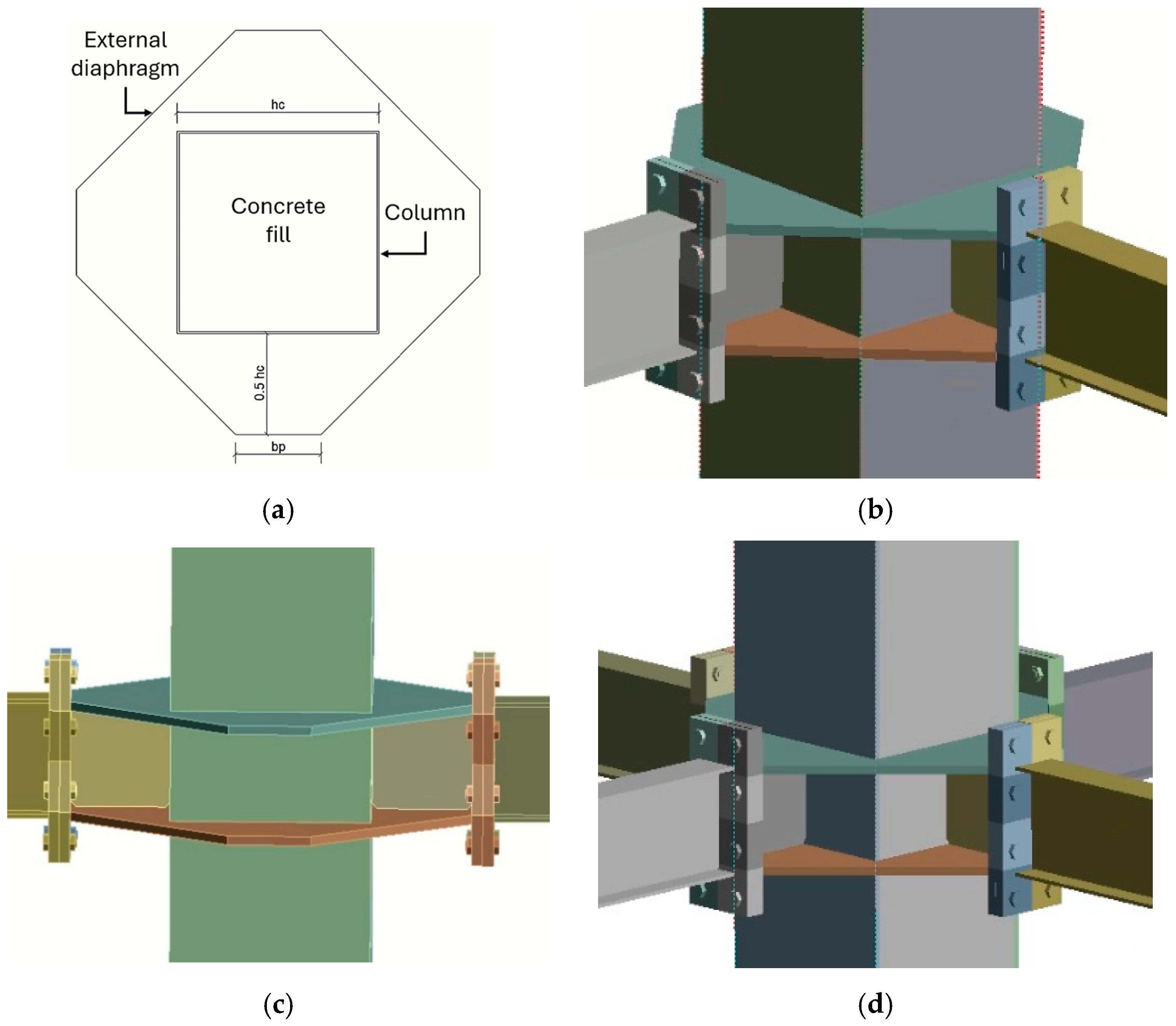
2. Design Considerations of Joint Configurations

In this study, high-ductility slenderness ratios are assumed for beams according to those established in AISC-341 [14]. Thus, the maximum flexural capacity assumed is Mpr = CprRyFyZx (Cpr is the hardening factor according to AISC-341 [14], Ry is the overstrength factor, Fy is the material yield stress, and Zx is the beam plastic modulus). Likewise, the assumed maximum shear is Vu = Vg + 2Mpr/Lh (Vg is the shear due to gravity forces, and Lh is the distance between plastic hinges). Furthermore, to assess the performance of the connection for IMF and SMF use, the span-to-depth ratio was restricted to 12, complying with the lower limit of 7 imposed by Chapter 6.3 in [14]. Moreover, to comply with stability bracing according to [14], lateral bracing was granted to the beams to limit the laterally unbraced length of the beam and reach the yielding given by AISC-360 [48].
Furthermore, CFT built-up columns were designed by varying the width-to-thickness ratio from the high ductility limit, established in Table D.1.1 in [14], to non-compact and slender columns, according to Table B.4.1.a in [48]. Following the moment connection proposed by the authors of [44], the end plates were linked to the column by horizontal stiffeners. Moreover, a length–depth column ratio of 10.32 was considered for all models to simulate a typical story height of a domestic Chilean construction. In addition, the axial load for the column design was equivalent to 0.25 Py, considering Py as the yield axial load (Py = FyAg). Likewise, as a continuation of the research previously conducted by the author, the design of the end plate was executed based on the analytical expression derived from the experimental and numerical research conducted by the authors of [44]. The shear capacity of the column was designed in accordance with the requirements of the Seismic Provisions [14], considering two webs of the CFT column for its verification and the filling concrete strength according to [49].
On the other hand, the external diaphragms were designed to support the maximum factored force on the beam flange (Ffu) considering a yielding failure mechanism, as suggested in [50]. However, a geometrical limitation was added to avoid the joint stress concentration, which led to a column-yielding mechanism. In this sense, the minimum length of the external diaphragm is considered as the half of column width (0.5 hc) and a support length equivalent to the width of the end plate (bp), as shown in Figure 1a with the model configurations of this study (Figure 1b–d).
The strong column–weak beam ratio (SCWB) was computed with the consideration of the moment of attached beams and the axial load of the column, similar to that proposed by the authors of [50]. On this basis, 50% of the flexural strength moment will be in the orthogonal direction to the analysis plane beams (My) according to [14]. The axial load of 0.25 Py was considered as design load because is the typical axial load level of Chilean SMFs. However, the specification of [14] for the estimation of column strength for this verification considers the expected plastic moment of the column as a high-ductility member. In this sense, the proposed design methodology established a new way to compute the maximum available column strength considering the slenderness effect, axial load, and bidirectional effect, modifying the equation specified in [14] to Equation (1).
M p c = M n F y c P A + M y Z y F y c
where Mn is the available column strength estimated according to Chapter H in [48] for composite members. The current standard only considers the use of high-ductility members as columns, whose capacity is only referred to the plastic moment Mp. In a sense, this modification allows to consider the slender effect and the other terms of Equation (1), such as the reduction of strength by the bidirectional effect. Thus, to consider the bidirectional strength effect, the number of connected beams is varied considering three configurations: two beams in the plane (2BI), two beams connected in the corner (2BC), and four beams (4B) in total. The incorporation of this factors allows to obtain designs using elements with a greater width-to-thickness ratio, with the purpose of achieving a smaller amount of steel material in the final design. This goal leads to a reduction of 28% of water footprint according to emission calculations given in [51].
In addition, a variation in the cross-section of the beam is introduced to look for a robust trend in the behavior and evaluate patterns and possible dimensional limits of the connection, such as the connections established in [18]. Finally, the dimensions obtained from these assumptions were used for the other column width-to-thickness ratio examined in this study, with the objective of studying the influence of slenderness in the SCWB ratios considering the modification of the column thickness. An outline of the design results is given in Table 1, considering the column as a slender element and then increasing their thickness to comply with the width-to-thickness ratio of non-compact and high-ductility members. Moreover, in previous research [43] where a high-ductility box column was employed for the same connection configuration, the dimension of the column obtained for an IPE200 beam was 220 × 220 × 14. In this sense, in comparison to the dimension obtained in the current study, a reduction of 41.60% of the steel weight per unit length of the column is obtained.
All previous designs were evaluated for the three connected beam configurations previously mentioned, as well as two different column slenderness conditions for two-beam models and three column slenderness conditions for four-beam models. The purpose of these configurations is to assess the influence of the bidirectional effect and the column slenderness simultaneously, which has not been evaluated in previous studies (e.g., [39,40]). Table 2 summarizes the number of models per configuration evaluated, and a diagram of these configurations is given in Figure 1.
Table 2 shows the simulation matrix with the 70 models considered in the numerical study. In this sense, three types of joint configurations are considered: 2BC, a column with two beams connected as a corner joint; 2BI, a column with two beams connected as an interior joint; and 4BC, a column with four beams connected as an interior joint. The beams 2BC and 2BI were modeled to study the effect of bidirectional load and the shear transfer mechanism to the web panel zone, while the 4BC models were used to compare the cyclic performance at maximum applicable loads and to identify the failure mechanisms of such connections.
In all cases, the beams were connected with bolts through the end plate to the columns. The columns have vertical and horizontal stiffeners that stiffen the node and improve the transfer of the cut from the beams to the column. In all cases, the load was applied at the top end of the column. However, a more detailed description of the numerical models is given in the following sections.

3. Numerical Models

This section describes the numerical modeling of a steel I-beam and CFT column moment connection employing the finite element method (FEM) within the ANSYS software [47] framework. The aim is to simulate the structural behavior, considering the interaction between the beam, column, end plate, and bolts under cyclic load conditions. The numerical model provides a high-fidelity analysis, incorporating detailed considerations such as accurate mesh, realistic boundary conditions, and the application of bolt pretension. This computational approach serves to simulate the laboratory condition in a virtual environment, according to the established in prequalification code [14]. The results obtained from the numerical simulations contribute to the validation of the proposed design equation and offer insights into the structural integrity and reliability of the proposed moment connection. The model includes the material fundamental law, loading conditions, boundary settings, mesh size, and FE type to solve the nonlinear interaction between the elements when a cyclic load in a nonlinear range is analyzed. Nonlinearities are considered using sub-steps for each load stage employing the Incremental Newton–Raphson procedure [47,52].

3.1. Material Fundamental Law

In this research, the material data employed for steel were obtained from the material experimental test performed in [46]. In this sense, the ASTM A36 material is considered for horizontal and vertical stiffeners, end plates, beams, and columns, whereas ASTM-A325 is assumed for the bolts. For the modeling of these materials, the von Mises yield criterion, along with the nonlinear bilinear kinematic fundamental law, was employed; therefore, the yield surface is constant in magnitude. In addition, the properties to be introduced in the model were converted to true strains and true stress to consider the actual change in the length of a material as it deforms. On the other hand, we used concrete material with a compressive strength of 28 MPa and the Microplane model based on the Drucker Prager model calibration as several studies [53,54,55] suggest for confined concrete with 41 MPa as the confined compressive strength, 46 MPa as the biaxial compressive strength, 3.8 MPa as the uniaxial tensile strength, 1 as the damage parameter (Rt), 40,000 MPa/m as the hardening parameter (D), and −35 MPa as the compression cap location as the model parameters. This consideration allows the capture of the brittle failure and fracture mechanism in the concrete. Table 3 shows the material properties of the steel materials employed.

3.2. Loading and Boundary Conditions

In the FEM models, the following considerations were assumed: the length of the column was considered as the distance between the points of zero moment for each case (with the points of zero moment assumed to be at half of the height of the columns). The beam length was determined by the clear span of the beam, denoted as (L). Furthermore, the length of L/2 was used to simulate the distance to the point of zero moment for seismic loads. Welds were excluded from the model because inelastic behavior was not anticipated in these components. The diameters of the holes were assumed to be standard in accordance with the requirements specified in Section J3 in [48]. These assumptions were validated and utilized by the authors of [10,44]. An optimized end plate thickness based on an analytical proposal using yield line theory was derived from previous research [44].
The base connection of the column was modeled as being partially restrained, allowing rotation only in the direction of the load application. The beams were modeled as being simply supported, restricted only in the “Z” direction to simulate the load cell boundary condition. Additionally, lateral bracing was applied to the two beams to ensure their stability in accordance with [14,48]. For all configurations, the loading protocol was applied at the top of the column to ensure similar loading in all beams as suggested in [43]. Nevertheless, to prevent out-of-plane instability, lateral support was provided at the top of the column. Figure 2 illustrates the boundary conditions employed in the four-beam (4B) model configuration. The loading protocol involved applying horizontal displacements at the top of the column following the prequalification protocol outlined in [14], with models 2BC and 4B subjected to a 45° load to induce the bidirectional effect. Furthermore, bolt pretension was applied to 70% of the nominal tensile strength of the bolt shank surface, according to [48].

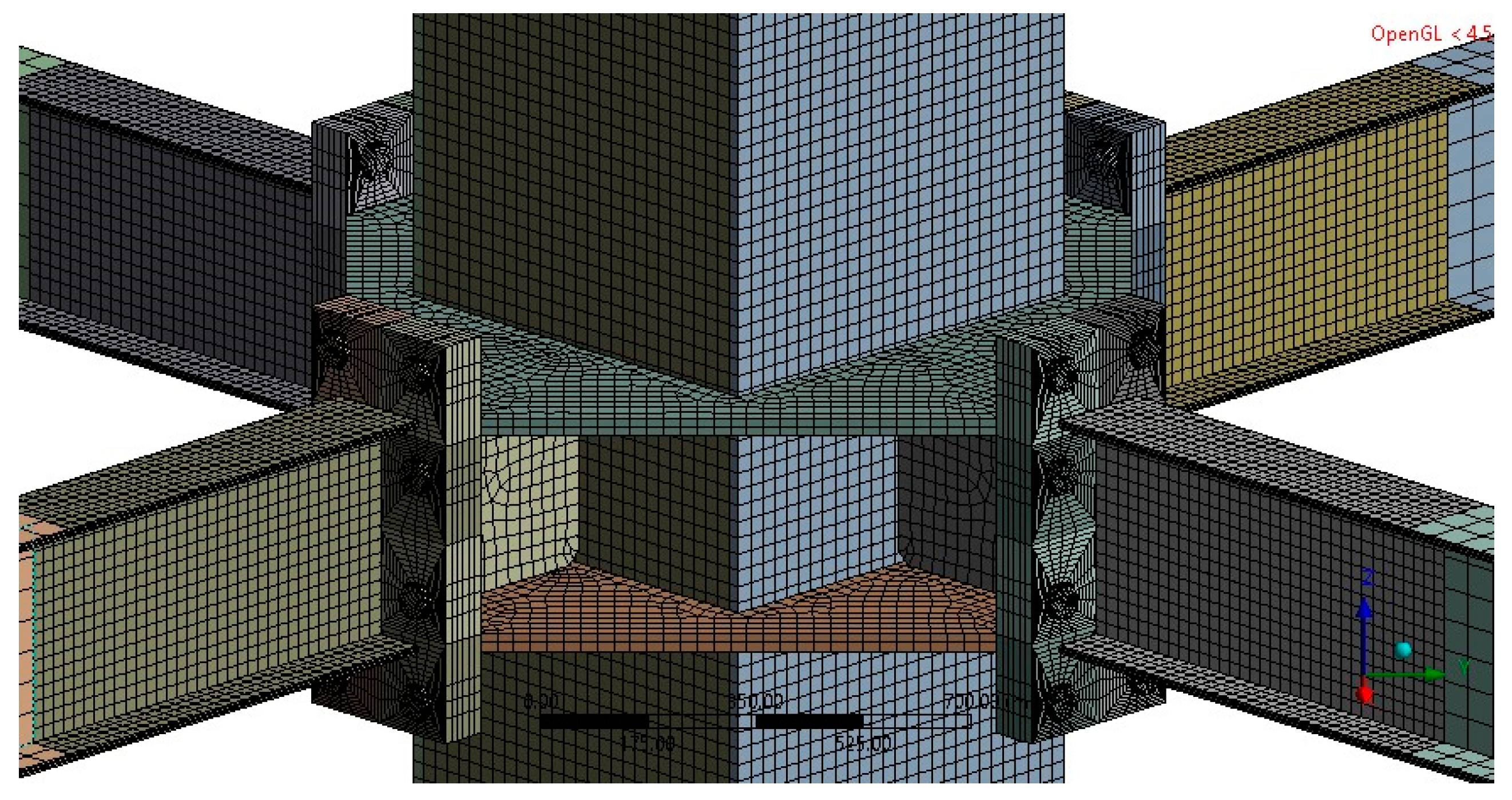
3.3. Finite Element Type, Mesh Size, and Contacts

In this study, SOLID185 was used in steel elements as a prism-shaped body, which has a good competence to creep, plasticity, large deflection, and stress stiffening. On the other hand, the finite element “CPT215” was used to fill concrete due to the incorporation of the “microplane” model, which included elasticity, tension rigidity, large deflection, and deformation capabilities to simulate the gradual failure of concrete. Additionally, this element was used because the mesh sensitivity of the “CONCRETE/SOLID65” element does not allow tracking the cracking behavior of concrete when it fails, without having to track individual cracks, as demonstrated by previous research [56,57]. The “microplane” model with a newer CPT215 element returned force–displacement results that did not have significant mesh sensitivity and agreed very well with the experimental data. In this sense, a simple model calibration for the element type was developed and is shown in Figure 3, based on the previous experimental research of [58] and numerical results of [59], which employed the SOLID65 element. The results indicate that the local buckling effects are possible to represent and that the numerical results of the use of the CPT215 element have a good agreement with previous experimental and numerical data.
Various mesh sizes and shapes were employed to establish a rational mesh that delivers precise results, incurring excessive computational costs. For instance, a fine mesh was used to capture the inelastic behavior in plastic hinge zones. Furthermore, the author conducted a sensitivity analysis to validate the model’s accuracy and its convergence with mesh refinement, varying the mesh element size from 40 mm to 5 mm. Despite these variations, the structural response remained consistent. Consequently, a maximum element size of 8 mm was chosen for areas with expected nonlinear behavior and 25 mm for areas with linear behavior, based on the conducted tests. Figure 4 illustrates a schematic view of the mesh employed for a four-beam model.
Moreover, to evidence possible p-δ effects and to evade the sub-estimation of the cyclic performance r of the connection during the inelastic deformation, geometrical imperfections were considered longitudinally and transversally in the model [60]. These longitudinal and transversal imperfections were considered according to the maximum limits established in [61,62], which define the imperfections that can appear due to eccentricity boundaries, erection processes, or lack of precision during erection or fabrication. Therefore, in this research, these imperfections were considered using a previous nonlinear case to deform the elements up to the tolerance limits previously mentioned and then running the cyclic load from the previous deformed shape using the “UPGEOM” command. This command updates the geometry of the finite element model according to the displacement results of the previous analysis and creates a revised geometry at the deformed configuration. Thus, when UPGEOM is employed, the current finite element model is overwritten by finite element information from the results file.
On the other hand, in this research, a critical aspect of the numerical modeling process involves replicating welding conditions within the computational framework. To achieve this, a “Bonded” contact, also referred to as a completely restrained contact, was employed. This contact type mimics the welded joints, ensuring that the meshed elements are seamlessly connected to simulate the structural continuity anticipated in a welded moment connection for concrete-filled tubular (CFT) members. In addition, by utilizing the “Bonded” contact, the model accounts for the rigid connection established during the welding process. Likewise, the interplay between different elements within the numerical model was addressed by implementing a “frictional” contact mechanism. This contact type allows for the simulation of potential relative displacements between connected elements, a crucial consideration in the cyclic behavior of moment connection. In particular, a friction coefficient of 0.3 was applied to represent the friction zones between steel elements as end plates, bolts, or nuts, while a coefficient of 0.6 was assigned to concrete–steel interfaces. These values were chosen based on prior research findings (references [10,24]), ensuring a realistic portrayal of material interactions. Therefore, incorporating these coefficients, the simulation not only captures the theoretical aspects of CFT moment connections but also draws on practical insights derived from prior experimental studies. Furthermore, Table 4 shows the summary of the contacts employed in the model.

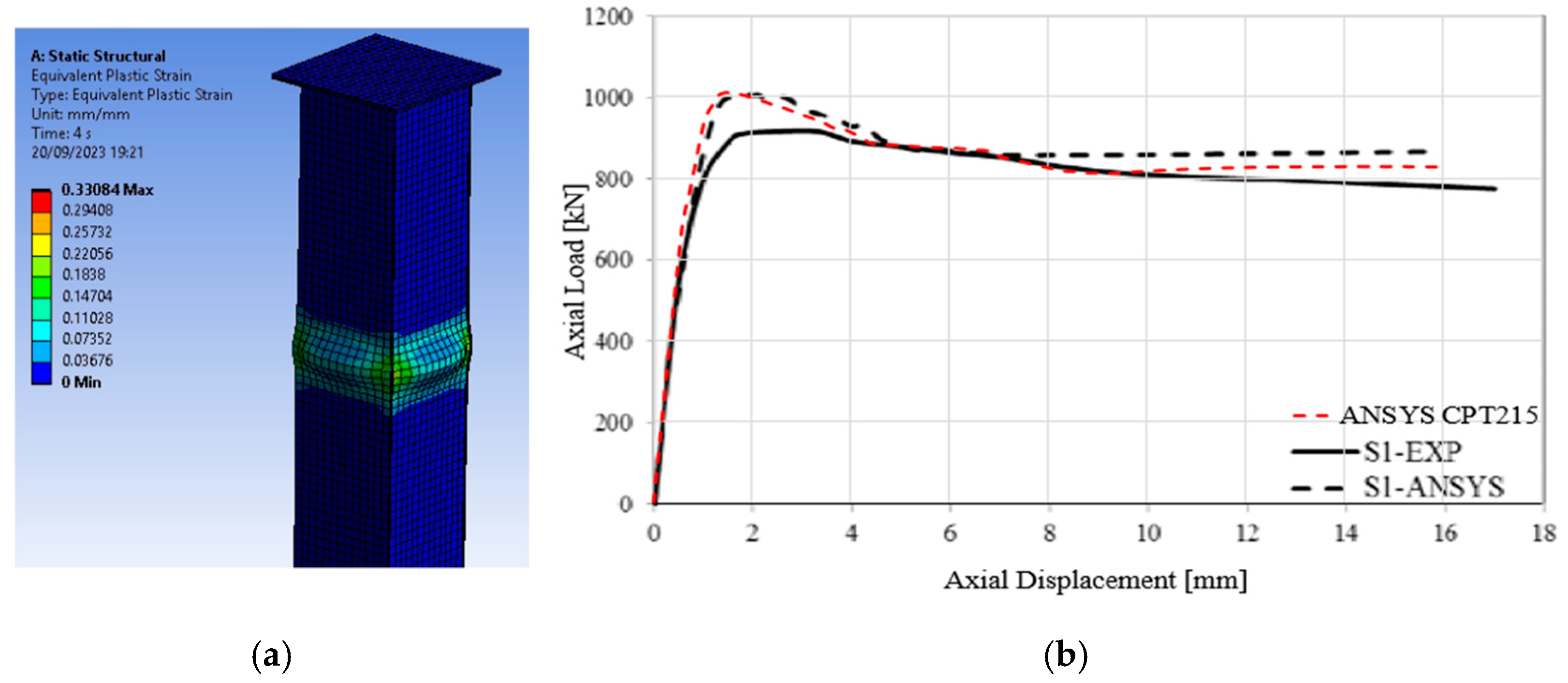
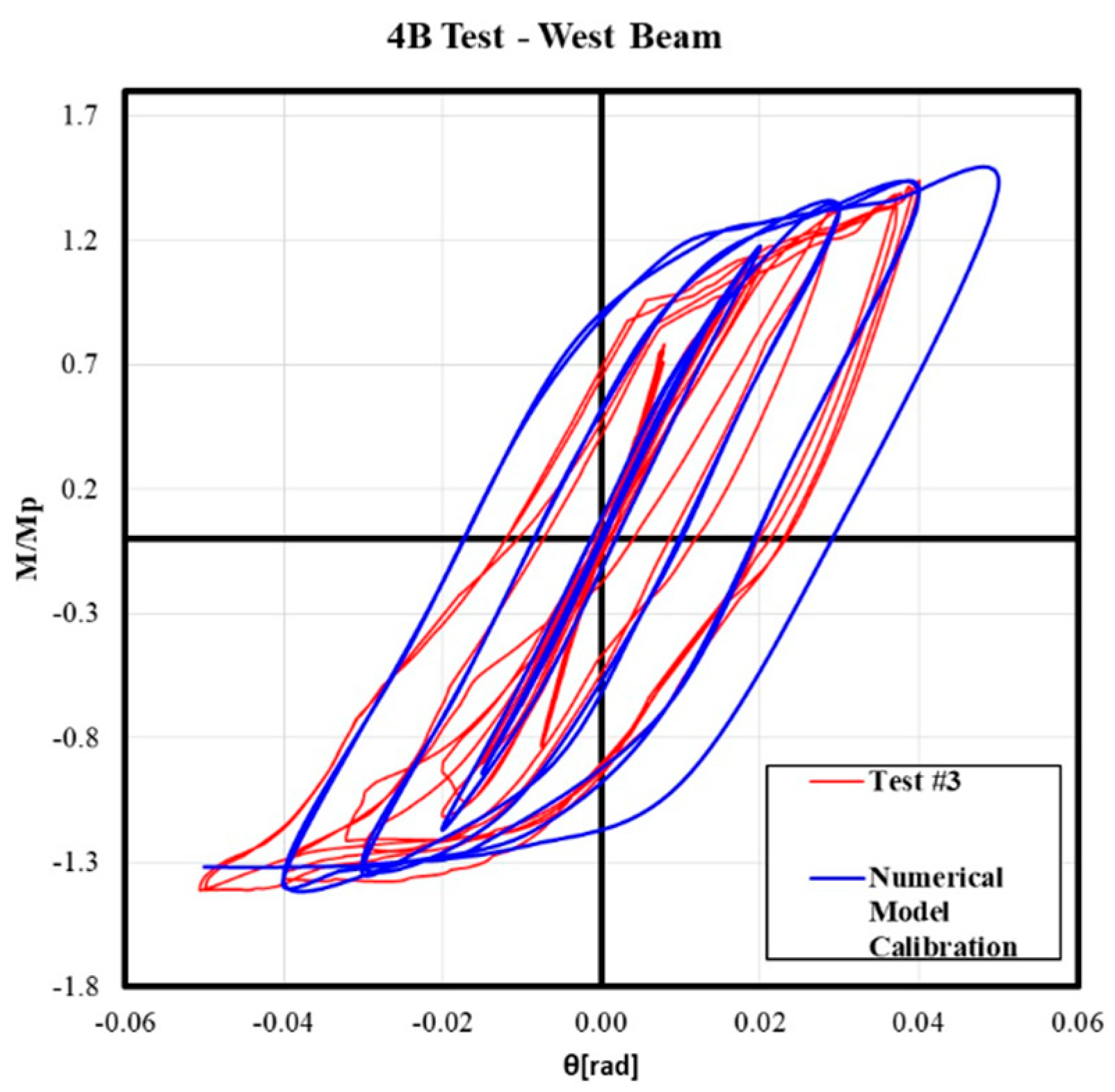
4. Calibration and Validation of the Numerical Model

Some studies, such as [63,64], included parametric analyses and the examination of different connection configurations through experimental tests, not necessarily from the same research. Numerical models were calibrated based on these tests to accurately replicate the studied physical phenomena. For instance, the authors of [65] performed a numerical study on circular tubular connections, calibrated from a specimen tested in [66], while the authors of [67] analyzed baseplates with chairs using FE numerical models calibrated from a test with ductile bolts developed in [68]. In this sense, it is possible to calibrate numerical models from different experimental test configurations, with the failure mechanism and physical phenomenon that control the model and the test being similar. Consequently, in this study, a previous numerical model was adjusted using experimental data from [46], which used the same connection configuration as that proposed in the present study but using a built-up column without concrete-filled. The results of the calibration, showing an acceptable match between the models’ normalized hysteresis curve and the experimental specimens, are illustrated in Figure 5.
Moreover, two additional four-beam (4B) numerical models were developed, considering a plastic model of column like steel column without concrete filled and steel column with concrete filled, denoted as adt-01 and adt-02, respectively. The purpose of these models is to ensure that the calibrated model can reproduce the local buckling and failure mechanism when the connection is not designed with the proposed methodology. In this case, only the 4B model was used because it is the most severe condition for the node. Figure 6 shows the plastic strain distribution for the models adt-01 (Figure 6a) and adt-02 (Figure 6b), and the high-ductility and slender models, designed according to Section 2, are shown in Figure 6c,d, respectively. These results illustrate how the local buckling effects are strongly denoted in the additional models, even in the presence of concrete filling. Furthermore, the failure mechanism manifested in the additional models were local buckling and plastic hinges in the column for filled and non-filled concrete models, respectively. The results obtained validated that the numerical model is capable of reproducing fragile failure mechanisms. On the other hand, the other models designed using a high-ductility column or a slender column with the proposed design methodology exhibit a failure mechanism characterized by plastic hinges in beams, as is desired for connections for SMFs. In addition, no brittle failure or column damage was evident in these configurations.

5. Results of the Parametric Assessment of Cyclic Behavior

The research aims to propose a moment connection with a similar configuration as that in [44], incorporating a CFT slender column for multiple beams. Considering this objective, the results of the bidirectional effect are evaluated from models 2BC and 2BI because they have a similar number of connected beams. In addition, these same models are compared for non-compact and slender columns in terms of moment rotation, secant stiffness, and dissipated energy. To further gauge the effect of the slenderness of the column, the following section shows the results of 4B models for slender, non-compact, and high-ductility CFT columns in terms of moment rotation, secant stiffness, and dissipated energy, supplemented by equivalent stress and plastic strain distribution. Additionally, the assessment of the concrete core damage section shows the equivalent plastic strain and normal stress of the concrete core, while the rupture index assessment section presents this parameter for different configurations concerning slender columns and connected beams. Notably, for all cases, the slender and non-compact columns were designed with a new methodology that avoids brittle failure mechanisms and predominantly showcases plastic strain concentration in the beams.

5.1. Bidirectional Effect

Comparing the performance of the bidirectional effect models 2BC and 2BI for non-compact and slender columns in terms of moment rotation, secant stiffness, and dissipated energy reveals differences in their behavior under cyclic loading. This comparison aims to elucidate how these bidirectional effect models react to cyclic loading, shedding light on their practicality and reliability in structural analysis. Figure 7 and Figure A1 show this comparison in terms of cyclic response, where it is observed that as the beam section increases, the effect of the pinching on the hysteretic curve is evident. Furthermore, for all cases, the maximum resistance of the connection (Mp) is reached and is never lower than the prequalification limits proposed by the authors of [14], i.e., 0.8 Mp at a drift of 0.04 rad, which was reached by all the models. On the other hand, the models that consider the bidirectional effect (2BC) present a reduction in their stiffness compared to the other models (2BI), which have lower resistance. Nevertheless, a greater pinching is denoted in the response of 2BI models, which allows us to infer that the bidirectional effect provides stability to the system. The reduction in strength and stiffness obtained in the 2BC joint models compared to the 2BI joint models is due to the lower resistance reached by the rhombus-shaped column when two beams are connected in the corner joint configuration. In this sense, the shear transfer mechanism in the web panel of the 2BI joint (interior joints) configuration causes the two walls of the web panel to be aligned with the direction of the load; therefore, there is greater effectiveness in resisting the applied cyclic load. Finally, an insignificant difference in the hysteretic behavior is observed comparing the models for slender and non-compact columns. However, for all cases, less throttling and loss of resistance capacity is evidenced for non-compact models.
Moreover, the secant stiffness is a measure of the strength of the connection to deformation at a specific point along its loading history. The stiffness itself is a measure of how much force is required to produce a unit of displacement; this parameter helps to identify the extent of stiffness degradation in the connection as it undergoes cyclic loading. A decreasing secant stiffness over cycles indicates that the connection experiences damage and yielding. In this sense, Figure 8 and Figure A2 illustrate the normalized secant stiffness degradation of the previously analyzed models. This analysis of the secant stiffness allows for more quantitative evidence of the loss of stiffness shown in the hysteresis curves. The results show that the secant stiffness degrades more than its elastic value (0.01 rad) as the beam section increases. On the other hand, for most of the simulated models, greater degradation was evident for the 2BI models than for the 2BC models where the bidirectional effect is present. This is because the degradation of connection resistance was greater in the models with a bidirectional effect. On the other hand, this effect was evident in both slender and non-compact models, with a difference of approximately 5%. However, this gap between slender and non-compact models decreases as the beam section increases, with the behavior being practically the same. In addition, the variation in the secant stiffness allows us to identify a critical point (2% interstory drift ratio) of the cyclic response, from which, the resistance degradation is initiated for all the models studied. However, this phenomenon is more pronounced as the beam increases in size.
Finally, the accumulated dissipated energy of the system was calculated, considering all sources of inelasticity. This energy was determined by calculating the area enclosed in each cycle of the force–displacement curve of the system using the equation proposed in [69]. The results of the analysis shown in Figure 9 and Figure A3 indicate that the bidirectional effect reduces the system’s dissipated energy by up to 41% of the original value, similar to the findings demonstrated in previous research [63]. Additionally, models with non-compact columns exhibited a smaller reduction in dissipated energy, although in most cases, the difference with slender models was less than 2%. It could be considered that the bidirectional effect increases with slenderness. However, for models exceeding IPE400, an increase in dissipated energy is evident in slender 2BI models due to the concentration of stresses and deformations in the panel zone.
Finally, the cyclic behavior of the connection in comparison to other proposals [70,71] is similar in terms of moment rotation and expected failure mechanisms when the bidirectional effect is not considered. However, for the opposite case, with a bidirectional effect, the performance of other models [41,46] with high-ductility columns is only slightly higher in terms of strength and stiffness. Therefore, this similarity obtained in the behavior between the models in the present study and the other proposals also allowed us to validate that the numerical model can adequately reproduce the physical phenomenon for which it was calibrated.

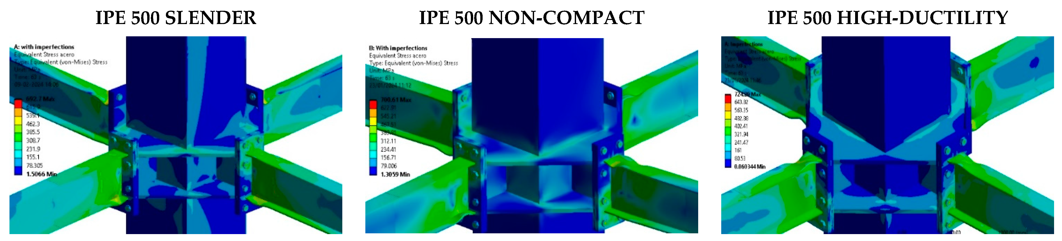
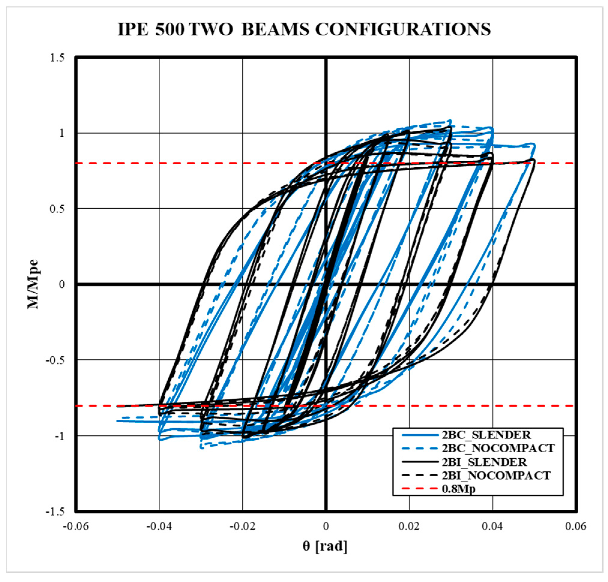
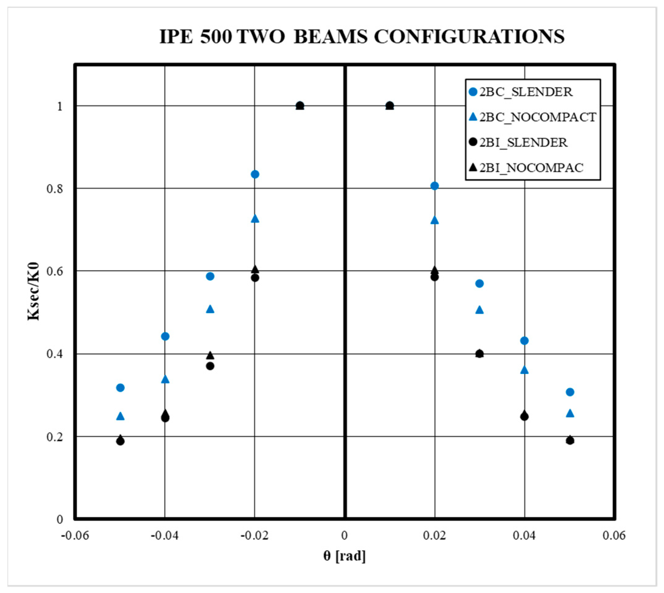
5.2. Effect of the Slenderness of the CFT Column

Analyzing 4B models, this study investigates the influence of column slenderness on slender, non-compact, and highly ductile CFT column. The results are presented in terms of moment rotation, dissipated energy, and equivalent stress/plastic strain. This examination aims to reveal the implications of column slenderness on the functionality and efficacy of moment connection systems, contributing to a better understanding of its effects within CFT moment connection configurations and enhancing seismic design codes and guidelines. In this sense, a comparison of slender, non-compact, and highly ductile CFT columns is presented in Figure 10 and Figure A4 in terms of moment rotation curves of the connection. The results reveal that for all configurations, the prequalification requirements are reached for all models, although the configurations are subjected to four-beam forces simultaneously. The effect of slenderness was not predominant in terms of the hysteretic behavior of the connection; for the first models of smaller beams, the models with slender and non-compact CFT columns presented a very similar behavior. On the other hand, models with high-ductility CFT columns showed greater strength and stiffness compared to models without this width-to-thickness ratio. However, for larger beams over IPE270, the behavior was similar for the three width-to-thickness ratios, which indicates that for the present connection configuration, there is no variation in cyclic behavior because of slenderness. Furthermore, a small loss of resistance and throttling was evident for cycles greater than 0.03rad of drift. Nevertheless, despite this reduction, the connection reached its maximum resistance (Mp) for all load cycles.
For the failure mechanism characterization, the equivalent plastic strains are shown in Figure 11 and Figure A5. For all models, the failure mechanism was given from the yielding in bending at beams, which is expected for special moment frames. Moreover, plastic strains were not evidenced in the column or the panel zone, avoiding the brittle failure mechanism for all cases. The plastic strains were mainly concentrated in the flanges of the beams, starting near the area where the end plate joins the beam and extending along the flange and, finally, towards the area of the web in yielding in shear. Nevertheless, for models with greater beams, up to IPE270, the inelastic incursion was not uniform in the web zone, which can be an indication of a possible local buckling instead of yielding in shear. On the other hand, models with CFT slender and non-compact columns developed lower levels of plastic strain in beams than the high-ductility models because the greater stiffness of the columns limits deformation in the column area, limiting further deformation in the beams.
In addition, the evolution of plastic deformation through loading cycles showed that inelastic incursion begins after approximately 0.015 rad of drift for beams lower than IPE300. However, for larger beams, the plastic deformations begin around 0.02 rad of drift, mainly concentrated in the contact area between the beam and the end plate. Furthermore, this concentration manifests itself in the upper or lower flange of the beam in an asymmetric manner, evidencing greater plastic deformations and local buckling effects in the flange. Conversely, although plastic deformation offers a perspective on the failure mechanism and energy dissipation of the connection, there may be a stress concentration in certain areas of connection. Therefore, that stress concentration can lead to a modification of the dissipation mechanism under higher loading cycles. In this sense, Figure 12 and Figure A6 show a comparison between equivalent stress distributions to analyze if the slenderness effect could modify the failure mechanism and other possible sources of inelasticity in the connection.
For all cases, a joint stress concentration is shown in the node zone as well as in the flange of beams. This stress concentration in the node zone naturally decreases as the slenderness decreases. In addition, for slender models, the stress concentration along the column denotes that the axial load has a major impact in comparison to the other model where the beam action predominates. Likewise, while the external and vertical stiffeners contribute to avoiding damage in the node zone, stress concentration at the union of the external stiffener with the corners of the column is evidenced. Thus, this suggests that damage in this area could be evident in slender CFT columns. In addition, for all cases, a stress distribution in the external stiffener denotes that it is subjected to flexure. Eventually, plastic deformations could be evidenced in this stiffener, in conjunction with a reduction in the stiffness of the connection.
The seismic capacity assessment of moment connections plays a crucial part in the design and analysis of structures, particularly with CFT columns. In this context, one of the aspects for understanding and improving the behavior of the moment connection is the dissipated energy because provides a measure of the capacity of the connection to resist and absorb seismic energy. Moreover, the dissipated energy of the connections contributes to the mitigation of structural damage and ensures the safety of the structures. In this research, the assessment of the dissipated energy is developed through the integration of system forces over applied displacements according to [69], considering plastic strains and tensions reached during the application of cyclic loads. Figure 13 shows the comparison between the dissipated energy computed for four-beam models (4B), emphasizing that for all cases, the high-ductility models dissipate more energy. Nevertheless, models with slender and non-compact columns have similar dissipated energy, which is slightly greater in non-compact in comparison to slender columns. Furthermore, the difference between high-ductility and other slender and non-compact columns increases with the size of the beam because as the beam increases, the stresses in the external stiffener increase, which contributes to energy dissipation from the connection.
According to the moment obtained for all 4B models, a normal distribution was considered for the slenderness data. The normal distribution is a common choice to model continuous data when it is possible to assume a mean value and a standard deviation, applicable to many scientific and engineering contexts. In addition, Monte Carlo sampling was used to simulate the propagation of uncertainty in the data because it is a useful method when the relationship between variables is not known analytically or when the variables are subject to uncertainty. This approach is based on generating random samples of the input variables (in this case, the moment) and evaluating the objective function (the relationship between slenderness and moment) for each sample. A total of 10,000 samples were obtained for each slenderness value and are shown, in Figure 14, with the 5th and 95th percentiles to establish a confidence interval of the values obtained. The results obtained support the findings of the rotation moment behavior, demonstrating that even for other slenderness values not analyzed in the present study, the moment is always higher than the minimum value proposed in [14].

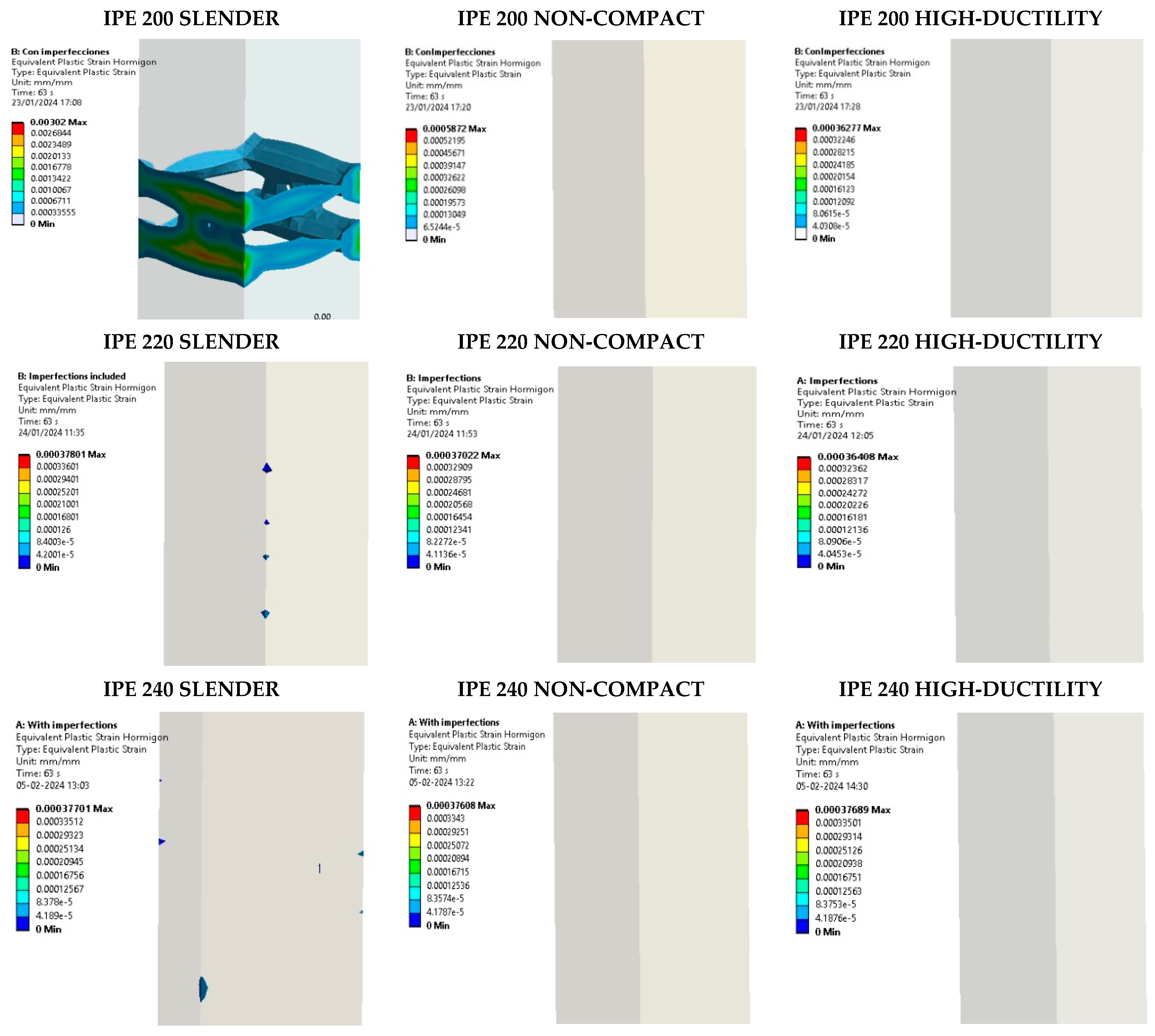
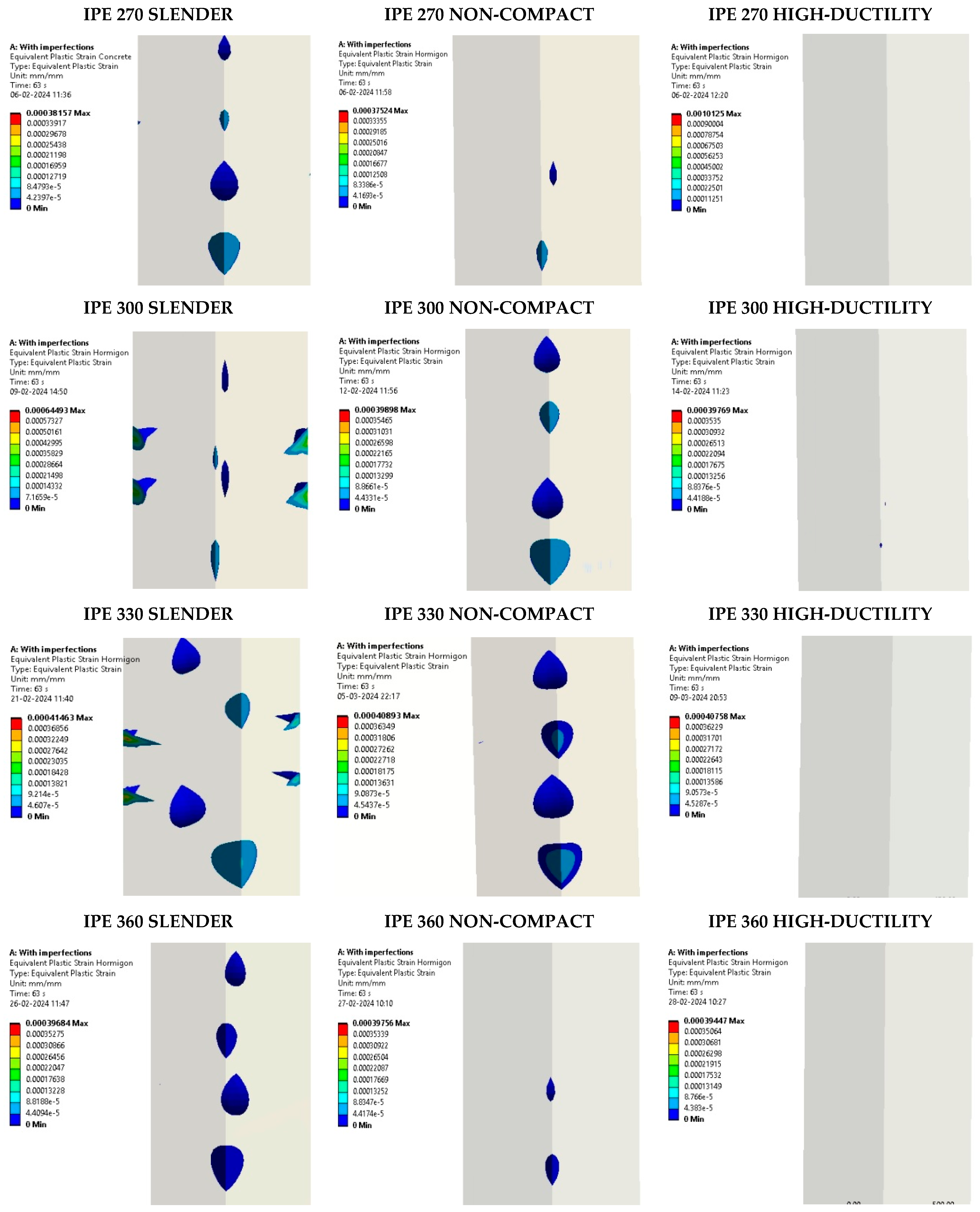
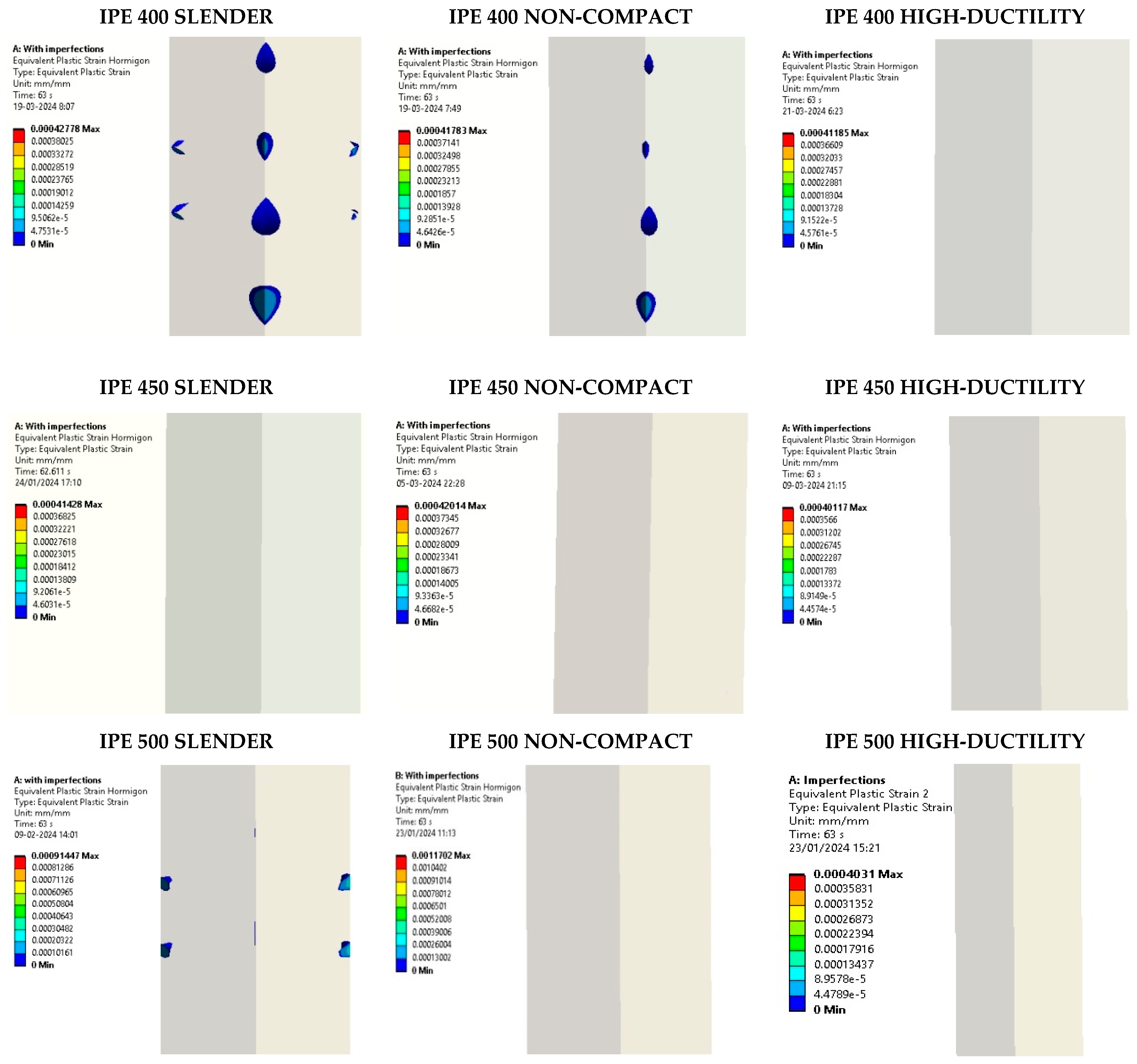
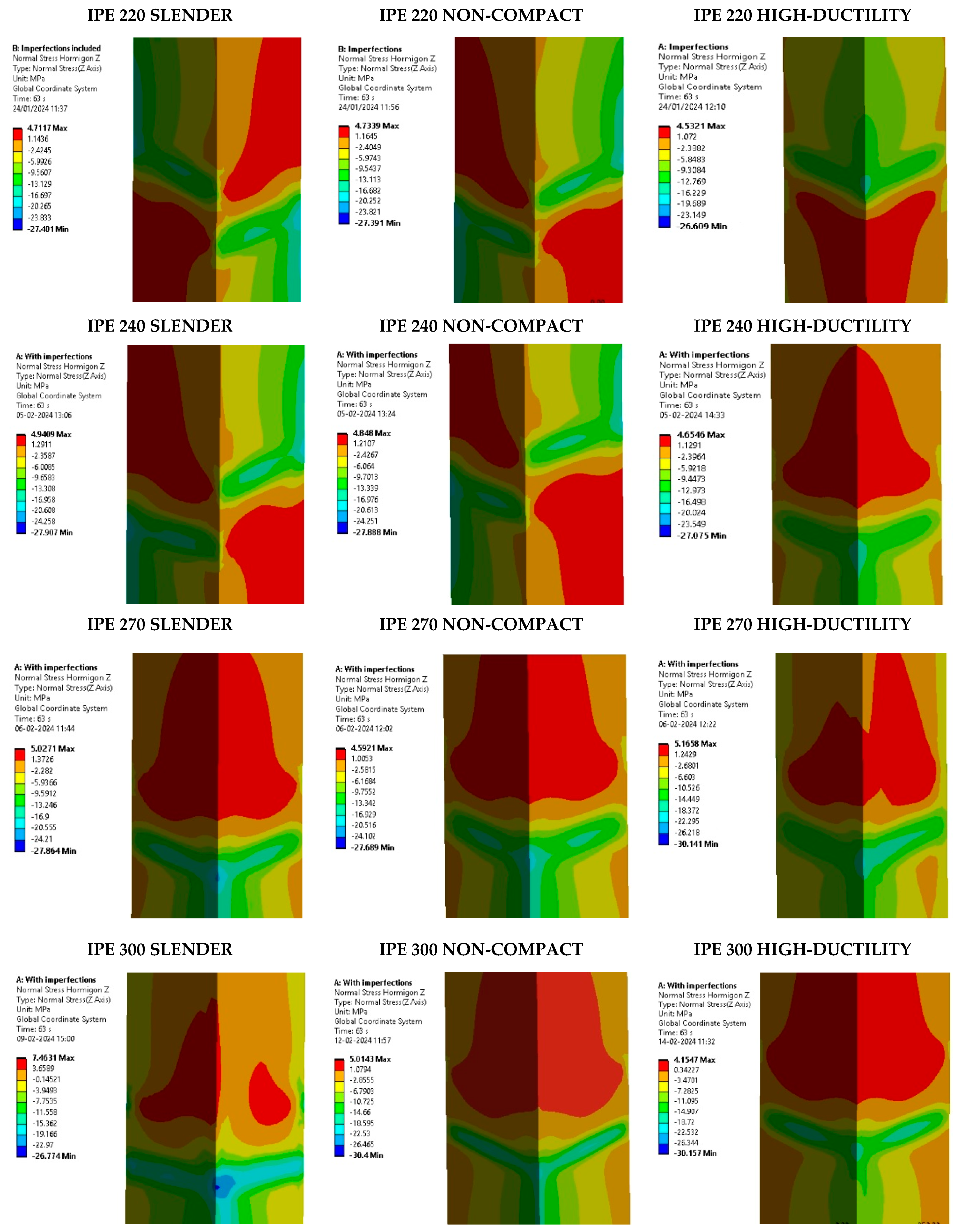
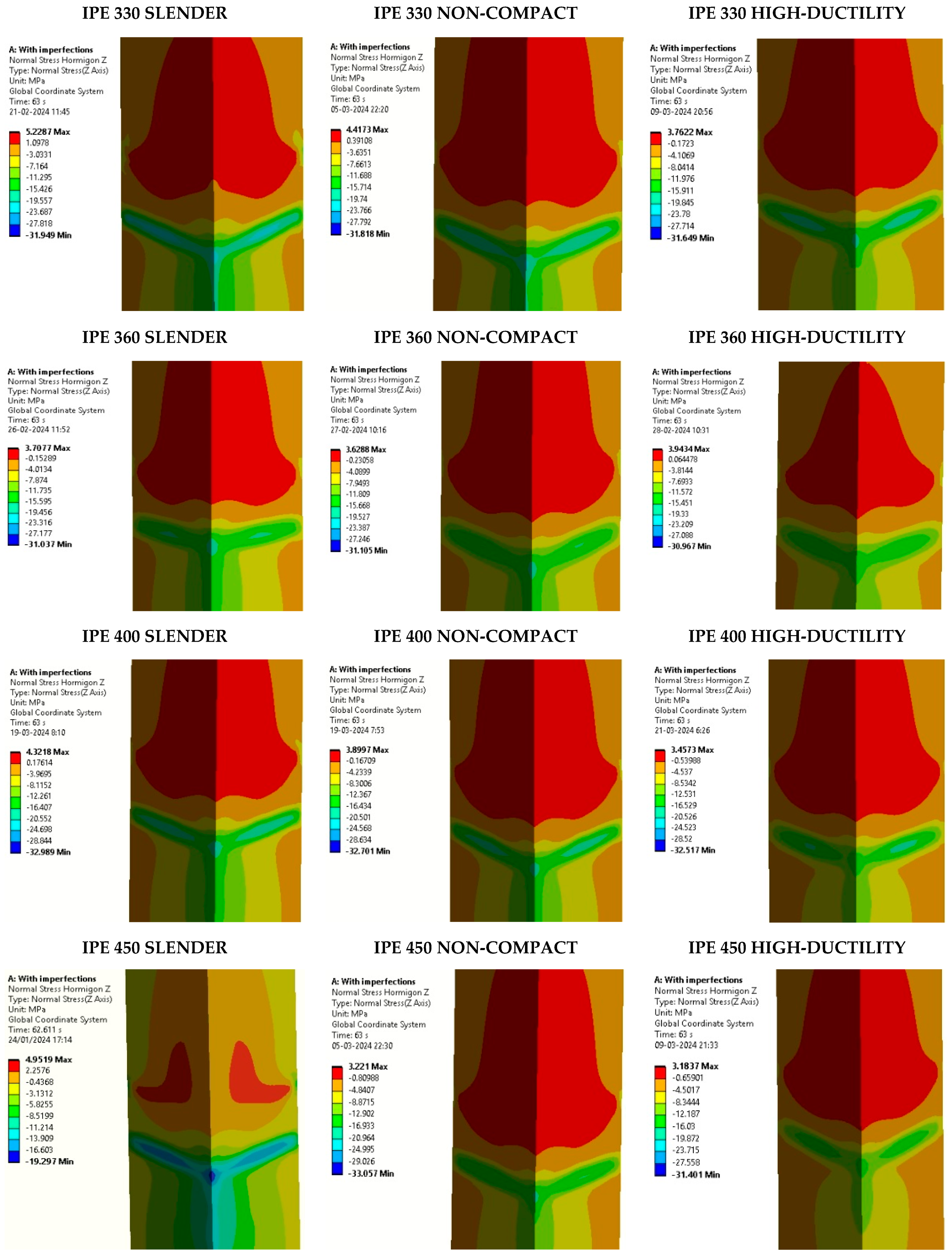
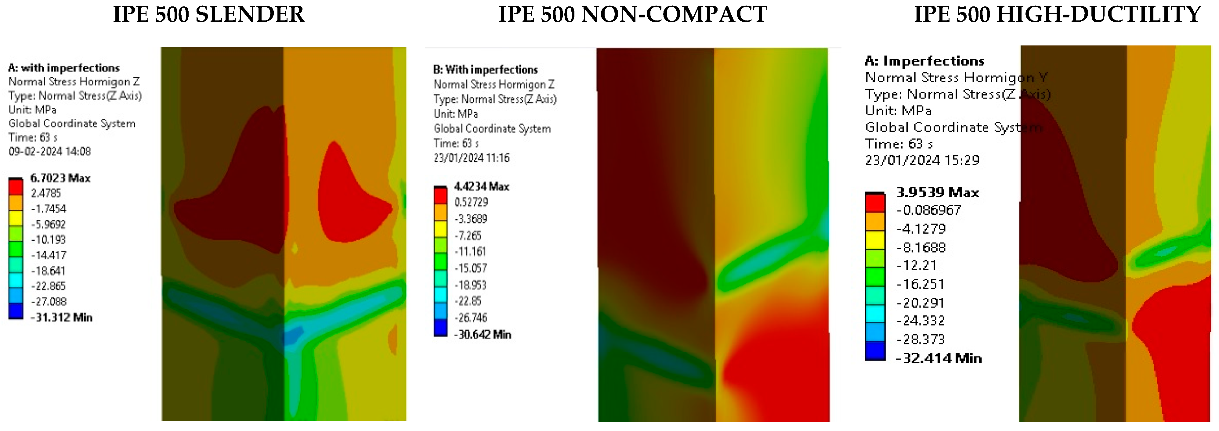
5.3. Assessment of Concrete Core Damage

The evaluation of concrete core damage is pertinent to evaluate the reliability of concrete after being subjected to cyclic loading. Additionally, identifying and assessing concrete damage allows precautionary measures to be considered to repair or retrofit connections after an earthquake. In this sense, the plastic deformations in the concrete core are compared, as shown in Figure 15 and Figure A7, denoting that there is no damage for high-ductility models, as expected. Moreover, most of the other models exhibit plastic deformation, which is an indication of damage to the concrete. However, as the width-to-thickness ratio is reduced, the plastic deformations in the concrete core decrease, showing that for non-compact sections, there could be damage, but to a lesser extent than a slender section. Conversely, plastic strain concentrations occur near the column’s corner, with most of them appearing after a drift of 0.045 rad. Nonetheless, the IPE200SLENDER model shows that plastic strain is concentrated in the external stiffener–flange beam zone, which does not occur in the other models. Furthermore, although the distribution of plastic deformations does not follow a clear trend in its behavior, the damage to the concrete core is concentrated in slender models due to the action of the external stiffener under the column.
Based on the findings of this study, the concrete damage is also dependent on plastic deformation because when the concrete reaches its tensile strength. In this context, the analysis of the normal stresses in the concrete core is shown in Figure 16 and Figure A8 as a comparison between the different slenderness values analyzed. These values are compared to the ultimate compression strength (fc) of 41 MPa and the ultimate tension strength of 3.8 MPa, estimated according to [49], considering confined concrete. The results indicate that for most scenarios, even in high-ductility models, the tensile strength is exceeded, which means the concrete is cracked. Nevertheless, the stress distribution shows that the concrete is cracked beyond the node zone of external stiffeners, mainly in the corners of the column. On the other hand, the maximum compression stress is evident in the zone of the beam flange subjected to compression by the action of the moment. This shows that the effect of the external stiffener allows these stresses to be dissipated in the node area compared to a scenario where the beams are directly connected to the face of the column.
On the other hand, the damage in 2BC models was greater than in 2BI models, independent of the slenderness ratio. Plastic strain was shown in most of the 2BC models around the external stiffeners and beam flange zone, in contrast to 2BI models where they were concentrated only in the beam flange zone and column corners. Moreover, the normal stress distribution of 2BC models shows a major area of the concrete core, which surpasses the rupture modulus and is cracked on the face of the column where the beam is connected. Likewise, based on a similar analysis, the normal stress distribution of 2BI denotes a cracked area on the panel zone without surpassing the normal compression strength in the other zones with compression stresses.

5.4. Rupture Index Assessment

The rupture index provides a measure of the vulnerability of the connection subjected to cyclic loads. In addition, this allows us to identify the critical zones of the connection that have a high potential for rupture and could be weak points in the overall structural design. The identification of these points makes it possible to take preventive action to reinforce or modify the connection as necessary. In this research, given that the explicit fracture has not been simulated, the rupture index is assessed to obtain an additional validation of the results obtained in the previous analysis. This helps to strengthen confidence in the study findings and support the results presented. Thus, the rupture index is computed according to Equation (2) for a drift level of 0.03 rad, as previous studies suggest [72].
R I = P E E Q / ε f e x p ( 1.5 p q )
where the PEEQ is the equivalent plastic strain, ε f is the ductile fracture strain, and p and q are equal to the hydrostatic pressure and von Mises stress, respectively. The choice of this level of damage is because damage to the structures begins to occur when rotations are greater than 0.02 rad. Furthermore, according to the Seismic Provisions, it is not expected that there will be repairable damage for rotation levels greater than 0.03 rad. Figure 17 shows the typical rupture index distribution greater than 1 obtained for 2BC, 2BI, and 4B models in the case of beam IPE450 and a slender column, denoting how the rupture index is mainly concentrated in the beams and flanges. However, for 2BI models, there is a similar distribution along the plastic hinge of the beam, with a punctual rupture concentration in the flange of the beam, which is an indication of a large plastic deformation in that zone. In this sense, higher values of the rupture index are due to the large plastic strains that are developed in the flange of the beams, denoting that as the number of beams increases, the rupture index also increases. Furthermore, the stress distribution shows a minimum value of the rupture index in the corners of the column as a product of the stress concentration of this zone. Nevertheless, in general, the results show that the connection behavior is essentially ductile.
On the other hand, although the rupture index distribution and values were similar for all models analyzed, a comparison of the average rupture index values at the flange of the beam for 0.03 rad is shown in Figure 18. This analysis aims to evaluate the impact of the slenderness effect and the moment connection configuration on the connection damage and rupture index. The results show that as the slenderness decreases, the rupture index increases due to the large plastic deformations in the beam by avoiding the deformation of the columns. In addition, the comparison between 2BC and 4B models shows that as the number of beams increases, the rupture index also increases. However, an increase around the double rupture index is evidenced in 2BI models as a product of stress concentration generated in the flange of beams by local buckling. Therefore, these results denote that although slender models present some pinching in comparison to non-compact or high-ductility models, they are less susceptible to fracture phenomena. Moreover, these findings suggest that the fracture potential of the connection reaches the limit of rupture after the material develops its ductility.
In Table 5, a summary of the key parameters of the studied models is shown.

6. Conclusions

In this paper, the influence of the column slenderness ratio on the behavior of the bidirectional moment connection between the I-beam and CFT column was studied numerically through a parametric study. In addition, new considerations in the design of bidirectional moment connection with slender columns are proposed and implemented in the design of the models evaluated in this study. A total of 70 high-fidelity FEM models are developed using ANSYS software calibrated from experimental studies. Furthermore, different width-to-thickness ratios, such as slender, non-compact, and high-ductility ratios, were considered in column members. The main conclusions are described as follows:
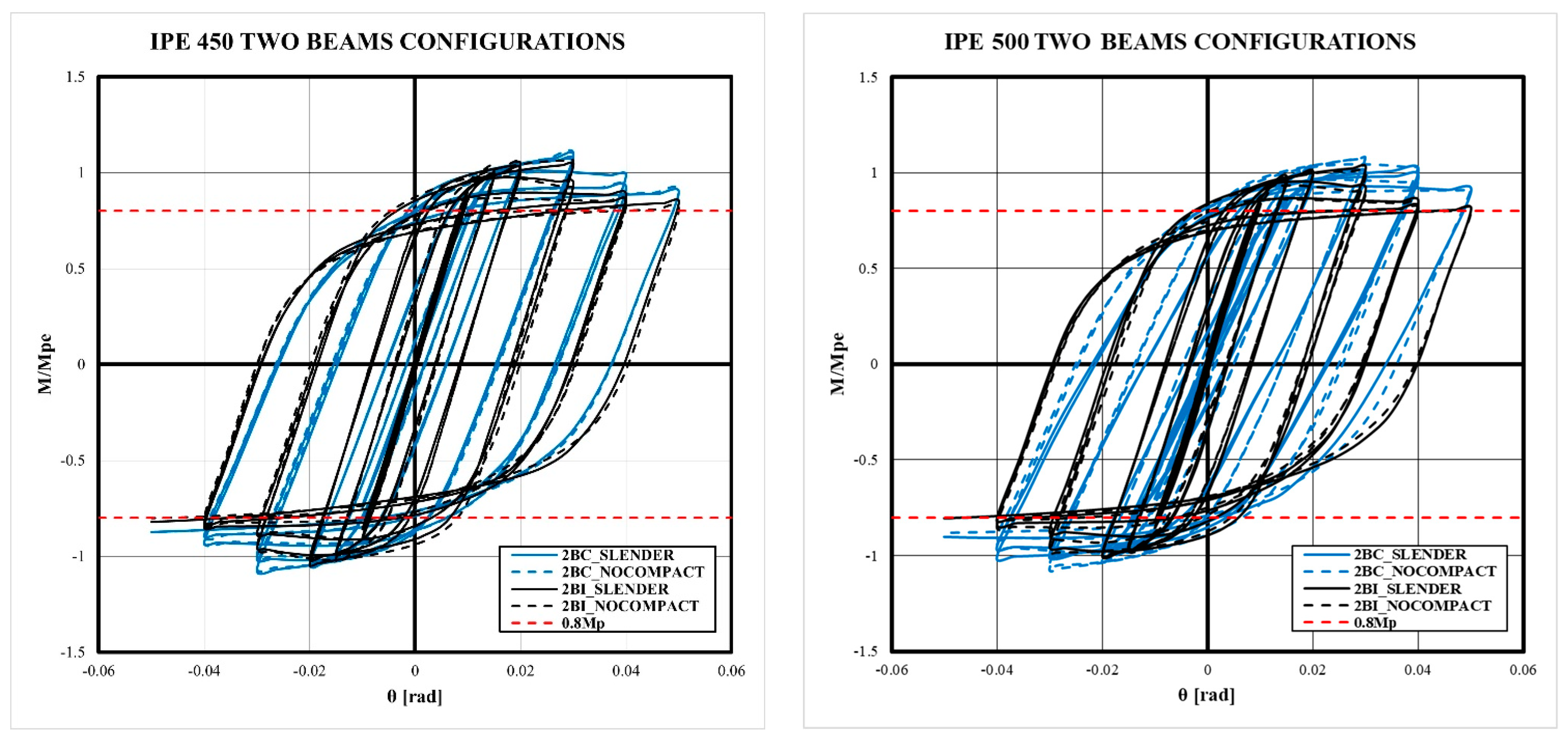
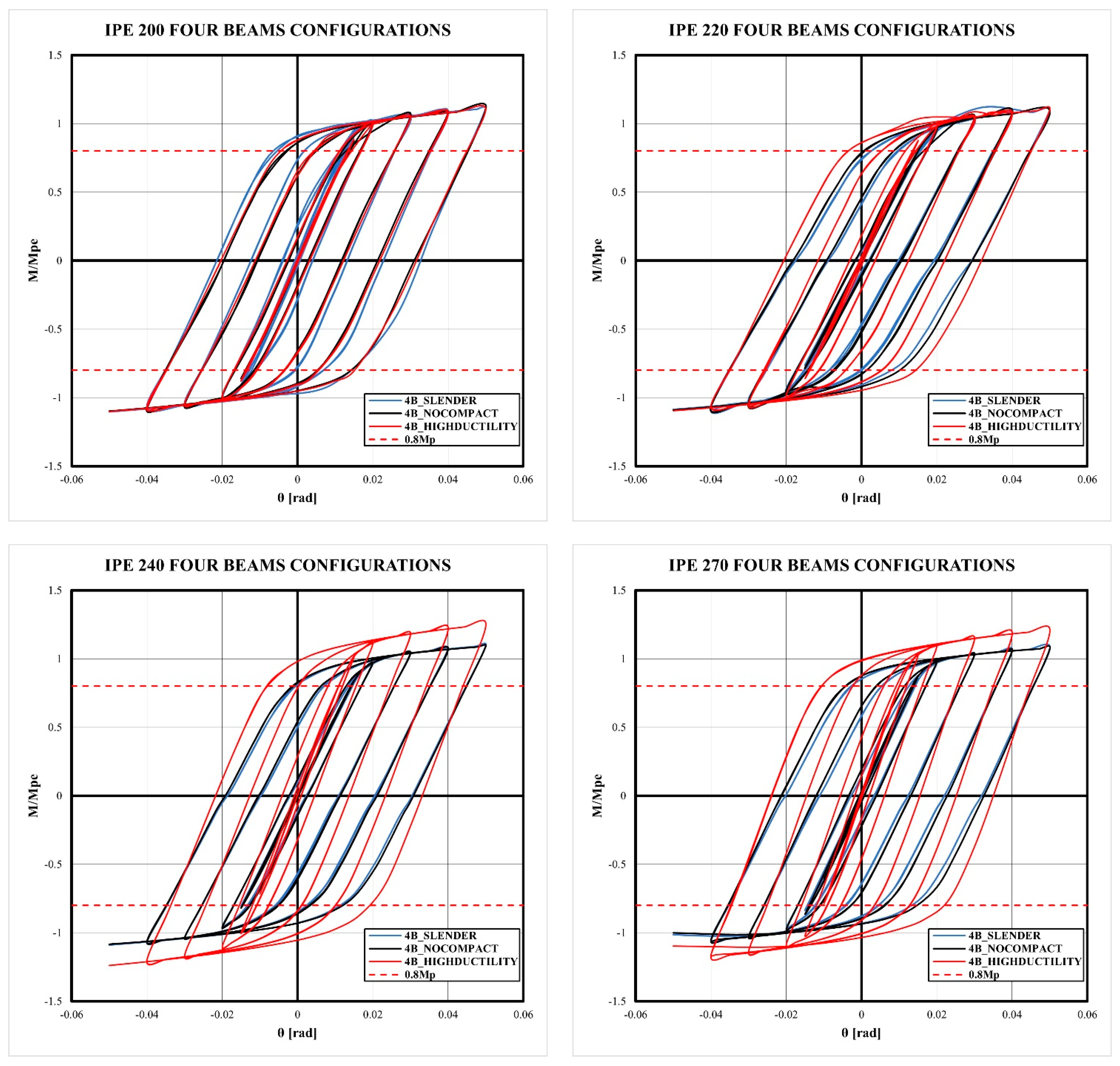
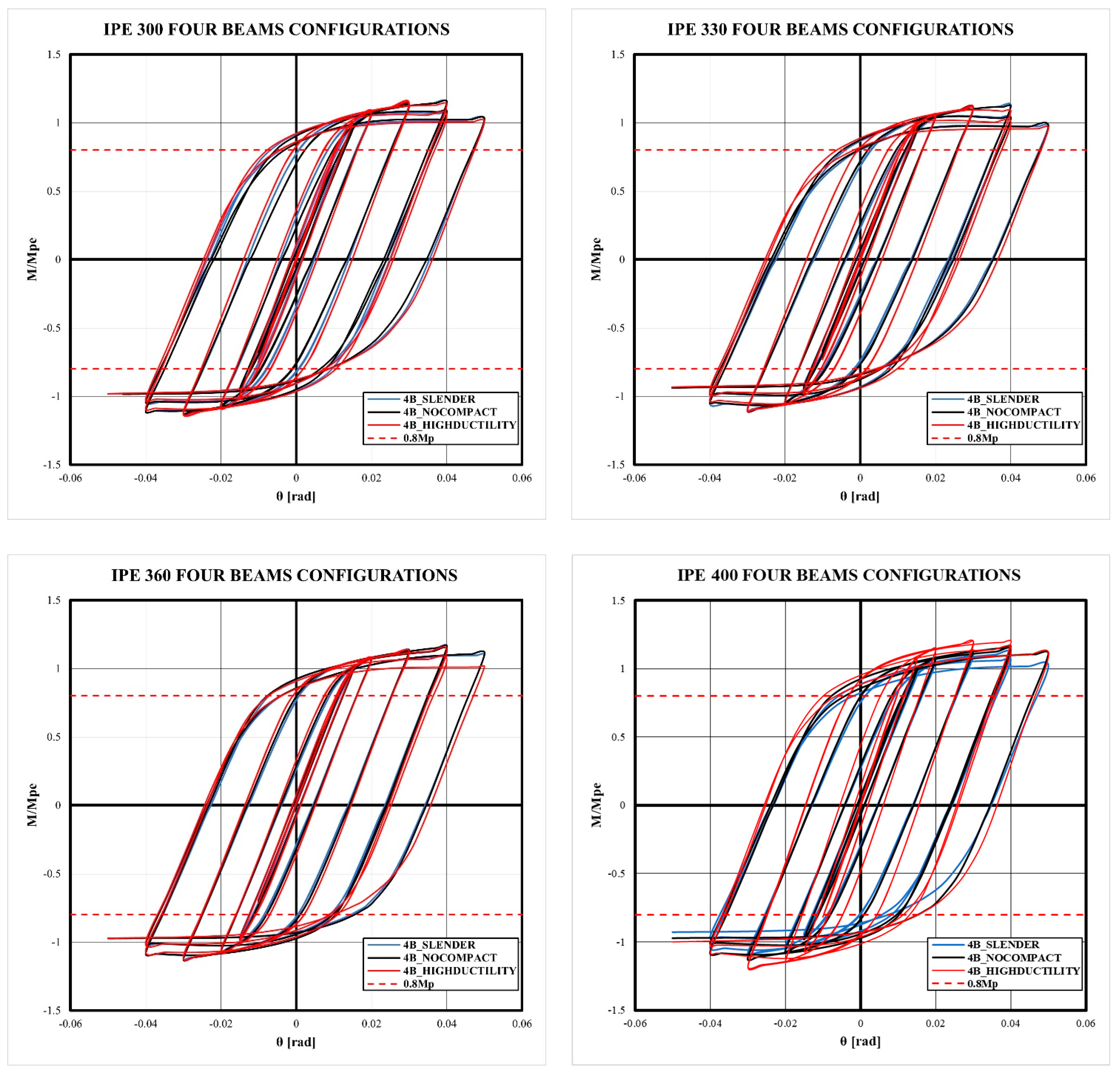
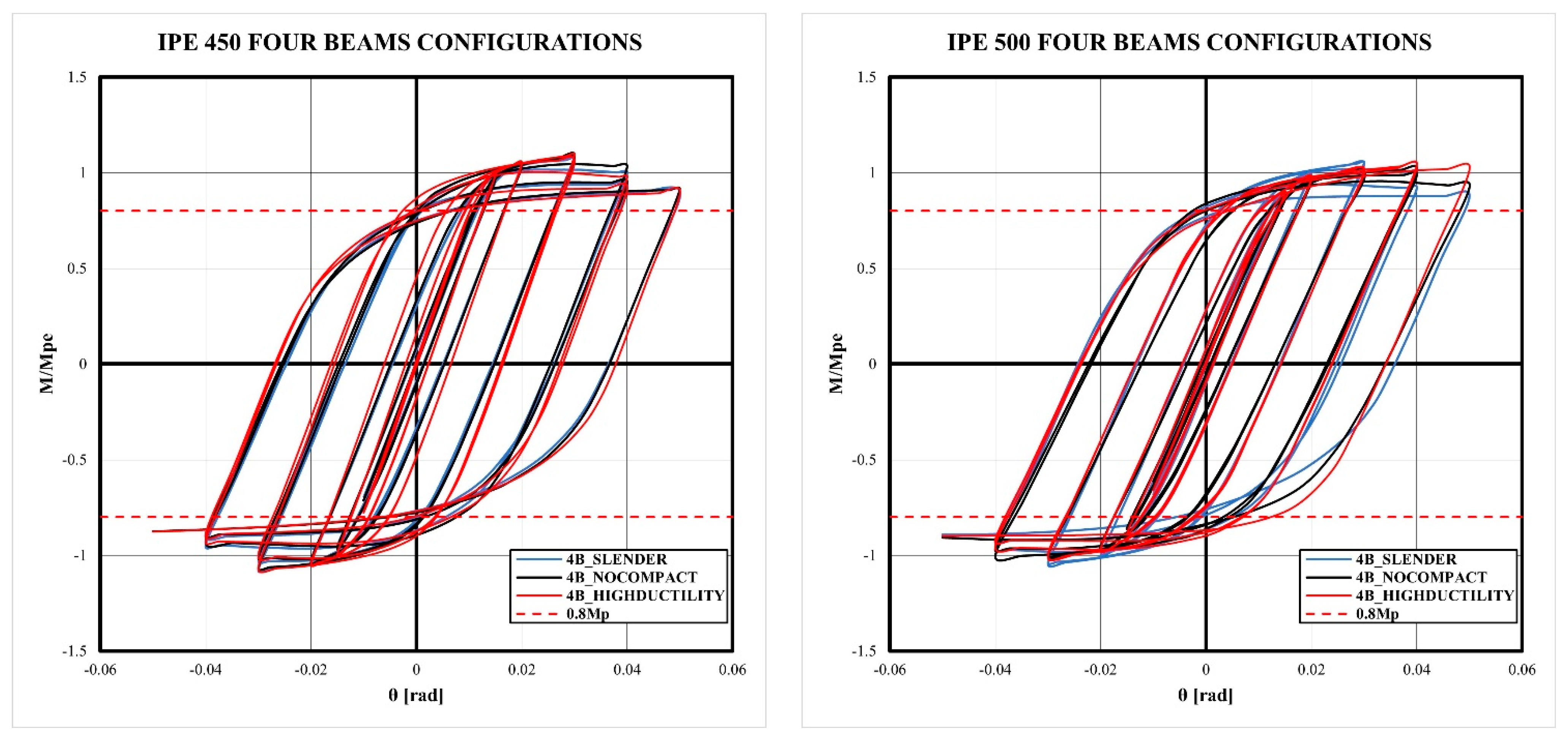
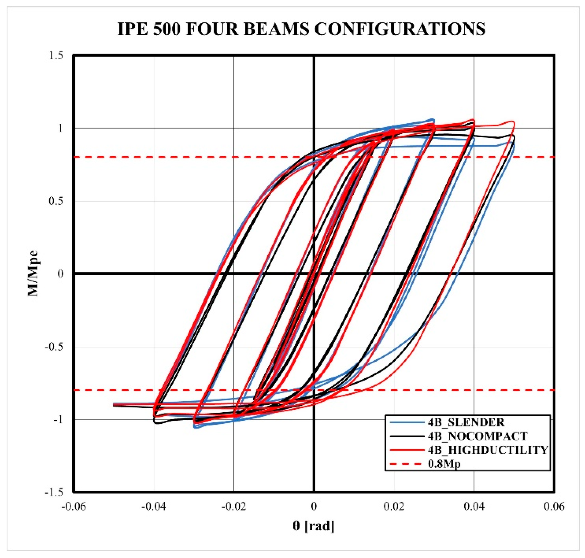
  • The models exhibited a stable cyclic behavior until 0.03 rad of drift, without the loss of strength and stiffness. After this limit, the strength decreased a 10% of the maximum strength for 0.04 rad of drift and 20% for 0.05 rad of drift. However, the flexural strength of 0.8 Mp was reached for 4% of the drift ratio according to the Seismic Provisions.
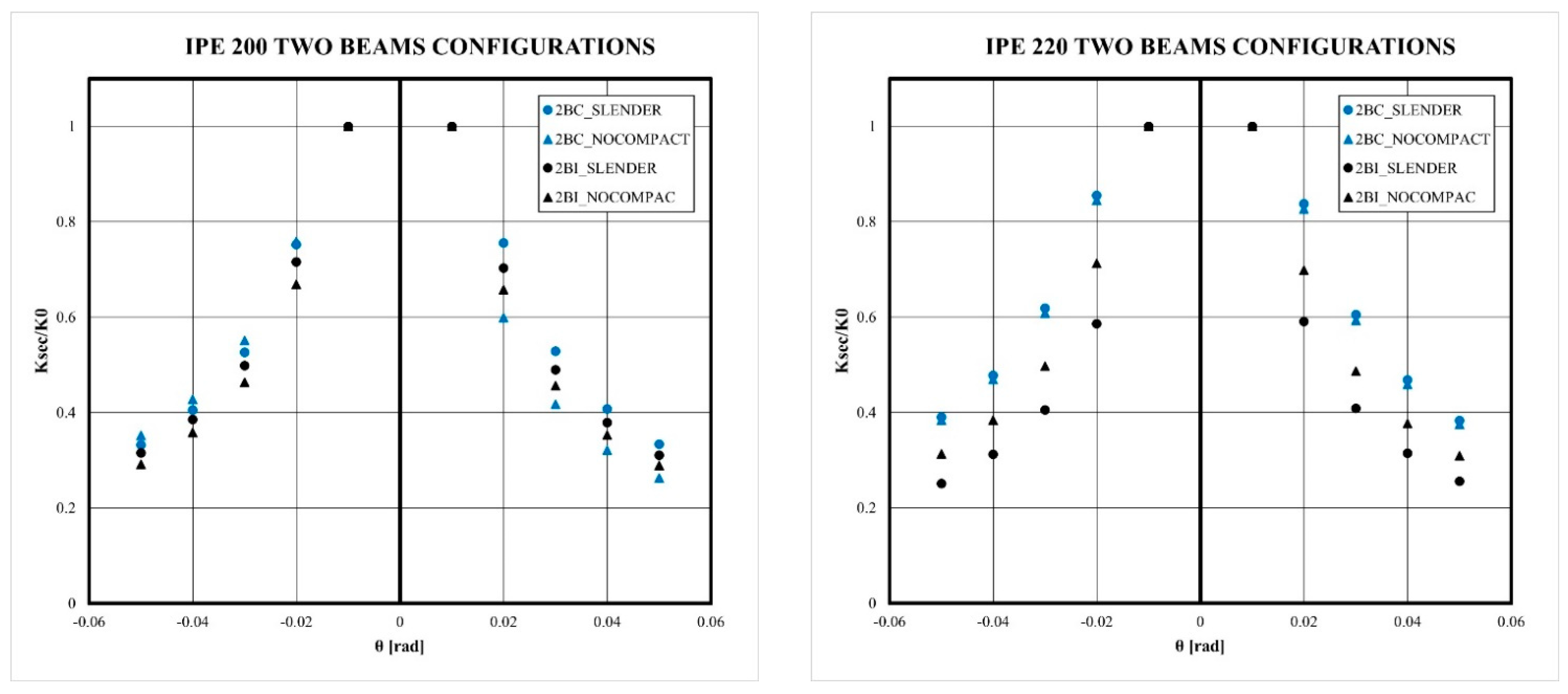
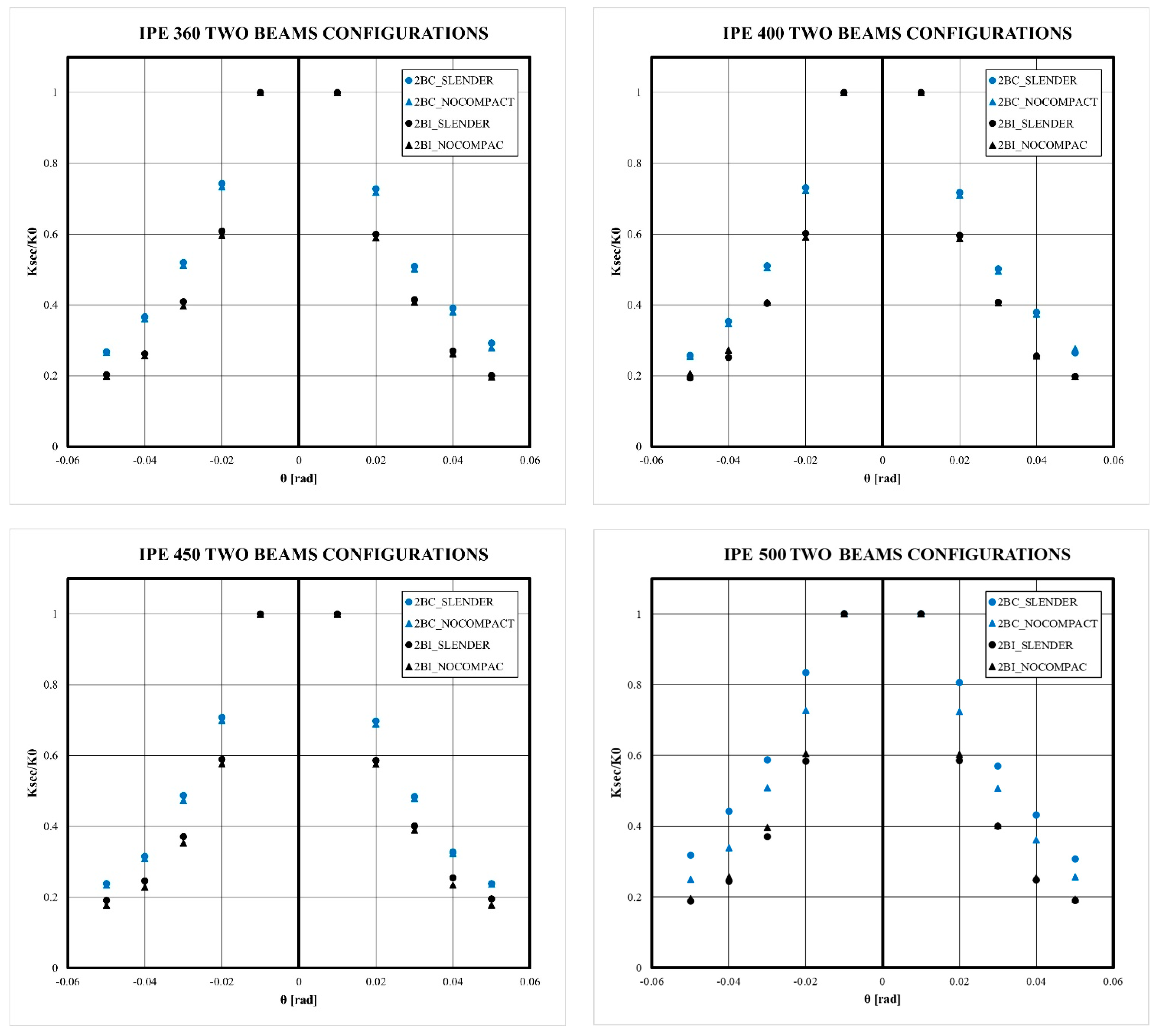
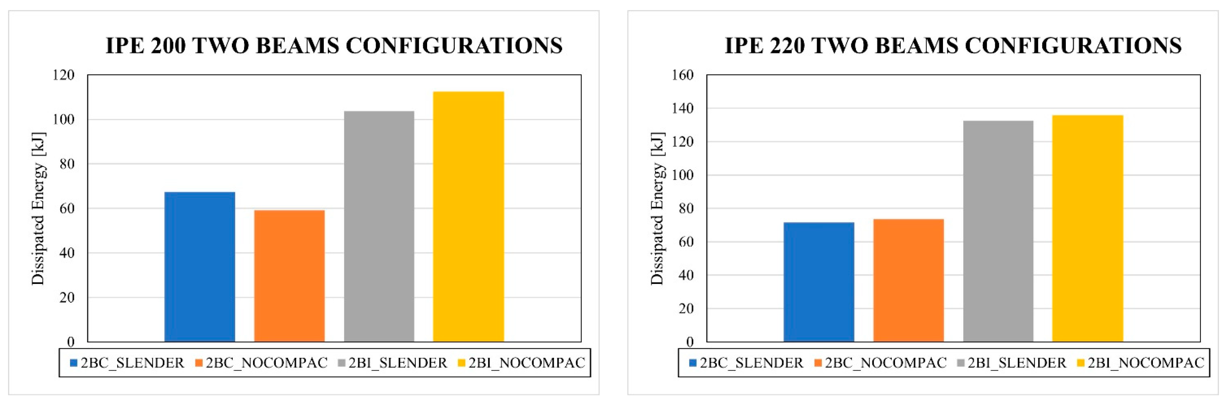
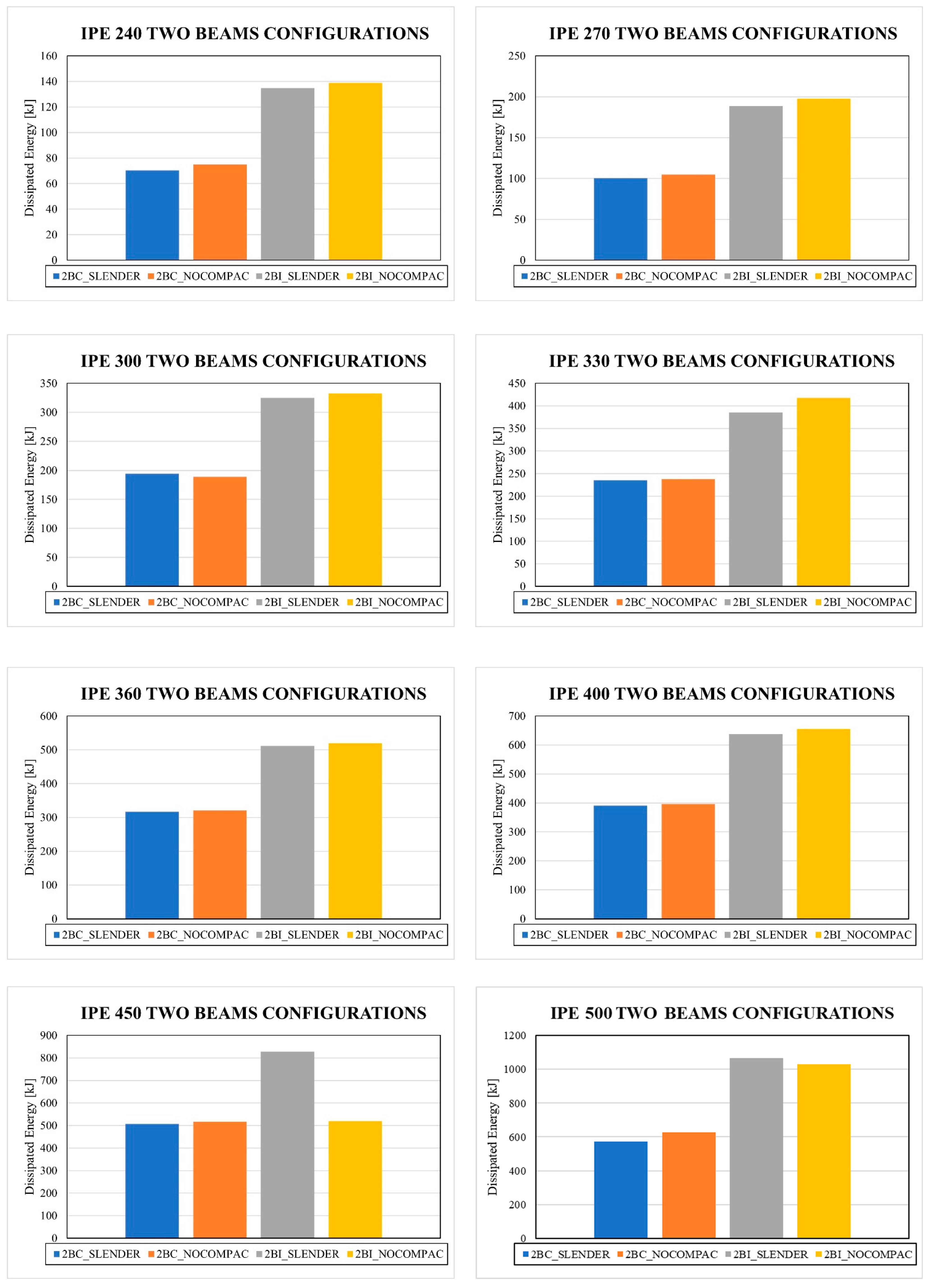
  • Although the bidirectional effect reduces the stiffness and the strength of moment connections with CFT columns, this phenomenon makes it possible to maintain the stability of the hysteretic behavior of the connection, reducing pinching in comparison to the 2BI models. Therefore, 2BI models may develop out-of-plane instability.
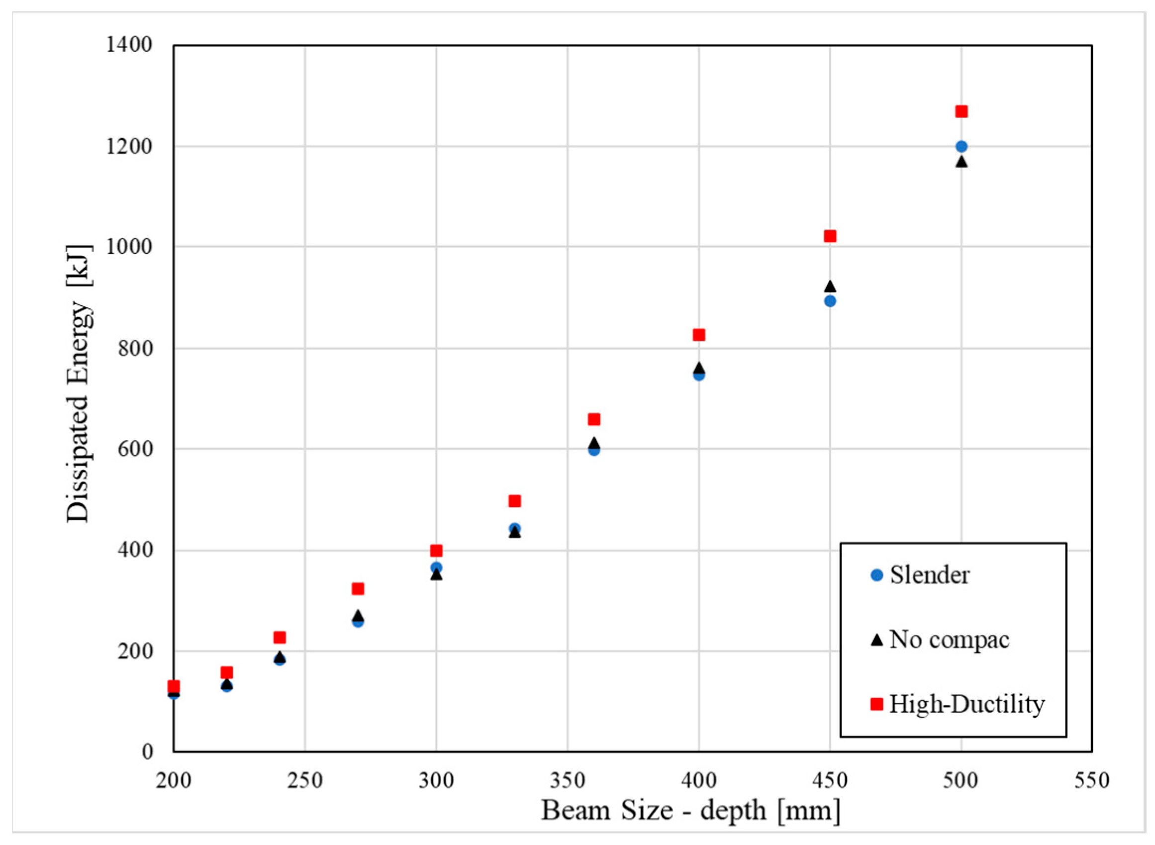
  • The slenderness column effect slightly reduces the strength and the dissipated energy of the connection in comparison to columns with a high-ductility ratio. However, the prequalification limitations according to Chapter K-Seismic Provisions are satisfied.
  • The concrete damages achieved a fracture in concrete for cyclic loads higher than 3% of the drift. This effect was obtained for all models studied. Furthermore, the maximum compression strength was not reached; therefore, the main use of concrete is to avoid deformation by local buckling.

7. Final Remarks

In the current design, the use of slender columns is not allowed according to the Seismic Provisions; however, the joint configurations designed according to the considerations proposed allow the use of concrete-filled columns with a slender wall of tube, in addition to using bidirectional moment connections, avoiding brittle failure mechanisms or column damage to ensure plastic hinges in the beams. On the other hand, the use of concrete with a strength greater than 25 MPa that meets the criteria in ACI-318 [49] is recommended in order to achieve high levels of confinement and plastic deformation, as shown in the results. In this research, the main use of concrete is to avoid the local buckling of the steel tube.
The proposed seismic design of moment frames in seismic zones should consider the design of the web panel zone shear, the number of connected beams, the axial load level, and the SC-WB requirement. Additionally, the verification of drifts must be performed considering the rigidity of the connection. Thus, by fulfilling these requirements, it is possible to create a design that controls the damage in columns and guarantees the failure mechanism in beams.

Author Contributions

Conceptualization, E.N.; methodology, E.N.; software, R.M.; validation, E.N., R.M.; formal analysis, E.N. and R.M.; investigation, R.M.; resources, E.N.; data curation, E.N. and R.M.; writing—original draft preparation, E.N. and R.M.; writing—review and editing, E.N. and R.M.; visualization, E.N. and R.M.; supervision, E.N.; project administration, E.N.; and funding acquisition, E.N. All authors have read and agreed to the published version of the manuscript.

Funding

This research was funded by the Dirección de postgrado de la Universidad Católica de la Santísima Concepción.

Data Availability Statement

Data are contained within the article.

Conflicts of Interest

The authors declare no conflicts of interest.

Appendix A

Figure A1. Comparison of hysteresis curves considering the local slenderness of the column for 2B models.
Buildings 14 02240 g0a1aBuildings 14 02240 g0a1bBuildings 14 02240 g0a1c
Figure A2. Comparison of secant stiffness considering the local slenderness of the column for 2B models.
Buildings 14 02240 g0a2aBuildings 14 02240 g0a2bBuildings 14 02240 g0a2c
Figure A3. Comparison of dissipated energy considering the local slenderness of the column for 2B models.
Buildings 14 02240 g0a3aBuildings 14 02240 g0a3b
Figure A4. Comparison of hysteresis curves considering the local slenderness of the column for 4B models.
Buildings 14 02240 g0a4aBuildings 14 02240 g0a4bBuildings 14 02240 g0a4c
Figure A5. Equivalent plastic strain of 4B models.
Buildings 14 02240 g0a5aBuildings 14 02240 g0a5bBuildings 14 02240 g0a5c
Figure A6. Equivalent von Mises stress for 4B models.
Buildings 14 02240 g0a6aBuildings 14 02240 g0a6bBuildings 14 02240 g0a6c
Figure A7. Plastic strains in concrete material for 4B models.
Buildings 14 02240 g0a7aBuildings 14 02240 g0a7bBuildings 14 02240 g0a7c
Figure A8. Normal stress (vertical direction) in concrete material for 4B models.
Buildings 14 02240 g0a8aBuildings 14 02240 g0a8bBuildings 14 02240 g0a8cBuildings 14 02240 g0a8d

References

  1. Okazaki, T.; Lignos, D.G.; Midorikawa, M.; Ricles, J.M.; Love, J. Damage to steel buildings observed after the 2011 Tohoku-oki earthquake. Earthq. Spectra 2013, 29 (Suppl. 1), 219–243. [Google Scholar] [CrossRef]
  2. Midorikawa, M.; Okazaki, T. Earthquake and tsunami damage to steel structures. In Proceedings of the 2012 Structures Congress, Tokyo, Japan, 1–4 March 2012. [Google Scholar] [CrossRef]
  3. Nishiyama, I.; Yamanouchi, H.; Aoyama, H. U.S.-Japan cooperative earthquake engineering research on composite and hybrid structures. AIJ J. Technol. Des. 1999, 5, 107–110. [Google Scholar] [CrossRef] [PubMed]
  4. Longo, A.; Montuori, R.; Nastri, E.; Piluso, V. On the use of HSS in seismic-resistant structures. J. Constr. Steel Res. 2014, 103, 1–12. [Google Scholar] [CrossRef]
  5. Horikawa, K.; Sakino, Y. Damages to steel structures caused by the 1995 Kobe earthquake. Struct. Eng. Int. J. Int. Assoc. Bridge Struct. Eng. (IABSE) 1996, 6, 181–182. [Google Scholar] [CrossRef]
  6. Xiao, Y.; He, W.; Choi, K. Confined Concrete-Filled Tubular Columns. J. Struct. Eng. 2005, 131, 488–497. [Google Scholar] [CrossRef]
  7. Mao, X.Y.; Xiao, Y. Seismic behavior of confined square CFT columns. Eng. Struct. 2006, 28, 1378–1386. [Google Scholar] [CrossRef]
  8. Goto, Y.; Kumar, G.P.; Kawanishi, N. Nonlinear Finite-Element Analysis for Hysteretic Behavior of Thin-Walled Circular Steel Columns with In-Filled Concrete. J. Struct. Eng. 2010, 136, 1413–1422. [Google Scholar] [CrossRef]
  9. Gajalakshmi, P.; Helena, H.J. Behaviour of concrete-filled steel columns subjected to lateral cyclic loading. J. Constr. Steel Res. 2012, 75, 55–63. [Google Scholar] [CrossRef]
  10. Aydin, F.; Saribiyik, M. Investigation of flexural behaviors of hybrid beams formed with GFRP box section and concrete. Constr. Build. Mater. 2013, 41, 563–569. [Google Scholar] [CrossRef]
  11. Skalomenos, K.A.; Hatzigeorgiou, G.D.; Beskos, D.E. Parameter identification of three hysteretic models for the simulation of the response of CFT columns to cyclic loading. Eng. Struct. 2014, 61, 44–60. [Google Scholar] [CrossRef]
  12. Skalomenos, K.A.; Hayashi, K.; Nishi, R.; Inamasu, H.; Nakashima, M. Experimental Behavior of Concrete-Filled Steel Tube Columns Using Ultrahigh-Strength Steel. J. Struct. Eng. 2016, 142, 04016057. [Google Scholar] [CrossRef]
  13. Wang, Y.T.; Cai, J.; Long, Y.L. Hysteretic behavior of square CFT columns with binding bars. J. Constr. Steel Res. 2017, 131, 162–175. [Google Scholar] [CrossRef]
  14. ANSI/AISC 341-22; Seismic Provisions for Structural Steel Buildings. American Institute of Steel Construction: Chicago, IL, USA, 2022.
  15. Araújo, M.; Macedo, L.; Castro, J.M. Evaluation of the rotation capacity limits of steel members defined in EC8-3. J. Constr. Steel Res. 2017, 135, 11–29. [Google Scholar] [CrossRef]
  16. Ning, K.Y.; Yang, L.; Ban, H.Y.; Sun, Y.N. Experimental and numerical studies on hysteretic behaviour of stainless steel welded box-section columns. Thin-Walled Struct. 2019, 136, 280–291. [Google Scholar] [CrossRef]
  17. Chou, C.C.; Wu, S.C. Cyclic lateral load test and finite element analysis of high-strength concrete-filled steel box columns under high axial compression. Eng. Struct. 2019, 189, 89–99. [Google Scholar] [CrossRef]
  18. ANSI/AISC 358-22; Prequalified Connections for Special and Intermediate Steel Moment Frames for. American Institute of Steel Construction: Chicago, IL, USA, 2022.
  19. Simmons, R.J. Quick-Set, Full-Moment-Lock, Column and Beam Building Frame System and Method. US8453414B2, 4 June 2013. [Google Scholar]
  20. Bock, C.; Bong, W. Moment Resisting Connection Apparatus and Method. 20020124520A1, 12 September 2002. [Google Scholar]
  21. Kang, C.H.; Shin, K.J.; Oh, Y.S.; Moon, T.S. Hysteresis behavior of CFT column to H-beam connections with external T-stiffeners and penetrated elements. Eng. Struct. 2001, 23, 1194–1201. [Google Scholar] [CrossRef]
  22. Varma, A.H.; Ricles, J.M.; Sause, R.; Lu, L.W. Seismic behavior and modeling of high-strength composite concrete-filled steel tube (CFT) beam-columns. J. Constr. Steel Res. 2002, 58, 725–758. [Google Scholar] [CrossRef]
  23. Tizani, W.; Wang, Z.Y.; Hajirasouliha, I. Hysteretic performance of a new blind bolted connection to concrete filled columns under cyclic loading: An experimental investigation. Eng. Struct. 2013, 46, 535–546. [Google Scholar] [CrossRef]
  24. Sheet, I.S.; Gunasekaran, U.; MacRae, G.A. Experimental investigation of CFT column to steel beam connections under cyclic loading. J. Constr. Steel Res. 2013, 86, 167–182. [Google Scholar] [CrossRef]
  25. Qin, Y.; Chen, Z.; Wang, X. Experimental investigation of new internal-diaphragm connections to CFT columns under cyclic loading. J. Constr. Steel Res. 2014, 98, 35–44. [Google Scholar] [CrossRef]
  26. Qin, Y.; Chen, Z.; Bai, J.; Li, Z. Test of extended thick-walled through-diaphragm connection to thick-walled CFT column. Steel Compos. Struct. 2016, 20, 1–12. [Google Scholar] [CrossRef]
  27. Vulcu, C.; Stratan, A.; Ciutina, A.; Dubina, D. Beam-to-CFT High-Strength Joints with External Diaphragm. I: Design and Experimental Validation. J. Struct. Eng. 2017, 143, 04017001. [Google Scholar] [CrossRef]
  28. Azar, A.S.; Shaghaghi, T.M. Seismic behavior of conxl connections in concrete filled steel Tube Columns (CFT). J. Fundam. Appl. Sci. 2017, 9, 217. [Google Scholar] [CrossRef]
  29. Koloo, F.A.; Badakhshan, A.; Fallahnejad, H.; Jamkhaneh, M.E.; Ahmadi, M. Investigation of Proposed Concrete Filled Steel Tube Connections under Reversed Cyclic Loading. Int. J. Steel Struct. 2018, 18, 163–177. [Google Scholar] [CrossRef]
  30. Rezaifar, O.; Younesi, A. Experimental study discussion of the seismic behavior on new types of internal/external stiffeners in rigid beam-to-CFST/HSS column connections. Constr. Build. Mater. 2017, 136, 574–589. [Google Scholar] [CrossRef]
  31. Lai, Z.; Fischer, E.C.; Varma, A.H. Database and Review of Beam-to-Column Connections for Seismic Design of Composite Special Moment Frames. J. Struct. Eng. 2019, 145, 04019023. [Google Scholar] [CrossRef]
  32. Fanaie, N.; Moghadam, H.S. Experimental study of rigid connection of drilled beam to CFT column with external stiffeners. J. Constr. Steel Res. 2019, 153, 209–221. [Google Scholar] [CrossRef]
  33. Parvari, A.; Zahrai, S.M.; Mirhosseini, S.M.; Zeighami, E. Numerical and experimental study on the behavior of drilled flange steel beam to CFT column connections. Structures 2020, 28, 726–740. [Google Scholar] [CrossRef]
  34. Ahmadi, M.M.; Mirghaderi, S.R. Experimental studies on through-plate moment connection for beam to HSS/CFT column. J. Constr. Steel Res. 2019, 161, 154–170. [Google Scholar] [CrossRef]
  35. Parvari, A.; Zahrai, S.M.; Mirhosseini, S.M.; Zeighami, E. Comparing cyclic behaviour of RBS, DFC and proposed rigid connections in a steel moment frame with CFT column. Aust. J. Civ. Eng. 2021, 19, 164–183. [Google Scholar] [CrossRef]
  36. Jeddi, M.Z.; Sulong, N.H.R.; Ghanbari-Ghazijahani, T. Behaviour of double-sleeve TubeBolt moment connections in CFT columns under cyclic loading. J. Constr. Steel Res. 2022, 194, 107302. [Google Scholar] [CrossRef]
  37. Paul, S.; Deb, S.K. Experimental study on a new V-cut RBS and CFT connections with bidirectional bolts under cyclic loadings. J. Build. Eng. 2022, 46, 103688. [Google Scholar] [CrossRef]
  38. Du, H.; Zhao, P.; Wang, Y.; Sun, W. Seismic experimental assessment of beam-through beam-column connections for modular prefabricated steel moment frames. J. Constr. Steel Res. 2022, 192, 107208. [Google Scholar] [CrossRef]
  39. Habibi, A.; Fanaie, N.; Shahbazpanahi, S. Experimental and numerical investigation of I-beam to concrete-filled tube (CFT) column moment connections with pipe-stiffened internal diaphragm. J. Constr. Steel Res. 2023, 200, 107648. [Google Scholar] [CrossRef]
  40. Razavi, S.A.; Kandi, A.H.; Alimardani, M.; Jovaini, E. Tube-in-tube rigid beam to CFT column connection in moment-resisting frames: An experimental study. Soil Dyn. Earthq. Eng. 2023, 171, 107901. [Google Scholar] [CrossRef]
  41. Bai, Y.; Wang, S.; Mou, B.; Wang, Y.; Skalomenos, K.A. Bi-directional seismic behavior of steel beam-column connections with outer annular stiffener. Eng. Struct. 2021, 227, 111443. [Google Scholar] [CrossRef]
  42. Gallegos, M.; Nuñez, E.; Herrera, R. Numerical study on cyclic response of end-plate biaxial moment connection in box columns. Metals 2020, 10, 523. [Google Scholar] [CrossRef]
  43. Mata, R.; Nuñez, E. Parametric study of 3D steel moment connections with built-up box column subjected to biaxial cyclic loads. J. Constr. Steel Res. 2022, 197, 107453. [Google Scholar] [CrossRef]
  44. Nuñez, E.; Torres, R.; Herrera, R. Seismic performance of moment connections in steel moment frames with HSS columns. Steel Compos. Struct. 2017, 25, 271–286. [Google Scholar] [CrossRef]
  45. Mata, R.; Nuñez, E.; Sanhueza, F.; Maureira, N.; Roco, Á. Assessment of Web Panel Zone in Built-up Box Columns Subjected to Bidirectional Cyclic Loads. Buildings 2023, 13, 71. [Google Scholar] [CrossRef]
  46. Nuñez-Castellanos, E.; Bustos-Figueroa, J.; Mata-Lemus, R.; Sanhueza-Espinoza, F.; Lapeña-Mañero, P. Cyclic behavior of 3D moment connections subjected to bidirectional load: Experimental approach. Eng. Struct. 2023, 291, 116392. [Google Scholar] [CrossRef]
  47. ANSYS Inc. ANSYS v2022; ANSYS Inc.: Canonsburg, PA, USA, 2022. [Google Scholar]
  48. ANSI/AISC 360-22; Specification for Structural Steel Buildings. American Institute of Steel Construction: Chicago, IL, USA, 2022.
  49. ACI Committee 318. Building Code Requirements for Structural Concrete (ACI 318-19) and Commentary (ACI 318R-19); American Concrete Institute: Indianapolis, IN, USA, 2019. [Google Scholar]
  50. Nuñez, E.; Mata, R. Strong column-weak beam relationship of 3D steel joints with tubular columns: Assessment, Validation and Design proposal. J. Build. Eng. 2024, 82, 108399. [Google Scholar] [CrossRef]
  51. Gerbens-Leenes, P.W.; Hoekstra, A.Y.; Bosman, R. The blue and grey water footprint of construction materials: Steel, cement and glass. Water Resour. Ind. 2018, 19, 1–12. [Google Scholar] [CrossRef]
  52. Vilela, P.M.L.; Carvalho, H.; Grilo, L.F.; Montenegro, P.A.; Calçada, R.B. Unitary model for the analysis of bolted connections using the finite element method. Eng. Fail Anal. 2019, 104, 308–320. [Google Scholar] [CrossRef]
  53. Zreid, I.; Kaliske, M. A gradient enhanced plasticity–damage microplane model for concrete. Comput. Mech. 2018, 62, 1239–1257. [Google Scholar] [CrossRef]
  54. Jiang, J.F.; Wu, Y.F. Identification of material parameters for Drucker-Prager plasticity model for FRP confined circular concrete columns. Int. J. Solids Struct. 2012, 49, 445–456. [Google Scholar] [CrossRef]
  55. Kedziora, S.; Anwaar, M.O. Concrete-filled steel tubular (CFTS) columns subjected to eccentric compressive load. AIP Conf. Proc. 2019, 2060, 020004. [Google Scholar] [CrossRef]
  56. Bayraktar, A.; Şahin, A.; Özcan, D.M.; Yildirim, F. Numerical damage assessment of Haghia Sophia bell tower by nonlinear FE modeling. Appl. Math. Model. 2010, 34, 92–121. [Google Scholar] [CrossRef]
  57. Avci, O.; Bhargava, A. Finite-Element Analysis of Cantilever Slab Deflections with ANSYS SOLID65 3D Reinforced-Concrete Element with Cracking and Crushing Capabilities. Pract. Period. Struct. Des. Constr. 2019, 24, 05018007. [Google Scholar] [CrossRef]
  58. Schneider, S.P. Axially Loaded Concrete-Filled Steel Tubes. J. Struct. Eng. 1998, 124, 1125–1138. [Google Scholar] [CrossRef]
  59. Gupta, P.K.; Khaudhair, Z.; Ahuja, A.K. 3D numerical simulation of concrete filled steel tubular columns using ANSYS. In UKIERI Concrete Congress—Innovation in Concrete Construction; Jalandhar, India; 2013; pp. 2262–2271. Available online: https://www.researchgate.net/publication/317380097_3D_NUMERICAL_SIMULATION_OF_CONCRETE_FILLED_STEEL_TUBULAR_COLUMNS_USING_ANSYS (accessed on 25 February 2024).
  60. Tartaglia, R.; D’Aniello, M.; Rassati, G.A.; Swanson, J.A.; Landolfo, R. Full strength extended stiffened end-plate joints: AISC vs recent European design criteria. Eng. Struct. 2018, 159, 155–171. [Google Scholar] [CrossRef]
  61. ASTM Committee. Standard Specification for General Requirements for Rolled Structural Steel Bars, Plates, Shapes, and Sheet Piling; American Society for Testing and Materials (ASTM): West Conshohocken, PA, USA, 2001. [Google Scholar]
  62. A1085/A1085M−15; Standard Specification for Cold-Formed Welded Carbon Steel Hollow Structural Sections (HSS). American Society for Testing and Materials (ASTM): West Conshohocken, PA, USA, 2015.
  63. Behrooz, S.M.; Erfani, S. Parametric study of Stub-Beam Bolted Extended End-Plate connection to box-columns. J. Constr. Steel Res. 2020, 171, 106155. [Google Scholar] [CrossRef]
  64. Goudarzi, A.; Erfani, S. Seismic performance of beam to box-column connection by a short stub beam. J. Constr. Steel Res. 2022, 190, 107145. [Google Scholar] [CrossRef]
  65. Wei, J.P.; Tian, L.M.; Guo, Y.; Qiao, H.Y.; Bao, Y.; Jiao, Z.A.; Shi, X.J. Numerical study of the seismic performance of a double-hinge steel frame joint. J. Constr. Steel Res. 2021, 187, 106963. [Google Scholar] [CrossRef]
  66. Zhang, A.L.; Qiu, P.; Guo, K.; Jiang, Z.Q.; Wu, L.; Liu, S.C. Experimental study of earthquake-resilient end-plate type prefabricated steel frame beam-column joint. J. Constr. Steel Res. 2020, 166, 105927. [Google Scholar] [CrossRef]
  67. Torres-Rodas, P.; Medalla, M.; Zareian, F.; Lopez-Garcia, D. Cyclic behavior and design methodology of exposed base plates with extended anchor bolts. Eng. Struct. 2022, 260, 114235. [Google Scholar] [CrossRef]
  68. Trautner, C.A.; Hutchinson, T.; Grosser, P.R.; Silva, J.F. Effects of Detailing on the Cyclic Behavior of Steel Baseplate Connections Designed to Promote Anchor Yielding. J. Struct. Eng. 2016, 142, 04015117. [Google Scholar] [CrossRef]
  69. Chopra, A.K. Dynamic of Structures; Pearsons: London, UK, 2012. [Google Scholar]
  70. Wu, L.Y.; Chung, L.L.; Tsai, S.F.; Lu, C.F.; Huang, G.L. Seismic behavior of bidirectional bolted connections for CFT columns and H-beams. Eng. Struct. 2007, 29, 395–407. [Google Scholar] [CrossRef]
  71. Li, X.; Xiao, Y.; Wu, Y.T. Seismic behavior of exterior connections with steel beams bolted to CFT columns. J. Constr. Steel Res. 2009, 65, 1438–1446. [Google Scholar] [CrossRef]
  72. Rahnavard, R.; Hassanipour, A.; Siahpolo, N. Analytical study on new types of reduced beam section moment connections affecting cyclic behavior. Case Stud. Struct. Eng. 2015, 3, 33–51. [Google Scholar] [CrossRef]
Figure 1. (a) Geometrical limitation of external diaphragms, (b) 2BC joint configuration, (c) 2BI joint configuration, and (d) 4B joint configuration.
Buildings 14 02240 g001
Figure 2. Boundary and loading conditions applied in the numerical model.
Buildings 14 02240 g002
Figure 3. Calibration of the concrete model from experimental data. (a) Failure mechanism of the calibrated model. (b) Calibration curve with experimental data from [58].
Buildings 14 02240 g003
Figure 4. Mesh used in numerical models.
Buildings 14 02240 g004
Figure 5. Calibration of the numerical model with Test #3 [46].
Buildings 14 02240 g005
Figure 6. Plastic strain distribution for the (a) adt-01, (b) adt-02, (c) high-ductility CFT, and (d) slender CFT proposed.
Buildings 14 02240 g006
Figure 7. Comparison of hysteresis curves considering the local slenderness of the column for 2B models.
Buildings 14 02240 g007
Figure 8. Comparison of secant stiffness considering the local slenderness of the column for 2B models.
Buildings 14 02240 g008
Figure 9. Comparison of dissipated energy considering the local slenderness of the column for 2B models.
Buildings 14 02240 g009
Figure 10. Comparison of hysteresis curves considering the local slenderness of the column for 4B models.
Buildings 14 02240 g010
Figure 11. Equivalent plastic strain of 4B models.
Buildings 14 02240 g011
Figure 12. Equivalent von Mises stress for 4B models.
Buildings 14 02240 g012
Figure 13. Comparison of the total dissipated energy for 4B models.
Buildings 14 02240 g013
Figure 14. Uncertainty assessment analysis for the moment at 0.04 rad of drift.
Buildings 14 02240 g014
Figure 15. Plastic strains in concrete material for 4B models.
Buildings 14 02240 g015
Figure 16. Normal stress (vertical direction) in concrete material for 4B models.
Buildings 14 02240 g016
Figure 17. Rupture index for IPE 450 slender models.
Buildings 14 02240 g017
Figure 18. Average rupture index for all models’ configurations.
Buildings 14 02240 g018
Table 1. Results of the designed models.
BeamColumnSpan between Columns (m)Bolt Diameter (in)End Plate Thickness (mm)Horizontal Stiffener Thickness (mm)Vertical Stiffener Thickness Vertical (mm)Ratio WPZS (Panel Zone)
SectionSteelSection SlenderSection Non-CompactSection High-DuctilitySteel
IPE-200A-36425 × 425 × 4425 × 425 × 6425 × 425 × 14A-362.43/4″201660.93
IPE-220A-36450 × 450 × 5450 × 450 × 6450 × 450 × 14A-362.647/8″221680.90
IPE-240A-36500 × 500 × 5500 × 500 × 6500 × 500 × 16A-362.887/8″251880.89
IPE-270A-36525 × 525 × 6525 × 525 × 8525 × 525 × 16A-363.241″252080.88
IPE-300A-36575 × 575 × 6575 × 575 × 8575 × 575 × 18A-363.61″282280.87
IPE-330A-36625 × 625 × 6625 × 625 × 8625 × 625 × 18A-363.961 1/8″282580.87
IPE-360A-36700 × 700 × 8700 × 700 × 10700 × 700 × 22A-364.321 1/4″3828100.74
IPE-400A-36750 × 750 × 8750 × 750 × 10750 × 750 × 22A-364.81 1/4″3830100.75
IPE-450A-36825 × 825 × 8825 × 825 × 10825 × 825 × 25A-365.41 3/8″4038100.72
IPE-500A-36875 × 875 × 10875 × 875 × 12875 × 875 × 28A-3661 1/2″5038100.68
Table 2. Summary of the studied models.
Beam/ConfigurationColumn Slender CFTColumn Non-Compact CFTColumn High-Ductility CFT
2BC2BI4B2BC2BI4B4BTotal
IPE-20011111117
IPE-22011111117
IPE-24011111117
IPE-27011111117
IPE-30011111117
IPE-33011111117
IPE-36011111117
IPE-40011111117
IPE-45011111117
IPE-50011111117
Total1010101010101070
Table 3. Mechanical characteristics of materials derived from tests [46], transformed into true values.
MaterialFy (MPa)εy (mm/mm)Fu (MPa)εu (mm/mm)
ASTM A36320.330.0014017441.670.1036
ASTM A-325627.450.00393934.320.1601
Table 4. Type of contact interaction by element in the numerical model.
Interaction Contact ZoneType of Contact
1End Plate–End PlateFrictional μ = 0.3
2Bolt shank–End PlateFrictional μ = 0.3
3Bolt shank–Bolt headBonded
4Bolt head–End PlateFrictional μ = 0.3
5Bolt shank–NutBonded
6Nut–End PlateFrictional μ = 0.3
7End Plate–Horizontal DiaphragmBonded
8End Plate–Vertical StiffenerBonded
9Horizontal Diaphragm–Vertical StiffenerBonded
10Horizontal Diaphragm–ColumnBonded
11End Plate–BeamBonded
12Beam–BeamBonded
13Column Plates–Column PlatesBonded
14Column Plates–Concrete CoreFrictional μ = 0.6
Table 5. Summary of the key parameters for the studied models.
Beam SizeJoint ConfigurationSlenderness RatioMax Lateral Load (kN)M0.04/MpM Max/Mpθmax (rad)Initial Stiffness West Beam (kN·m/rad)Dissipated Energy (kJ)
IPE-2002BCSlender73,1501.0841.1090.0506,489,48067,406
Non-compact82,0591.1091.1090.0508,424,60059,053
2BISlender86,8171.1131.1410.0507,277,120103,647
Non-compact87,3961.1171.1430.0507,980,777112,484
4BSlender127,1001.0861.1110.0506,730,320131,587
Non-compact124,7901.0791.1040.0506,051,840115,365
High-ductility127,6501.0811.1060.0506,036,240122,743
IPE-2202BCSlender69,7041.0731.0980.0507,239,01271,640
Non-compact70,1561.0751.1000.0507,401,37273,453
2BISlender106,7701.1181.1330.0509,213,502132,523
Non-compact103,4801.1101.1380.0509,359,856135,814
4BSlender147,6301.0691.1200.0506,710,939130,802
Non-compact148,1101.0721.0960.0506,943,929136,508
High-ductility151,2701.0781.1020.0507,785,917157,828
IPE-2402BCSlender82,0901.0761.0990.0509,737,13670,330
Non-compact86,5491.2161.2160.04011,312,20874,899
2BISlender120,4001.1001.1000.04012,247,776134,874
Non-compact120,5401.1001.1000.04012,377,664138,819
4BSlender172,4301.0721.0970.0509,213,840183,422
Non-compact172,5201.0701.0910.0509,427,824189,265
High-ductility 185,4701.2201.2480.05011,973,168228,389
IPE-2702BCSlender104,3601.0621.0620.05013,470,462106,096
Non-compact105,4001.0641.0690.05013,974,120143,525
2BISlender152,1201.0501.0550.05016,856,100242,183
Non-compact152,6201.0371.0570.05017,507,340251,553
4BSlender217,6001.0591.0790.05012,725,748258,978
Non-compact219,1801.0611.0770.05013,335,516272,294
High-ductility 229,9201.1841.2040.05017,126,640324,394
IPE-3002BCSlender132,1301.1221.1350.05019,509,660194,437
Non-compact131,7301.1341.1340.05020,172,600188,772
2BISlender184,5500.9391.0620.05022,271,544324,591
Non-compact183,9600.9471.0590.05022,813,200332,266
4BSlender270,0401.1381.1380.05019,376,010366,289
Non-compact270,4901.1481.1480.05019,405,549353,614
High-ductility270,1601.1261.1350.05021,826,800398,715
IPE-3302BCSlender145,3201.1091.1120.05025,256,880235,315
Non-compact145,5701.0951.1070.05025,664,760238,151
2BISlender206,3000.9071.0410.05028,700,100385,390
Non-compact207,3700.8901.0230.05031,345,380417,632
4BSlender302,4401.1211.1210.05024,550,020444,289
Non-compact303,0201.1171.1170.05024,771,780436,629
High-ductility 305,1701.0811.1100.05027,707,460497,868
IPE-3602BCSlender163,2601.1571.1570.05034,097,040316,829
Non-compact163,3301.1411.1410.05034,749,360320,434
2BISlender234,5000.9311.0710.05040,690,080511,352
Non-compact234,5400.9201.0720.05040,992,994519,173
4BSlender343,2901.1571.1570.05031,680,720598,759
Non-compact343,5501.1581.1580.05032,365,440613,515
High-ductility 378,3301.1311.1310.05033,274,800658,428
IPE-4002BCSlender191,4201.1081.1080.05043,903,200390,951
Non-compact191,7001.1071.1070.05044,624,800396,125
2BISlender276,3800.8711.0400.05050,081,720638,187
Non-compact277,3000.8831.0510.05052,508,800655,127
4BSlender403,4201.1101.1100.05041,503,200746,655
Non-compact404,0101.1111.1110.05042,305,600761,987
High-ductility 406,3901.1941.1940.05050,238,067826,726
IPE-4502BCSlender227,4700.9791.0880.05056,189,700507,024
Non-compact218,6600.9811.0880.05056,891,700517,100
2BISlender327,4100.8801.0270.05064,810,800827,266
Non-compact319,2700.8501.0080.05068,096,100519,173
4BSlender476,0000.9971.0830.05053,592,823898,216
Non-compact462,0401.0271.0860.05055,668,600986,388
High-ductility 480,2800.9761.0920.05061,230,6001,071,928
IPE-5002BCSlender257,8501.0141.0140.05057,042,000571,528
Non-compact324,9501.0231.0780.05068,831,840627,984
2BISlender388,8000.8471.0400.05078,791,1001,066,038
Non-compact389,0300.8401.0630.05080,298,0001,030,614
4BSlender560,0700.9991.0520.05057,494,8501,199,222
Non-compact551,8301.0191.0190.05060,936,0001,170,716
High-ductility 556,6701.0401.0400.05065,319,0001,269,456
Disclaimer/Publisher’s Note: The statements, opinions and data contained in all publications are solely those of the individual author(s) and contributor(s) and not of MDPI and/or the editor(s). MDPI and/or the editor(s) disclaim responsibility for any injury to people or property resulting from any ideas, methods, instructions or products referred to in the content.

