Abstract
With the advancement of urban underground space networks, there has been a rise in foundation pit projects near existing tunnels. The construction of these foundation pits adjacent to existing tunnels can result in soil disturbance and stress redistribution, leading to additional deformation and internal force within the tunnels. This paper delves into the two-stage analysis method, outlining the calculation of additional stress in the initial stage considering various engineering factors and the methods for determining tunnel displacement and internal force in the subsequent stage. Through an engineering example and numerical simulations, the theoretical calculations were validated. The maximum displacement generated by the tunnel is −4.85 mm and −5.10 mm, respectively. The maximum error is only 5.9%, which confirms the validity of the theoretical approach. The analysis demonstrates that incorporating the unloading model of the bottom and surrounding side walls of the foundation pit is essential when calculating additional stress in the first stage. Moreover, the presence of engineering dewatering and double-hole tunnels can counterbalance the additional stress, with deviations of only 4.4% and 2.5%, respectively. In the second stage, factoring in the shear action and lateral soil action in the foundation and tunnel model enhances the accuracy of stress mode representation (accuracy increased by 18.8% and 29.3%, respectively). Additionally, accounting for the buried depth effect of the tunnel, soil non-uniformity, and foundation nonlinearity helps prevent excessive foundation reactions.
1. Introduction
The development of urban underground space has evolved from single, isolated structures to more complex and interconnected systems. As construction near existing underground structures increases, new foundation pits are becoming more common. Excavating these pits can impact the stress, deformation, and functionality of existing underground structures, potentially leading to engineering accidents. For instance, the collapse of a municipal channel foundation pit in Wuhan [1] resulted in multiple fractures of underground pipelines. Another example is the Nicoll Highway foundation pit accident in the Singapore Metro [2], which caused damage to a 100 m open-cut tunnel, damage to four fatalities, urban pipeline damage, and the collapse of the Nicoll fast track. To minimize these risks and prevent similar accidents, it is essential to conduct thorough research on how existing structures respond to foundation pit construction.
Only up to 2020, research methods for this issue, both domestically and internationally, could be classified into four main categories. The first category involves the numerical calculation method, where researchers establish models using numerical software, select relevant parameters, and conduct numerical simulation analyses of foundation pit construction [3,4,5,6,7]. The second category is the field measurement method, which includes the field testing of existing engineering projects and the analysis of the collected data to understand the influence law [8,9,10,11,12]. The third category is the model test method, where researchers conduct scale tests using similarity relationships, monitor real-time data during the test process, and analyze the data obtained through monitoring [13,14,15,16,17]. The fourth category involves theoretical analysis, where researchers analyze previous data, deduce relevant formulas, or simplify tunnel analysis using relevant theories based on basic assumptions [18,19,20,21,22]. Theoretical analysis is considered simpler and faster compared to other methods, making it more suitable for preliminary design and guiding engineering construction. The two-stage analysis method is commonly used within theoretical analysis. Numerous scholars both domestically and internationally have conducted research on two-stage analysis methods. For example, Liu et al. [23] established a theoretical calculation model for the uplift deformation of the underlying tunnel caused by the excavation of foundation pits and found that the predicted results were basically consistent with the on-site measured results; Zhou et al. [24] used the incremental method to analyze the interaction between the support structure and the soil and found that the impact range of foundation pit construction on the underlying tunnel is about six times the excavation length; Zhou Zelin et al. [25] considered the effect of engineering precipitation on the deformation of existing tunnels, and the research results showed that excavation-related precipitation is a favorable factor in controlling the uplift of existing underlying tunnels. Although some research has been conducted through theoretical analysis methods, most of them are focused on underground tunnels, and there is relatively little theoretical research on the impact of excavation on side tunnels.
This paper analyzes and summarizes the calculation of additional stress in the first stage under various engineering factors, as well as the calculation method and research conclusions on the displacement and internal force of tunnel structures in the second stage. The vertical displacement distribution law of the side tunnel structure caused by the excavation of foundation pits was analyzed, and it was verified by using numerical simulation methods. By comparing research results from the two-stage analysis method, the paper identifies some advantages and disadvantages of the current approach, offering valuable insights for future scholars.
2. Two-Stage Analysis Method
The current method for theoretically analyzing the mechanical response of an existing tunnel structure due to the excavation of a foundation pit typically involves a two-stage analysis. In the first stage, the stress field theory of existing soil is used to calculate the vertical additional stress at the axis of the tunnel, assuming the tunnel does not exist. In the second stage, the tunnel structure is treated as an infinite beam on an elastic foundation, and the vertical additional stress calculated in the first stage is applied to the tunnel to solve for its deformation and internal forces analytically. A diagram illustrating the process of this two-stage analysis method can be seen in Figure 1.
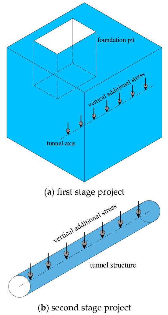
Figure 1.
The schematic diagram of the solution process of the two-stage analysis method.
The method for addressing additional stress in the first stage of the two-stage analysis primarily relies on the unloading model of the bottom and side walls of the foundation pit, following established stress solutions. In the second stage, addressing tunnel displacement and internal force is predominantly based on the tunnel–foundation interaction model, with the corresponding mechanical equilibrium differential equation being established for calculation. Various scholars have incorporated multiple engineering factors into the calculation process, enhancing the accuracy of determining additional stress [26], displacement [27], and internal force [28].
3. Additional Stress Calculation of the First Stage
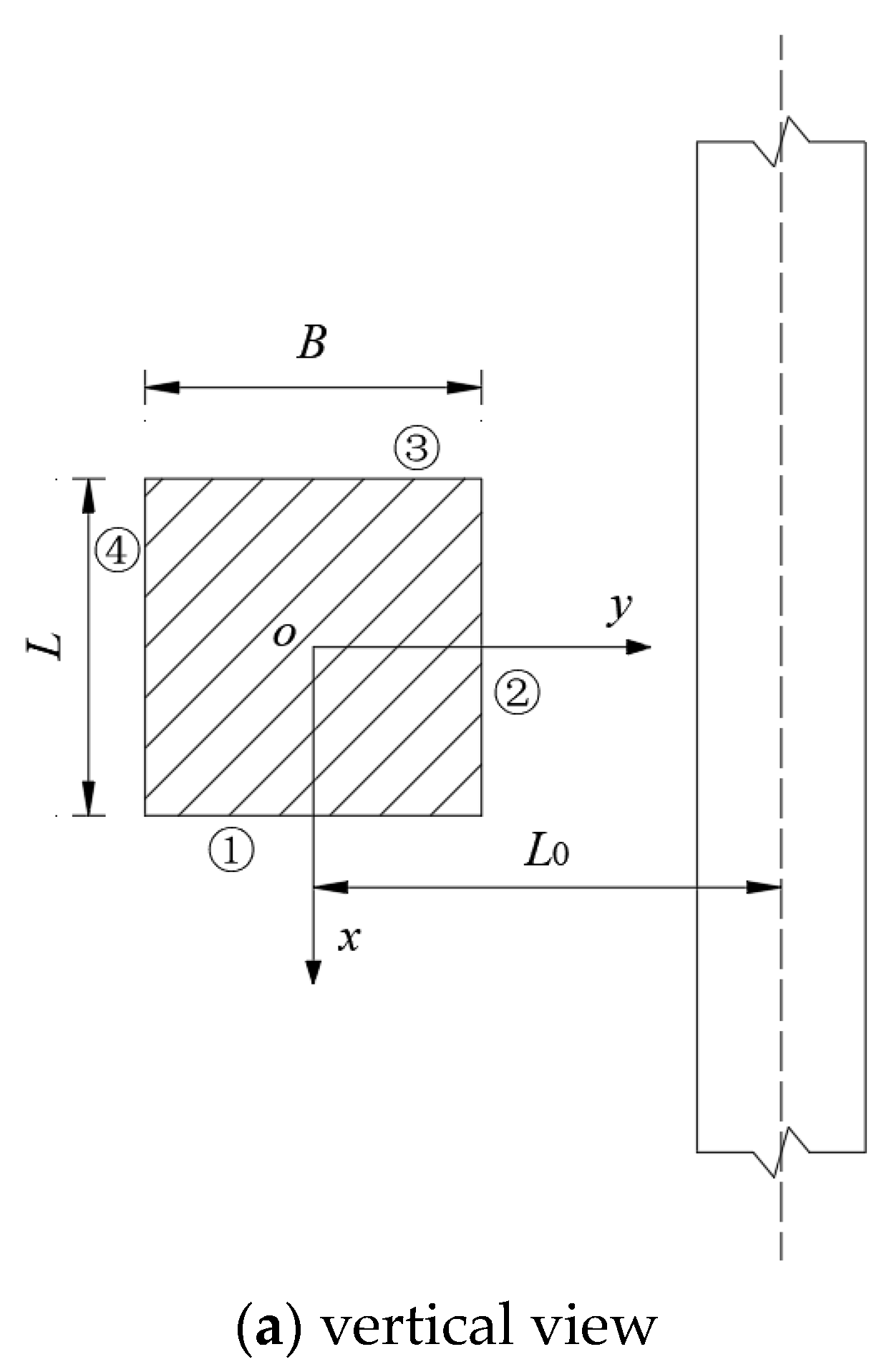
The mechanical calculation model illustrating the impact of foundation pit excavation on adjacent tunnels is depicted in Figure 2. In the initial stage, the additional load at the tunnel position due to the unloading of foundation pit excavation is analyzed by considering the unloading effects of the foundation pit bottom and side walls (①~④), utilizing the Mindlin stress solution [29]. A point (x1, L0, z0) on the tunnel axis experiences a unit force γddξdη from a point (ξ, η) in the rectangular uniform load at the pit bottom, resulting in vertical additional stress () in the tunnel axis direction, as per Equation (1). Similarly, under a unit force K0γτdηdτ from a point (η, τ) in the triangular distributed load on the side wall (①), the vertical additional stress () in the tunnel axis direction is calculated using Equation (2). This process is repeated for side walls (②~④) through the superposition principle to determine the total additional stress on the tunnel induced by the soil unloading from the foundation pit bottom and walls post-excavation. Many scholars have further refined this calculation method by considering various factors to align the additional load calculation more closely with engineering practicality.
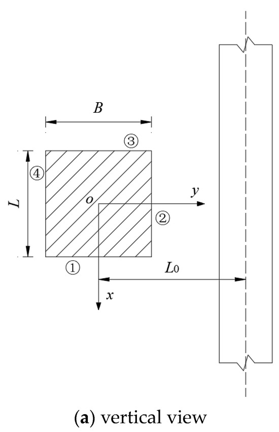

Figure 2.
Mechanical calculation model of the influence of foundation pit excavation on the adjacent tunnel.
In the formula, Ω represents the integral area at the bottom of the pit; Γ represents the integral area on the side wall area (①); and ν represents the Poisson’s ratio of the soil. The calculation methods of R1, R2, T1, and T2 are shown in Equations (3) and (4).
3.1. Base and Foundation Pit Side Wall Unloading
Chen et al. [30], Wang et al. [31], and Zhang et al. [32] have focused on the longitudinal additional stress induced at the existing tunnel position due to unloading at the foundation pit bottom. The analytical formula-derived tunnel uplift value is slightly lower than the field-measured value. This suggests that neglecting the unloading effect of the foundation pit’s side wall impacts the displacement calculation of the tunnel structure.
Jiang et al. [33] analyzed the impact of unloading the pit wall and bottom soil on a tunnel, developing an analytical formula for the tunnel’s longitudinal displacement due to foundation pit excavation. Building on this work, Zhang et al. [34,35] focused on the additional stress from unloading soil around the pit and obtained theoretical solutions for the tunnel displacement and bending moment. While existing studies address unloading effects on the foundation pit, they do not account for the protective role of the retaining structure during excavation, neglecting its impact on additional loads.
3.2. Considering the Influence of the Enclosure Structure
Wei et al. [36,37] suggested that the stress released at the bottom of a pit could be influenced by the side friction resistance generated by the retaining structure. They modified the formula for side friction resistance, as presented in Equation (5), where c represents the cohesion of soil, γ is the unit weight of soil, d is the depth of the foundation pit, H is the depth of the retaining structure of the foundation pit, K0 is the lateral pressure coefficient, and φ is the internal friction angle of soil. Zhou et al. [24] utilized the incremental method [38,39] to analyze the interaction between the supporting structure and the soil. They derived an analytical solution for the vertical displacement of the tunnel, revealing that the impact of foundation pit construction on the tunnel was approximately six times the excavation length.
3.3. Considering the Precipitation Effect
Zhou et al. [25], Zhang et al. [40], Ou et al. [41], and Li [42] investigated the impact of engineering dewatering on the deformation of pre-existing tunnels, as illustrated in Figure 3. They utilized the effective stress principle and seepage theory to determine the extra effective stress induced in the soil due to precipitation, as detailed in Equations (6) and (7). Their findings indicate that precipitation raises the effective stress of the soil, counteracting the additional stress from excavating the foundation pit. The precipitation associated with excavation serves as a beneficial factor in managing the uplift of the existing underlying tunnel.
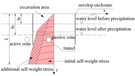
Figure 3.
The influence diagram of engineering dewatering on the additional stress of soil.
The formula is as follows: h1 represents the groundwater level before precipitation, h2 represents the groundwater level after precipitation, and γw represents the weight of water. The hydraulic gradient, denoted as i, is positive when the tunnel is located in the active area and negative otherwise.
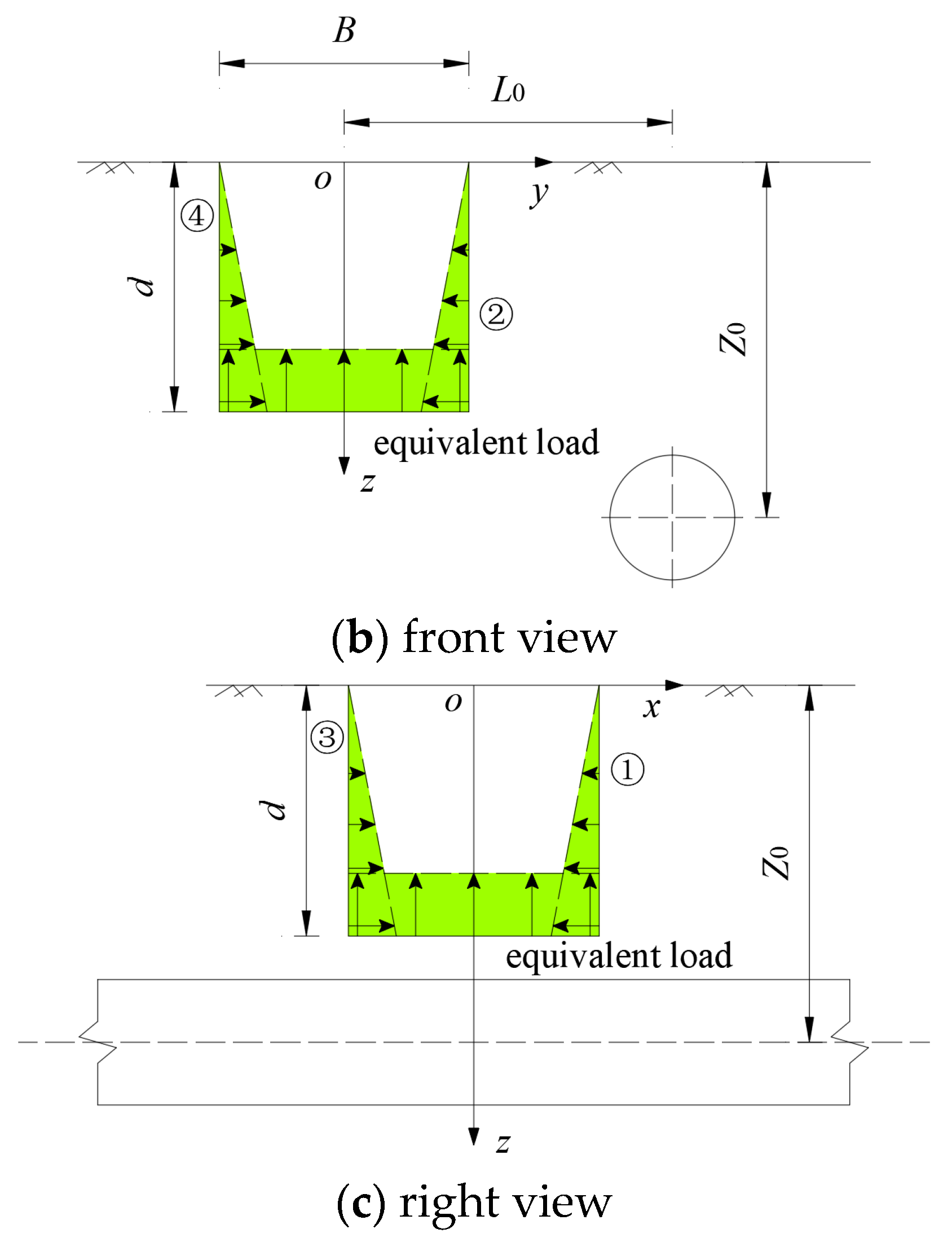
3.4. Considering the Double-Hole Effect
Urban subways are commonly designed with double-line parallel configurations. In cases where the clear distance is limited, a ‘double-hole effect’ may occur. When calculating the total additional stress on tunnel a, it is important to account for the additional stress caused by the contact pressure F between tunnel b and the soil. The additional stress () generated along the axis of tunnel a can be seen in Figure 4.
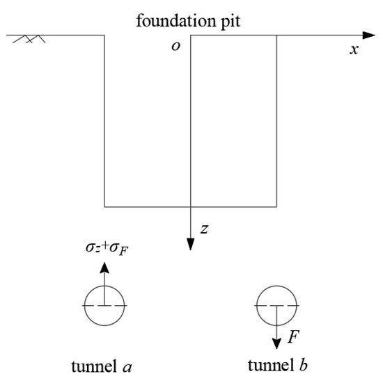
Figure 4.
Calculation diagram of additional stress considering the double-hole effect.
Zhou et al. [43] and Bu et al. [44,45] have provided an analytical solution for the longitudinal additional stress and deformation of a double-hole tunnel’s underlying structure due to the excavation of a foundation pit, considering the ‘double-hole effect’. Equation (8) illustrates the vertical additional stress resulting from the contact pressure between tunnel b (x2, y, z2) and the soil on the axis of tunnel a (x1, y, z1). The findings indicate that the calculated additional stress of a double-hole tunnel caused by foundation pit excavation is lower compared to that of a single-hole tunnel. This is attributed to the fact that the presence of an adjacent double-hole tunnel effectively increases the overall stiffness of the stratum.
The formula represents the contact pressure between tunnel b and the soil, where F is the contact pressure and Lm is the integral range along the y-axis of the tunnel. The longitudinal influence range of the excavation load of the foundation pit is generally between −6L and 6L. H stands for the excavation depth of the foundation pit, with z1 = z − H, z2 = z + H, and z3 = 5z − H. The Poisson’s ratio of soil is represented by u, with u1 = (1 − 2u)/(1 − u), u2 = (3 − 4u)/(1 − u), and u3 = 1/(1 − u). The calculation method for and is detailed in Equations (9) and (10).
3.5. Considering the Residual Stress of Soil and Soil Nonlinearity
Zhang [46], Zhang et al. [47], and Zhang et al. [48] discussed soil behavior as viscoelastic and applied a viscoelastic transformation to the Mindlin elastic half-space stress solution. This approach allowed them to derive an analytical solution for the additional stress near a tunnel induced by excavation unloading in viscoelastic soil.
Liu [49] and Xu et al. [50] introduced the residual unloading stress coefficient α in their research. Equation (11) defines as a function of 0.3 and h, where h represents the thickness of the upper soil at the calculation point and hr is calculated as H/(0.612H + 0.19), with H being the excavation depth of the foundation pit. By considering the residual stress of the soil, Equation (12) calculates the unloading stress, with γ representing the weight of the soil. Finally, utilizing the Mindlin solution, the additional load imposed on the tunnel structure due to the excavation of the foundation pit is determined.
Based on the scholarly research conducted by the aforementioned experts, it has been observed that the calculation method for determining the additional stress at the tunnel axis due to unloading at the bottom of the pit is evidently flawed. While taking into account the unloading of the side walls surrounding the foundation pit helps address these issues, practical engineering factors have not been fully considered. During the construction of foundation pits, excavation and support operations often occur simultaneously, necessitating the evaluation of the enclosure structure’s impact on reducing additional stress. Factors such as project settlement, the presence of double-hole tunnels, and soil characteristics play significant roles in offsetting additional stress and should not be overlooked in the calculation process.
While the calculation method for the additional stress at the tunnel axis caused by the excavation of the foundation pit is relatively comprehensive, it fails to consider the impact of time–space effects. Factors such as the excavation of multiple foundation pits, varying shapes of foundation pits, and different excavation methods should be thoroughly analyzed for their influence on the calculation of additional stress.
4. The Second Stage of the Tunnel Displacement and Internal Force Calculation
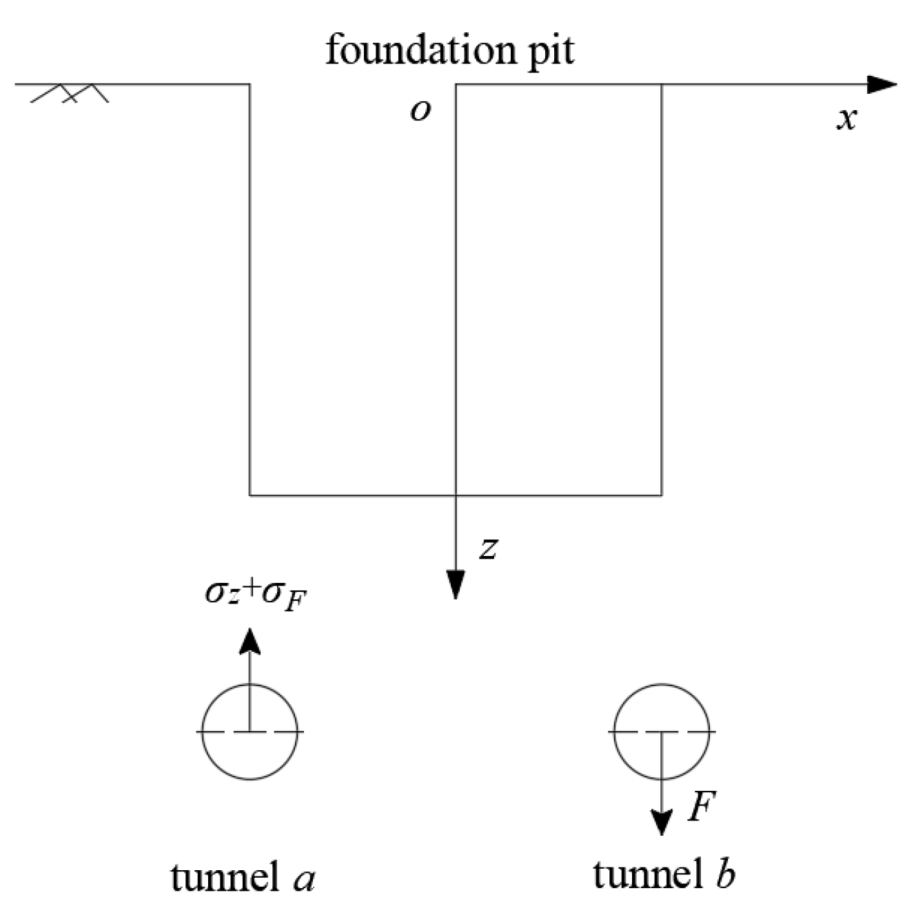
The current predominant interaction model between the foundation and tunnel structures is the Winkler model [51], which is primarily defined by the foundation bed coefficient, k. However, this model may lead to some discrepancies between the calculated results and actual outcomes [52]. To address this issue, some researchers have introduced two-parameter models like the Pasternak model [53] and Vlasov model [54]. Additionally, a three-parameter Kerr model was proposed by another scholar [55]. The interaction model of foundation and tunnel structures is illustrated in Figure 5, with the corresponding equilibrium differential equation presented in Equation (13).

Figure 5.
Interaction model between the foundation and tunnel.
The advantage of the Winkler foundation model is that it has a simple form and is mathematically easy to handle, but it does not consider the continuity and shear action of the soil. The Pasternak and Vlasov foundation models overcome the shortcomings of the Winkler foundation model by introducing shear stiffness parameters and can more accurately simulate soil structure interactions, especially in cases of high soil shear stiffness. The Kerr foundation model adds an upper layer spring on the basis of the Pasternak model to simulate the vertical stress distribution of the soil, thereby more comprehensively reflecting the mechanical behavior of the soil. However, this also means that the calculation of the Kerr model may be more complex.
In the formula, q(x) represents the distributed load on the tunnel, while w(x) represents the deflection of the tunnel. The variables k and c refer to the foundation bed coefficient, and G and 2t denote the shear stiffness of the tunnel.
In the second stage, the vertical displacement and internal force of the tunnel are calculated using an equilibrium differential equation based on the foundation–tunnel interaction model. By considering the boundary conditions, the vertical displacement of the tunnel due to additional stress is determined, and the internal force of the tunnel is calculated using the differential relationship.
The Winkler model is utilized in this study. Initially, the equilibrium differential equation (Equation (14)) is derived. Subsequently, based on the general solution and the boundary conditions, it is determined that at any point ξ along the tunnel structure, the concentrated load is q(ξ)dξ. This load results in the displacement of the point on the tunnel axis, as depicted in Equation (15).
The calculation method of λ is illustrated in Equation (16).
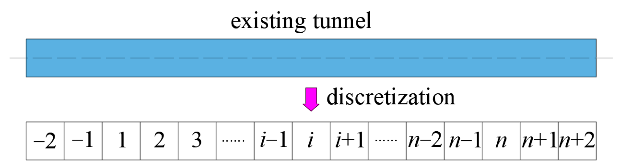
Similar to the Pasternak model, the equilibrium differential equation is first established, as depicted in Equation (17). Subsequently, the numerical solution can be derived using the finite difference method. The tunnel of length L is divided into n units, with each unit having a length of l = L/n. In this case, the tunnel is partitioned into n + 5 units (including four virtual units at both ends), as depicted in Figure 6. The differential results are then obtained, as shown in Equation (18). These results are further transformed into a stiffness matrix, as shown in Equation (19), to solve for the displacement and internal force of the tunnel based on the differential relationship.

Figure 6.
Tunnel discretization schematic diagram.
In the formula, [K1], [K2], and [G0] represent the tunnel bending stiffness matrix, the foundation elastic stiffness matrix, and the foundation shear stiffness matrix, respectively. {w} and {q} denote the vertical displacement and additional stress vector of the tunnel, respectively.
Similar to the Kerr model, this study first establishes the mechanical equilibrium equation (Equation (20)). Subsequently, the solutions for ψ1, ψ2, and ψ3 are obtained using the general solution presented in Equation (21). By combining Equation (20) and Equation (21), the solution for the equation in Equation (22) is derived. Furthermore, the general solution for the shear layer displacement is determined based on its characteristic equation, as shown in Equation (23). The subsequent solution process follows a similar approach to the Winkler model, which will not be further elaborated in this context.
4.1. Considering the Shear Action
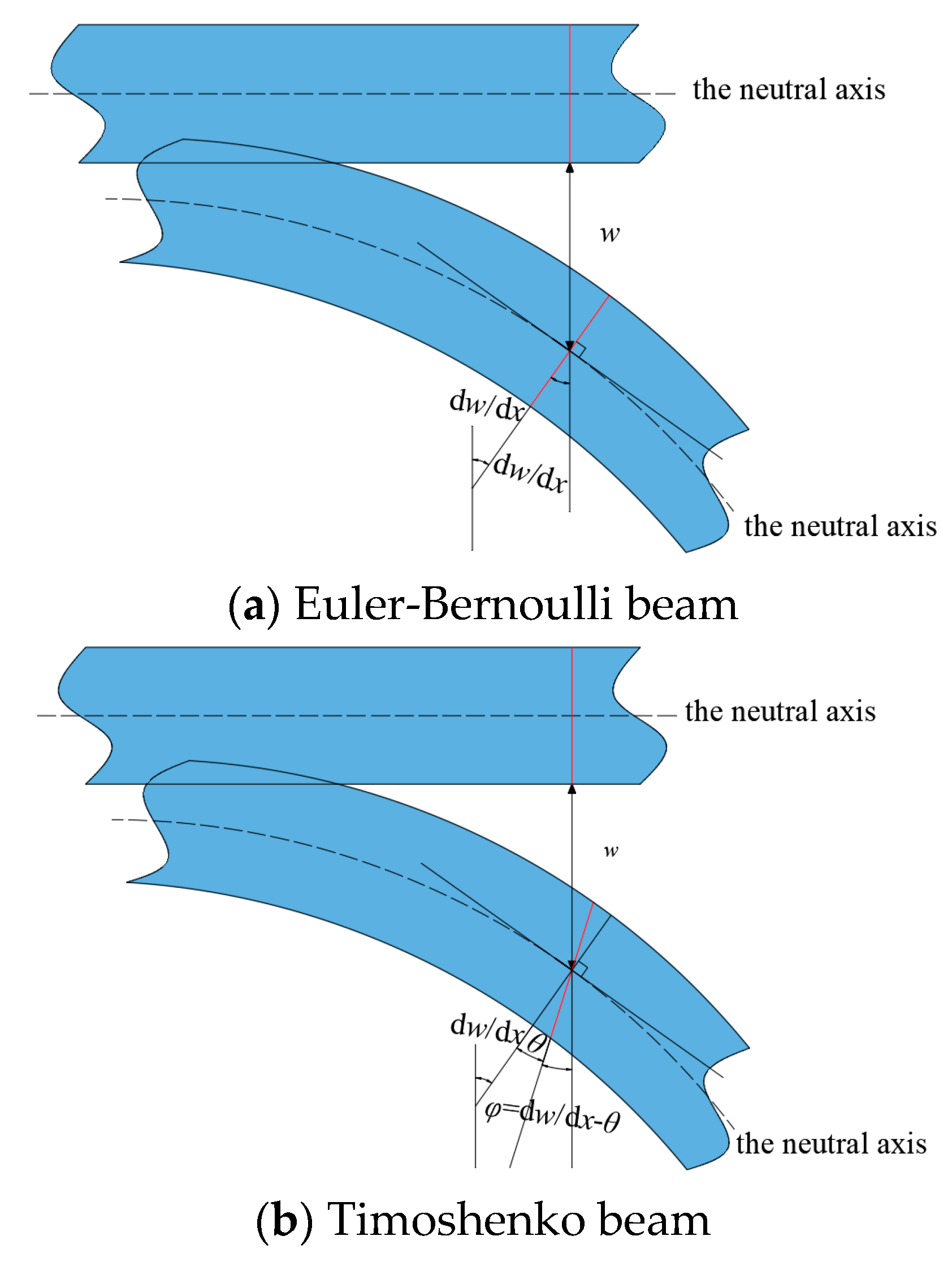
Current theoretical analysis methods often model tunnels as Euler–Bernoulli or elastic straight beams, focusing solely on bending effects and neglecting shear effects. While this approach is suitable for underground tunnels, for subway tunnels with discontinuous integral structures, it is more appropriate to analyze beam deformation under shear using the theory introduced by Timoshenko et al. [56]. Figure 7 illustrates the Euler-Bernoulli beam and Timoshenko beam models.
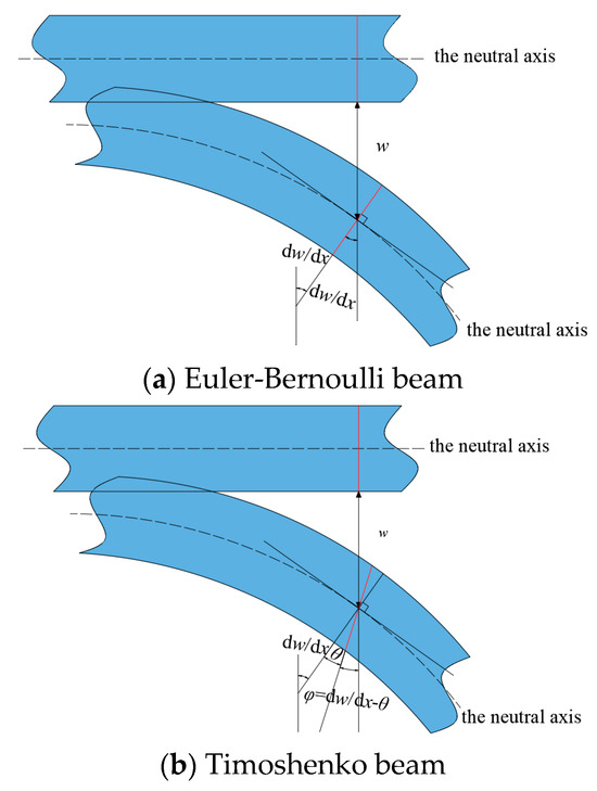
Figure 7.
Tunnel model.
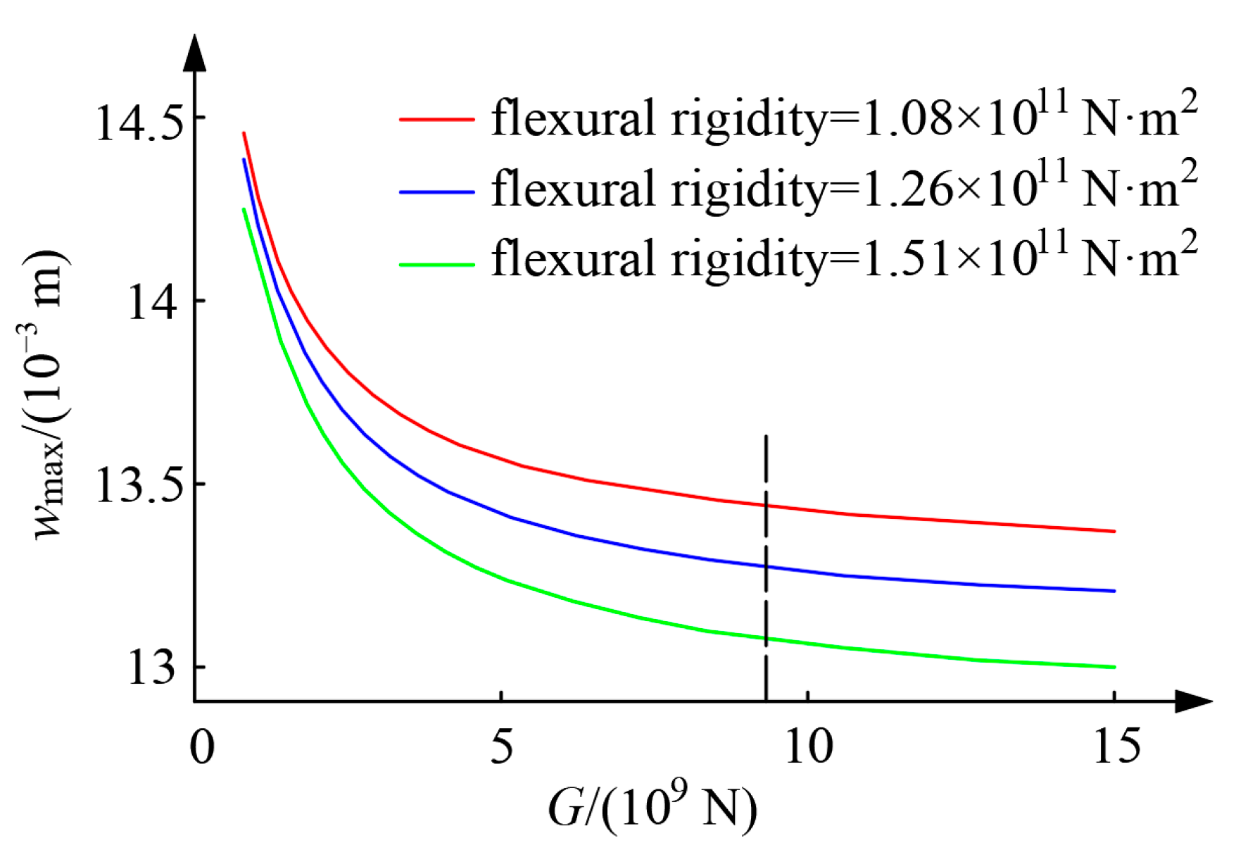
Zong [57] and Liang et al. [58,59] both presented analytical solutions for the mechanical response of the Euler–Bernoulli beam and Timoshenko beam on the Kerr foundation under additional stress. The findings indicate that the displacement and internal force law derived from the Timoshenko beam model is more appropriate. Moreover, as the tunnel shear stiffness G increases, the maximum longitudinal deformation (wmax) gradually decreases. It is observed that when G reaches 9 × 10⁹ N, the longitudinal deformation of the tunnel remains relatively constant, as illustrated in Figure 8.
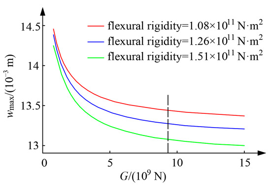
Figure 8.
Vertical displacement of a tunnel under different shear stiffnesses.
Feng et al. [60,61] simplified the tunnel as an infinite Timoshenko beam and analyzed its behavior on a three-parameter Kerr foundation model to obtain an analytical solution for longitudinal deformation. Their findings indicate that tunnel deformation decreases with a higher shear stiffness, while the bending moment and shear force increase. Additionally, an increasing foundation modulus and tunnel depth lead to a reduced tunnel deformation, bending moment, and shear force.
Liu et al. [62,63] simplified the shield tunnel as a Timoshenko beam on a Vlazov foundation to analyze the uplift deformation of the underlying tunnel due to foundation pit excavation. By optimizing the construction parameters of the new foundation pit at Guimiao Road in Shenzhen City based on this model, the study found that the predicted results aligned well with field measurements, validating the accuracy and effectiveness of the approach.
4.2. Considering the Effect of Lateral Soil
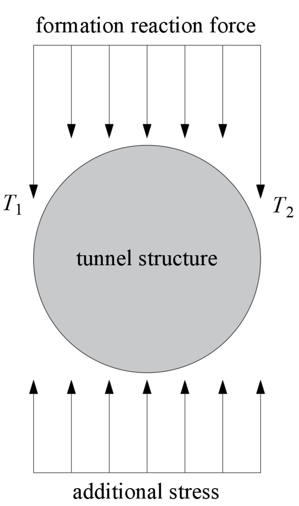
In practical engineering, the additional load from excavating the upper foundation pit not only impacts the tunnel and transfers to the lower foundation but also affects the lateral stratum. The deformation of the lateral soil differs from that of the tunnel, causing pressure on the tunnel. It is hypothesized that the lateral soil forces T1 and T2 on the tunnel are transferred through the shear layer and exerted on both sides of the tunnel [64], as illustrated in Equation (24) and Figure 9.
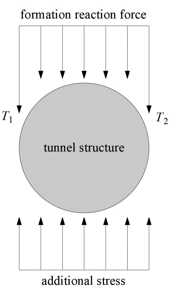
Figure 9.
Tunnel section stress diagram.
In the formula, 2t and k represent the shear stiffness and the foundation bed coefficient, respectively.
Huang et al. [64] derived an analytical solution for the longitudinal deformation of a tunnel beneath lateral soil during the unloading conditions of foundation pit excavation. They recommended reinforcing the soil around the tunnel’s lateral sides to minimize the impact of upper unloading on the tunnel. Tang [65] simplified the tunnel as an infinite Euler–Bernoulli beam on a Vlasov foundation model, accounting for the lateral soil effects and constraints at both tunnel ends. Their analytical solution for vertical tunnel deformation closely matched field monitoring data.
4.3. Considering the Buried Depth Effect of the Tunnel
The foundation bed coefficient is calculated using the formula proposed by Vesić [66] based on long beam load tests on the surface. Attewell et al. [67] later suggested using twice the Vesić subgrade coefficient to estimate the subgrade coefficient of a tunnel with infinite depth, which could lead to an overestimation of soil stiffness. To address this, many scholars have introduced the coefficient η proposed by Yu et al. [68], which takes into account the influence of the tunnel buried depth. This coefficient considers the effect of the tunnel buried depth, as shown in Equations (25) and (26) (where h is the buried depth of the tunnel, D is the outer diameter of the tunnel, Es is the elastic modulus of the foundation soil, ν is the Poisson’s ratio of the foundation soil, and EI is the equivalent bending stiffness of the tunnel).
In light of the impact of tunnel depth, Liang et al. [69] and Xu et al. [70] introduced a revised formula for the foundation bed coefficient and derived a mechanical response solution for tunnels under foundation pit unloading, taking into account the influence of tunnel depth. Building upon the foundation bed coefficient put forth by Cheng et al. [71], Ying et al. [72], and Huang et al. [73], which incorporates the buried depth effect of the tunnel, a calculation method for assessing the response of adjacent existing tunnels due to foundation pit excavation is proposed. The findings indicate that the maximum vertical displacement of the tunnel is significantly influenced by its depth, showing an approximately linear relationship.
4.4. Considering the Non-Uniformity of Soil
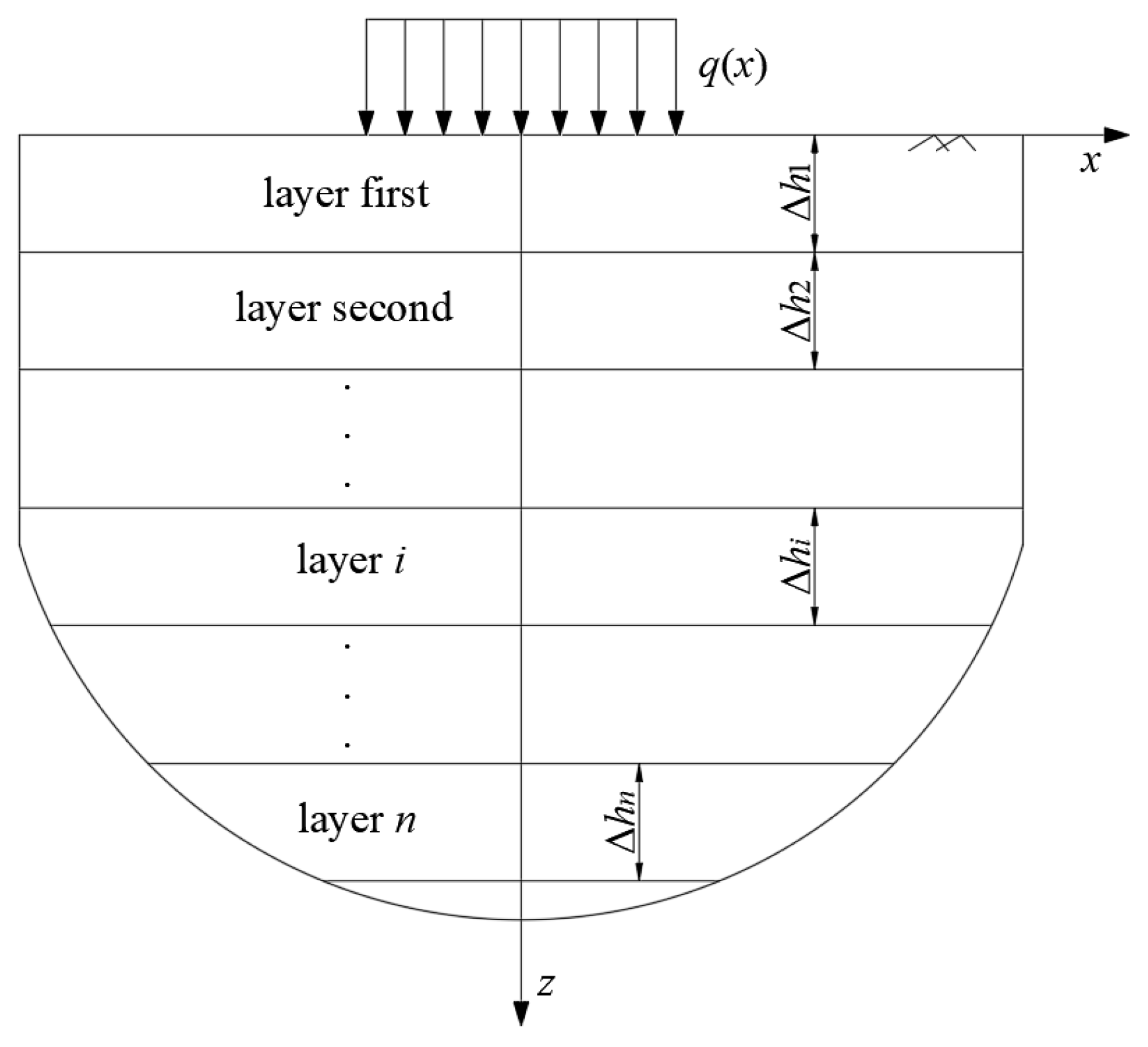
Jiang et al. [74] analyzed the variability of foundation soil by dividing it into n layers based on the Burmister elastic layered theory [75,76,77]. Figure 10 illustrates the action diagram of the axisymmetric vertical load and presents the derived analytical solution for the longitudinal deformation of the tunnel in a layered foundation. The analytical formula accounts for variations in the elastic modulus and Poisson’s ratio with soil stratification while also addressing the issue of excessive stress diffusion in a homogeneous foundation.

Figure 10.
A schematic diagram of an axisymmetric load applied to the surface of a multilayer foundation.
4.5. Considering the Effect of the Segment Joint and the Constraint Effect of the Tunnel End
Previous methods have treated the tunnel as a complete ring without joints or have assumed a fixed stiffness for the joints. In contrast, shield tunnels are constructed by splicing segments with bolts. This construction method assumes the shield tunnel is a continuous structure but may not effectively account for the impact of joints on the tunnel’s longitudinal deformation.
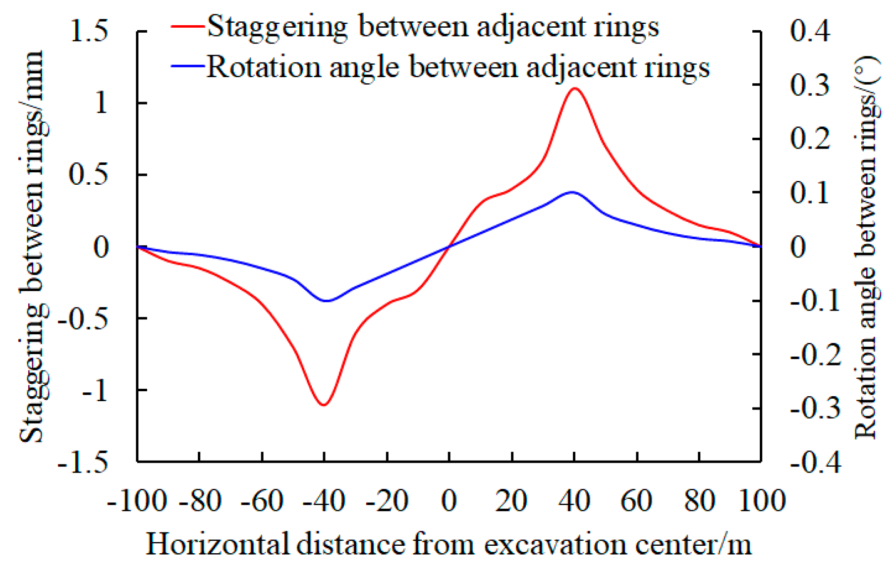
Zhou et al. [78], Wei et al. [79], and Chen et al. [80] investigated the ‘shear dislocation effect’ of shield tunnels, as discussed by Shen et al. [81]. Additionally, Wei et al. [82,83,84], Zhang [85], and Yu [86] proposed that the longitudinal deformation of the tunnel results from the combined effects of shear dislocation and rigid body rotation, as indicated by Wang [87]. They derived formulas for calculating longitudinal deformation, the dislocation amount between rings, the rotation angle between rings, and the shear force between rings induced by foundation pit excavation. The study findings reveal that there is no dislocation deformation at the maximum vertical and horizontal displacement points of the tunnel. The maximum dislocation between rings occurs at the inflection point of the Gaussian curve, as illustrated in Figure 11.
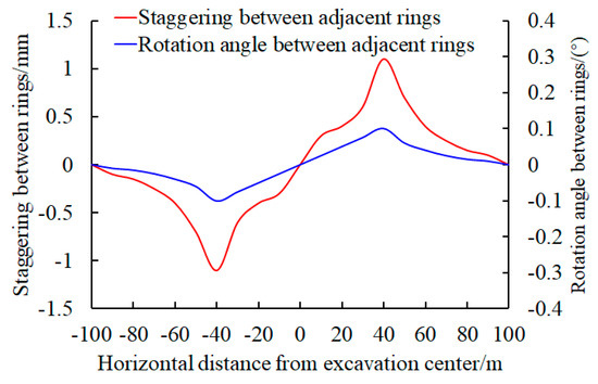
Figure 11.
Dislocation platform and corner of the shield tunnel.
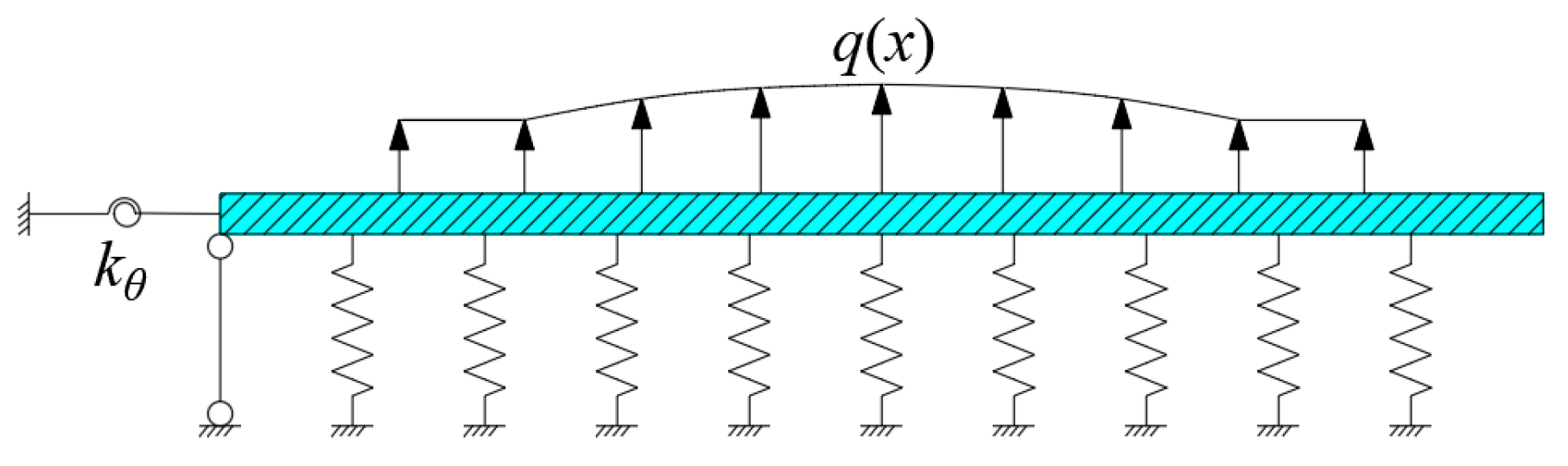
Wang et al. [88] examined the impact of the station (working shaft) constraint on the end of the shield tunnel. The connection node was modeled as a rotating spring with a rotational stiffness of Kθ and a vertical link, as depicted in Figure 12. The analytical solution for the longitudinal response of the adjacent shield tunnel due to the excavation of the foundation pit was derived. This study offers insights for addressing similar challenges within intricate boundary conditions.
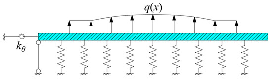
Figure 12.
Mechanical calculation model considering the end constraint effect.
4.6. Considering the Nonlinearity of the Segment Joint and Foundation
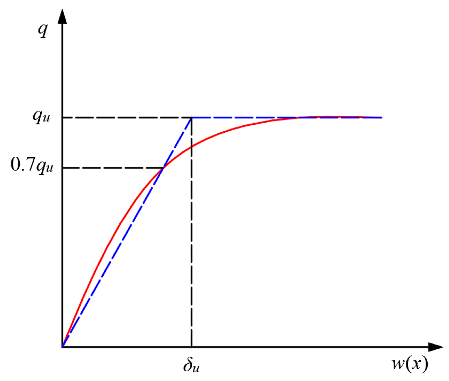
Foundation models such as Winkler, Pasternak, Vlasov, or Kerr all assume that the foundation reaction increases linearly with deformation. However, foundation soil deformation exhibits nonlinear characteristics. As depicted in Figure 13, the foundation reaction force does not increase infinitely with soil displacement but rather approaches a specific critical value. Hence, it is essential to account for the nonlinear deformation characteristics of the foundation when calculating displacements in tunnels under foundation pit unloading.

Figure 13.
Relationship between foundation reaction and displacement.
Zhang et al. [89] investigated the nonlinear variation characteristics of the bending stiffness of the lining joint to solve the analytical solution of the transverse internal force and deformation of tunnels during foundation pit excavation. Kang et al. [90] and Wang et al. [91] developed an analytical solution for the longitudinal deformation of shield tunnels during the excavation and unloading of foundation pits, based on the nonlinear Pasternak foundation model introduced by Liang [92] (refer to Equation (27), where ku represents the ratio of the ultimate foundation reaction force qu to the required foundation soil deformation). The findings suggest that the calculation method utilizing the nonlinear Pasternak foundation model is more dependable.
Based on the research conducted by the aforementioned scholars, it has been determined that the foundation and tunnel model, which takes into account shear action and lateral soil forces, offers a more accurate representation of the actual stress distribution. Additionally, incorporating a calculation model for segment joints enables a more precise analysis of additional displacement and internal forces in shield tunnels. By considering factors such as the tunnel depth, soil non-uniformity, and foundation non-linearity, potential drawbacks of excessive foundation reactions can be effectively mitigated. Moreover, the integration of rotating springs and vertical links presents a novel approach for calculating tunnel displacements under complex boundary conditions.
While the scholars have successfully addressed the issue of displacement and internal force at the tunnel axis resulting from foundation pit excavation, their calculation outcome only provides the overall displacement of the tunnel along the axis direction. It does not offer the displacement of specific positions within the tunnel, such as the vault or inverted arch. This limitation stems from simplifying the tunnel as a beam, and the further analysis of these specific areas could be explored in future research.
5. Engineering Case Verification
A new research project focusing on the transfer channel of the Beijing subway rail transit system is being conducted. The foundation pit for excavation measures 20 m in length, 20 m in width, and 30 m in depth. To support the pit, a combination of a diaphragm wall and steel support is being utilized. The No. 2 subway line is situated 6 m deep and 12 m away from the foundation pit. Figure 14 illustrates the spatial relationship between the foundation pit and the existing tunnel structure, while Table 1 provides the physical and mechanical parameters of the stratum and structure.
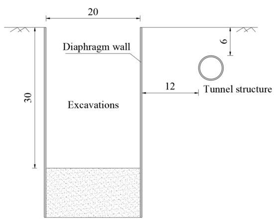
Figure 14.
Location relationship between the foundation pit and tunnel (m).

Table 1.
Physical and mechanical parameters of the strata and structure.
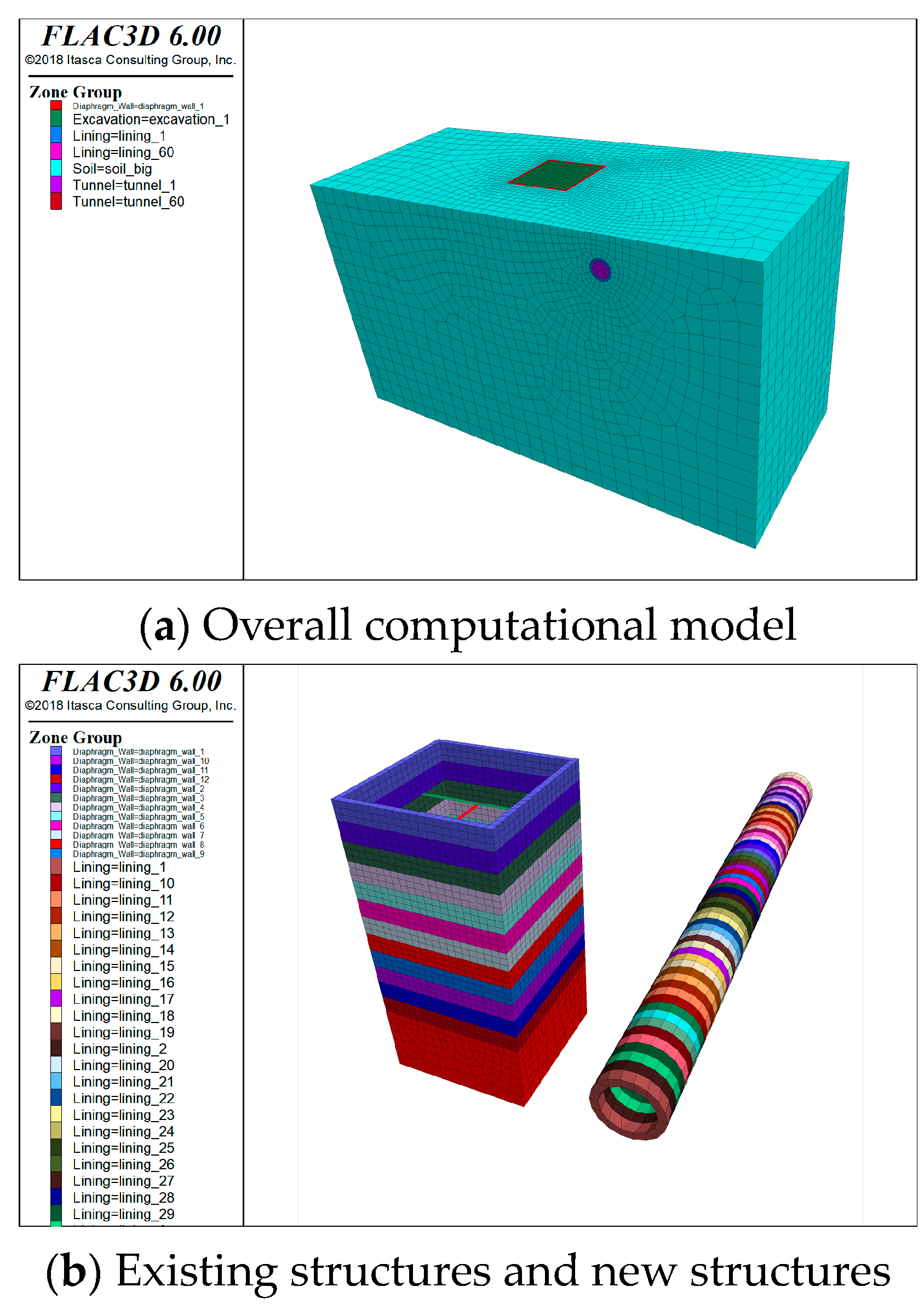
FLAC3D 6.0 finite difference software is utilized to develop a three-dimensional numerical model (Figure 15). The stratum is modeled using the Mohr–Coulomb constitutive model, while the tunnel structure, diaphragm wall, and steel support are modeled using the elastic constitutive model. The top surface of the model is a free surface, and its front, rear, left, right, and bottom surfaces are all constrained to the displacement. The physical and mechanical parameters can be found in Table 1. The construction process of the numerical model consists of two main parts. The first part involves constructing the existing tunnel section and diaphragm wall. Upon completion, displacements are cleared, assuming soil consolidation settlement is complete, leaving only the stress field. This state is considered the initial state for foundation pit construction. The second part involves excavating the foundation pit in 12 layers, each 2.5 m thick, with a total of three steel supports installed at depths of −3 m, −12 m, and −21 m below the surface.

Figure 15.
Three-dimensional numerical model.
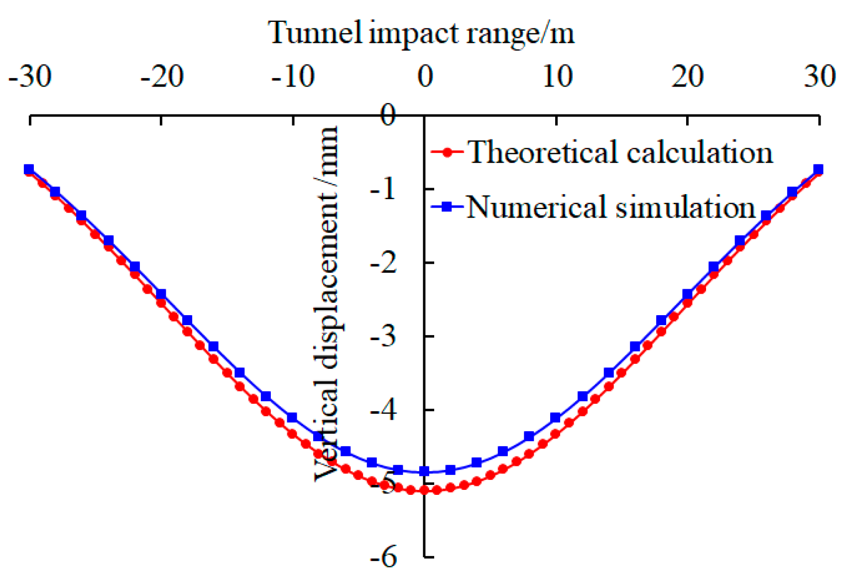
In theoretical calculations, it is assumed that the soil is homogeneous within an elastic half space, and the tunnel structure is an infinitely long homogeneous elastic body, without considering the influence of the tunnel’s existence on the calculation of additional stress in the soil. Engineering factors such as the base unloading, sidewall unloading, and burial depth are considered for the corresponding theoretical analysis. Moreover, the reduction effect caused by the unloading of the foundation and side walls of the foundation pit, as well as the support structure (using a reduction coefficient of 0.75), is considered, along with other relevant parameters detailed in Table 1, assuming a tunnel influence range of 30 m. Comparing the calculated results with the numerical simulation results depicted in Figure 16, it is evident that both patterns are largely consistent. The maximum vertical displacement occurs at the center of the tunnel and gradually decreases as the distance from the center increases. The maximum error observed is only 5.9%, thus validating the rationality of the theoretical calculation.
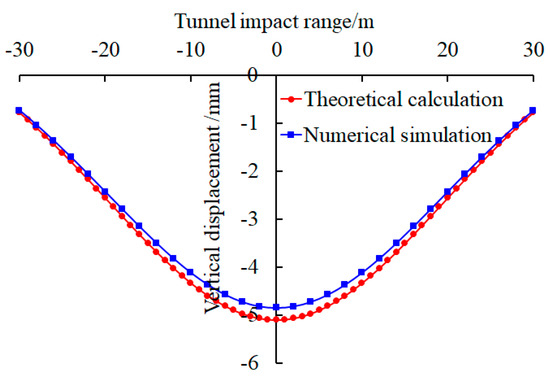
Figure 16.
Comparative analysis of tunnel displacement caused by the excavation of the foundation pit.
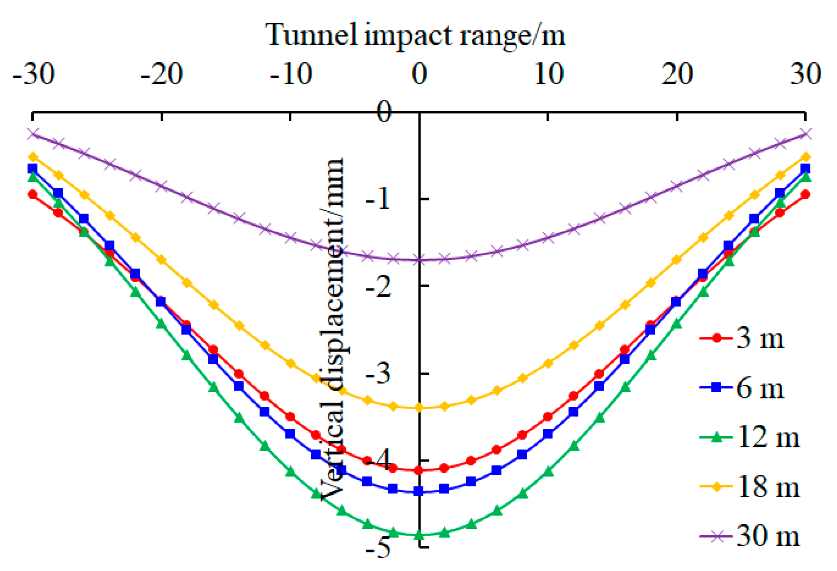
To further investigate the influence of the excavation of the foundation pit on the longitudinal displacement of adjacent tunnels at different distances between the tunnel and foundation pit, numerical simulation methods were used. The depth to 6 m is controlled, with distances of 3, 6, 12, 18, and 30 m, respectively. The remaining parameters are shown in Table 1, and the boundary conditions and construction process of the model are as described earlier. Figure 17 shows the variation curve of the vertical displacement of the tunnel structure caused by the excavation of the foundation pit at different distances. It can be observed that as the distance increases, the vertical displacement of the tunnel structure tends to be smaller on both sides and larger in the middle. Moreover, the maximum vertical displacement of the tunnel structure shows a pattern of first increasing and then decreasing with the increase in the distance.
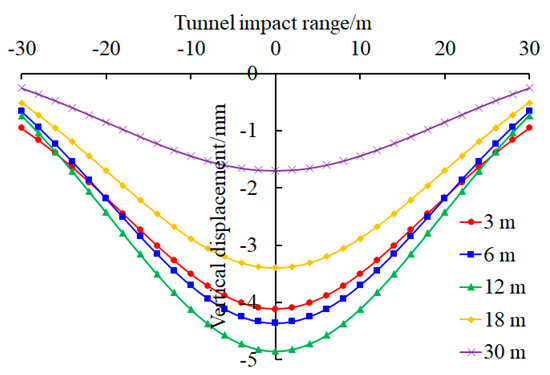
Figure 17.
Vertical displacement of the tunnel structure caused by the excavation of the foundation pit.
There are too many parameters in the paper. In order to express them more clearly, all parameters have been summarized in Table 2.
Table 2.
Parameters Summary.
6. Conclusions
The theoretical analysis method stands out among other research methods for its ability to uncover the mechanical mechanism of foundation pits near existing tunnels. This paper consolidates the research findings of numerous scholars worldwide on this topic, highlighting the strengths and weaknesses of the current theoretical analysis. It offers valuable insights and guidance for future scholars in this field.
(1) In the first stage, the calculation of additional stress takes into account factors such as the unloading model of the foundation pit bottom and side wall, the influence of the retaining structure, the dewatering effect, the double hole effect, the soil material, and residual stress. This approach aligns more closely with engineering practice and yields more accurate results.
(2) In the second stage, the displacement and internal force of the tunnel are calculated using the foundation–tunnel interaction model. The theoretical deduction takes into account various factors such as the shear effect, lateral soil effect, tunnel burial depth effect, soil non-uniformity, tunnel end constraint effect, segment joint dislocation deformation, and nonlinear influence of the tunnel and foundation.
(3) The existing tunnel will have a blocking effect on the surrounding soil. The blocking effect can reduce the soil pressure on the underground continuous wall after the excavation of the foundation pit, which may have an impact on the displacement and internal force of the existing tunnel structure. Further research can be conducted to investigate the impact of this blocking effect on the deformation and internal forces of the tunnel.
(4) Currently, the tunnel structure section is predominantly assumed to be circular. However, in reality, tunnel sections are often non-circular. Further theoretical research on the mechanical response of non-circular section tunnels during foundation pit excavation can be explored. It is recommended to combine the principle of conformal transformation in complex functions to process non-circular cross-sections in order to make the calculation results more in line with engineering practice.
(5) While numerous engineering factors are taken into account during theoretical analysis, the resulting analytical solutions often prove to be overly complex. These solutions can be simplified by expressing them as reduction or amplification factors, which are then combined with field-measured data. This simplified approach can be utilized with the basic formula to streamline calculations.
(6) The validity of theoretical calculations was confirmed through engineering examples and numerical simulations, with a maximum error of only 5.9%, demonstrating good consistency between theoretical calculations and numerical simulations. The two-stage analysis method can be used to analyze the mechanical response of side tunnels caused by the excavation of foundation pits.
Author Contributions
Conceptualization, Z.H.; Methodology, Z.H.; Software, H.M.; Validation, Y.W.; Resources, W.W., Z.L. and B.L.; Data curation, W.W., Z.L. and B.L.; Writing—review & editing, H.M.; Visualization, H.Y.; Supervision, B.L. All authors have read and agreed to the published version of the manuscript.
Funding
The National Key R&D Program of China (2023YFC3806703) and Shijiazhuang Tiedao University Innovation Funding Project (YC202421).
Data Availability Statement
Data that support the findings of this study are available from the corresponding author upon reasonable request.
Acknowledgments
The authors acknowledge the support from Shijiazhuang Tiedao University, Beijing Municipal Construction Group Co., Ltd., and Shijiazhuang Transportation Investment and Development Co., Ltd.
Conflicts of Interest
Authors Wenzheng Wang and Huijun Yang were employed by the company Beijing Municipal Construction Group Co., Ltd. Authors Biao Li and Yonggang Wang were employed by the company Shijiazhuang Transportation Investment & Development Co., Ltd. The remaining authors declare that the research was conducted in the absence of any commercial or financial relationships that could be construed as a potential conflict of interest.
References
- Tang, C.Z.; Peng, X.Q.; Wang, Y. Analysis and treatment of accidents in foundation pit engineering of a municipal tunnel in Wuhan. Chin. J. Geotech. Eng. 2012, 34, 735–738. (In Chinese) [Google Scholar]
- Xiao, X.C.; Yuan, J.R.; Zhu, Y.F. Analysis of the causes of the accident at section C824 of the metro loop line in Singapore (I)—general situation of the project and the accident process. Mod. Tunn. Technol. 2009, 46, 66–72. (In Chinese) [Google Scholar]
- Zhang, H.; Zhang, C.R.; Shi, Z.H.; Huang, M.S.; Wang, H.R.; Zhang, Z.J. Numerical simulation of the influence of foundation pit excavation on tunnel based on IGS small strain model. Chin. J. Geotech. Eng. 2021, 43, 72–75. (In Chinese) [Google Scholar]
- Li, L.; Liu, G.B.; Lu, X.; Ye, J.N.; Huang, Q. Grouting protection test and numerical simulation of subway tunnel excavation adjacent to foundation pit. Chin. J. Undergr. Space Eng. 2021, 17, 387–396. (In Chinese) [Google Scholar]
- Wang, P.C.; Wang, J.; Zhou, S.Q. Numerical simulation analysis of dewatering excavation construction of deep foundation pit across existing tunnel. J. Hefei Univ. Technol. (Nat. Sci.) 2020, 43, 499–506. (In Chinese) [Google Scholar]
- Zuo, Z.B.; Huang, Y.L.; Wu, X.J.; Wang, X. Numerical simulation of the influence of foundation pit construction on the double-track subway tunnel below. J. Beijing Jiaotong Univ. 2019, 43, 50–56. (In Chinese) [Google Scholar]
- Wang, P.C.; Fang, X.; Xu, W.; Wang, J. Numerical simulation of excavation process of existing tunnel foundation pit. J. Hefei Univ. Technol. (Nat. Sci.) 2019, 42, 506–511+540. (In Chinese) [Google Scholar]
- Ma, B.H. Deformation Monitoring and Numerical Simulation of Foundation Pit above Subway Tunnel. Master’s Thesis, Hubei University of Technology, Wuhan, China, 2019. (In Chinese). [Google Scholar]
- Zhang, Z.G.; Xi, X.G.; Wu, L. Numerical simulation and field measurement analysis of the influence of foundation pit excavation on adjacent large-diameter river-crossing tunnels. Tunn. Constr. 2018, 38, 1480–1488. (In Chinese) [Google Scholar]
- Xu, S.F.; Zhou, Q.H.; Zheng, W.H.; Zhu, Y.Q.; Wang, Z. The influence of foundation pit construction on the deformation of adjacent operating tunnels. Chin. J. Geotech. Eng. 2021, 43, 804–812. (In Chinese) [Google Scholar]
- Xu, Z.H.; Zong, L.D.; Shen, J.; Wang, W.D. Deformation analysis of soft soil deep foundation pit adjacent to subway tunnel. Chin. J. Geotech. Eng. 2019, 41, 41–44. (In Chinese) [Google Scholar]
- Ding, Z.; Zhang, X.; Jin, J.K.; Wang, L.Z. Whole process excavation of foundation pit and deformation measurement analysis of adjacent subway tunnel. Rock Soil Mech. 2019, 40, 415–423. (In Chinese) [Google Scholar]
- Chen, R.P.; Liu, S.L.; Meng, F.Y.; Ye, J.N. Centrifugal model test on the influence of foundation pit excavation on the side tunnel in soft clay stratum. Chin. J. Geotech. Eng. 2020, 42, 1132–1138. (In Chinese) [Google Scholar]
- Xu, X.B.; Hu, Q.; Zeng, L.B.; Wang, J.C.; Wang, Z. Model test study on the influence of isolation piles on the side tunnel of foundation pit in dry sand foundation. Chin. J. Rock Mech. Eng. 2020, 39, 3015–3022. (In Chinese) [Google Scholar]
- Chen, R.P.; Ashraf, A.M.; Meng, F.Y. Centrifugal model test on the influence of foundation pit excavation on the side tunnel and the effect of partition wall. Chin. J. Geotech. Eng. 2018, 40, 6–11. (In Chinese) [Google Scholar]
- Liang, F.Y.; Chu, F.; Song, Z.; Li, Y.S. Centrifugal model test on deformation characteristics of deep foundation pit adjacent to subway hub. Rock Soil Mech. 2012, 33, 657–664. (In Chinese) [Google Scholar]
- Rui, R.; Zhai, Y.X.; Xu, Y.Q.; He, Q. Experimental study on the influence of adjacent stratum loss on earth pressure and surface settlement of underground retaining structure. Chin. J. Geotech. Eng. 2021, 43, 644–652. (In Chinese) [Google Scholar]
- Ji, M.J.; Liu, G.B. Displacement prediction method of subway tunnel caused by excavation unloading. J. Tongji Univ. (Nat. Sci.) 2001, 29, 531–535. (In Chinese) [Google Scholar]
- Zhang, J.F.; Wang, J.H.; Wen, S.L. Nonlinear rheology of underlying tunnel uplift caused by soft soil foundation pit. Civ. Constr. Environ. Eng. 2012, 34, 10–15. (In Chinese) [Google Scholar]
- Guo, Y.C.; Li, C.L.; Jin, J.W.; Li, M.Y. Research on the uplift deformation and calculation depth of the underlying tunnel caused by foundation pit excavation. J. Shenyang Jianzhu Univ. (Nat. Sci.) 2019, 35, 875–884. (In Chinese) [Google Scholar]
- Sun, H.S.; Chen, Y.D.; Zhang, J.H.; Kuang, T.S. Analytical investigation of tunnel deformation caused by circular foundation pit excavation. Comput. Geotech. 2019, 106, 193–198. [Google Scholar] [CrossRef]
- Shen, G.Z.; Zhao, H.H.; Zhao, K.; Li, Y. Hermite difference method for tunnel longitudinal displacement caused by deep foundation pit excavation. Chin. J. Undergr. Space Eng. 2020, 16, 841–848. (In Chinese) [Google Scholar]
- Liu, J.W.; Shi, C.H.; Lei, M.F.; Cao, C.Y.; Lin, Y.X. Improved analytical method for evaluating the responses of a shield tunnel to adjacent excavations and its application. Tunn. Undergr. Space Technol. 2020, 98, 103339. [Google Scholar] [CrossRef]
- Zhou, Z.L.; Chen, S.G.; Tu, P.; Zhang, H.S. An analytic study on the deflection of subway tunnel due to adjacent excavation of foundation pit. J. Mod. Transp. 2015, 23, 287–297. [Google Scholar] [CrossRef]
- Zhou, Z.L.; Chen, S.G.; Chen, L.; Tu, P. Simplified theoretical analysis of the influence of foundation pit construction on the uplift deformation of the underlying subway tunnel. Chin. J. Geotech. Eng. 2015, 37, 2224–2234. (In Chinese) [Google Scholar]
- Zhou, J.; Zhou, W.; Chen, B.Q. Calculation of additional stress caused by irregular foundation pit excavation adjacent to subway tunnel. J. Chongqing Jiaotong Univ. (Nat. Sci.) 2017, 36, 17–21++27. (In Chinese) [Google Scholar]
- Zhang, Z.G.; Jiang, K.M.; Wang, Z.W.; Xing, L.; Wei, G.; Ding, Z. Theoretical analysis of longitudinal deformation of existing tunnels induced by foundation pit excavation considering Pasternak foundation model. Tunn. Constr. 2020, 40, 57–67. (In Chinese) [Google Scholar]
- Zhang, B.Q.; Huang, W.; Chen, F.Q.; Wang, Q.Y. Analytical Study on the Transverse Internal Forces of Shield Tunnel Segments due to Adjacent Excavations in Soft Clays. KSCE J. Civ. Eng. 2021, 25, 4842–4855. [Google Scholar] [CrossRef]
- Mindlin, R.D. Force at a point in the interior of a semi-infinite solid. Physics 1936, 7, 195–202. [Google Scholar] [CrossRef]
- Chen, Y.; Li, Y.S. Calculation method of tunnel uplift caused by excavation unloading. Chin. J. Undergr. Space Eng. 2005, 1, 91–94. (In Chinese) [Google Scholar]
- Wang, T.; Li, H.; Xu, R.Q. Deformation analysis of shield tunnel caused by large area loading (unloading) above. Mod. Transp. Technol. 2008, 5, 29–31+57. (In Chinese) [Google Scholar]
- Zhang, Z.G.; Huang, M.S.; Wang, W.D. Influence of adjacent excavation on existing soft soil tunnel. Rock Soil Mech. 2009, 30, 1373–1380. (In Chinese) [Google Scholar]
- Jiang, Z.H.; Zhang, Y.X. Calculation method of influence of foundation pit excavation on longitudinal displacement of adjacent tunnel. Civ. Constr. Environ. Eng. 2013, 35, 7–11+39. (In Chinese) [Google Scholar]
- Zhang, Z.G.; Zhang, M.X.; Wang, W.D. Two-stage analysis of the influence of foundation pit excavation on adjacent subway tunnels. Rock Soil Mech. 2011, 32, 2085–2092. (In Chinese) [Google Scholar]
- Zhang, Z.G.; Huang, M.S.; Wang, W.D. Evaluation of deformation response for adjacent tunnels due to soil unloading in excavation engineering. Tunn. Undergr. Space Technol. 2013, 38, 244–253. [Google Scholar] [CrossRef]
- Wei, G.; Zhao, C.L. Calculation method of additional load of adjacent subway tunnel caused by foundation pit excavation. Chin. J. Rock Mech. Eng. 2016, 35, 3408–3417. (In Chinese) [Google Scholar]
- Wei, G.; Zhao, C.L. Research on displacement calculation of adjacent existing subway tunnels caused by foundation pit excavation. Mod. Tunn. Technol. 2018, 55, 124–132. (In Chinese) [Google Scholar]
- Yang, G.H. Practical calculation method of deep foundation pit supporting structure and its application. Rock Soil Mech. 2004, 25, 1885–1896+1902. (In Chinese) [Google Scholar]
- Feng, S.J.; Chen, X.X.; Gao, G.Y.; Zhang, J.X. Analysis of mechanical behavior of diaphragm wall by iterative incremental method. Rock Soil Mech. 2009, 30, 226–230. (In Chinese) [Google Scholar]
- Zhang, X.M.; Ou, X.F.; Yang, J.S.; Fu, J.Y. Deformation response of an existing tunnel to upper excavation of foundation pit and associated dewatering. Int. J. Geomech. 2017, 17, 04016112. [Google Scholar] [CrossRef]
- Ou, X.F.; Zhang, X.M.; Liu, X.Q.; Yang, J.S.; Liu, J.Q.; Han, X.F. Analytical calculation method for deformation of underlying tunnel caused by foundation pit excavation and dewatering. J. China Railw. Soc. 2019, 41, 147–154. (In Chinese) [Google Scholar]
- Li, H.B. Research on Deformation Mechanism and Control of Subway Tunnel Caused by Shaft Excavation of Large Foundation Pit. Ph.D. Thesis, China University of Mining and Technology, Beijing, China, 2021. (In Chinese). [Google Scholar]
- Zhou, Z.L.; Chen, S.G.; Zhang, H.S.; Tu, P.; Zhang, H. Research on the calculation method of the influence of open-cut unloading on the deformation of the underlying double-hole subway tunnel. J. China Railw. Soc. 2016, 38, 109–117. (In Chinese) [Google Scholar]
- Bu, K.Z.; Zheng, X.C.; Zhang, W.Z.; Guo, J.R.; Shen, X. Calculation method of displacement of existing double-track subway tunnel under composite foundation caused by foundation pit excavation. Tunn. Constr. 2019, 39, 783–794. (In Chinese) [Google Scholar]
- Bu, K.Z.; Zheng, X.C.; Zhang, W.Z.; Guo, J.R.; Shen, X. Study on the calculation of additional load of double-line subway tunnel under composite foundation caused by foundation pit excavation. Railw. Stand. Des. 2019, 63, 126–133. (In Chinese) [Google Scholar]
- Zhang, Q. Vertical Deformation and Its Control of Existing Subway Tunnels under Excavation Unloading. Ph.D. Thesis, Beijing Jiaotong University, Beijing, China, 2012. (In Chinese). [Google Scholar]
- Zhang, J.F.; Chen, J.J.; Wang, J.H.; Zhu, Y.F. Prediction of tunnel displacement induced by adjacent excavation in soft soil. Tunn. Undergr. Space Technol. 2013, 36, 24–33. [Google Scholar] [CrossRef]
- Zhang, S.M.; Feng, T.; Wang, X.Q.; Sun, M.M. Analytical solution of vertical deformation caused by symmetrical excavation of foundation pit. Sci. Technol. Eng. 2016, 16, 263–270. (In Chinese) [Google Scholar]
- Liu, L. Research on the Influence of Foundation Pit Excavation on the Deformation of the Existing Subway Tunnel. Master’s Thesis, Xi’an University of Architecture and Technology, Xi’an, China, 2021. (In Chinese). [Google Scholar]
- Xu, G.Y.; Huang, S.Y. Calculation and analysis of the influence of foundation pit excavation on the deformation of the underlying shield tunnel. J. Chongqing Jiaotong Univ. (Nat. Sci.) 2021, 40, 78–85. (In Chinese) [Google Scholar]
- Winkler, E. Die Lehre von der Elasticitaet und Festigkeit (The Theory of Elasticity and Strength); Dominicus: Prag, Czechoslovakia, 1867. [Google Scholar]
- Kneifati, M.C. Analysis of plates on a Kerr foundation model. J. Eng. Mec. 1985, 111, 1325–1342. [Google Scholar] [CrossRef]
- Pasternak, P.L. On a New Method of Analysis of an Elastic Foundation by Means of Two-Constants. Ph.D. Thesis, Gosudarstvennoe Izdatelstvo Literaturi po Stroitelstvu I Arkhitecture, Moscow, Soviet, 1954. [Google Scholar]
- Vlasov, V.Z. Beams, Plates and Shells on Elastic Foundations; Israel Program for Scientific Translations: Jerusalem, Soviet, 1966. [Google Scholar]
- Kerr, A.D. A study of a new foundation model. Acta Mech. 1965, 1, 135–147. [Google Scholar] [CrossRef]
- Timoshenko, S.P. On the correction for shear of the differential equation for transverse vibration of prismatic bars. Philos. Mag. 1921, 41, 744–746. [Google Scholar] [CrossRef]
- Zong, X. Research on the longitudinal deformation of the underlying tunnel caused by the unloading of foundation pit excavation. Rock Soil Mech. 2016, 37, 571–577+596. (In Chinese) [Google Scholar]
- Liang, R.Z.; Xia, T.D.; Huang, M.S.; Lin, C.G. Simplified analytical method for evaluating the effects of adjacent excavation on shield tunnel considering the shearing effect. Comput. Geotech. 2017, 81, 167–187. [Google Scholar] [CrossRef]
- Liang, R.Z.; Lin, C.G.; Xia, T.D.; Wu, S.M. Analysis of longitudinal deformation of adjacent tunnels due to excavation considering tunnel shear effect. Chin. J. Rock Mech. Eng. 2017, 36, 223–233. (In Chinese) [Google Scholar]
- Feng, G.H.; Xu, C.J.; Zheng, M.W.; Xue, W.J.; Yang, K.F.; Guan, L.X. Research on the longitudinal deformation of the existing tunnel caused by the excavation of the foundation pit under the consideration of shear deformation. J. China Railw. Soc. 2022, 44, 132–141. (In Chinese) [Google Scholar]
- Feng, G.H.; Chen, G.Z.; Zhang, D.; Sun, F.; Wan, P.; Li, Y.J.; Yang, Y.; Xu, C.J. Analytical solution of uplift deformation of existing tunnel induced by excavation of foundation pit. J. Railw. Sci. Eng. 2023, 20, 3908–3917. (In Chinese) [Google Scholar]
- Feng, G.H.; Xu, X.; Hou, S.L.; Fan, R.D.; Yang, K.F.; Guan, L.X.; Xu, C.J. The excavation of foundation pit based on Kerr foundation model causes the deformation of the existing tunnel. J. Shanghai Jiaotong Univ. 2022, 56, 474–485. (In Chinese) [Google Scholar]
- Liu, J.W.; Shi, C.H.; Lei, M.F.; Peng, L.M.; Cao, C.Y.; Lin, Y.X. Analytical calculation method for the influence of foundation pit excavation on the underlying subway tunnel. J. Cent. South Univ. (Sci. Technol.) 2019, 50, 2215–2225. (In Chinese) [Google Scholar]
- Huang, X.; Huang, H.W.; Zhang, D.M. Study on longitudinal deformation of existing shield tunnel caused by excavation unloading. Chin. J. Geotech. Eng. 2012, 34, 1241–1249. (In Chinese) [Google Scholar]
- Tang, X. Simplified calculation method for deformation of existing tunnel caused by foundation pit excavation. Railw. Stand. Des. 2023, 67, 80–87. (In Chinese) [Google Scholar]
- Vesić, A.B. Bending of beams resting on isotropic elastic solid. J. Eng. Mech. Div. 1961, 87, 35–53. [Google Scholar] [CrossRef]
- Attewell, P.B.; Yeates, J.; Selby, A.R. Soil Movements Induced by Tunnelling and Their Effects on Pipelines and Structures; Blackie and Son Ltd.: London, UK, 1986; pp. 128–132. [Google Scholar]
- Yu, J.; Zhang, C.R.; Huang, M.S. Soil–pipe interaction due to tunnelling: Assessment of Winkler modulus for underground pipelines. Comput. Geotech. 2013, 50, 17–28. [Google Scholar] [CrossRef]
- Liang, R.Z.; Wu, W.B.; Yu, F.; Jiang, G.S.; Liu, J.W. Simplified method for evaluating shield tunnel deformation due to adjacent excavation. Tunn. Undergr. Space Technol. 2018, 71, 94–105. [Google Scholar] [CrossRef]
- Xu, R.Q.; Cheng, K.; Ying, H.W.; Lin, C.G.; Liang, R.Z.; Feng, S.Y. Deformation response of tunnel under unloading of foundation pit considering buried depth and shear effect. Rock Soil Mech. 2020, 41, 195–207. (In Chinese) [Google Scholar]
- Cheng, K.; Xu, R.Q.; Ying, H.W.; Liang, R.Z.; Lin, C.G.; Gan, X.L. Simplified algorithm for deformation response of existing tunnel under unloading of overlying foundation pit. Chin. J. Rock Mech. Eng. 2020, 39, 637–648. (In Chinese) [Google Scholar]
- Ying, H.W.; Cheng, K.; Yu, J.L.; Xu, R.Q.; Qiu, Z.J.; Zhan, X.B.; Qin, J.S.; Lou, C.H. Displacement prediction of adjacent shield tunnel induced by foundation pit excavation considering continuous foundation deformation. J. Zhejiang Univ. (Eng. Sci.) 2021, 55, 318–329. (In Chinese) [Google Scholar]
- Huang, M.H.; Hu, Z.G.; Zhou, Z.L.; Zhou, S.H.; Tan, X. Hermite spectrum analysis method for vertical deformation of underlying tunnel caused by foundation pit excavation. J. Saf. Environ. 2024, 24, 488–495. (In Chinese) [Google Scholar]
- Jiang, J.; Qiu, J.T.; Ou, X.D.; Long, T.Y.; Hou, K.W.; Lai, Z.R. Simplified calculation method of deformation of underlying subway tunnel caused by foundation pit excavation. J. Railw. Soc. 2021, 43, 118–126. (In Chinese) [Google Scholar]
- Burmister, D.M. The general theory of stresses and displacements in layered systems. I. J. Appl. Phys. 1945, 16, 89–94. [Google Scholar] [CrossRef]
- Burmister, D.M. The general theory of stresses and displacements in layered soil systems. II. J. Appl. Phys. 1945, 16, 126–127. [Google Scholar] [CrossRef]
- Burmister, D.M. The general theory of stresses and displacements in layered soil systems. III. J. Appl. Phys. 1945, 16, 296–302. [Google Scholar] [CrossRef]
- Zhou, S.H.; He, C.; Xiao, J.H. Energy calculation method for deformation of shield tunnel adjacent to subway caused by foundation pit excavation under staggered platform effect. China Railw. Sci. 2016, 37, 53–60. (In Chinese) [Google Scholar]
- Wei, G.; Yu, G.H.; Zhang, J.; Zhang, Z.G.; Wang, L.Z. Research on calculation of shear dislocation deformation of adjacent shield tunnel caused by foundation pit excavation. J. China Railw. Soc. 2019, 41, 149–155. (In Chinese) [Google Scholar]
- Chen, S.; Wu, H.N.; Chen, R.P.; Shen, S.L.; Liu, Y. Study on the deformation of collinear tunnel caused by long-distance foundation pit excavation above. J. Shanghai Jiaotong Univ. 2021, 55, 698–706. (In Chinese) [Google Scholar]
- Shen, S.L.; Wu, H.N.; Cui, Y.J.; Yin, Z.Y. Long-term settlement behaviour of metro tunnels in the soft deposits of Shanghai. Tunn. Undergr. Space Technol. 2014, 40, 309–323. [Google Scholar] [CrossRef]
- Wei, G.; Hong, W.Q.; Wei, X.J.; Zhang, X.H.; Luo, J.W. Calculation of rotation and dislocation deformation of adjacent shield tunnel caused by foundation pit excavation. Chin. J. Geotech. Eng. 2019, 41, 1251–1259. (In Chinese) [Google Scholar]
- Wei, G.; Zhang, X.H. Calculation of rotation and dislocation deformation of underlying shield tunnel caused by foundation pit excavation. J. Cent. South Univ. (Sci. Technol.) 2019, 50, 2273–2284. (In Chinese) [Google Scholar]
- Wei, G.; Zhao, Y.; Sun, Q. Deformation calculation of shield tunnel with anti-floating anchor caused by foundation pit excavation. J. Cent. South Univ. (Sci. Technol.) 2021, 52, 4158–4167. (In Chinese) [Google Scholar]
- Zhang, X.H. Study on the Influence of Foundation Pit Excavation on the Stress and Deformation of Shield Tunnel Structure. Master’s Thesis, Zhejiang University, Hangzhou, China, 2020. (In Chinese). [Google Scholar]
- Yu, Z.W. Mechanical Model and Application of Adjacent Construction Crossing Existing Shield Tunnel. Ph.D. Thesis, China University of Mining and Technology, Beijing, China, 2021. (In Chinese). [Google Scholar]
- Wang, R.L. Analysis of longitudinal deformation of shield tunnel in Shanghai metro. Undergr. Eng. Tunn. 2009, 1–6+56. (In Chinese) [Google Scholar]
- Wang, Z.X.; Shi, C.H.; Gong, C.J.; Cao, C.Y.; Liu, J.W.; Peng, Z. Analytical method for calculating the influence of excavation of adjacent station (working well) foundation pit on the underlying shield tunnel. Rock Soil Mech. 2022, 43, 2176–2190. (In Chinese) [Google Scholar]
- Zhang, Z.G.; Chen, J.; Zhu, Z.G.; Pan, Y.T.; Wu, Z.T.; Chen, Z.K. Analysis of lateral deformation of adjacent subway tunnel induced by excavation of foundation pit considering nonlinear effect of lining joint. China J. Highw. Transp. 2023. in press (In Chinese). Available online: https://kns.cnki.net/kcms/detail/61.1313.U.20221104.1642.003.html (accessed on 16 June 2024).
- Kang, C.; Ye, C.; Liang, R.Z.; Sun, L.W.; Fang, Y.X.; Wu, W.B. Study on longitudinal nonlinear deformation of underlying shield tunnel induced by foundation pit excavation. Chin. J. Rock Mech. Eng. 2020, 39, 2341–2350. (In Chinese) [Google Scholar]
- Wang, L.X.; Liang, R.Z.; Li, Z.C.; Kang, C.; Xiao, M.Z.; Wu, W.B.; Gao, K.; Guo, Y. Study on uplift deformation of existing shield tunnel induced by excavation of foundation pit. Eng. Mech. 2022, 39, 130–140. (In Chinese) [Google Scholar]
- Liang, R.Z. Simplified analytical method for evaluating the effects of overcrossing tunnelling on existing shield tunnels using the nonlinear Pasternak foundation model. Soils Found. 2019, 59, 1711–1727. [Google Scholar] [CrossRef]


Disclaimer/Publisher’s Note: The statements, opinions and data contained in all publications are solely those of the individual author(s) and contributor(s) and not of MDPI and/or the editor(s). MDPI and/or the editor(s) disclaim responsibility for any injury to people or property resulting from any ideas, methods, instructions or products referred to in the content. |
© 2024 by the authors. Licensee MDPI, Basel, Switzerland. This article is an open access article distributed under the terms and conditions of the Creative Commons Attribution (CC BY) license (https://creativecommons.org/licenses/by/4.0/).