Article

Experimental Study on the Mechanical Properties of a New Type of Prefabricated Steel–Concrete-Composite Energy-Dissipation Shear-Wall System

1
Guangdong Power Grid Co., Ltd., Guangzhou 510180, China
2
Power Grid Planning Research Center of Guangdong Power Grid Co., Ltd., Guangzhou 510220, China
3
Shantou Power Supply Bureau of Guangdong Power Grid Co., Ltd., Shantou 515031, China
4
School of Civil and Transportation Engineering, Guangzhou University, Guangzhou 510006, China
*
Author to whom correspondence should be addressed.
Buildings 2025, 15(6), 941; https://doi.org/10.3390/buildings15060941
Submission received: 25 February 2025 / Revised: 10 March 2025 / Accepted: 13 March 2025 / Published: 17 March 2025
(This article belongs to the Section Building Structures)

Abstract

:
In order to enhance the energy-dissipation capacity and comprehensive seismic mechanical behavior of prefabricated steel–concrete-composite shear-wall structures, a new prefabricated composite energy-dissipation shear-wall system is proposed, which is composed of a shear-wall module and an energy-dissipation module connected by high-strength bolts. Four sets of comparative mechanical performance testing were conducted on the proposed composite energy-dissipation shear wall, including one set of traditional prefabricated composite shear-wall specimens (specimen TPCW) and three sets of composite energy-dissipation shear-wall specimens designed with different energy-dissipation modules (specimens PCEDW-A, PCEDW-B, and PCEDW-C). The results indicate that the proposed specimens PCEDW-A and PCEDW-B have a good bearing capacity and energy-dissipation characteristics, in which the number and range of concrete crack developments are lower than those of the traditional TPCW specimen under the same loading drift ratio condition. Compared with specimen TPCW, the ultimate bearing capacities of specimens PCEDW-A and PCEDW-B are increased by 13.76% and 17.15%, respectively. However, the equivalent damping ratio of specimen PCEDW-A is much higher than that of specimen PCEDW-B, and the former is nearly four times higher than the latter at the drift ratio of 1/100. Taking into account the load-bearing capacity and energy-dissipation characteristics, using a horizontal diamond-shaped perforated metal damper, specimen PCEDW-A exhibits the optimal mechanical behavior.

1. Introduction

Nowadays, China’s natural resources such as land, water, and energy are constantly scarce. At the same time, multiple factors such as the upgrading of national environmental protection requirements, increasingly strict building quality requirements, rising labor costs, and decreasing scale of construction workers have posed enormous challenges to the traditional construction industry, which is characterized by low labor prices, severe consumption of natural resources, and weak environmental awareness. The traditional construction industry has had to shift from being labor intensive to technology intensive and management intensive. The green building and building assembly industrialization model, characterized by standardized component design, modular factory production, on-site prefabricated construction, and remote information management, has emerged [1,2]. The steel–concrete-composite shear wall fully utilizes the advantages of both steel and concrete materials, and has superior performance compared to ordinary reinforced-concrete shear walls, such as a high bearing capacity, good seismic performance, and high lateral stiffness [3,4]. Dai et al. [5] proposed a new type of ductile low-shear wall with multiple-stepped horizontal-semi-through-seam shear walls along the diagonal direction of the wall panel, a new type of ductile low-shear wall with a friction-control device, and a high-strength low-shear wall with a vertical-seam-channel steel fiber, through research. Ye et al. [6] formed a new type of dual-function slotted shear wall by designing connection keys at the through-joint position, which increased the initial first stiffness of the shear wall by about 2.5 times compared to the through-joint wall, and reduced the yield second to lateral stiffness to 1–2% of the initial stiffness. Guo et al. [7] proposed anti-buckling steel-plate shear walls and proposed the equivalent model BSM for anti-buckling steel-plate walls. Lin et al. [8] proposed a steel-truss coupled-beam coupled shear-wall structure system. Wei et al. [9,10] studied a hysteresis model and mechanical mechanism of a novel locally connected buckling-restrained steel-plate shear wall. Jin et al. [11] conducted experimental and numerical studies on the stability of steel-plate shear walls (SPSWs) with buckling constraints and inclined slots, and found that the external concrete slab constraint provided a stable energy-dissipation capacity for SPSWs. Wang et al. [12] studied the seismic performance of a self-restrained steel-plate shear-wall (SBR-SPSW) structural system, including shear strength, hysteresis behavior, and energy-dissipation characteristics.
However, the excessive self-weight and lateral stiffness of ordinary concrete shear walls also make them absorb more seismic forces and bear greater seismic loads under earthquake action, often resulting in brittle failure due to insufficient ductility in previous earthquakes. Energy-absorbing shear walls have broken through the traditional seismic resistance method that relies on the ductility of the structure itself to resist earthquakes. They propose to improve the seismic performance of the structure by setting up energy-absorbing devices and jointly sharing the seismic action with the structural components, achieving the goal of “overcoming rigidity with flexibility”. Dong et al. [13] proposed a shear-wall structure form with energy dissipation concealed supports and embedded steel-plate energy-dissipation keys, and explored the seismic performance of shear walls such as stiffness, bearing capacity, ductility, and energy-dissipation capacity. Wu et al. [14] proposed a composite-coupled shear wall with a shear-mechanism energy-dissipation end-plate bolt connection form. Dong et al. [15] proposed a new SMA energy-dissipation coupled-beam shear-wall structure. Sun et al. [16] proposed a sandwich-rubber-pad energy-dissipation low-shear wall by disconnecting the middle of the shear wall along the transverse direction and connecting the upper and lower wall limbs with a sandwich rubber pad. Li et al. [17] proposed a steel-tube–concrete energy-dissipation shear wall by disconnecting the shear wall along the transverse direction and connecting the upper and lower wall limbs with steel-tube–concrete columns. There are also more studies focusing on the mechanical performance of new prefabricated composite shear-wall structures, and fruitful research results have been achieved [18,19,20,21,22,23].
Although prefabricated buildings are currently in high demand, their research and application are still in a transitional stage, and many key technologies need further research and exploration, such as the development of new components and systems for prefabricated buildings, and the research on new energy dissipation and seismic reduction technologies for prefabricated steel–concrete-composite structures [24,25]. It can be seen that scholars at home and abroad have proposed various forms of energy-absorbing shear walls and conducted in-depth research, confirming the superiority of energy-absorbing shear-wall structures in seismic performance such as ductile deformation and hysteresis energy dissipation. However, most existing research has focused on the seismic performance of ordinary reinforced-concrete energy-dissipation shear walls, and the literature is still limited in terms of the seismic performance of prefabricated composite energy-dissipation shear-wall structures. Therefore, a new type of prefabricated steel–concrete-composite energy-dissipation shear-wall structural system is proposed, which has better load-bearing and energy-dissipation characteristics by introducing energy-dissipation and seismic-reduction technology. To verify the seismic behavior of the proposed new composite energy-dissipation shear wall, a comparative study was conducted on the mechanical properties of traditional shear walls and new shear walls with different energy-dissipation combinations, so as to provide theoretical and technical support for potential engineering applications.

2. Experimental Plan Design
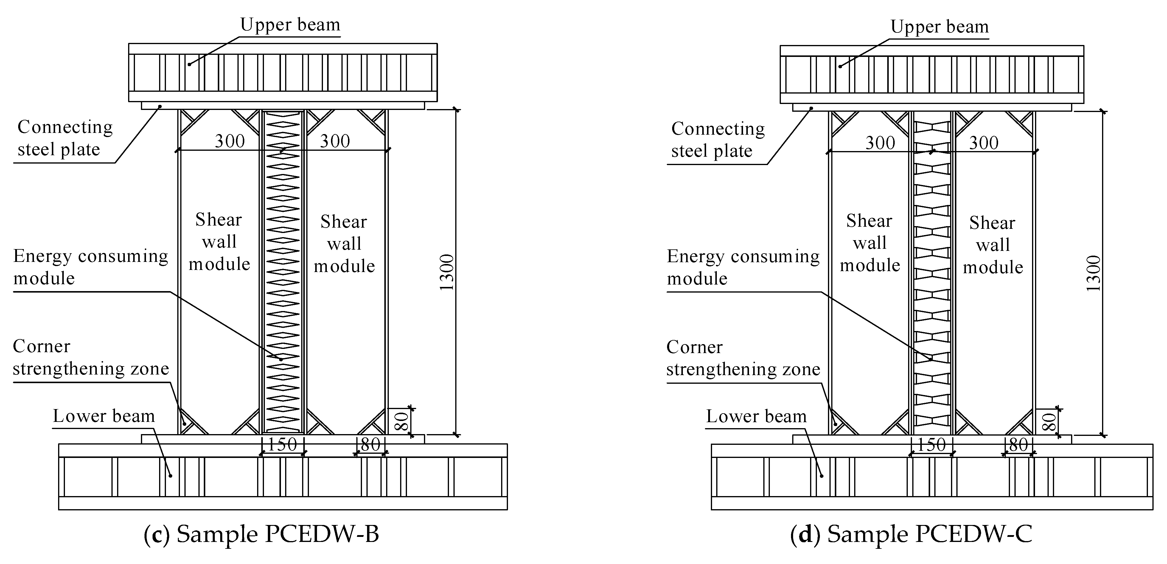
2.1. Sample Design

To compare the mechanical behavior of different assembled composite energy-dissipation shear walls, four sets of energy-dissipation shear-wall test samples were designed and produced, including 1 set of ordinary assembled composite shear-wall samples as a contrast model and 3 groups of samples of prefabricated composite energy-dissipation shear walls with different energy-dissipation construction methods. The main purpose of selecting these four test samples was to verify the superiority of the proposed new-combination energy-dissipation shear wall. In addition, there have been no relevant reports on this new type of composite energy-absorbing shear wall in the literature, which is also easy to implement in practical engineering applications. The test sample was connected to the upper and lower loading beams through high-strength bolts, and the size of the upper loading beam was 220 mm × 1100 mm × 210 mm. The dimensions of the lower loading beam were 250 mm × 1600 mm × 450 mm, and all loading beams were made of Q345 steel. The specific parameter design of the experimental sample was as follows:
Testing sample of the traditional prefabricated composite energy-dissipation shear walls (sample TPCW): As is shown in Figure 1a, two prefabricated steel-plate composite shear-wall modules were assembled on site using M20 high-strength bolts. The dimensions of the shear-wall modules were 1300 mm (height) × 300 mm (width) × 100 mm (thickness). The shear-wall module contained a 3 mm thick inner steel plate made of Q235 steel. The shear-wall module was wrapped with concrete slabs on both sides, with dimensions of 1235 mm × 279 mm × 48.5 mm and a concrete strength grade of C30. HPB300-grade steel bars were used, with a diameter of 8 mm and a spacing of 100 mm between vertically and horizontally distributed bars. Steel-plate connectors around the shear-wall module were designed to assemble and connect with other modules through high-strength bolts. In addition, to prevent the phenomenon of premature failure of the corner concrete during the loading process of the shear-wall modules, steel reinforcement zones were designed at the corners of the shear-wall modules, and the hidden steel plates in this area were thickened and reinforced ribs were added.
Testing sample A of the prefabricated composite energy-dissipation shear wall (sample PCEDW-A): As is shown in Figure 1b, this consists of two shear-wall modules and one energy-dissipation module, which were assembled on-site using high-strength bolts. The shear-wall module design was the same as for sample TPCW. The energy-dissipation module adopted a transverse steel-plate metal damper with diamond holes. The transverse plate was made of Q235 material, with a thickness of 2 mm, length of 134 mm, and width of 100 mm. The spacing between the transverse plates was 21 mm. A total of 51 metal plates were designed for the metal damper of sample PCEDW-A, and the two ends of the transverse plates were welded to the steel connection plate.
Testing sample B of the prefabricated composite energy-dissipation shear wall (sample PCEDW-B): As is shown in Figure 1c, this was also composed of two shear-wall modules and one energy-dissipation module, which were assembled. The shear-wall module and the energy-dissipation module were connected by high-strength bolts through steel plates. Unlike for sample PCEDW-A, the metal damper was designed using vertical steel plates with diamond-shaped holes. The vertical plates were 2 mm thick, 1219 mm long, and 134 mm wide, with a spacing of 47 mm between them. A total of three metal plates were used for the metal damper of sample PCEDW-B. There are some factors that need to be considered in the design of energy-consuming modules, such as the following: the connection with the surrounding components needs to be firm, and there should be no relative deformation under external forces; the design and processing of energy consumption models need to ensure sufficient accuracy.
Testing sample C of the prefabricated composite energy-dissipation shear wall (sample PCEDW-C): As is shown in Figure 1d, this was also composed of two shear-wall modules and one energy-dissipation module, which were assembled. Unlike for sample PCEDW-A and sample PCEDW-B, the metal damper used double-cone energy dissipators with a diameter of 40 mm at the end and 10 mm in the middle, and a length of 134 mm. The axial distance between the double cones was 80 mm, and a total of 15 double-cone energy dissipators were used.

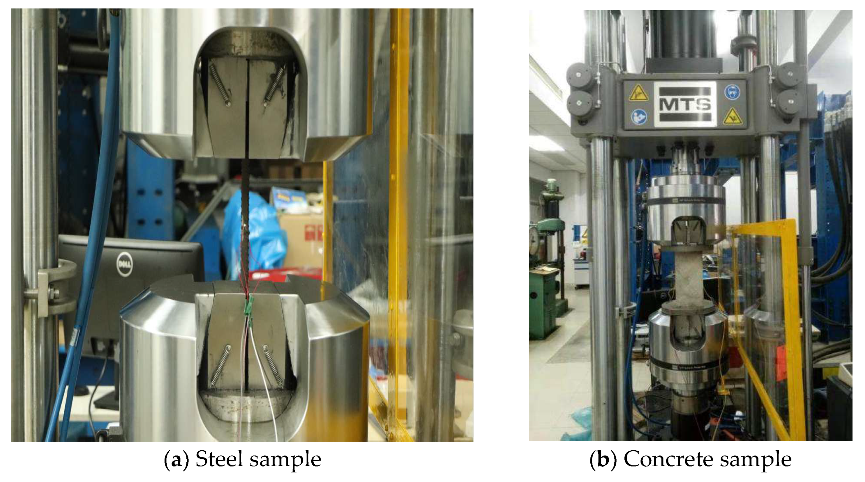
2.2. Material Performance Testing
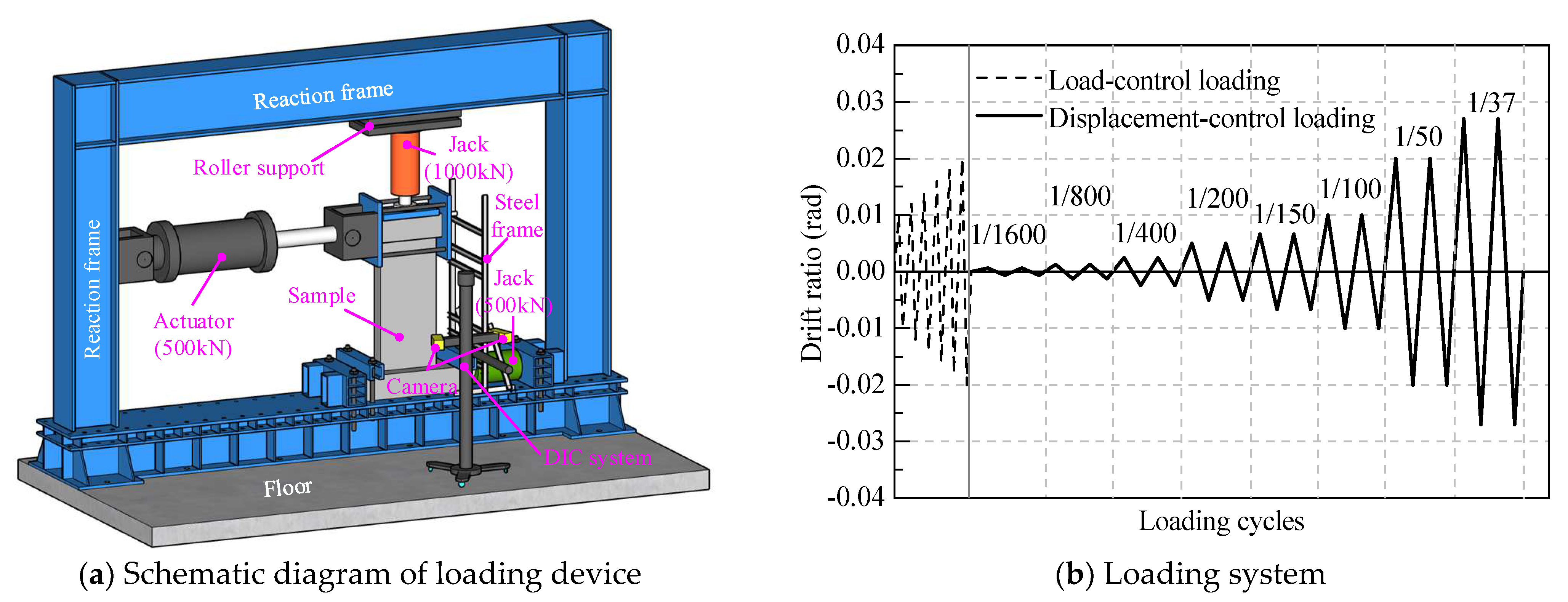
The steel specimens were prepared according to the relevant provisions of “Sampling locations and specimen preparation for mechanical property tests of steel and steel products”, with three specimens per group. The loading method and data processing were determined by “Tensile Testing of Metallic Materials Part 1: Room Temperature Test Method”. The tensile strain was determined by attaching strain gauges to the surface of the steel specimen. The steel tensile test was conducted using the MTS 311.31 universal testing machine, as shown in Figure 2a. The concrete used for the test piece was C30-grade commercial concrete, with fine aggregate and coarse aggregate. To ensure high fluidity of the concrete, the designed slump was 160–180 mm. During the pouring of concrete, three concrete specimens were made and cured under the same conditions as the specimens. The MTS 311.31 universal testing machine was also used for the compression test of concrete test blocks, as shown in Figure 2b. The loading method was in accordance with the “Standard Test Method for Physical and Mechanical Properties of Concrete”. The mechanical performance parameters of steel and concrete are shown in Table 1 and Table 2.

2.3. Loading Design

The loading device is shown in Figure 3a. The bottom beam was fixed to the reaction frame base with screws, and a horizontal 500 kN jack was used to press the bottom beam to prevent slippage during the loading process. A 1000 kN vertical jack was installed on the top beam of the reaction frame to apply vertical loads. A roller was set between the vertical jack and the top beam of the reaction frame to ensure the free sliding of the specimen during horizontal reciprocating loading. An MTS 244.41 hydraulic actuator provided the horizontal reciprocating load, and the actuator was connected to the specimen through a beam-holding device composed of a “clamp screw”. The push-out direction is defined as a positive direction, and the pull-back direction is defined as a negative direction.
Before loading the test, final tightening was performed on the high-strength bolts to ensure sufficient connection strength. The two hoists, that vertically lift the actuator to avoid the safety hazard of hoist breakage caused by the settlement and lifting of the actuator during the reciprocating loading process of the specimen, were loosened before carrying out the test loading work. Firstly, the oil pump was used to control the oil intake of the vertical jack, ensuring that the axial load of the jack remained constant at 120.6 kN (corresponding to an axial compression ratio of 0.05 for the shear wall). Then, a horizontal load was applied according to the loading system shown in Figure 3b. Initially, the force-control method was used to apply horizontal loads to verify the rationality of the connections between the loading components. Subsequently, the displacement-control method was used to apply horizontal reciprocating loads, with each loading stage cycling twice until the displacement angle reached 1/37 rad, or when the horizontal shear force dropped to 85% of the peak shear force, indicating the end of loading.

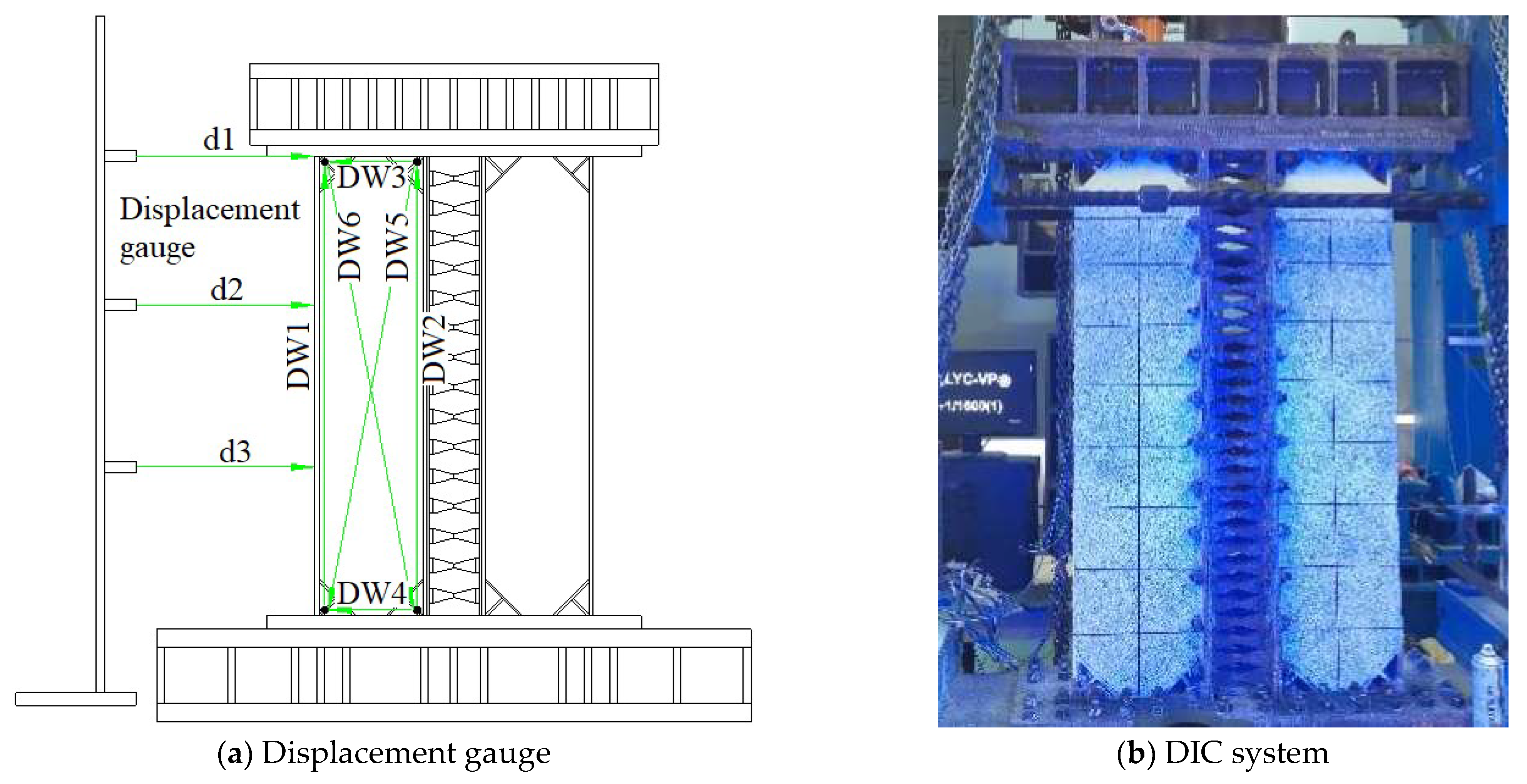
2.4. Data Collection

Two sets of data acquisition systems were used for synchronous data monitoring in the experiment, namely the traditional acquisition instrument of the MTS FlexDAC-20 data acquisition system, and the DIC (Digital Image Correlation) three-dimensional digital-image-related data acquisition system. The MTS FlexDAC-20 system mainly collects displacement, strain, and vertical-jack-load data from various measuring points, in order to obtain information on the lateral displacement, shear deformation, bending deformation of the wall, and strain of the steel bars. As is shown in Figure 4a, displacement sensors d1~d3 were spring-type displacement sensors used to test the lateral displacement of the wall body. The displacement sensors DW1~DW6 were articulated displacement sensors used to test the relative deformation between two measuring points on the wall.
Given that traditional collection methods can only cover a limited number of measurement points and cannot obtain full-field data, and the crack propagation process of the specimen can only be carried out using the “naked-eye-recognition freehand drawing” method, the collection needs to be close to the loaded specimen, which poses a safety hazard. Moreover, small cracks similar to hair strands are difficult to detect, and the data collection results rely heavily on experience and professional skills. To this end, a three-dimensional digital image correlation (DIC) data acquisition system was introduced, which was mainly used to monitor the detailed development process of surface cracks of concrete specimens during loading, and could obtain more accurate full-field data, as shown in Figure 4b.

3. Analysis of Testing Results

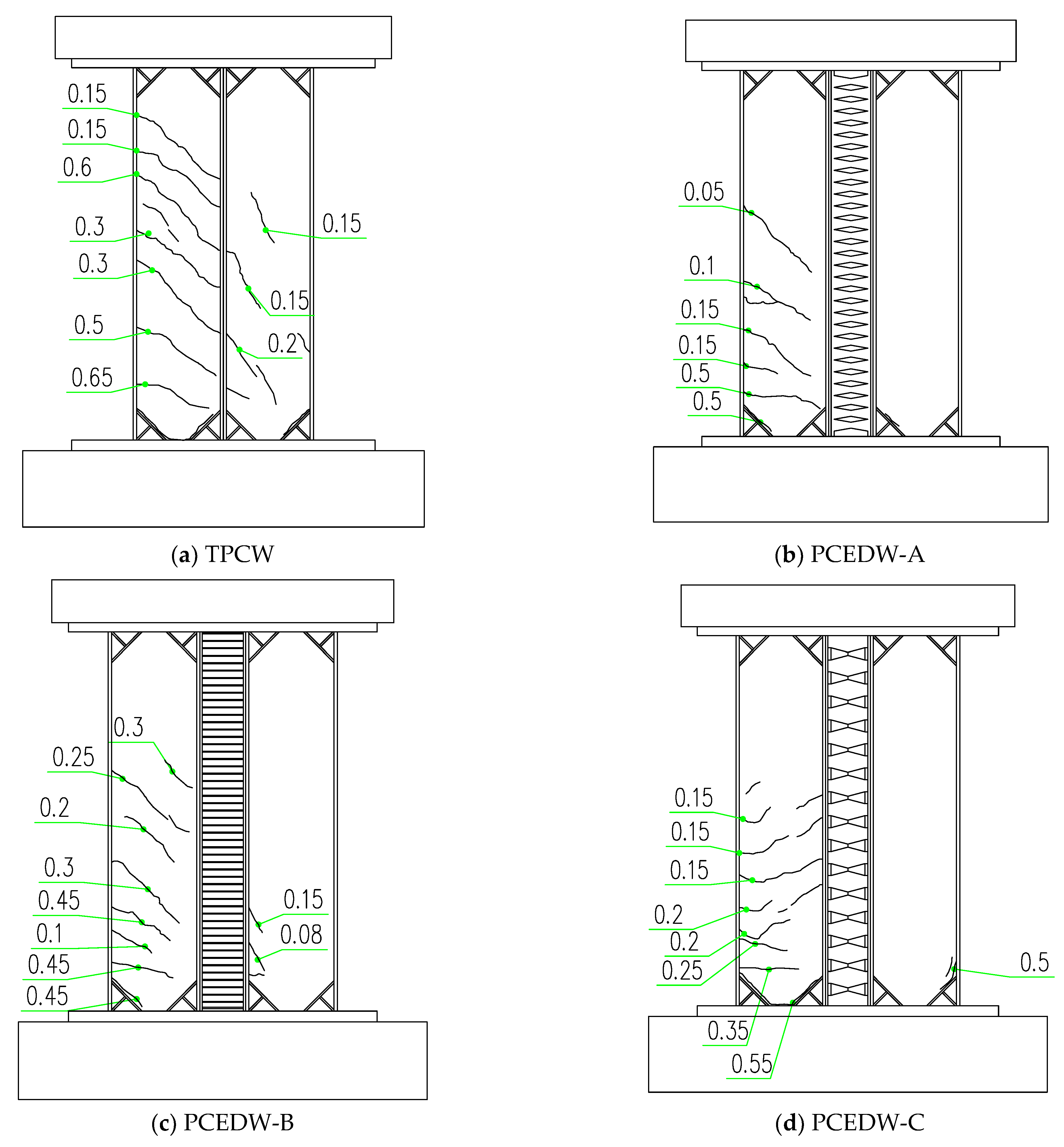
3.1. Development of Structural Damage

Figure 5 shows the variation in sample concrete crack propagation with loading based on DIC measurement, and Figure 6 presents the comparison curves of maximum crack width in positive and negative loading under different levels. It can be seen that when the drift ratio is loaded to 1/400, cracks appear in the middle lower position of specimens TPCW and PCEDW-C, and specimen TPCW has more cracks than PCEDW-C, while specimens PCEDW-A and PCEDW-B do not show cracks. In addition, it can be found that the DIC-based measurement method can observe very small cracks in the samples, indicating that this measurement method can accurately record the crack propagation process of the specimen, which is the same as in references [25,26].
When the drift ratio reaches 1/200, cracks in specimens TPCW and PCEDW-C further develop, while cracks in specimens PCEDW-A and PCEDW-B have just begun to develop. When loaded to a drift ratio of 1/50, all four groups of specimens show cracks that penetrated the shear wall, but the number and width of cracks are the highest for the TPCW. From the perspective of crack damage in the concrete samples, specimens PCEDW-A and PCEDW-B are the best, followed by specimens TPCW and PCEDW-C. In addition, from the comparison curve of the maximum crack width of concrete, it can also be seen that the maximum crack width of specimens PCEDW-A and PCEDW-B is always small with the increase in the test loading, while the crack width of specimen PCEDW-C is the largest. It is worth noting that specimens TPCW and PCEDW-C have already failed at the drift ratio of 1/50, so only the maximum crack width comparison of specimens PCEDW-A and PCEDW-B is provided at the drift ratio of 1/37.

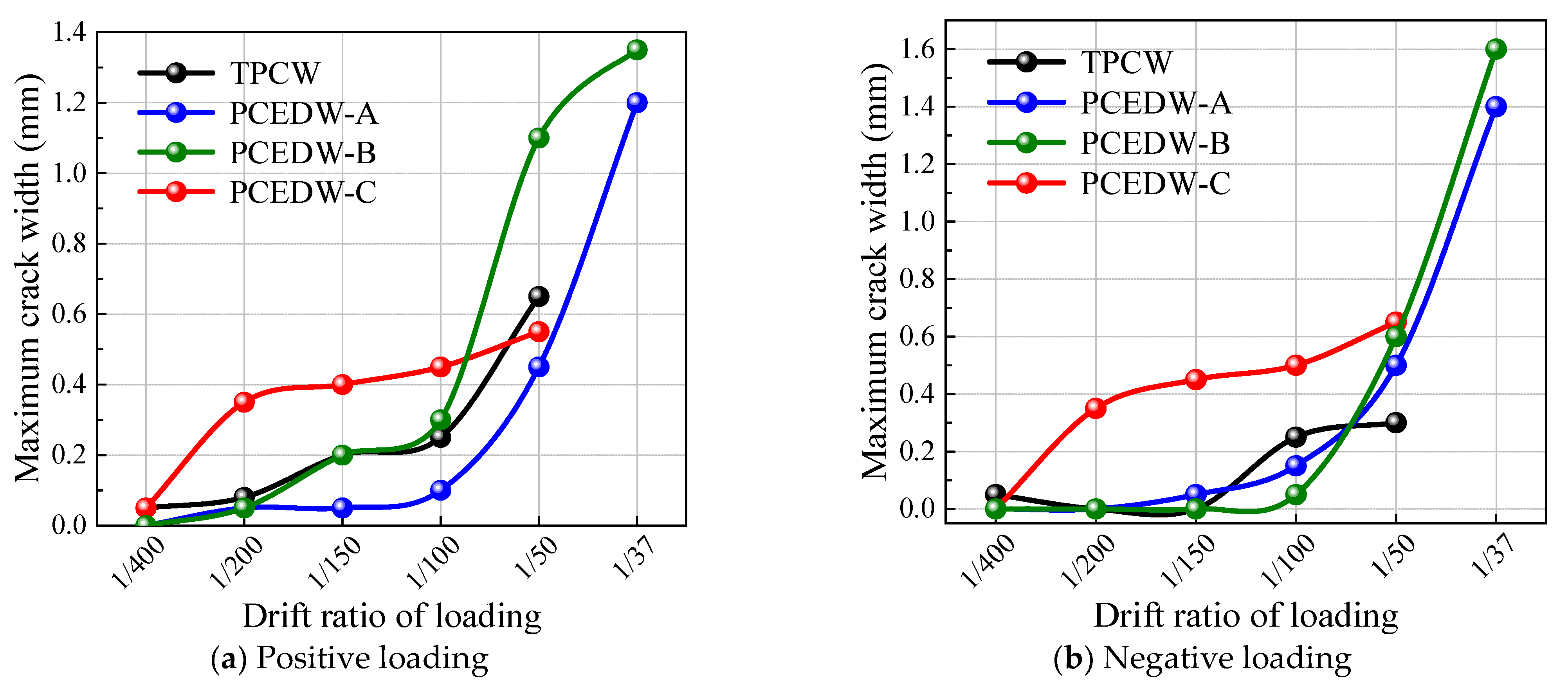
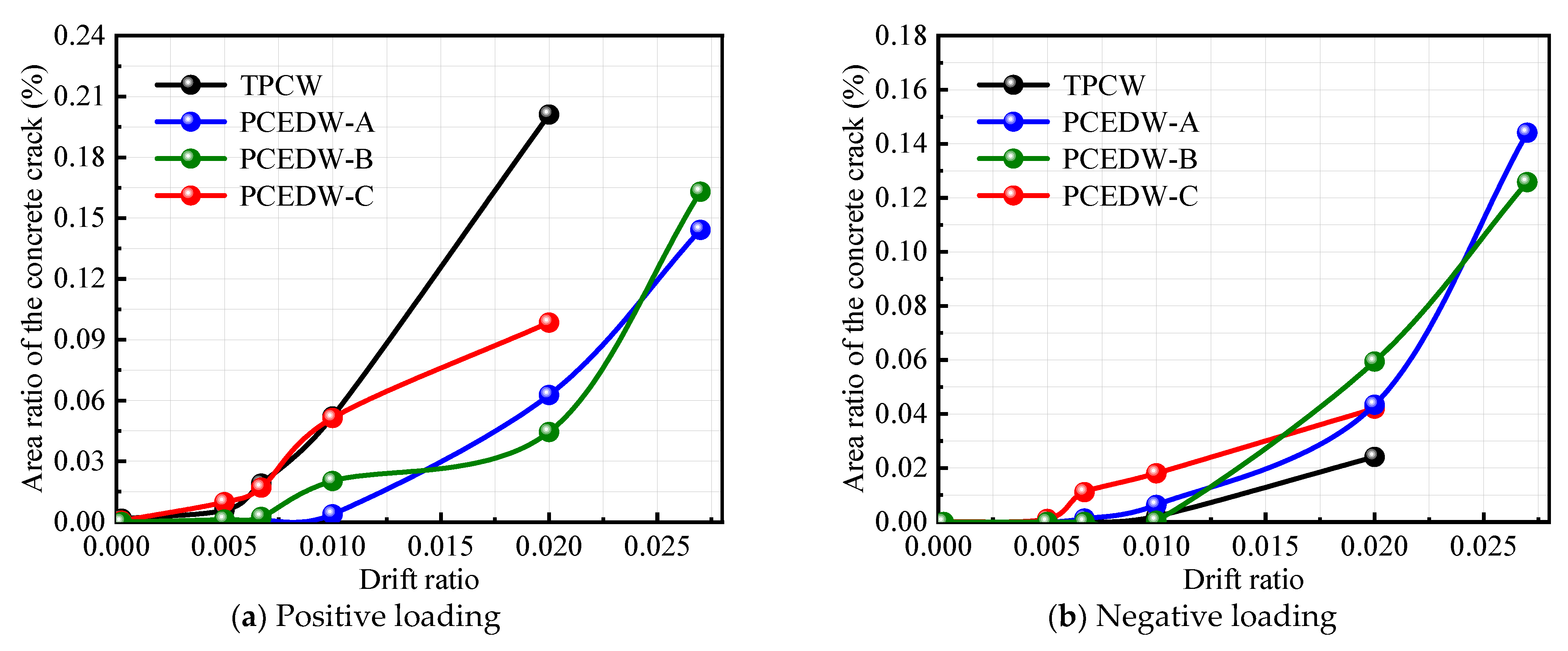
3.2. Area Ratio of the Concrete Crack

In addition to the crack width, there is also a parameter that can more accurately reflect the degree of damage to concrete, namely the crack area ratio r [1], whose calculation formula is as follows:
r = A c r A = ( w c r l c r ) A
where Acr is the total area of cracks, A is the monitored surface area of cracks, wcr is the width of cracks, and lcr is the length of cracks.
Figure 7 shows the crack development status and corresponding crack width of each test sample at the drift ratio of 1/50. Figure 8 shows the maximum crack area ratio of concrete for each test sample at the maximum displacement of positive and negative cycles. When the drift ratio is 1/50, the maximum crack width of specimens TPCW, PCEDW-A, PCEDW-B, and PCEDW-C are 0.65 mm, 0.45 mm, 0.5 mm, and 0.55 mm, respectively. Similarly, the crack area ratio of specimen TPCW is also larger than that of other test samples. For example, when the drift ratio is loaded to +1/150, the concrete crack area ratios of specimens TPCW, PCEDW-A, PCEDW-B, and PCEDW-C are 0.0190%, 0.0010%, 0.0169%, and 0.0025%, respectively; When the drift ratio is loaded to +1/100, the corresponding concrete crack area ratios are 0.0521%, 0.0514%, 0.0038%, and 0.0202%, respectively. It can be explained that by adding energy-dissipation devices in the middle of the composite shear wall, the cracking of the specimen and the crack width can be delayed to a certain extent, which helps to improve the overall mechanical behavior of the assembled composite energy-dissipation shear-wall specimen [12,13].

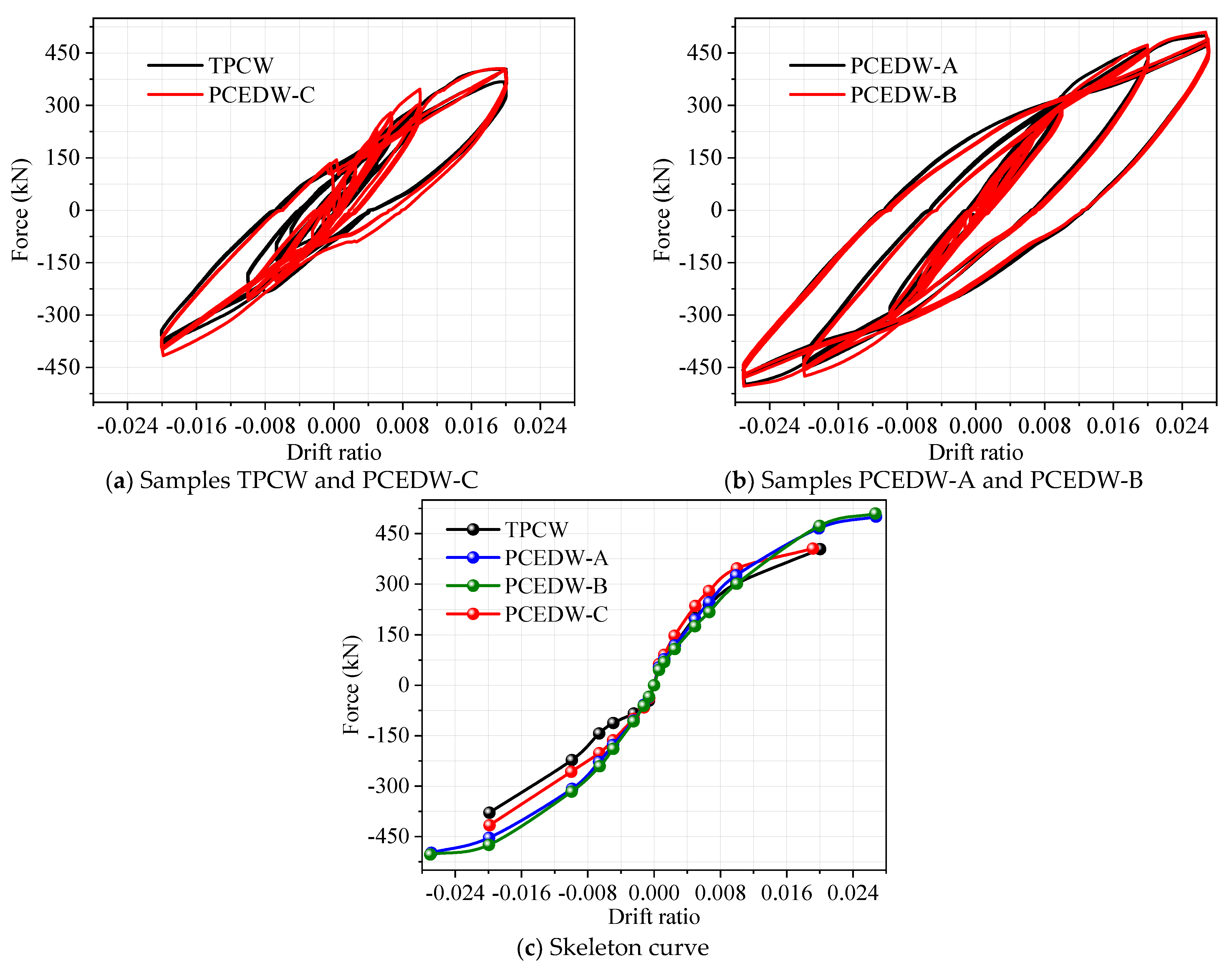
3.3. Load–Displacement Relationship

Figure 9 shows a comparison of hysteresis curves and skeleton curves for four experimental samples. It can be seen that as the drift ratio increases, the bearing capacity of each test sample shows a gradually increasing trend. When the drift ratio reaches 1/50 the maximum bearing capacities of specimens TPCW, PCEDW-A, PCEDW-B, and PCEDW-C are 403.83 kN, 459.39 kN, 473.08 kN, and 405.52 kN, respectively (the first cycle). Compared with specimen TPCW, the ultimate bearing capacities of specimens PCEDW-A, PCEDW-B, and PCEDW-C are increased by 13.76%, 17.15%, and 0.42%, respectively, indicating that specimens PCEDW-A and PCEDW-B have the best bearing performance, and their maximum bearing capacities are comparable, only differing by 2.3%.
At a loading drift ratio of 1/50, the maximum bearing capacities of the four specimens after the second cycle of loading are 401.52 kN, 457.72 kN, 457.58 kN, and 402.13 kN, respectively. The maximum bearing capacities after the third cycle are 366.88 kN, 440.56 kN, 440.64 kN, and 380.24 kN, respectively. It can be seen that the bearing capacities of specimens PCEDW-A and PCEDW-B under different loading cycles are higher than that of specimens TPCW and PCEDW-C. In addition, as the number of loading cycles increases, the bearing capacity of the specimens decreases to varying degrees. Under the three cycles, the maximum bearing capacity of the specimens TPCW, PCEDW-A, PCEDW-B, and PCEDW-C decreases by 9.15%, 4.10%, 6.86%, and 6.23%, respectively. Among them, the bearing capacity of specimen PCEDW-A decreases the least, by only 4.10%, indicating that the sample with the metal damper using a horizontal diamond-shaped hole can provide the best mechanical performance [27].

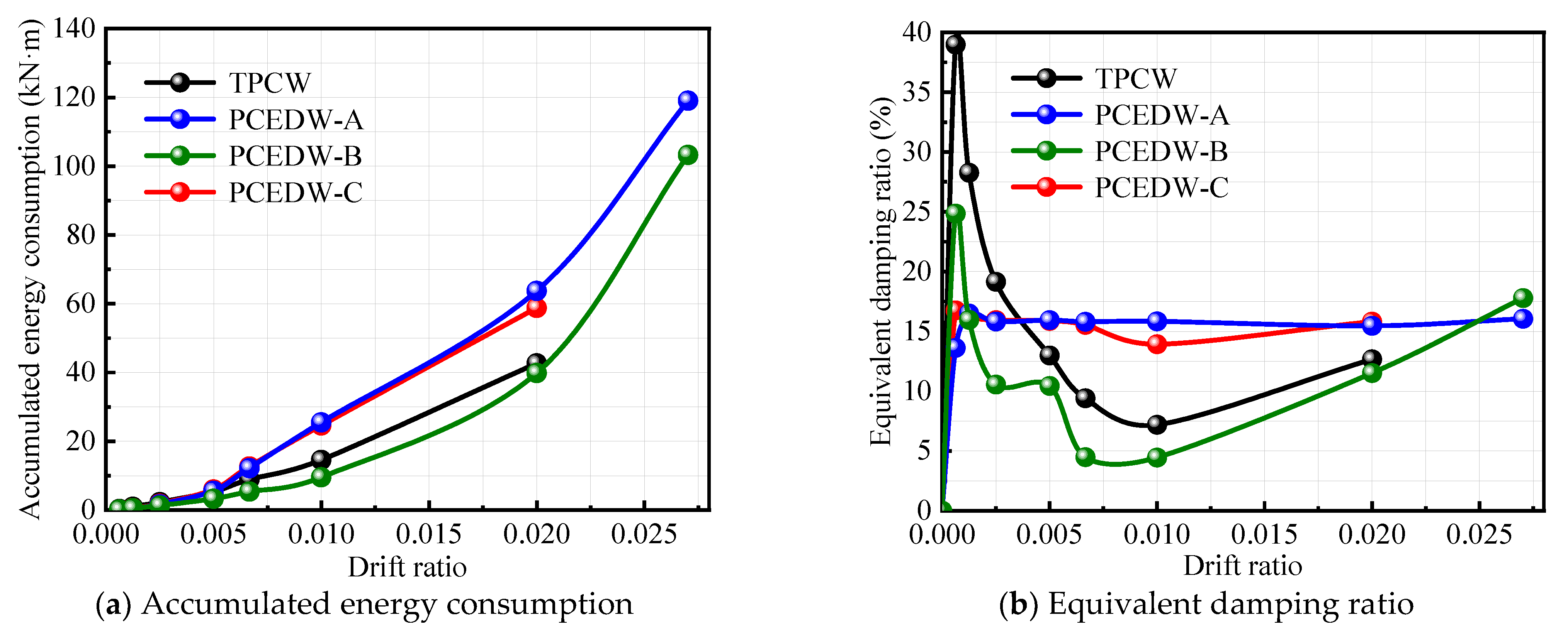
3.4. Energy-Dissipation Characteristic

Figure 10 shows the cumulative hysteresis energy-dissipation characteristics and equivalent viscous damping ratio of the testing specimens. When the displacement angle is loaded to 1/100, the cumulative hysteresis loop areas of specimens TPCW, PCEDW-A, PCEDW-B, and PCEDW-C are 14.57 kN m, 25.52 kN m, 9.55 kN m, and 24.60 kN m, respectively. The equivalent damping ratios are 7.18%, 15.84%, 4.44%, and 13.92%, respectively. It can be found that specimen PCEDW-A has the highest cumulative energy dissipation and equivalent damping ratio, indicating that the specimen using the horizontal diamond-shaped-hole metal damper (PCEDW-A) has the optimal energy-dissipation characteristics. The main reason for the highest equivalent damping ratio of specimen PCEDW-A is that the energy-dissipation module using a horizontal opening method exhibits significant yield behavior in its steel-plate components under loading. However, the energy-dissipation module with vertical openings did not fully utilize its energy-dissipation performance due to the high-volume steel-plate components. The reason is that the metal damper designed with a vertical steel plate has a high vertical height. During the loading process, only the parts connected to the connectors at the upper and lower ends yield energy dissipation, while the middle steel plate is still in an elastic state, so its energy consumption capacity cannot be fully utilized [27]. Similarly, the energy-dissipation module using double-cone energy dissipators has a lower equivalent damping ratio due to its much higher lateral stiffness than steel plates, as only a portion of the material has entered the state of yielding energy dissipation [28].
In addition, although the cumulative energy dissipation and equivalent damping ratio of the double-cone metal damper specimen (PCEDW-C) are also relatively large, the specimen has already experienced damage failure when loaded to 1/50. So, it is not optimal in terms of overall performance. Similarly, although it was found previously that specimen PCEDW-B has almost identical load-bearing mechanical properties to specimen PCEDW-A, the cumulative energy dissipation and equivalent damping ratio of this specimen are relatively small at different loading levels, so it is not the optimal solution in terms of overall performance, once again. Therefore, taking into account the load-bearing capacity and energy-dissipation characteristics of the specimens, the experimental specimen (PCEDW-A) using a horizontal diamond-shaped perforated metal damper exhibits the optimal mechanical behavior.

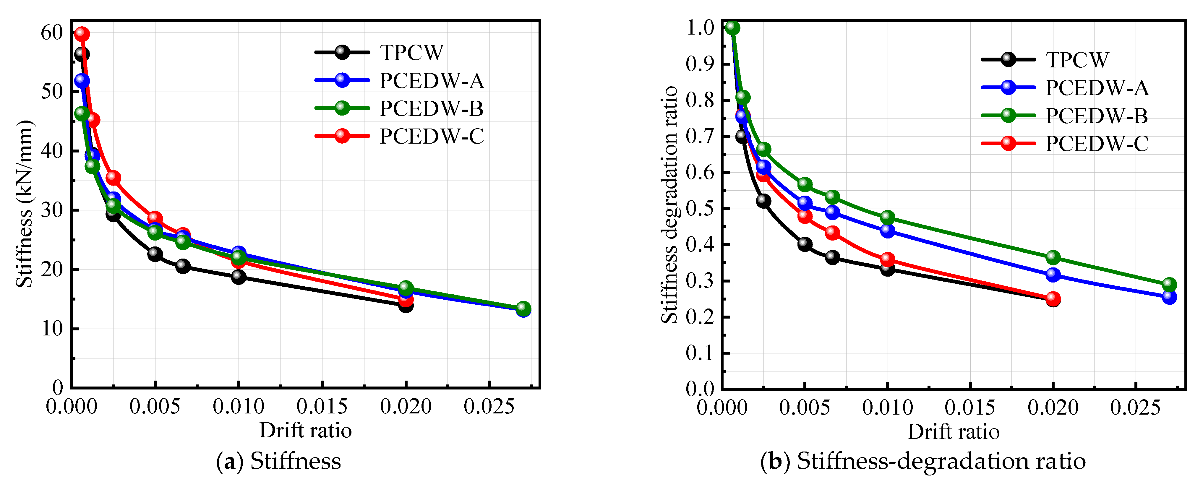
3.5. Stiffness Degradation

The residual strength and safety indicators of component ductility can reflect stiffness degradation [29]. Figure 11 shows the secant stiffness and stiffness-degradation ratio of four sets of specimens. The initial stiffness values of specimens TPCW, PCEDW-A, PCEDW-B, and PCEDW-C are 51.80 kN/mm, 56.27 kN/mm, 46.26 kN/mm, and 59.68 kN/mm, respectively. It can be observed that specimen PCEDW-C has the highest initial stiffness, followed by specimen PCEDW-A, with a difference of only 5.7% between the two. In addition, the stiffness of specimens TPCW and PCEDW-C decreases rapidly. At the drift ratio of 1/50, specimen PCEDW-B has the highest stiffness, followed by specimen PCEDW-A. This indicates that although the use of double-cone metal dampers (PCEDW-C) can provide maximum stiffness at the initial moment, it quickly decreases with the increase in the drift ratio, while the specimens using vertical and horizontal diamond-shaped perforated metal dampers (PCEDW-A, PCEDW-B) have the smallest stiffness degradation, and the difference between the two is also small [29].

4. Conclusions

A new prefabricated composite energy-dissipation shear-wall system is proposed in this study. A comparative mechanical performance study was conducted on different energy-dissipation module designs based on low-cycle-reciprocating-loading tests. The following conclusion can be drawn:
(1) Due to the delay in the development of concrete damage plasticity, and the number and range of cracks under loading, the proposed prefabricated composite energy-dissipation shear walls, namely PCEDW-A and PCEDW-B, have good deformation and mechanical behaviors.
(2) By adding a reasonable energy-dissipation module design to the composite shear walls, the development of concrete cracks can be effectively suppressed, thereby improving the mechanical behavior of prefabricated shear-wall structures. At a drift ratio of 1/50, the concrete crack area ratios of specimens TPCW and PCEDW-A were 0.0190% and 0.0010%, respectively, with the former being nearly twice as large as the latter.
(3) Compared with specimen TPCW, the ultimate bearing capacities of specimens PCEDW-A and PCEDW-B were increased by 13.76% and 17.15%, respectively. In addition, by adding the metal dampers with horizontal and vertical diamond-shaped openings in the composite shear wall, the stiffness-degradation effect of these two specimens was effectively suppressed, resulting in better structural mechanical performance.
(4) Although specimens PCEDW-A and PCEDW-B have similar ultimate bearing capacities, the energy-dissipation capacity of PCEDW-A is much higher than that of PCEDW-B. When the drift ratio was 1/100, the equivalent damping ratios of specimens PCEDW-A and PCEDW-B were 15.84% and 4.44%, respectively, with the former increasing by nearly four times compared to the latter. Taking into account the load-bearing capacity and energy-dissipation characteristics, specimen PCEDW-A using a horizontal diamond-shaped perforated metal damper exhibits the optimal mechanical behavior. In the future, further research will be conducted on this system with energy-dissipation modules comprising different materials, such as low-yield point steel, high-damping alloys, etc., so as to further improve the mechanical behavior of the proposed composite energy-dissipation shear wall.

Author Contributions

Investigation and Methodology, L.W.; Supervision and Visualization, X.W.; Formal analysis and Conceptualization, J.F.; Visualization and Funding acquisition, Y.W.; Software, Writing—original draft, and Writing—review & editing, D.W. All authors have read and agreed to the published version of the manuscript.

Funding

This research was funded by China National Natural Science Foundation (52178467), and the project of 110 kV Xindongqu transmission and substation in Shantou (030500WS22230001).

Data Availability Statement

The data presented in this study are available in article.

Acknowledgments

All statements, results, and conclusions are those of the researchers and do not necessarily reflect the views of these foundations. The authors also sincerely thank the anonymous reviewers for their insightful comments and suggestions.

Conflicts of Interest

Liuhuo Wang was employed by the company Guangdong Power Grid Co., Ltd., Xiaohui Wu and Yanfeng Wang were employed by Power Grid Planning Research Center of Guangdong Power Grid Co., Ltd., Jie Feng was employed by Shantou Power Supply Bureau of Guangdong Power Grid Co., Ltd. The remaining author declare that the research was conducted in the absence of any commercial or financial relationships that could be construed as a potential conflict of interest.

References

  1. Wang, D.; Han, Q.; Xu, S.; Zheng, Z.; Luo, Q.; Mao, J. Damage and deformation of a new precast concrete shear wall with plastic damage relocation. Steel Compos. Struct. Int. J. 2023, 48, 385–403. [Google Scholar]
  2. Chang, R.; Zhang, N.; Gu, Q. A review on mechanical and structural performances of precast concrete buildings. Buildings 2023, 13, 1575. [Google Scholar] [CrossRef]
  3. Han, Q.; Wang, D.; Li, J.; Yasir, N. Accurate equivalent analysis models and performance evaluation of precast concrete shear walls. Structures 2024, 70, 107696. [Google Scholar] [CrossRef]
  4. Qiao, Q.; Ye, M.; Liu, W.; Xu, H.; Cao, W. Seismic performance evaluation of prefabricated concrete shear walls with anchorage defects. Eng. Struct. 2024, 314, 118392. [Google Scholar] [CrossRef]
  5. Li, Y.; Yao, Z.; Dong, W.; Zhao, S. Study on seismic performance of the prefabricated shear wall with different reinforcement methods based on recycled bead steel wire. J. Build. Eng. 2025, 99, 111514. [Google Scholar] [CrossRef]
  6. Zhang, X.; Qin, Y.; Chen, Z. Experimental seismic behavior of innovative composite shear walls. J. Constr. Steel Res. 2016, 116, 218–232. [Google Scholar] [CrossRef]
  7. Guo, Y.; Hong, Q.; Zhou, M. Tests and analysis on hysteretic behavior of buckling-restrained steel plate shear wall. J. Build. Struct. 2009, 30, 31–40. [Google Scholar]
  8. Lin, Q.; Deng, Z.; Huang, Y.; Hu, Y. Experimental analysis on energy dissipation mechanism and seismic performance of steel truss coupling beam-coupled shear wall structure. J. Civ. Archit. Environ. Eng. 2014, 36, 16–24. [Google Scholar]
  9. Wei, M.; Richard Liew, J.Y.; Xiong, M.; Fu, X. Hysteresismodel of a novel partially connected buckling-restrained steel plate shear wall. J. Constr. Steel Res. 2016, 125, 74–87. [Google Scholar] [CrossRef]
  10. Wei, M.; Richard Liew, J.Y.; Fu, X. Panel action of novel partially connected buckling-restrained steel plate shear walls. J. Constr. Steel Res. 2017, 128, 483–497. [Google Scholar] [CrossRef]
  11. Jin, S.; Ou, J.; Richard Liew, J.Y. Stability of buckling-restrained steel plate shear walls with inclined-slots: Theoretical analysis and design recommendations. J. Constr. Steel Res. 2016, 117, 13–23. [Google Scholar] [CrossRef]
  12. Wang, P.; Xue, Z.; Xiao, S. Seismic behavior of Self-Buckling-Restrained Steel Plate ShearWall made by two incline-slotted infill plates. J. Constr. Steel Res. 2017, 133, 47–64. [Google Scholar] [CrossRef]
  13. Dong, H.; Jiang, F.; Cao, W.; Wu, H.; Liu, H. Study on seismic behavior of composite shear wall with paralleled CFST columns and steel plate energy-consuming connectors. J. Earthq. Eng. Eng. Vib. 2012, 32, 103–110. [Google Scholar]
  14. Wu, Y.; Dai, C.; Zhou, Z.; Jiang, K. Seismic behavior of shear dominant bolted endplate steel coupling beam of composite coupled shear wall. J. Build. Struct. 2014, 35, 255–261. [Google Scholar]
  15. Dong, J. Seismic Performance of Shear Wall Structure with Novel SMA Dampers in Coupling Beams. Master’s Thesis, Northeast Forestry University, Harbin, China, 2011. [Google Scholar]
  16. Sun, J.; Sun, Y.; Cai, Y.; Li, Y. Loadding on energy dissipating low-rise concrete shear wall with mezzanine rubber cushion. Earthq. Eng. Eng. Vib. 2003, 23, 190–195. [Google Scholar]
  17. Li, H.; Xu, Q.; Wu, B. Energy dissipated low-rise concrete shear wall with tube filled with concrete. J. Harbin Univ. C. E. Archit. 2000, 33, 18–23. [Google Scholar]
  18. Zhou, T.; Xu, M.; Ren, Z. Study on prefabricated composite shear wall cladding anti-shedding connection structure. Structures 2024, 66, 10682. [Google Scholar] [CrossRef]
  19. Shen, S.-D.; Cui, Y.; Pan, P.; Ren, J.-Y. Development of prefabricated composite energy-dissipating slotted shear wall. Eng. Struct. 2019, 199, 109577. [Google Scholar] [CrossRef]
  20. Zhang, Y.; Cui, Y.; Zhang, D.; Liu, Z.; Li, Y. Cyclic performance of prefabricated buckling-restrained steel plate shear wall with two-side connections. J. Constr. Steel Res. 2025, 227, 109293. [Google Scholar] [CrossRef]
  21. Li, M.; Li, Z.; Gao, C.; Zhang, L.; Ma, H.; Wang, P. Experimental study on seismic behaviour of precast composite shear wall with ceramsite foam concrete interlayer. Structures 2025, 74, 108512. [Google Scholar] [CrossRef]
  22. Tong, X.; Zhou, Y.; Gan, L.; Wu, J.; Guo, H. Bearing capacity of horizontal joints of UHPC prefabricated shear walls with vertical bars splicing by cold-extrusion sleeves. Case Stud. Constr. Mater. 2024, 20, e02997. [Google Scholar] [CrossRef]
  23. Mei, C.; Zhang, Y.; Wang, D.; Wu, C.; Xu, Y. Parameter Optimal Investigation of Modular Prefabricated Two-side Connected Buckling-Restrained Steel Plate Shear Wall. Structures 2021, 29, 2028–2043. [Google Scholar] [CrossRef]
  24. Sun, J.; Wang, T.; Sun, H.; Ruan, S.; Qiu, H. Parametric study on lateral behavior of totally precast RC shear wall with horizontal bolted connection. Structures 2023, 57, 105100. [Google Scholar] [CrossRef]
  25. Bi, Y.; Yao, Z.; Qin, Y.; Kali, A.; Chen, Q.; Niyazi, H. Seismic performance of precast concrete shear walls based on grouted corrugated metallic duct hybrid connection. Constr. Build. Mater. 2024, 450, 138576. [Google Scholar] [CrossRef]
  26. Seemab, F.; Schmidt, M.; Baktheer, A.; Classen, M.; Chudoba, R. Automated detection of propagating cracks in RC beams without shear reinforcement based on DIC-controlled modeling of damage localization. Eng. Struct. 2023, 286, 116118. [Google Scholar] [CrossRef]
  27. Chen, H. Study on Improvement of Seismic Structure of New Type Modular Composite Shear Wall. Master’s Thesis, Guangzhou University, Guangzhou, China, 2019. [Google Scholar]
  28. Zhou, Y.; Huang, H.; Zhu, Y. Design and FE analysis for an assembled biconical energy dissipator(BED). J. Vib. Shock 2012, 31, 131–139. [Google Scholar]
  29. Huang, Z.; Zhang, S.; Guo, L. Cyclic behavior of low shear-span ratio dovetailed profiled steel–concrete composite shear walls. J. Build. Eng. 2022, 59, 105094. [Google Scholar] [CrossRef]
Figure 1. Sample design.
Buildings 15 00941 g001aBuildings 15 00941 g001b
Figure 2. Sample performance testing.
Buildings 15 00941 g002
Figure 3. Loading design.
Buildings 15 00941 g003
Figure 4. Installation of data collection system.
Buildings 15 00941 g004
Figure 5. Development of concrete damage in specimens based on DIC measurement.
Buildings 15 00941 g005
Figure 6. Maximum crack width of concrete under different loading levels.
Buildings 15 00941 g006
Figure 7. Width of concrete crack under drift ratio of 1/50 rad (unit: mm).
Buildings 15 00941 g007
Figure 8. Area ratio of the concrete crack.
Buildings 15 00941 g008
Figure 9. Hysteresis and skeleton curves of the samples.
Buildings 15 00941 g009
Figure 10. Energy-dissipation characteristic of the samples.
Buildings 15 00941 g010
Figure 11. Stiffness-degradation characteristic of the samples.
Buildings 15 00941 g011
Table 1. Performance parameters of steel samples.
TypeSizeSampleYield Strength
(MPa)
Tensile Strength
(MPa)
Ratio of Intensity
and Yield Strength
Elastic Modulus
(×105 MPa)
Inner
steel plate
3 mma/b/c415/389/406510/494/5031.23/1.27/1.241.94/1.96/1.97
Average4035021.251.96
Steel plate of
metal damper
2 mma/b/c420/410/401500/510/5121.19/1.24/1.281.95/1.95/1.92
Average4105071.241.94
Connecting
steel plate
10 mma/b/c337/322/314461/451/4581.37/1.40/1.462.06/2.12/2.00
Average3244571.412.06
Steel bar8 mma/b/c307/302/314447/440/4411.47/1.47/1.422.09/2.12/2.06
Average3084431.452.09
Table 2. Performance parameters of concrete samples.
SampleCompressive
Strength (MPa)
Convert Axial Compressive
Strength (MPa)
Convert Axial Tensile
Strength (MPa)
Elastic Modulus
(MPa)
a/b/c31.52/30.30/31.9721.09/20.31/21.422.44/2.33/2.4432,439/31,979/32,601
Average31.2720.942.4132,339
Disclaimer/Publisher’s Note: The statements, opinions and data contained in all publications are solely those of the individual author(s) and contributor(s) and not of MDPI and/or the editor(s). MDPI and/or the editor(s) disclaim responsibility for any injury to people or property resulting from any ideas, methods, instructions or products referred to in the content.

