
A Weak SNR Signal Extraction Method for Near-Bit Attitude Parameters Based on DWT


1
Shaanxi Key Laboratory of Measurement and Control Technology for Oil and Gas Wells, Xi’an 710065, China
2
College of Electronic Engineering, Xi’an Shiyou University, Xi’an 710065, China
3
School of Engineering, Royal Melbourne Institute of Technology, P.O. Box 71, Bundoora, VIC 3083, Australia
*
Author to whom correspondence should be addressed.
Actuators 2022, 11(11), 323; https://doi.org/10.3390/act11110323
Submission received: 15 September 2022
/
Revised: 23 October 2022
/
Accepted: 31 October 2022
/
Published: 7 November 2022
(This article belongs to the Special Issue Designing, Sensing, Instrumentation, Diagnosis, Controlling, and Integration of Actuators in Digital Manufacturing Especially in Aerospace Engineering)
Abstract
:In practice, the near-bit signals are usually accompanied by noises generated by drilling tool vibration and high-speed rotary. This study introduces discrete wavelet transform to a well drilling area and presents a new weal signal extraction algorithm, which can eliminate the vibration and rotary noises effectively and obtain the useful gravity attitude signals based on the discrete wavelet transform through a hard threshold method. The effectiveness and usefulness of our method are verified via Matlab simulation and actual drilling data.
1. Introduction
With the development of global oil/gas exploration, more and more attention are focused on unconventional oil/gas reservoirs, e.g., under ocean and deep and super-deep layers [1]. Oil/gas explorations have two problems to deal with. The first one is to enhance oil/gas recovery, to exploit difficult reserves, to develop remaining oil resources, and special economic marginal reservoirs such as low permeability, ultra-thin, heavy oil and ultra-heavy oil reserves, as well as scarce resources such as shale gas and coalbed methane, which requires the development of horizontal and directional drilling technology; The second one is to explore oil resources which are more and more concentrated in deep strata and deep-sea areas by vertical drilling of deep/ultra-deep wells. In exploration of oil/gas resources, steerable drilling is the key technology to solve these two problems [2].
The working principle diagram of the drilling system is given in Figure 1. It is crucial to have real-time, accurate, continuous, and dynamic measurements of downhole dynamic spatial attitude parameters (such as well inclination, azimuth, and tool surface angle, etc.) for real-time steering control of guided drilling tools. And it is common to use measurement while drilling (MWD) technology to obtain dynamic measurements of downhole attitude [3,4,5]. Its main characteristic is firstly to do well logging while drilling, then extract a real-time measurement of downhole attitude parameters, upload them to the ground, and finally, carry out feedback control of the downhole control system according to downhole attitude parameters to ensure dynamic stability of borehole trajectory.
However, practically the steering tool stability control platform connects both ends of the drill pipe and the bearing. The inertial components (acceleration sensors) are installed inside the steering tool stability control platform. Thus, rock cutting of the drill bit, as well as the collision of the drill string against the wall, and the high-speed rotation of the tool along with the drill string, will result in strong vibration signals and contaminate the dynamical measurements of the steering tool attitude parameters, which herein results in a large deviation when calculating attitude parameters while drilling and to a certain extent, could deteriorate the well trajectory control accuracy [5].
To deal with this problem, an unscented Kalman filter was proposed for the attitude of the rotary steering drill tool in [6], which effectively improves the accuracy of attitude measurements. Based on preset Euler rotation, a vertical attitude measurement method was given in [7], which can obtain the original signal amplitude of attitude measurement and reduce the solution error, a linearized model with the actual situation was presented to accurately describe the nonlinear factors and the stability control problem of the inertial navigation platform is solved in [8,9] after analyzing the inertial navigation platform of rotary steering drill. A non-orthogonal four-axis force accelerometer attitude measurement method was given in [10], which realizes the real-time measurement of downhole attitude of the modulated steering drilling tool. Through state space model for continuous real-time measurement of drilling trajectory, a new Kalman filter was presented to reduce the systematic error in [5]. A dynamic attitude measurement scheme of anti-differential adaptive filtering was conducted in [11] to handle the problem of attitude parameters uncertainty in dynamic measurement, and it uses the reasonable distribution information of equivalent weight function and adaptive factor to alleviate the drilling tool vibration influence on dynamic attitude measurement. Another multi-source dynamic attitude combination measurement method is proposed adopting the quaternion-based untracked Kalman filtering method to filter the vibration interference signals. The existing methods may inevitably damage the useful signals to a certain extent while removing noises based on the filtering scheme, which could lead to severe distortion of steerable drilling.
To improve the accuracy of attitude parameters, a new scheme is desired to effectively extract gravitational acceleration signals from the complex interferences.
Wavelet transform is a local transformation of space (time) and frequency, so it can effectively extract information from data. Through the operation functions such as stretching and translation, the useful signal can be refined and analyzed at multiple scales. Various approaches based on the discrete wavelet transform (DWT) have been explored and used effectively in various areas, such as signal and image compression, statistics and numerical analysis [2,12,13,14,15] due to the powerful decomposition and reconstruction of DWT. However, few results have been reported in near-bit signal processing areas. We proposed a new method based on DWT in [16] to deal with the extraction of near-bit weak signal noise ratio (SNR) signal. In this paper, we will give more details of our scheme through a hard threshold to improve the accuracy of attitude parameters for steerable drilling control and conduct actual drilling well data to verify our method.
After analyzing the characteristics of the original weak signals contaminated by strong vibration and rotary, we first decompose the original near-bit measured data, then cut off the detailed coefficients using a threshold, which is adaptively designed, and finally reconstructs the data. Daubechies 5 (Db5) is adopted at a suitable level of decomposition.
This paper is organized as follows. In Section 2, backgrounds and basic characteristics of the near-bit signals are given. Section 3 introduces the DWT algorithm, and presents details of our proposed extraction scheme using a hard threshold. Then Matlab simulation verification and actual experiments results are given in Section 4 to illustrate the utility and effectiveness of our extraction algorithm. Conclusions are contained in Section 5.
2. Backgrounds
We will discuss the influence of near-bit vibration and tool rotation on attitude parameter measurements give and the calculation process of attitude parameter measurement.
2.1. Static Drilling and Dynamic Drilling
Traditionally the sensor probe distance is far away from the bit and drilling tools to weaken the interference affection of vibration and tool rotary on the measurement accuracy. Thus, the real-time trajectory can not be measured in static drilling. Taking the accelerometer along x axis, for example, its output is the element of gravity
Without stopping drilling, dynamic measurements could provide real-time and dynamic data of the drilling tool. However, in dynamic near-bit measurement processing, the output of each accelerometer consists of not only the components of gravity, but also the centrifugation acceleration resulting from the instrument rotation, vibration acceleration and impact acceleration when drilling. In dynamic measurement of the output of each accelerometer can be described by [17]
where is the component of gravity acceleration, is the vibration acceleration caused by strong vibration, is the centrifugation acceleration resulted from high-speed rotary, along x axis, respectively. It is crucial to effectively obtain from the contaminated measurement signals to improve the dynamic measurement accuracy.
2.2. Influence of Near-Bit Vibration on Attitude Parameters Measurements
The near-bit vibration signals have three characteristics: (1) the high- frequency characteristic formed by the teeth of the roller bit penetrating the rock; (2) the broadband characteristic of near-bit vibration; (3) the randomness characteristic of the compound motion formed by the bit teeth, roller and bit.
The amplitude of useful measurement signals are the components of gravity acceleration, which is less than g (g is gravity acceleration, 9.8 m/s2). However, the amplitude of near-bit vibration signal is generally around 10 g, and sometimes can reach the maximum value 30 g [7,18]. Therefore, the vibration acceleration signals near the drill bit are usually dozens of times than the gravity acceleration, and thus overwhelm the weak gravity acceleration signals, leading to noneffective attitude measurements.
Figure 2 shows the logging data of a well with a depth of 1740–1807 m in the west of Sichuan province, China, between 20 November and 24 November 2014. The measured well inclination angle is around 2.5°, and the high side tool face angle is basically stable at around 100°. However, as clearly demonstrated in Figure 2, the strong vibration near the drill bit introduces massive high-frequency and high amplitude noises.
2.3. Effect of High-Speed Tool Rotation on Attitude Parameter Measurements
When the guiding drilling tool rotates, given the measurement error of the accelerometer along x axis and y axis respectively, the accelerations and of the equivalent mass blocks along x axis and y axis are,
where and are the components of the gravity acceleration along x axis and y axis respectively; is the acceleration of the tangential additional inertial force along x axis, which varies with the change rate of the rotation velocity ; is the acceleration of the centrifugal force along the y axis, which varies with the square of the rotation velocity ; and and are well inclination angle and tool face angle respectively.
According to (1) and (2), when the rotation speed of the guiding drilling tool is relatively high, the gravity accelerometer installed on the drilling tool will have significant measurement noises in the different orientations of the borehole, leading to severe errors in attitude parameters measurements of the guiding drilling tool.
3. New Scheme for Gravity Acceleration Signals Extraction Based on DWT
3.1. Discrete Wavelet Transformation
Wavelet transform is a tool to study the components of the corresponding scale by using the decomposition method, which separates the data, function, or different operating frequency components. The key of wavelet transformation is a variable analysis window of time-frequency. With the window, its wide part can be used to analyze the low-frequency signal and its narrow part can be used to analyze the high-frequency signal. Therefore, wavelet transformation can provide the superior time-frequency resolution for signal analysis within all the frequency scope [19]. The ideas and foundations behind DWT come from multi-resolution analysis [12,13].
Wavelet denoising techniques were initially developed in [20] for white noise reduction. In the basic wavelet denoising, a non-linear processing is made in the wavelet domain (usually thresholding), and a reconstruction is obtained by the inverse transform. The fundamental equation in wavelet transform is given as
where produces the converging series of values, the parameters are the approximation coefficients, and are the detail coefficients.
As high-frequency components can reflect more details of signals, they are more suitable for extracting the submerged signals from hyperspectral reflectance.
3.2. Calculation Procedure of Attitude Measurement Parameters
Measurement while drilling (MWD) systems usually use three gravitational acceleration sensors along and z axes to measure the inclination angle and tool-face angle. The coordinate system is given in Figure 3. Right-handed cartesian coordinate consists of z axis along the axis of the drilling tool, x axis along the radial direction, and y axis along the tangent direction. Three-axis acceleration sensors are installed along x, y, and z, respectively.
The inclination angle is the angle between the axis of the drilling tool and the plumb line varying from 0 degrees to 180 degrees. Its measurement is based on the variation of gravity components along the well axis and the plum line as the inclination changes. We can measure the gravity components along the axis using three orthogonal acceleration sensors and then calculate the value of inclination angle by
and calculate the tool-face angle by
As we can see from above, if the measurements, of acceleration sensors are contaminated by near-bit vibration and high-speed rotation signals, we are not able to obtain exact attitude parameters, and thus will not accurately control the guiding drilling tool.
3.3. Proposed Extraction Scheme Based on DWT
It is very difficult to extract the weak attitude parameters signal from the measured signals contaminated by strong vibration and rotary directly. The signal processing method based on wavelet transform theory has the power to deal with this problem properly. The DWT algorithm has received considerable attention in various signal processing applications. Different wavelet bases satisfy different requirements of signal processing. Here we choose Daubechies wavelets as the base wavelet, which are a family of orthogonal wavelets defining a discrete wavelet transform and characterized by a maximal number of vanishing moments.
Here we propose the extraction scheme based on DWT adopting hard threshold, which firstly reconstructs the original signal through wavelet transform and then inverse transforming the wavelet coefficients. The scheme is simple and effective.
Firstly, we decompose the original signal. In this process, when designing the threshold, we choose the hard threshold method. The steps of our scheme are as follows. Here we adopt Daubechies wavelets (Db5) as the wavelet base. Take along x axis for example,
Step 1. Apply DWT and decompose the demanded signals, in which vibration and rotation noises are contained, into wavelets with different scales.
where m denotes measurements.
Step 2. Obtain the detail coefficients and approximation coefficients .
Step 3. Apply hard threshold method and set the high-frequency detail coefficients to be the designed value.
In common wavelet de-nosing methods, the threshold de-noising method deals with all level coefficients based on the corresponding strategy that is over or below a certain threshold value after performing a wavelet transform separately and inverse transforming the corresponding wavelet coefficients. Different threshold functions could reflect different strategies of wavelet coefficients greater or smaller than the given threshold value. Here we choose the hard threshold method for simplicity. In hard threshold, the absolute values of the decomposed coefficients will be compared with the specified threshold. If the compared result is smaller than or equal to the threshold, let it be zero, else the coefficients will remain.
Step 4. Based on and , calculate
where is the estimated signal of .
Step 5. Based on (6) and (7), get the two angles, inclination angle and tool-face angle, respectively.
Thus, the near-bit dynamic attitude parameters (well inclination angle, azimuth angle, and tool surface angle, etc.) will be extracted and the noises resulting from drilling tool vibration and high-speed rotary will be filtered well. Although the selection of wavelet basis has a significant influence on the results of the whole wavelet analysis without adaptability, it is simple to implement and has low calculation.
We will verify the effectiveness and accuracy of our proposed extraction scheme via MATLAB simulation data and actual drilling data from a well in China respectively.
4. Performance Evaluation and Discussion
4.1. Verification of Our Extraction Algorithm via MATLAB Simulation
Firstly, the effectiveness and accuracy of our proposed extraction scheme will be verified via MATLAB simulation where the extraction method based on DWT is denoted as EDWT and the classical low pass filter is denoted as LPF.
Here, the well inclination angle is the tool rolling frequency is 150 r/min, and the sample frequency is 203.45 Hz with 1000 points. Generate the outputs of three accelerometers along three axes and wide-band white noises with different amplitudes as the vibration disturb. Meanwhile, add DC bias to the x and y axis to simulate the centrifuge and tangential accelerations. Accordingly, Figure 4 shows the contaminated true effective signals along the time axis, which will result in a large deviation when calculating attitude parameters.
As shown in Figure 5, the filtered signals using the proposed method are given. The filtered signals using EDWT are apparently smoother than that using LPF setting the threshold at 30 Hz, and the biases of measurements along x and y axis have been removed. From the filtered results, we can see that our method is effective in extracting the gravity acceleration signals from vibration and rotation noises.
Figure 6 shows the filtered inclination angles together with the true inclination angle using EDWT and LPF. Our filtered inclination angle error is between +5° and −5°. The filtered results of tool-face angle are given in Figure 7, and our results clearly outperform that of LPF, which means our method takes the acceleration signals and eliminates the noises effectively.
Our proposed method is powerful and effective through MATLAB simulation data verification.
4.2. Verification of Our Extraction Algorithm via Actual Drilling Data
In this section, we conduct actual drilling data from a certain well in China to validate the effectiveness of our method.
Figure 8 gives real measurements of three-dimensional accelerometers from some drilling well in China. Drilling depth is 1768 m, drilling velocity is 45 r/min and the total drilling time period is 75 h. The data are measured voltage signals along axis, respectively.
Using the measurements, we cannot obtain accurate parameters due to multiple sources of noise. From Figure 8 we can see that the original measurements curve has a large fluctuation range with noise, and signals along the x-axis are damaged by noises worst.
Figure 9 shows the filtered signals along axis respectively acquired by our proposed method as well as LPF, where high-frequency noises are eliminated. The processed data along x axis has been obtained, and we can even see its peak is at 40 s. For the signals along the y axis, there is a peak at around 120 s. This is because there is a severe trough in the original curve as shown in Figure 8, and the signals are recovered using the proposed method when we reconstruct signals based on (9).
Then based on (6) and (7), the plots of inclination angle measurements and filtered inclination angles are given in Figure 10. We can see that the filtered curve using EDWT is flat and steady with accuracy between
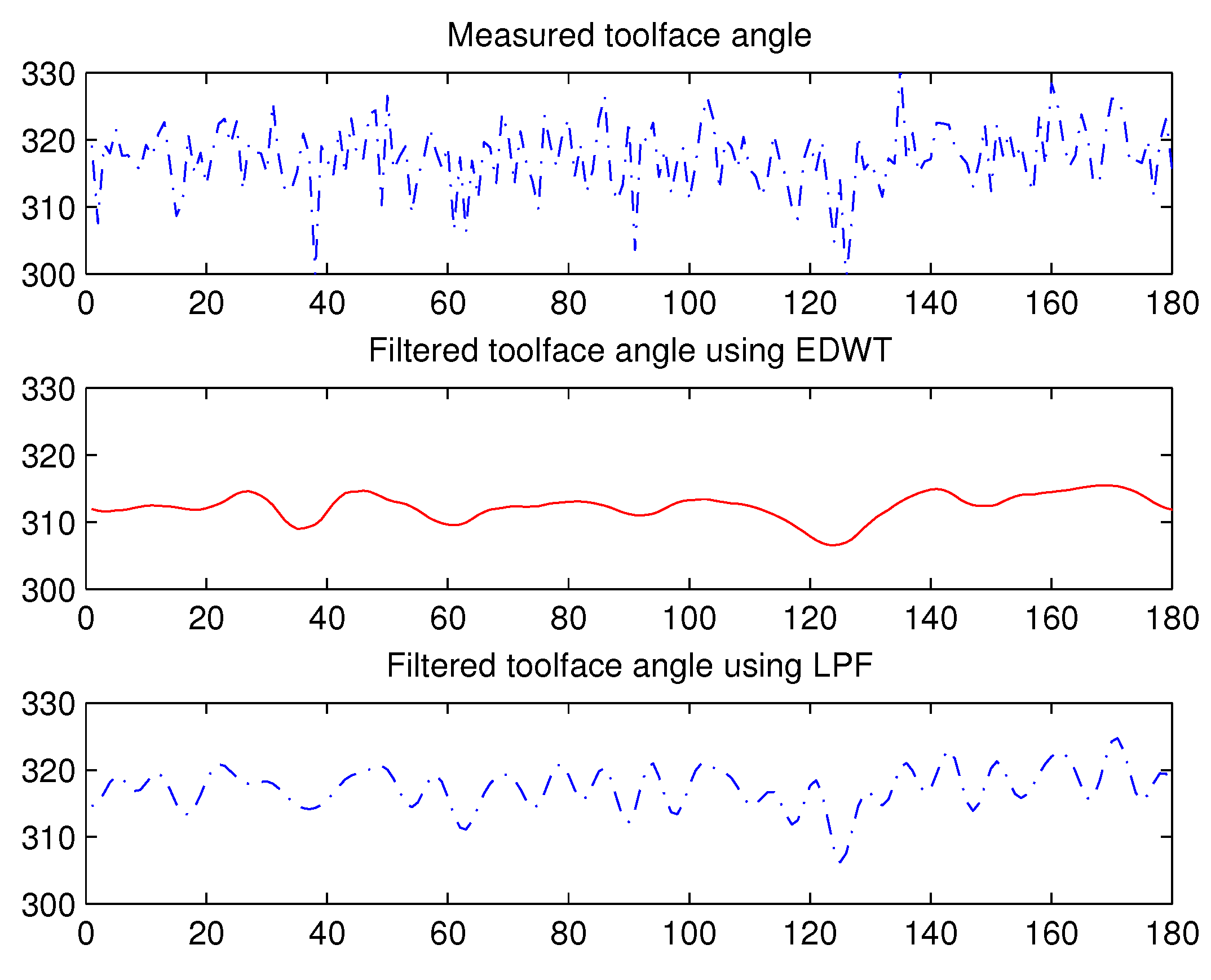
The comparison of tool face angle measurements and filtered tool face angle plots are given in Figure 11. The tool face angle using EDWT is around 317° with accuracy between .
The actual data collected by the accelerator from a real well have been conducted. The results show that vibration acceleration and rotary acceleration signals are alleviated effectively. The accuracy of the inclination angle and tool face angle meets the requirements of at-bit dynamic inclination measurement.
5. Conclusions
In this paper, DWT is introduced to the well drilling area and a new scheme to extract the weak signal from the down well is proposed, which is simple to apply. The original weak signals contaminated by strong vibration and rotary are finally constructed. Then the proposed method is validated by simulation experiments and actual well data, which proves its effectiveness and usefulness. The proposed method can be expanded to the area of inclination dynamic measurement for at-bit geosteering system or rotary steerable drilling system after actual drilling environmental data testing, and could bring possible economic effects to the oil drilling industry. Here the selection of wavelet basis has a significant influence on the results of the whole wavelet analysis, and we will make more efforts to deal with its adaptability in future.
Author Contributions
Methodology, Y.M.; supervision, Y.Z.; supervision, Y.G.; formal analysis, Y.W. All authors have read and agreed to the published version of the manuscript.
Funding
This research was funded by National Natural Science Foundation of China Enterprise Innovation and Development Joint Fund grant number U20B2029.
Data Availability Statement
Not applicable.
Conflicts of Interest
The authors declare no conflict of interest.
References
- Wang, H.; Ge, Y.; Shi, L. Technologies in deep and ultra-deep well drilling: Present status, challenges and future trend in the 13th Five-Year Plan period (2016–2020). Nat. Gas Ind. B 2017, 4, 319–326. [Google Scholar] [CrossRef]
- Yang, H.; Luo, T.; Li, L.; Rao, Y.; Li, W.; Liu, K.; Qiu, Z. Research on Drilling Bit Positioning Strategy Based on SINS MWD System. IEEE Access 2019, 7, 109398–109410. [Google Scholar] [CrossRef]
- Ledroz, A.G.; Pecht, E.; Cramer, D.; Mintchev, M.P. FOG-based navigation in downhole environment during horizontal drilling utilizing a complete inertial measurement unit: Directional measurement-while-drilling surveying. IEEE Trans. Instrum. Meas. 2005, 54, 1997–2006. [Google Scholar] [CrossRef]
- Xue, Q.; Wang, R.; Sun, F.; Huang, F.; Han, L. Continuous Measurement-While-Drilling Utilizing Strap-Down Multi-Model Surveying System. IEEE Trans. Instrum. Meas. 2014, 63, 650–657. [Google Scholar] [CrossRef]
- Xue, Q.; Leung, H.; Wang, R.; Liu, B.; Wu, Y. Continuous Real-Time Measurement of Drilling Trajectory with New State-Space Models of Kalman Filter. IEEE Trans. Instrum. Meas. 2016, 65, 144–154. [Google Scholar] [CrossRef]
- Yang, Q.; Xu, B.; Zuo, X.; Jiang, H. An unscented Kalman filter method for attitude measurement of rotary steerable drilling assembly. ACTA Pet. Sin. 2013, 34, 1168–1175. [Google Scholar]
- Cheng, W.; Pan, M.; Tang, N.; Wang, Y.; Huo, A. Vertical attitude measurement based on Euler’s pre-rotation. Chin. J. Sci. Instrum. 2014, 35, 1817–1822. [Google Scholar]
- Wang, Y.; Wang, H.; Kang, S.; Tang, N.; Huo, A. Output feedback linearization of servo platform for rotary steering drilling system. ACTA Pet. Sin. 2014, 35, 952–957. [Google Scholar]
- Wang, Y.; Fei, W.; Huo, A.; Cheng, W.; Tang, N. Electromagnetic torque feed-forward control of the turbine alternator for rotary steering drilling tools. ACTA Pet. Sin. 2014, 35, 141–145. [Google Scholar]
- Liu, Z.; Yan, W.; Kang, S.; Liu, Z.; Wang, Y.; Zhang, S. Redundant posture measurement and system reconfiguration method of steering drilling tool. ACTA Pet. Sin. 2015, 36, 1433–1440. [Google Scholar]
- Gao, Y.; Wang, Y.; Cheng, W. Robust adaptive filtering method for dynamic attitude measurement of steering drilling. J. Chin. Inert. Technol. 2016, 24, 437–442. [Google Scholar]
- Cao, X.; Yao, J.; Fu, X.; Bi, H.; Hong, D. An Enhanced 3-D Discrete Wavelet Transform for Hyperspectral Image Classification. IEEE Geosci. Remote. Sens. Lett. 2020, 18, 1104–1108. [Google Scholar] [CrossRef]
- Tuncer, T.; Dogan, S.; Ozyurt, F.; Belhaouari, S.B.; Bensmail, H. Novel multi center and threshold ternary pattern based method for disease detection method using voice. IEEE Access 2020, 8, 84532–84540. [Google Scholar] [CrossRef]
- Wu, Y.; Zhang, Z.; Xiao, R.; Jiang, P.; Dong, Z.; Deng, J. Operation State Identification Method for Converter Transformers Based on Vibration Detection Technology and Deep Belief Network Optimization Algorithm. Actuators 2021, 10, 56. [Google Scholar] [CrossRef]
- Liu, L.; Bi, Q.; Zhang, Q.; Tang, J.; Bi, D.; Chen, L. Evaluation Method of Soil Surface Roughness after Ditching Operation Based on Wavelet Transform. Actuators 2022, 11, 87. [Google Scholar] [CrossRef]
- Mao, Y.; Gao, Y.; Wang, Y.; Zhang, K. Extracting of Near-bit Attitude Signals Using DWT. In Proceedings of the 2021 6th International Conference on Intelligent Computing and Signal Processing (ICSP), Xi’an, China, 9–11 April 2021; pp. 462–465. [Google Scholar] [CrossRef]
- Zhang, W.X.; Chen, W.X.; Di, Q.Y.; Sun, Y.T.; Yang, Y.Y.; Zheng, J. An investigation of the extraction method of gravitational acceleration signal for at-bit dynamic inclination measurement. Chin. J. Geophys. 2017, 60, 4174–4783. [Google Scholar]
- Zhu, X.H.; Hu, Z.Q. Lateral vibration characteristics analysis of a bottom hole assembly based on interaction between bit and rock. J. Vib. Shock 2014, 33, 90–93. [Google Scholar]
- Mallat, S.; Treil, N.; Zhong, S. Image coding from the wavelet transform extrema. In Proceedings of the Sixth Multidimensional Signal Processing Workshop, Pacific Grove, CA, USA, 6–8 September 1989; p. 102. [Google Scholar] [CrossRef]
- Donoho, D. De-noising by soft-thresholding. IEEE Trans. Inf. Theory 1995, 41, 613–627. [Google Scholar] [CrossRef] [Green Version]
Figure 1.
Working principle diagram of the drilling system.
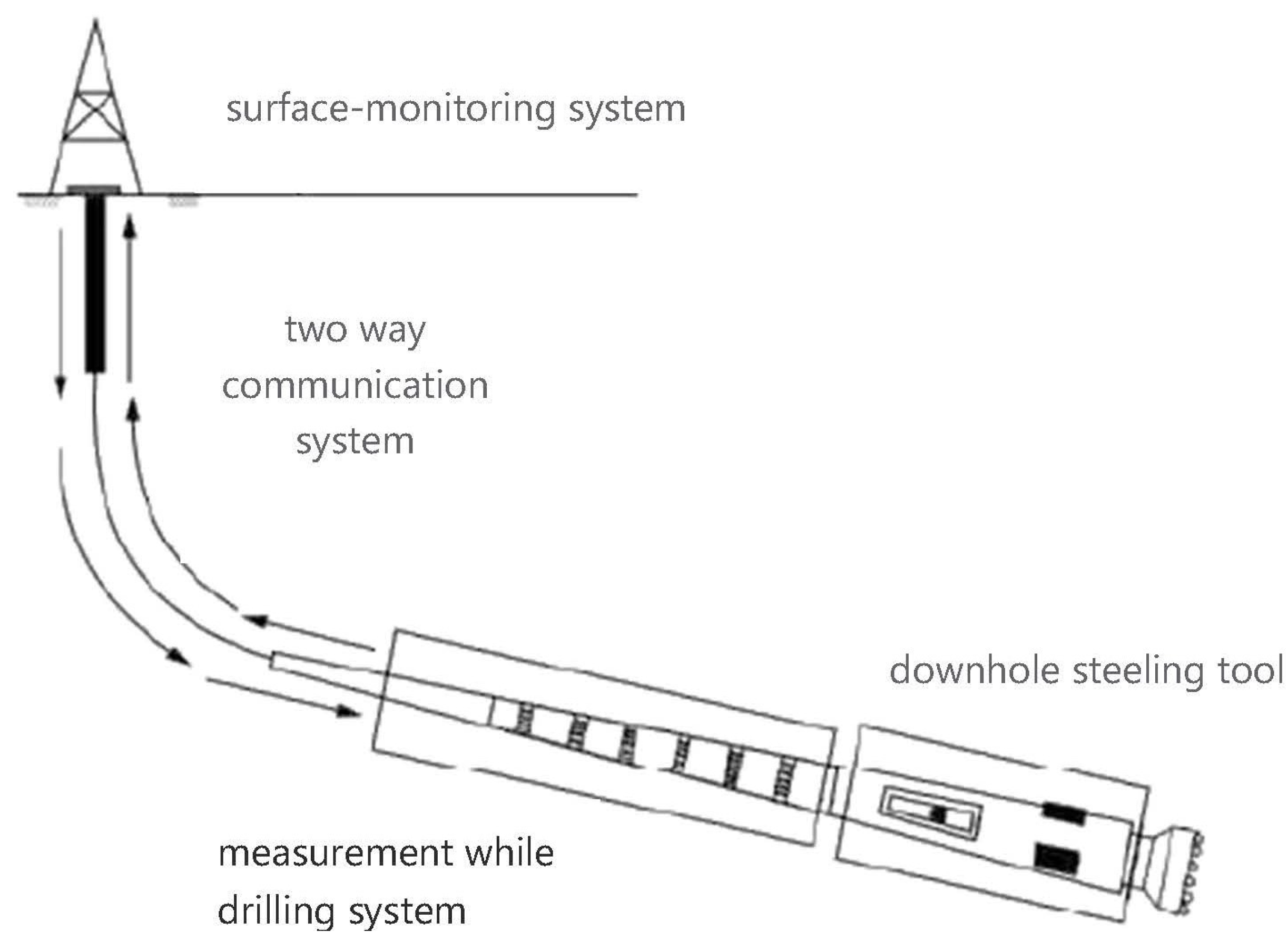
Figure 2.
Measured well inclination and tool face angles of a well in western of Sichuan, China.
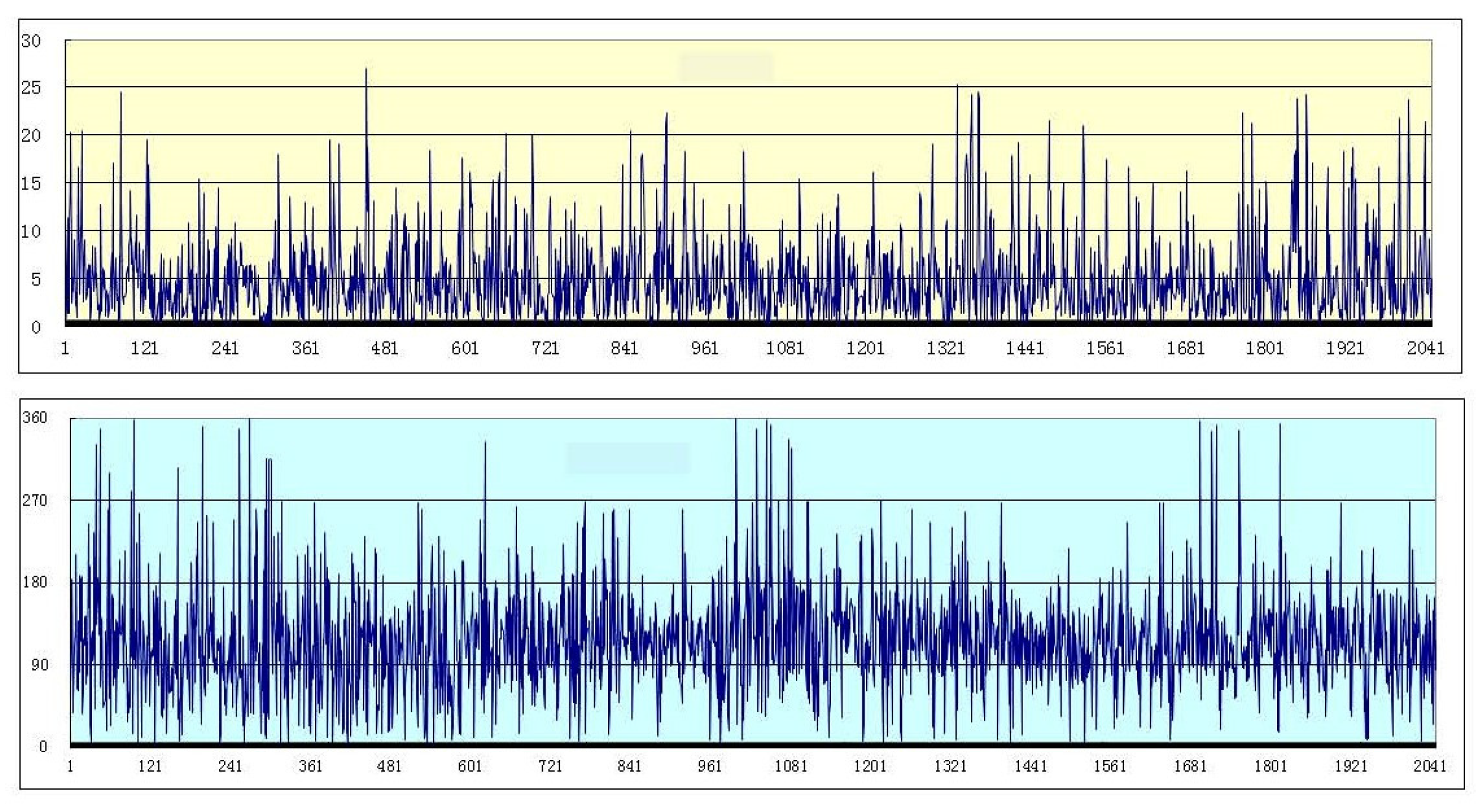
Figure 3.
Schematic diagram of multi-sensor combination measurement.
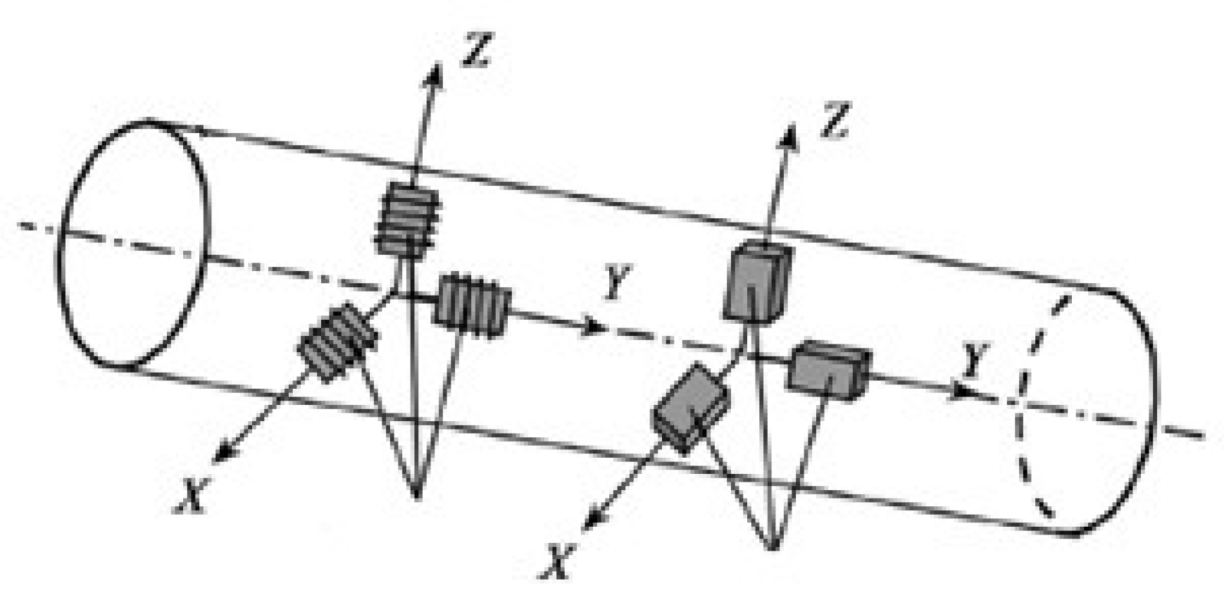
Figure 4.
Measured components of gravity acceleration along three axis.

Figure 5.
Filtered components based on Db5.
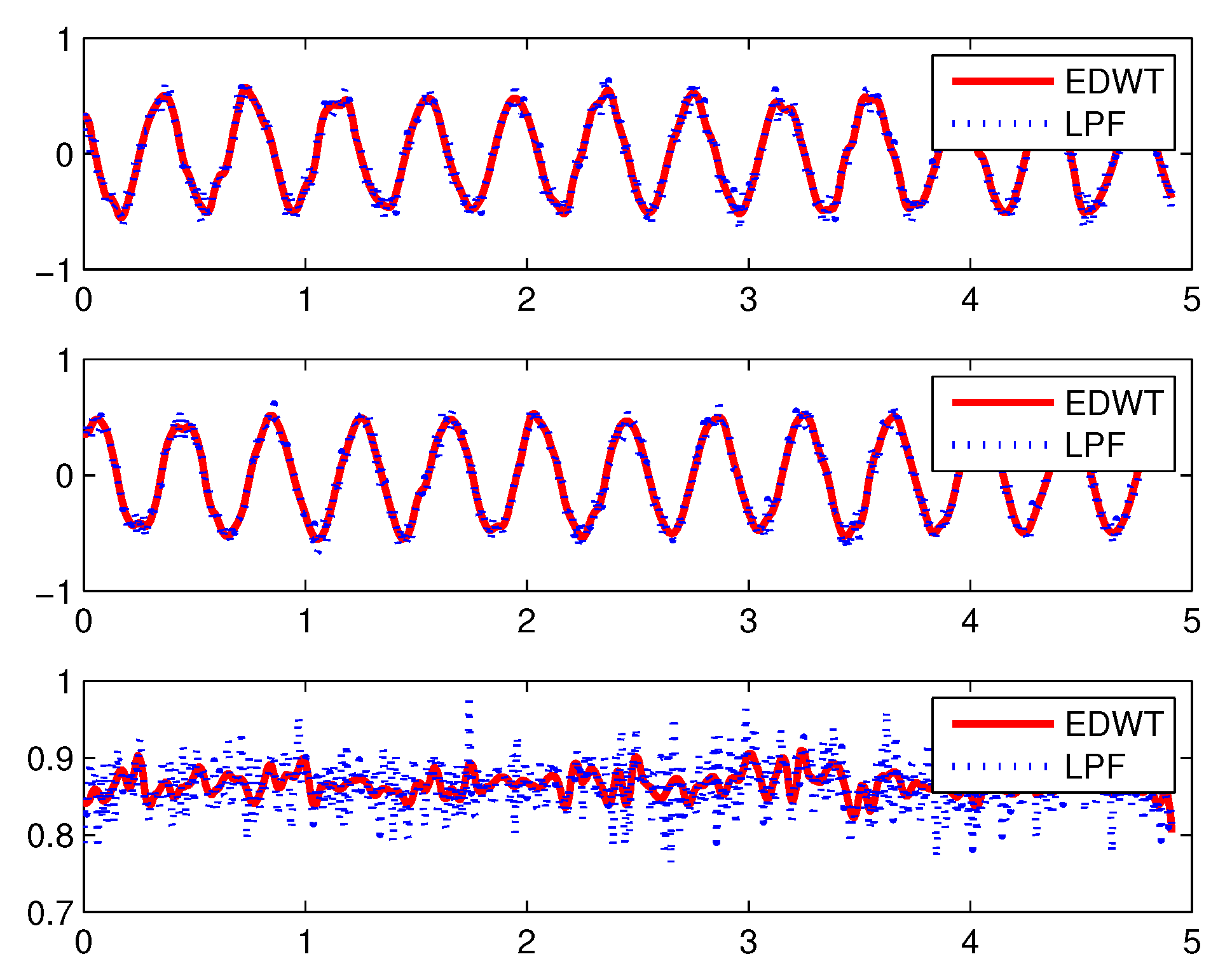
Figure 6.
Comparison of inclination angles before and after filtering.
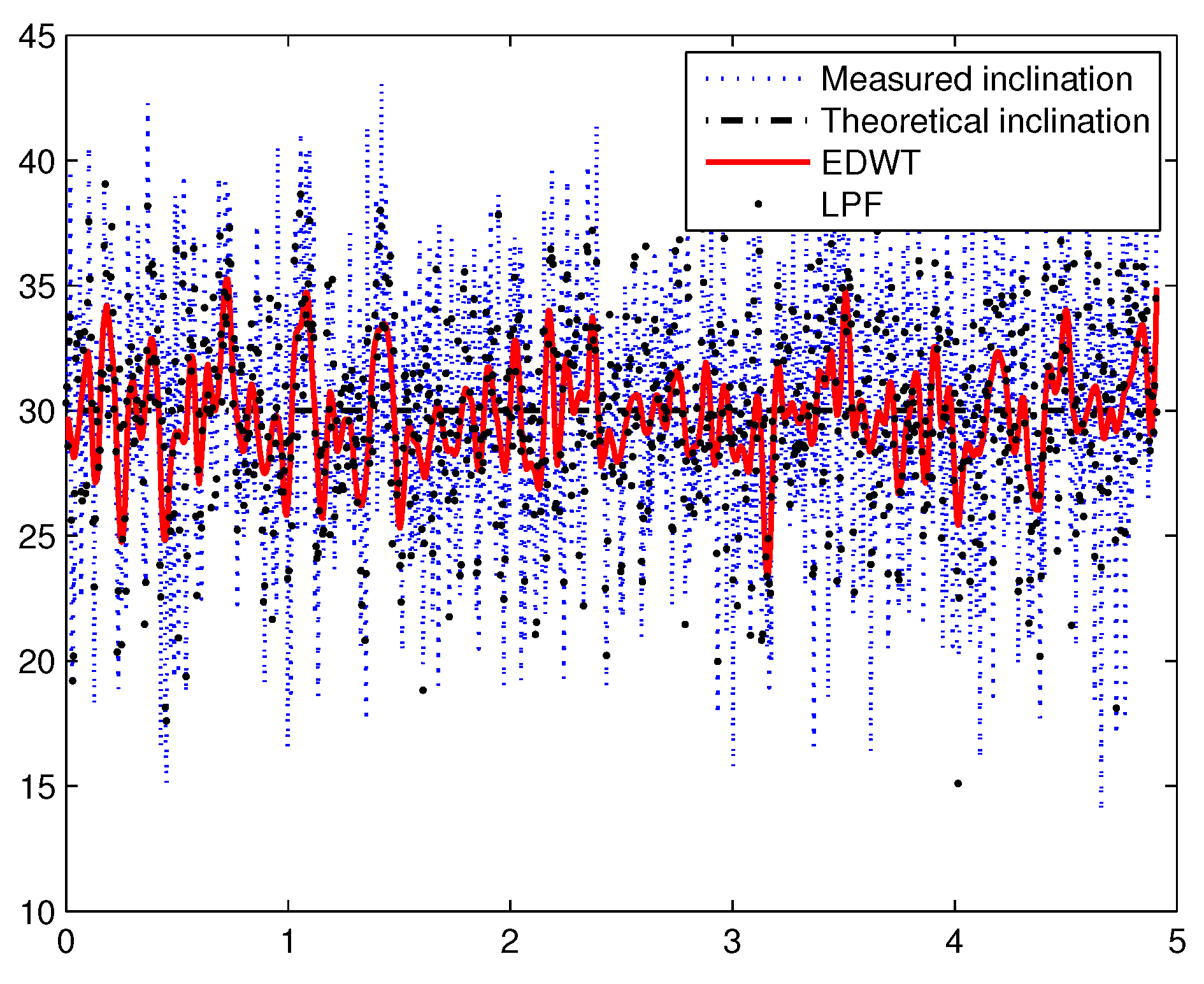
Figure 7.
Comparison of tool-face angle before and after filtering.
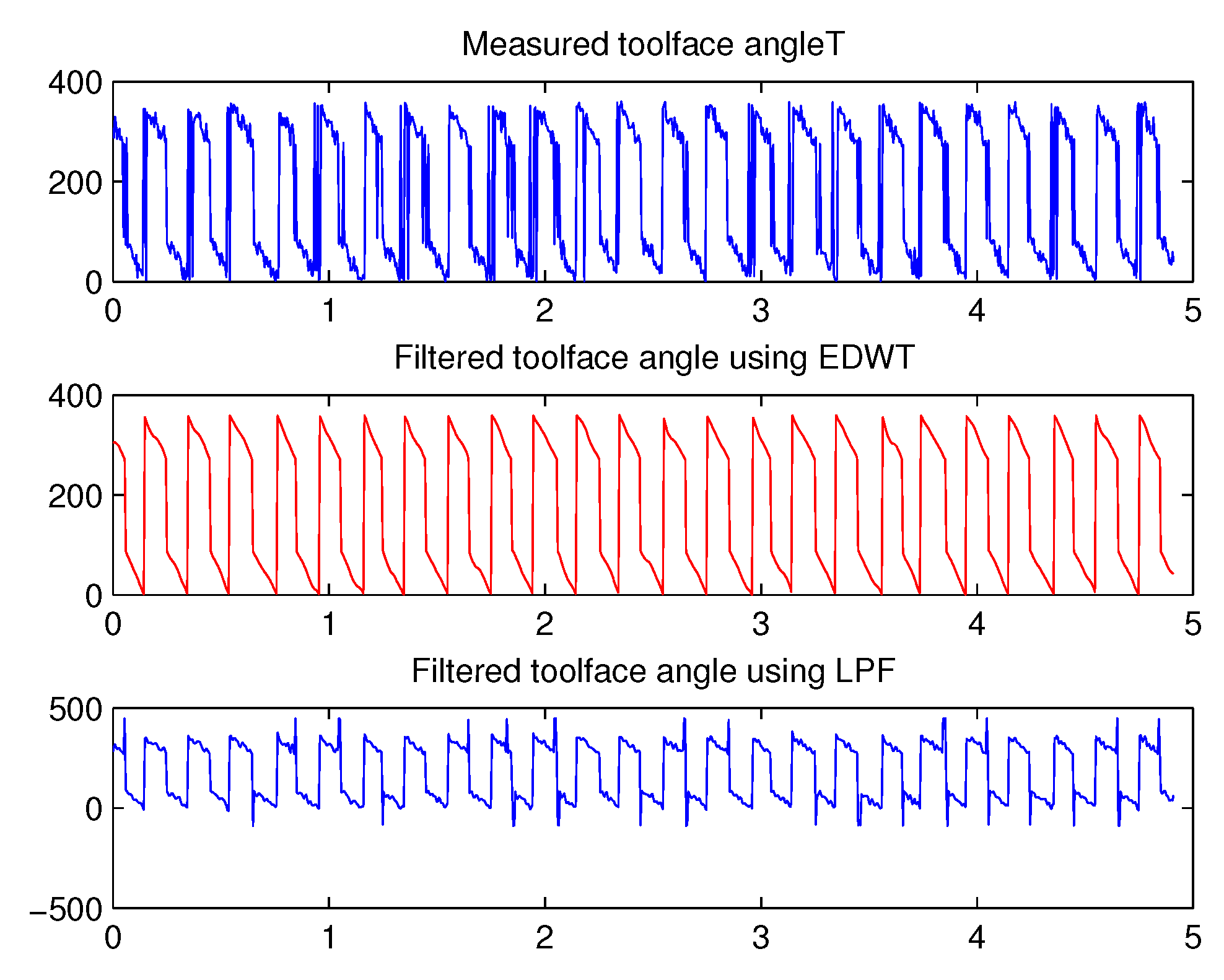
Figure 8.
Actual measurements of gravity components along three axes.

Figure 9.
Filtered measurements of gravity components along three axes.

Figure 10.
Comparison of inclination angles before and after filtering.

Figure 11.
Comparison of tool-face angle before and after filtering.
Publisher’s Note: MDPI stays neutral with regard to jurisdictional claims in published maps and institutional affiliations. |
© 2022 by the authors. Licensee MDPI, Basel, Switzerland. This article is an open access article distributed under the terms and conditions of the Creative Commons Attribution (CC BY) license (https://creativecommons.org/licenses/by/4.0/).
Share and Cite
MDPI and ACS Style
Mao, Y.; Zhong, Y.; Gao, Y.; Wang, Y. A Weak SNR Signal Extraction Method for Near-Bit Attitude Parameters Based on DWT. Actuators 2022, 11, 323. https://doi.org/10.3390/act11110323
AMA Style
Mao Y, Zhong Y, Gao Y, Wang Y. A Weak SNR Signal Extraction Method for Near-Bit Attitude Parameters Based on DWT. Actuators. 2022; 11(11):323. https://doi.org/10.3390/act11110323
Chicago/Turabian StyleMao, Yanhui, Yongmin Zhong, Yi Gao, and Yuelong Wang. 2022. "A Weak SNR Signal Extraction Method for Near-Bit Attitude Parameters Based on DWT" Actuators 11, no. 11: 323. https://doi.org/10.3390/act11110323
Note that from the first issue of 2016, this journal uses article numbers instead of page numbers. See further details here.