1. Introduction
Cardiac pacemakers are a type of implantable medical device that can be used to treat a heart condition causing irregular heartbeats, arrythmia [
1]. Arrythmia may cause a heartbeat that is too fast, too slow, or with irregular, uncoordinated heart contractions. These conditions may cause poor blood circulation and increases the risk of stroke and heart failure. Once implanted in an individual, the pacemaker can detect a patient’s heartbeat pattern and will deliver periodic electric stimulation to the heart if it detects abnormal behaviour [
2]. Pacemakers typically have a battery life of around eight to 12 years and surgical intervention is required to replace the device once the battery is depleted, increasing healthcare costs and introducing potential post-operative complications such as infection [
2,
3].
A potential solution to prolong or remove the battery entirely from the pacemaker is with energy harvesting technologies that can harness energy from the body or environment. Previous research on various energy harvesting devices using animals or humans as the energy source has been conducted and reviewed [
4,
5]. One key area of research for biological energy harvesting is through the use of a piezoelectric energy harvester (PEH) that uses materials which can generate a voltage when a mechanical strain is applied [
6]. Examples of the potential uses of piezoelectric devices for energy harvesting from biological sources includes harvesting energy from walking [
7,
8,
9], breathing [
10], and the use of piezoelectric fabrics for general human motion [
11].
Several studies have been done using an energy harvesting device that attaches onto the heart surface to harvest energy from distension of the heart [
12,
13]. Dagedeviren et al., worked on a flexible PEH that used lead zirconate titanate (PZT) as the piezoelectric material to generate power from the distention of the heart, lungs, or diaphragm [
13]. Hwang et al., developed a similar device using a crystalline (1-x) Pb(Mg1/3Nb2/3)O3–xPbTiO3(PMN-PT) piezoelectric material that was able to harness energy from heart distension and perform the tasks of the pacemaker [
12]. A PEH design proposed by Li et al., used PMN-PT to harness energy from the compression forces between the heart and the pericardial sac to power a powered pacemaker [
14]. Refs. [
12,
14] A major concern with many of these designs is that it requires specialized procedures in open the chest cavity for installation of the energy harvester, leading to a low chance of these devices advancing to human clinical trials as the risks outweigh the benefits.
Other studies have looked into attaching various piezoelectric energy harvesting structures onto the pacemaker lead wire to reduce the need for extra procedures [
15,
16,
17], but the bulky size of these designs increases the difficulty of lead wire implantation and may increase the chance of post-operative complications. The helical design proposed by Dong et al., is small compared to the other pacemaker lead wire energy harvesters [
15], but the helical structure is unable to effectively capture energy from bending due to the cancellation of some of the charges as the helical structure undergoes simultaneous tension and compression at different areas of the structure. Karami et al., and Ansari et al., looked into replacing the batteries of the pacemaker with a PEH to harvest energy from chest motion, but the removal of the battery altogether introduces a risk of device failure if problems arise in the PEH, whether that be from insufficient power generation or fatigue failure of the PEH structure [
18,
19].
Here, we investigate a PEH integrated into the lead wire that harnesses energy from heart motion that causes bending in the lead wire. The piezoelectric material is integrated into the lead wire to eliminate any additional procedures required for implantation of the device. The proposed design uses polyvinylidene fluoride (PVDF) as the piezoelectric material. This polymeric piezoelectric material has lower piezoelectric coefficients compared to traditional piezoceramics or single-crystal piezoelectric materials [
20], but allows for greater flexibility and lightweight that can better allow it to bend with the motion of the lead wire [
21,
22]. The design was modelled using finite element analysis in COMSOL Multiphysics
® v. 6.0 (COMSOL AB, Stockholm, Sweden) and verified with experimental testing. A block diagram schematic of the methodology is shown in
Figure 1.
This paper discusses a preliminary study that investigates if power generation from the proposed design is enough to power a pacemaker based on a power consumption of 1 μW [
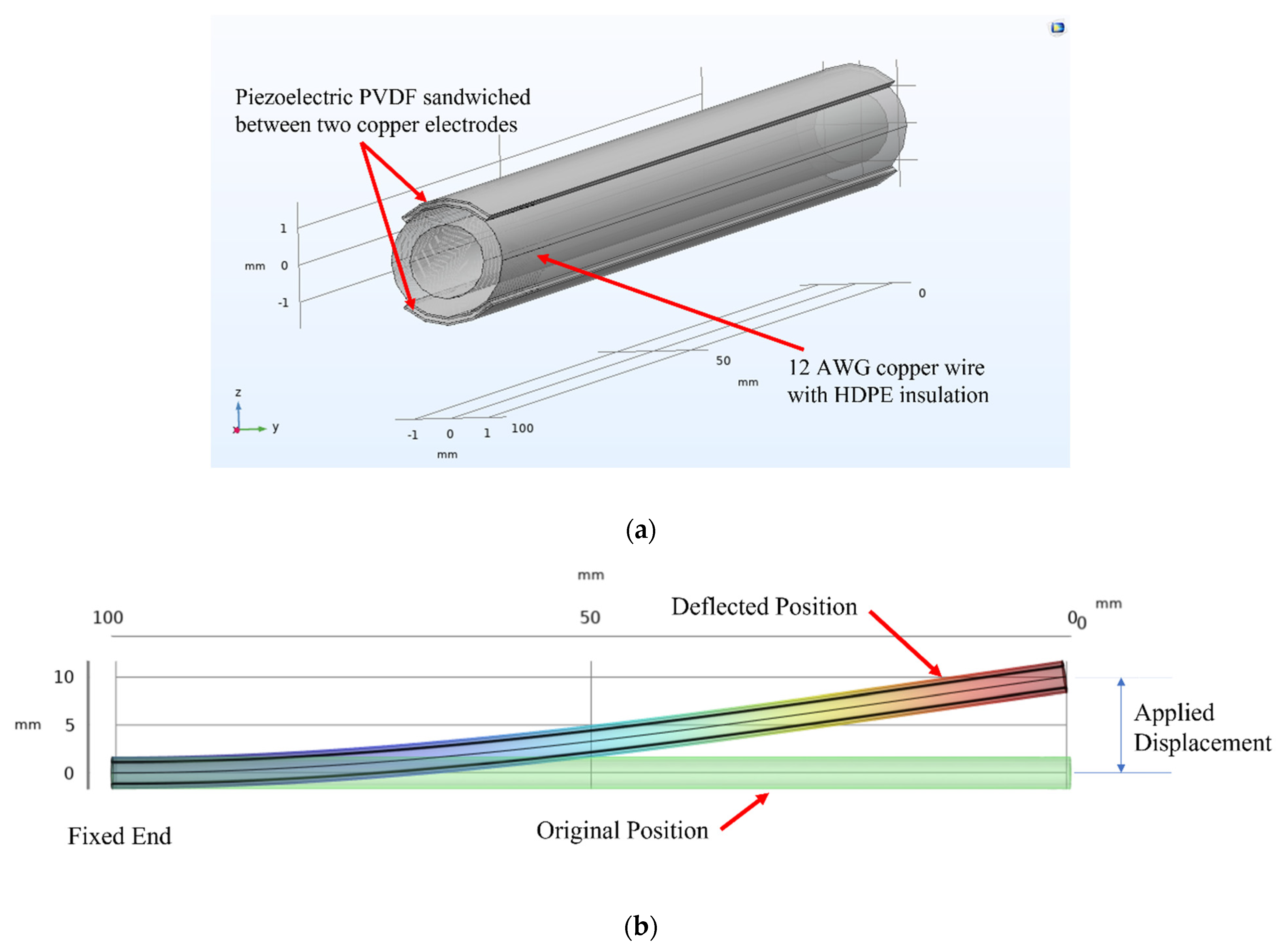
18]. In the body, the pacemaker lead wire is anchored at the point where it enters the vein and fixated to the inner wall of a beating heart, as shown in
Figure 2a. Simulation is performed by considering the structure as a cantilever beam fixed at one end and with a displacement at the other end to model the displacement of the lead wire tip when the heart beats. As the heart contracts and expands as it beats, the lead wire bends, as shown in
Figure 2b. By placing a piezoelectric energy harvester in the lead wire, the energy harvester is able to harness the bending stress and convert it to energy to power the pacemaker.
2. Materials and Methods
2.1. Materials
110 μm thick PVDF film with sputtered Cu/Ni electrode (PolyK, State College, PA, USA) was purchased for use as the PEH material, copper foil electrical tape (Lamart Corporation, Clifton, NJ, USA) was used as the piezoelectric electrodes, high density polyethylene (HDPE) insulated copper wire 12 AWG (Consolidated Electronic Wire and Cable, Franklin Park, IL, USA) was used as a substitute for the pacemaker lead wire to decrease prototyping costs. Laboratory Parafilm™ was used to attach the piezoelectric structure to the pacemaker lead wire.
2.2. Piezoelectric Energy Harvester Pacemaker Lead Wire Design
Figure 3 shows a schematic of the design of the PEH device integrated into a pacemaker lead wire. Strips of PVDF thin films are used as the piezoelectric material and sandwiched between two copper electrodes. The strips are placed on the top and bottom surfaces of the pacemaker lead wire. A polydimethylsiloxane (PDMS) encapsulation can be applied to ensure biocompatibility in future biocompatibility studies but should not be required if the PEH is integrated into the existing pacemaker lead wire insulation material. This design allows the piezoelectric PVDF material to operate in its
mode during bending of the lead wire.
2.3. Prototype Assembly
A prototype of the PVDF piezoelectric pacemaker lead wire energy harvester was manufactured in-house with materials described in
Section 2.1. The 110 μm thick PVDF with sputtered electrode sheet was cut into 10 cm long and 2 mm wide strips. For prototyping, only one strip (monolayer) was used on the top surface of the pacemaker lead wire. Copper electrical tape was adhered to opposing surfaces of the PVDF film to form a sandwich structure, and single-strand copper wires were soldered onto opposite sides of the sandwich structure to serve as contacts for electrical measurements. The sandwich piezoelectric strip was placed on top of the pacemaker lead wire and then paraffin wax film was wrapped around the piezoelectric sandwich and pacemaker lead wire to hold them together.
2.4. Finite Element Analysis Method
A finite element analysis (FEA) was conducted using COMSOL Multiphysics
® v 6.0 (COMSOL AB, Stockholm, Sweden). A 10 cm long section was modelled in the geometry shown in
Figure 4a. The surfaces on one end were treated as fixed, the other end was subject to a time-dependent displacement to model the motion of the heart, the boundary condition is shown in
Figure 4b. The voltage and power outputs during each heartbeat motion were investigated. To save on computational resources, a 10 cm length pacemaker lead wire is modelled in FEA and compared with a 10 cm prototype for validation.
The copper wire 12 AWG was modelled as a cylinder with another cylinder surrounding it as the HDPE wire insulation material. The inner cylinder diameter is 2 mm, and the insulation cylinder diameter is 3 mm. The piezoelectric sheets consist of a 110 μm-thick PVDF layer sandwiched between two copper electrodes each with a thickness of 8.89 μm. The piezoelectric sandwich structure has a width based on a 90 angle cut of the outer diameter. The inner electrodes were grounded, and the outer electrodes were used as terminals in the electrostatics study of COMSOL to measure the voltage through the piezoelectric material. A wire length of 10 cm was used to save computation resources. The Young’s modulus used for the inner copper wire, HDPE insulation, copper electrodes, and PVDF were, respectively, 90 GPa, 1 GPa, 110 GPa, and 2.5 GPa. For the piezoelectric PVDF, the manufacturer reported piezoelectric constants of , , and a relative permittivity of . For simulation, and were both assumed to be .
For the purpose of using the prototype to validate the FEA model, a single piezoelectric layer was modelled. Upon validation of the FEA with experimental data, further studies were conducted with two piezoelectric strips (bilayer) connected in series and with increasing magnitudes of tip deflection to determine if the design can output the desired 1 μW power.
3. Results and Discussion
3.1. Experimental Results
The assembled monolayer PEH pacemaker lead wire prototype was connected to an oscilloscope (Tektronix MDO3024) with an internal load resistance of
to analyze the output voltage with a test setup as shown in
Figure 5.
The output voltage from this prototype is used to validate a finite element model to determine whether or not FEA is able to provide accurate results for power and voltage outputs. To save on computational resources, a 10 cm length pacemaker lead wire is modelled in FEA and a 10 cm prototype is manufactured. One end of the structure was clamped and finger tapping was used to displace the tip by 1 mm at a frequency of approximately 70 bpm over a span of four seconds. Here, finger tapping is used as the method of excitation. Finger tapping serves as an inexpensive tool to cause small excitations at a frequency close to that of the human heartbeat. The exact magnitudes of the voltages are not critical to the success of this paper, but so long as the values provided by the finite element simulation are reasonably close to that of the experimental values, then the FEA prediction will be deemed as validated.
When the tip was displaced, the voltage output was negative. The output voltage was recorded and is shown in
Figure 6. Upon releasing the device tip to return to its original position, the voltage output jumped to a positive value. The maximum and minimum output voltage magnitudes are 0.046 V and −0.091 V, respectively.
3.2. Finite Element Validation
A finite element model was simulated as a monolayer PEH to compare with the experimental result. The geometry is shown in
Figure 4a with a single piezoelectric layer on the top surface. The dimensions and material properties are described in
Section 2.3. The periodic triangular-shaped displacement shown in
Figure 7a was applied on the tip of the cantilever PEH pacemaker lead wire structure. From this displacement, a time-dependent study was performed to characterize the voltage output from the piezoelectric monolayer. The plotted voltage output from the device is shown in
Figure 7b with the displacement function. When the tip was displaced, the piezoelectric material outputted a negative voltage. When the tip was returned to its resting position, the voltage jumped to a positive value. The maximum and minimum voltage outputs from the FEA are
V and have the same magnitude.
To validate the FEA results, the experimental output was compared to the FEA results. A plot with both voltage outputs is shown in
Figure 6. As stated previously, the maximum and minimum voltages magnitudes for the experimental prototype are 0.046 V and −0.091 V, respectively, and the maximum and minimum voltages magnitudes for the FEA simulation are
V. The peak-to-peak voltage output from the experiment and simulation are, respectively, 0.137 V and 0.126 V.
The prototype was able to reach a larger initial voltage output magnitude when the cantilever tip was displaced compared to the FEA simulation. However, when the cantilever tip was allowed to return to its initial position, the FEA simulation outputted a larger voltage magnitude compared to the prototype. The discrepancy is likely caused by the inconsistencies in the finger tapping for the experimental model. In the experimental model, finger tapping was used to displace the tip, but the cantilever tip was allowed to return to its original position without any external load or force applied. In the finite element simulation, a waveform is used to generate the displacement that includes unloading of the cantilever tip. This difference in how the cantilever tip returns to its original position may be the cause of the discrepancy in the shape of the curves. It may also be inferred that the simulation underestimates the voltage values during the initial displacement of the cantilever structure tip. The difference in the initial peak voltage outputs may be due to the inaccuracies in finger tapping. Overall, the simulation presents a good estimation of the performance of the physical model and is considered a valid predictor of the physical prototype. Thus, FEA is used as a tool for further analysis to characterize the displacement required for the desired output power of 1 μW.
3.3. Finite Element Analysis for Required Power Generation
Further investigation was done using COMSOL Multiphysics V6.0 to determine the required tip deflection that generates the required power output. The geometry of the device used for analysis is shown in
Figure 4 with dimensions and material properties described in
Section 2.3 The same waveform shown in
Figure 7a was used with increasing displacements. The time dependent study was conducted over a span of 2 s with a cantilever length of 10 cm. Output power from the device is calculated using the expression “0.5*realdot(cir.R1_i,cir.R1_v)” in COMSOL, which calculates the alternating current (AC) power using the AC voltage and current coming from the device.
Upon reaching a displacement magnitude of 9.1 mm, the output power of 1 μW was achieved per heartbeat. A plot of the displacement and power output is shown in
Figure 8a. The voltage output from the 9.1 mm displacement is shown in
Figure 8b. The maximum and minimum voltage outputs from the series bilayer PEH pacemaker lead wire is
1.4 V. This 9.1 mm deflection is within the normal range of heartbeat amplitudes of
mm [
23].
The first cycles in
Figure 8 are different compared to the next two. This may be attributed to the use of a timestep not small enough to resolve this first cycle. However, decreasing the timesteps will increase the computational resources. It was determined that the timestep used provides a reasonable estimate for the peak power output while still providing relatively accurate predictions for the peak power output.
In order to achieve energy storage of this AC power, a full wave bridge rectifier will be required to convert the AC voltage into a DC voltage [
24]. Assuming no energy losses, this device will be able to provide sufficient energy output for powering a cardiac pacemaker. Further work must be done to quantify energy losses and impedance matching can be conducted to minimize losses.
This analysis demonstrates the ability of this piezoelectric energy harvester design to provide sufficient power output for powering a pacemaker. This PEH may also be useful in powering other implantable biomedical devices. It also gives insight into the use of moving wires to power electronic devices, such as possibly using headphone wires to charge smart phones.


