1. Introduction
In recent decades, switching hydraulics has been more and more popular for high-efficiency and fast response performance, as well as low cost [
1,
2,
3,
4,
5,
6]. However, the technology has not penetrated the marketplace, partially due to the energy loss during transition events of the valves. The more frequently the valve switches, the more energy loss it produces. Although much research has focused on switching energy loss, eliminating flowrate or pressure drop through/across the switching valve during transition events is still a challenge. It has been identified that such energy loss originates from transition times, pressure drops across and throttled flow through the switching valves, fluid compressibility, hysteresis in the accumulator bladder, fluid friction, and leakage [
7]. Among them, the transition time is dominant (about 60%) [
8,
9]; other significant losses in the system are generated by compressibility (20%), full open throttling (19%), and leakage (1%). According to a comparison of the numbers, transition time and throttling result in 79% energy loss in total. James D. Van de Ven presented volumetric efficiencies that ranged from 51% to 95% in three different circuits, which shows that the dominant power loss is due to throttling through the ports of the switching valve during valve transition events [
10]. Thus, the focus to improve the efficiencies of switching hydraulic actuators is to explore solutions to attenuate energy consumption during transitions of valves.
Energy loss is the production of flowrates and pressure drops; therefore, it is possible to reduce power loss by decreasing either flowrate through or pressure drop across the valve, which is inspired by “Soft Switching Technology” in electronic technology. In recent decades, some researchers have proposed different soft switching methods to increase the efficiency of a hydraulic switching actuator. One of the methodologies is to switch off a control valve when the pressure drop across the valve is zero. In 2009, Michael B. Rannow and Perry Y. Li [
11] proposed a soft switch where a piston chamber with a spring at the back of the piston is applied parallel to the switching valve. When the switch valve is to switch off, a tank valve is switched on to accelerate the flowrate; then the tank valve is switched off; as a result, the fluid is forced to go to the piston chamber and the momentum is converted to the pressure of the piston chamber. Once the pressure is up to the cracking pressure of the check valve parallel to the switching valve, the check valve is opened and the pressure drop across the switching valve becomes zero. Therefore, the switching valve is able to switch off with very small energy loss. By applying such a soft switching configuration, the transition and compressibility losses are reduced by 81% and total system losses by 64%. In 2017, Alexander C. Yudell and James D. Van de Ven applied a similar principle to an inertance hydraulic circuit aiming at reducing switching power loss caused by high-speed valves whose power loss is up to 44% of overall losses. Their simulation results demonstrate that the soft switching controller increases system efficiency by 42% at peak load power and extends the power delivery capabilities by 77%.
These research works indicate that soft switching technology is a potential solution for transition loss in a switching hydraulic system. However, there are some limitations for the above work. Firstly, very fast valves are needed for such a soft switch. To minimize the switching period in hydraulic switch mode circuits, the transition time of the valve is on the order of 5% of the switching period. The high-speed valve used in the research transitions in 0.8 ms and is capable of 100 Hz switching. Since a high-speed valve whose opening/closing times are as short as 0.8 ms are very expensive and difficult to obtain commercially, the application of such soft switching technologies in conditions where very fast-switching valves are used is limited.
Since 2016, S. Peng has proposed a zero-flowrate switching control technology where the flowrate through a switching valve is reduced to zero and then the valve is switched off [
12,
13]. In the work, a hydraulic resonator is applied to regulate flowrates to zero and small pressure waves from a normal piston pump are used as the excitation. Since the base frequency of the pressure waves is about 113 Hz, the frequency of excited flowrate waves is also about 113 Hz, which means the transition time of the switching valve should be smaller than 8.8 ms (one period for 113 Hz). In the above work, the system efficiency is improved by 89% with fast-switching valves whose transition time is 2 ms. The transition time of 2 ms still makes a valve very expensive and a great limitation of applications; in addition, to make the resonator work, the capacitance and inductance should be designed carefully to match the natural frequency of the resonator; thus, the dimensions of the resonator can be too large to limit the application of this technology.
In this paper, an improved zero-flowrate switching method is proposed for improving the efficiency of hydraulic switching actuators. The control scheme consists of two control branches: one is the main control line, and the other is the auxiliary control line. The flowrate-regulation function is achieved by the capacity in the auxiliary line with the help of resistance and inductance in two branches. As a result, the proposed method does not require the natural frequency of the capacity to match a specified frequency. The suggested solution improves the energy efficiency of a hydraulic switching actuator by reducing throttling loss during transitions of the valves. A thorough analysis is carried out numerically against a hard-switching actuator in order to confirm the effectiveness and efficiency performance of the suggested method. In conclusion, this paper’s contribution consists of the following.
- (1)
Proposing an improved zero-flowrate switching method for a hydraulic switching actuator. The suggested approach is created as an alternative to a hard-switching controller, to achieve higher efficiency in applications that allow relatively slower switching valves.
- (2)
The improved control method utilizes a capacity to regulate flowrates through the lines; thus, the dimension of capacity can be more flexible because resistance and inductance in the lines help to further adjust flowrates as required. While in the previous method, a hydraulic resonator that consists of a capacitance and inductance was applied, the frequencies of the capacitance and inductance should match the natural frequency of the resonator, which can make the volume of capacity too large, or the inductor too long, or inappropriate for the application.
- (3)
The characteristic of the capacity with different input pressure signals is analyzed and the effectiveness of applying a capacity to regulate flowrates in a hydraulic switching actuator in desired conditions is validated numerically. An efficiency improvement is confirmed numerically with lumped models of resistance, inductance, and capacitance.
The focus of this paper is on presenting a high-efficiency hydraulic actuator by applying a novel mechanism to enable zero-flowrate switching in hydraulic switching actuators. In
Section 2, the general principles of zero-flowrate switching technology are presented. Next, the mechanism of an improved zero-flowrate switching controller is explained in
Section 3. To validate the mechanism, the simulation models are developed in
Section 4 to explore the feasibility of this novel method.
Section 5 presents a complete model of an improved zero-flowrate switching actuator, and the simulation results are presented in
Section 6 and discussed in
Section 7.
Section 8 provides the concluding remarks.
2. Concept of Zero-Flowrate Switching Technology
Zero-flowrate switching technology is a switching methodology where flowrate across the control valve is reduced to approximately zero when the valve is switched off. This concept is inspired by the zero-current switching method in electronic engineering [
14]. The methodology aims to decrease transition losses by reducing flowrates through the switching valve dramatically during a transition event.
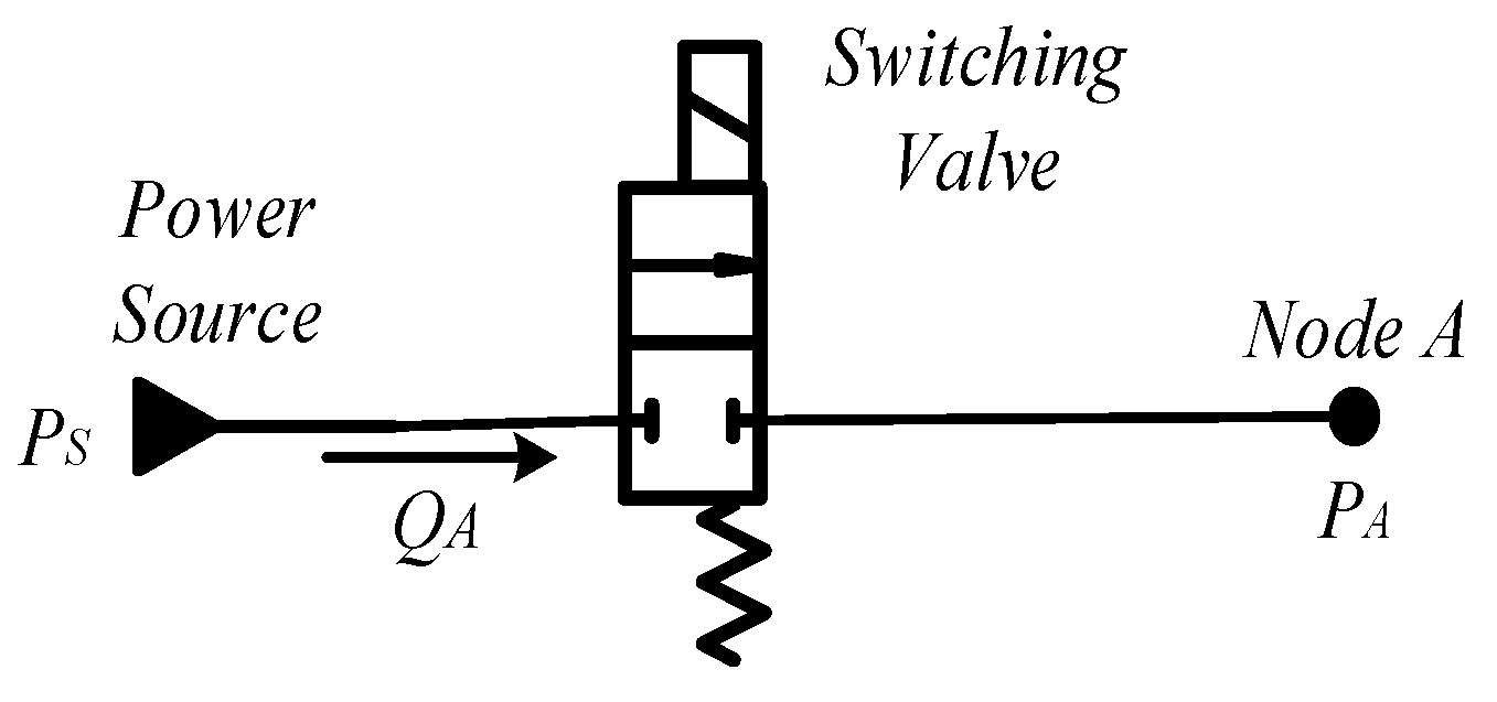
As shown in
Figure 1, a switching valve is used to switch on/off the control line. Since it takes some time for the valve spool to move from the totally open position to the totally closed position, there must be some flowrates and pressure drops during a valve transition event. As shown in
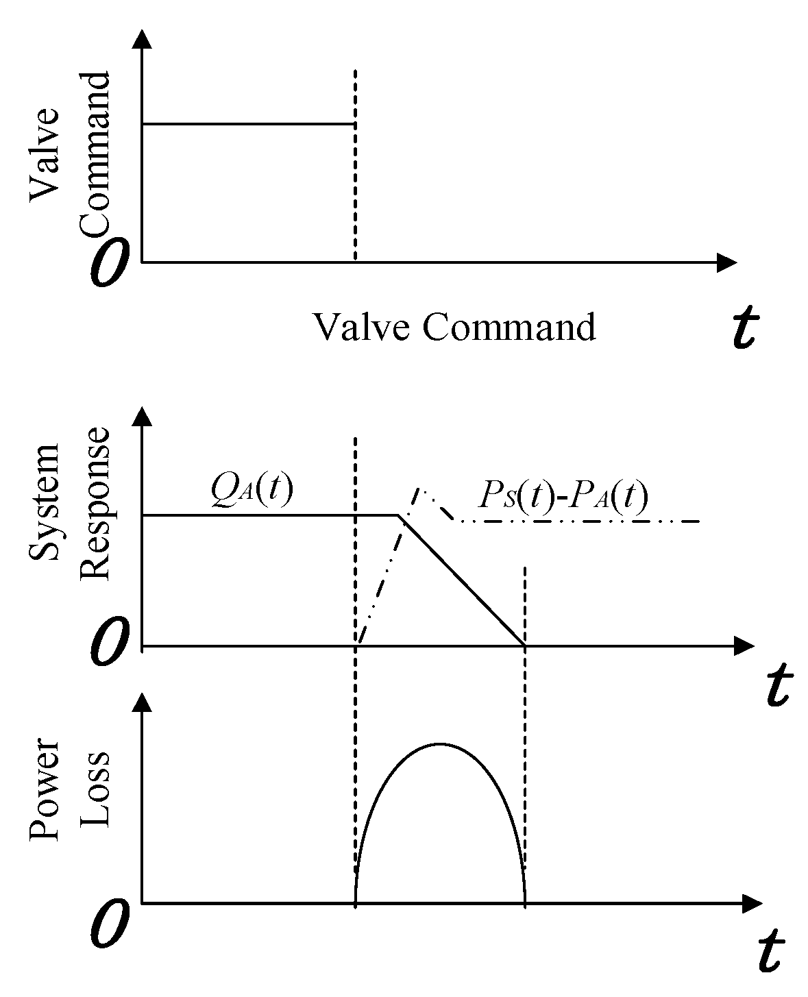
Figure 2, flowrates and pressure drops lead to certain energy loss. The more frequently the valve switches, the larger the energy losses are. Thus, it is important to reduce transition loss for such a switching valve control line.
As explained in
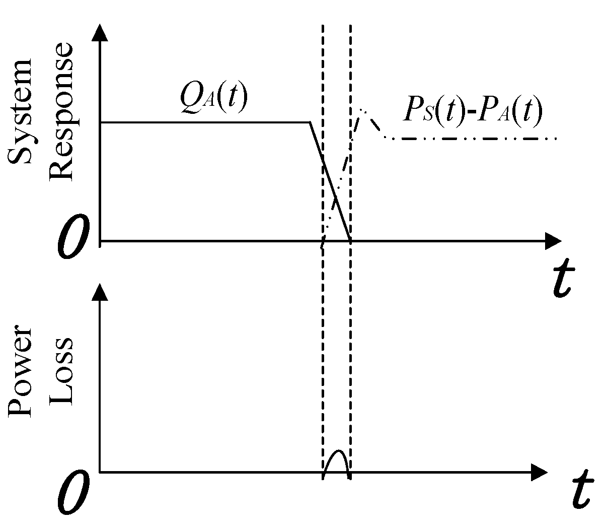
Figure 2, power loss during valve transition is the production of pressure drop and flowrate; thus, one potential solution to reduce switching power loss is to actively reduce the flowrate to approximately zero before the switching-off process starts. As shown in
Figure 3, the flowrate through the valve is already small enough when the valve starts to switch off; thus, the transition power loss is greatly reduced compared to that in
Figure 2.
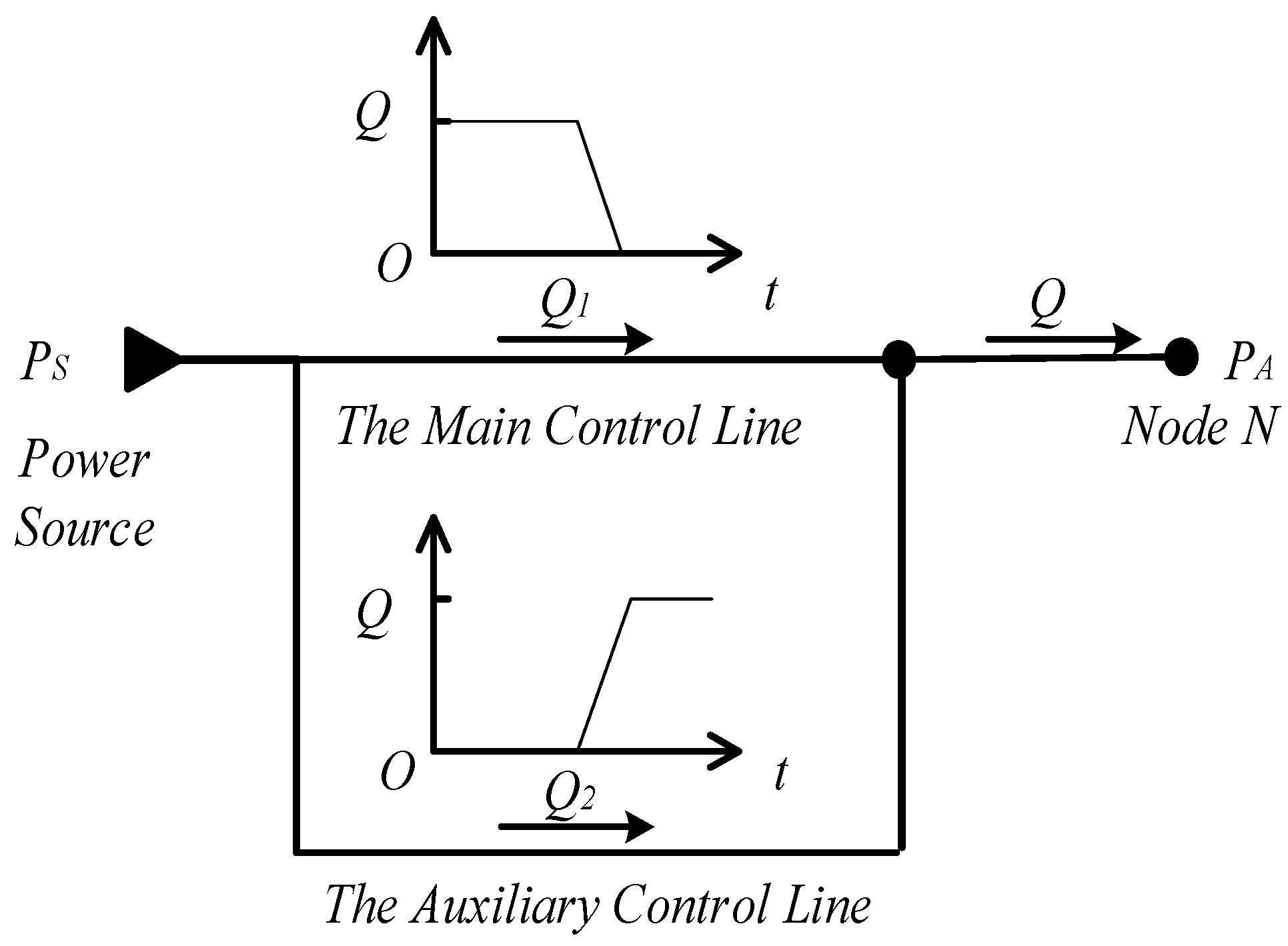
In an existing zero-flowrate switching controller (as shown in
Figure 4) developed by S. Peng [
6,
7], two parallel control lines are designed to regulate flowrates through the lines: a main control line is in charge of switching on/off the control line between the power source and node N; an auxiliary control line assists regulating the flowrates through the two lines and realizing a zero-flowrate switching controller. When there is a need to switch off the control line, instead of switching off the control line directly, the auxiliary control line is switched on to connect a hydraulic resonator parallel to the main control line. Therefore, flowrates through the main control line will be reduced when the resonant flowrates of the auxiliary line increase; the main control valve can be switched off when the flowrate is reduced to a minimum. After the main control valve is switched off, the flowrate before the capacity keeps resonating until it drops to zero; then it is time to switch off the valve in the auxiliary control line. In the end, all the valves in this hydraulic system are switched off at minimum flowrates. Transition power losses have been greatly reduced.
In the above research work, a hydraulic resonator in the auxiliary control line, consisting of a hydraulic capacity and a hydraulic inductance, produces harmonic flowrate waves at resonance frequency
where
C is capacitance;
L is the inductance; and
ω is the angular frequency of the resonator. The flowrate waves minimize the flowrate (approaching zero) at some moments when they are best to switch off the switching valve.
This design offers the feasibility to reduce transition power loss while it is only suitable for the switching valves whose transition times are no more than 2 ms. Considering the high cost and difficulties of obtaining such valves, it is practical to apply those hydraulic controllers with normal switching valves. In the following section, the authors are going to propose an improved zero-flowrate switching controller where the transition time of the switching valve is as large as 20 ms.
3. An Improved Zero-Flowrate Switching Controller
To better regulate flowrates through the lines and effectively reduce switching power loss with valves whose transition times are longer than those in the previous research work, a novel capacity-based solution is proposed. The improved zero-flowrate switching controller, shown in
Figure 5, utilizes capacity to absorb a large flowrate and regulate flowrate through the lines. Similar to the previous zero-flowrate switching controller in [
6,
7], there are two parallel control lines: the main control line and the auxiliary control line. In the schematic presented in
Figure 5, conduit 1 is a lumped model which represents total resistance through the main control line; conduit 2 is a lumped model that represents total inductance/resistance through the auxiliary control line; capacity
C is a lumped model representing all the capacity through the auxiliary control line. Capacitance and inductance through the main control line are minor for system performance and ignored in the models of this paper. The load is simplified as an orifice in this system.
The capacity in the auxiliary control line has two independent ports: an inlet connected with power source and an outlet connected to load direction, which leads to independent control of flowrates at inlet/outlet ports. In an ideal capacity model, the pressure differential at the inlet makes flowrate changes as the following equation explains.
where
Ps is the pressure of the power source,
Qout is the flowrate into the load, B is the bulk modulus,
vol0 is the volume of the capacity, and
t is the time. By inputting a proper pressure difference at the inlet of capacity, there will be a flowrate increase through the auxiliary control line, and accordingly a flowrate drop through the main control line, as
Figure 4 explains; at the same time, the flowrates at the outlet of capacity are stabilized at zero by the inductance of conduit 2 so that enough transition time for valve 3 is guaranteed. The resistance ratio of conduit 1 and conduit 2 is related to the flowrate ratio of the two lines. By designing proper resistance for the two lines, desired flowrates can be obtained for both lines.
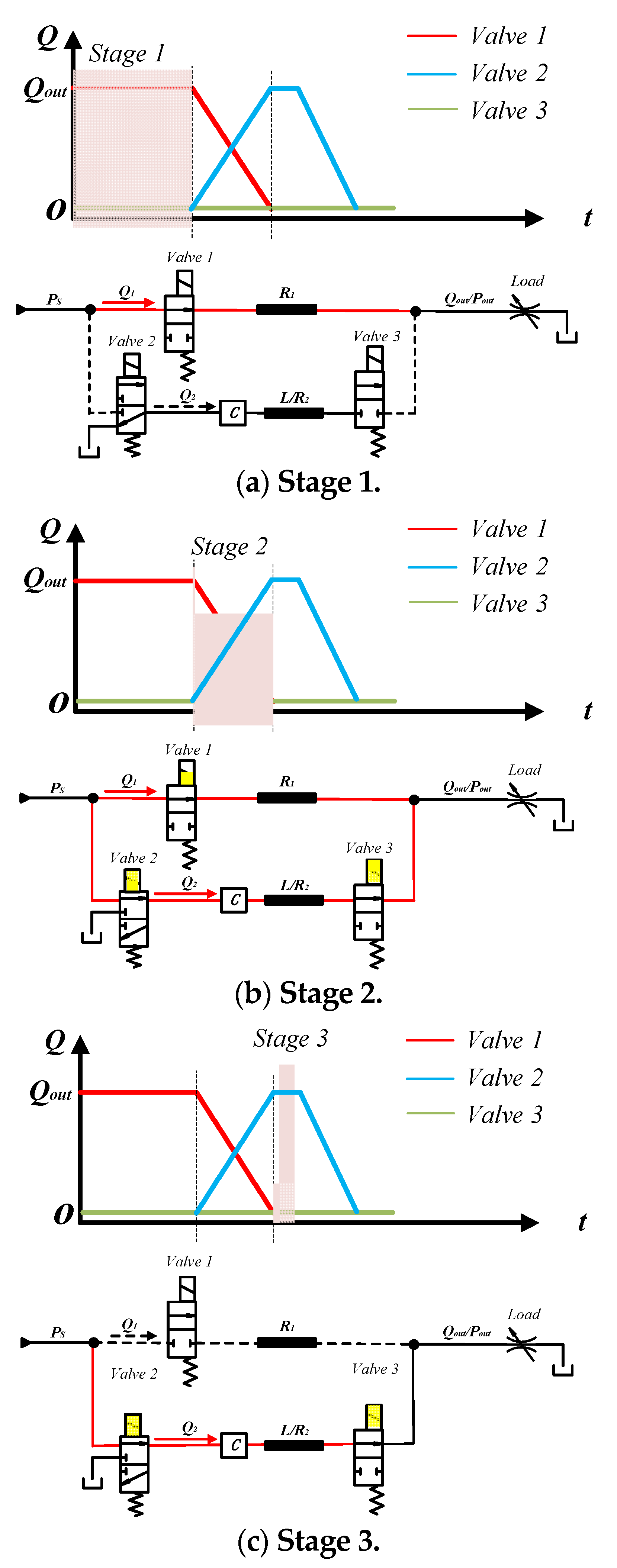
Stage 1
This is a working stage. As presented in
Figure 6a, the main control line is connecting the power source to the load; the auxiliary line is disconnected; and the system is actuating the load. The capacity is connected with the tank and the inlet pressure is equal to the tank pressure.
Stage 2
When there is a need to stop the load, stage 2 is started: valve 2 and valve 3 are switched on to connect the capacity and conduit 2 parallel to the main control line. Switching from the tank to the power source at the inlet of the capacity makes a large pressure difference to the capacity, which fulfills the condition for the flowrate at the inlet of capacity to accelerate. As a result, the flowrate through the auxiliary line rises up until the flowrate through the main control line drops to a minimum. Since the capacity is large enough and there is an inductance at the outlet of the capacity, the flowrate through valve 3 stays at zero for some time, which can be long enough for valve 3 to switch off at zero flowrate.
Stage 3
At the beginning of this stage, the flowrate through the main control line has already been at a minimum, when the best time to switch off valve 1 is. After valve 1 is switched off, almost all the flowrate from the power source goes to the capacity. Due to the effect of inductance, the flowrate through valve 3 stays at zero in this stage.
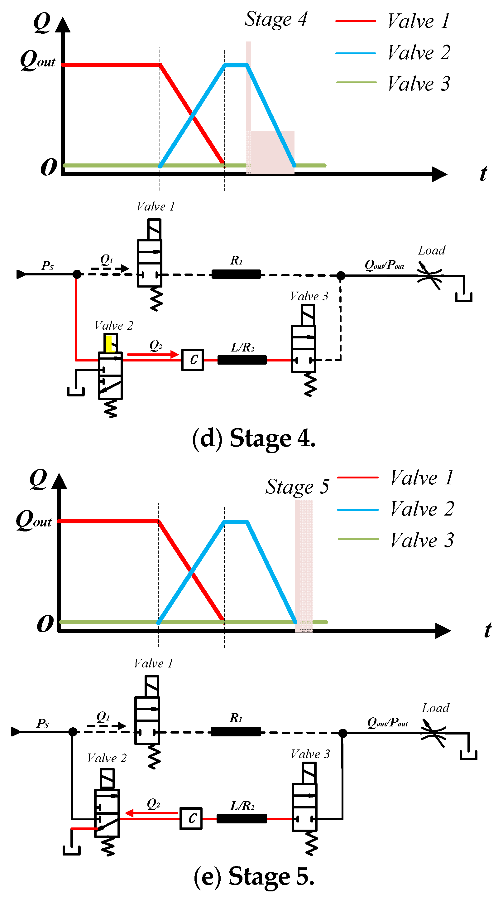
Stage 4
After valve 3 is switched off, both the main control line and the auxiliary control line have been disconnected; at the same time, the inlet port of capacity is still connected with the power source. It takes some time for the capacity to finish relieving and the inlet pressure to achieve stabilization.
Stage 5
When the inlet pressure of the capacity has achieved stabilization, the inlet flowrate (which is also the flowrate through valve 2) becomes zero, accordingly; then valve 2 can be switched off at zero flowrate. As
Figure 6e shows, valve 2 now is connected to the tank, allowing the capacity pressure to be relieved, which is to make sure there will be enough of a pressure difference for the next switching-off process. The working states of the three valves in five stages are presented in
Table 1.
4. Validation of the Improved Flowrate Switching Method
In this paper, the commercial software AMESim 2021.1 is used to build models for hydraulic systems. Before the presentation of a complete hydraulic system, AMESim submodels are introduced; with these submodels, the characteristics of a capacity to generate a flowrate pulse with step pressure input are investigated, based on which the performance of a switching control line with two parallel branches (one is the main control line and the other is the auxiliary line) excited by step input pressure is analyzed. The results show the feasibility of the mechanism of a zero-flowrate switching technology. With these validations, an optimization design of a zero-flowrate switching actuator is obtained and a complete actuation model will be built and investigated for power loss and efficiency performance in the next section.
4.1. AMESim Submodels for Hydraulic Conduits
Ideally, the inductance conduit is purely an inductive element. However, the friction effect existing in a physical tube yields resistance; the compressibility of the fluid makes capacitive effects. Capacitance and resistance are distributed along the conduits throughout a physical system. In this simulation, capacitance, resistance, and inductance through the conduits are modeled with different lumped submodels according to the main effects of the components. The AMESim submodels of hydraulic conduits applied in this work are HL0000 (C), HL0000 (C-R), HL002 (R-C), HL002 (R-C-R), HL0002 (R-C-R), and HL0040 (C-IR-**-C-IR). The description of these submodels can be checked in the help file from the AMESim software. In all these submodels, capacity is modeled as a pure capacitive element. Take submodel HL002 (R-C-R) for example; to compute the capacitive effect, the formula for computing the pressure derivative at the center of the pipe is
where
P/
Q is the pressure/flowrate at the center of the pipe,
x is the axial position along the pipe;
A is the cross-sectional area of the pipe and
B is the effective bulk modulus of the pipe/fluid combination. Capacitances in all six submodels share the principle of (3); only the inputs/outputs are different. According to (3), a pressure difference at the inlet port of capacity causes the flowrate pulse; the larger cross-section area of the pipe (which is actually the dimension of the inlet port) leads to a larger flowrate difference.
On some occasions, the resistance and inductance of the conduit can be ignored, where submodel HL0000 (C) matches the applications; on some other occasions, resistance is necessary to be included in a conduit model. AMESim provides different submodels considering both resistance and capacitance. For example, submodel HL002 (R-C-R) contains a capacitance and two resistive elements at either end, and each resistive element represents the resistance of one half of the total conduit length. The flowrates at port 1 and port 2 takes into account geometry and are calculated with
where
v is the mean fluid velocity,
diam the pipe hydraulic diameter, Δ
P the pressure drop,
ρ the density,
L the pipe length,
θ the inclination of the pipe, and
ff the friction factor. According to (4), by adjusting the length and diameter of the pipe, the desired mean fluid velocity (which is actually the flowrate) can be obtained. The friction factor has an effect on the mean fluid velocity; thus, the different materials of the inner wall of the pipe lead to different resistive effects. In this work, standard material is utilized and further investigation of the friction effect is not included here.
On some occasions, inductance/inertia has an effect on the flowrate/pressure response, where AMESim submodel HL 0040 (C-IR-**-C-IR) can be applied. HL 0040 (C-IR-**-C-IR) is a complex distributed parameter submodel for a hydraulic conduit taking into account the compressibility of the fluid, the expansion of the pipe/hose wall with pressure, and the inertia of the fluid in several lumped elements along the line; in the related submodels, the flowrate derivatives can be corrected by a term corresponding to frequency-dependent friction. More description of this submodel can be checked with the AMESim help file.
4.2. Validation Models
Before developing a complete model for a zero-flowrate switching actuator, two models should be validated. The first model is a capacity applied in a simple line with step input pressure, which validates the feasibility of capacity in this novel method; the second model is a basic schematic of a zero-flowrate switching controller, which validates the feasibility of the principle of this novel method.
- (1)
Performance of a Capacity with Step Pressure Source
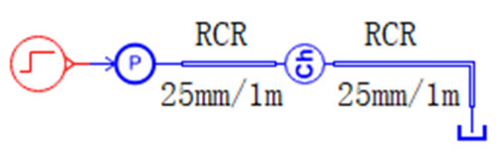
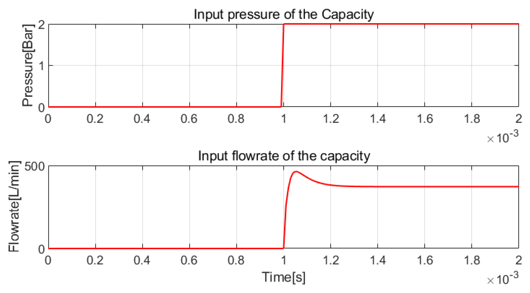
In the model presented in
Figure 7, a step pressure source is used to supply a line where there is only a capacity and a tank. The pressure/flowrate of the tank is zero. AMESim submodel HL0002 R-C-R is used before and after the capacity to simulate the effect of the fluid compressibility and friction of conduit walls of the conduits. Before the capacity, the flowrate changes as the pressure varies. Theoretically, a step pressure input will result in a maximum flowrate pulse at the inlet of capacity. The result in
Figure 8 shows that the flowrate is up to 464 L/min at the moment when the input pressure rises from 0 bar to 2 bar, and finally stays at 373 L/min. According to the explanation in
Figure 4, a flowrate of 373 L/min through the auxiliary line is able to make the flowrate through the main control line zero in the conditions where the load flowrate is under 373 L/min, which is quite large in most cases. Thus, applying such a capacity in this novel method is feasible.
- (2)
A basic Schematic for Zero-flowrate Switching Controller
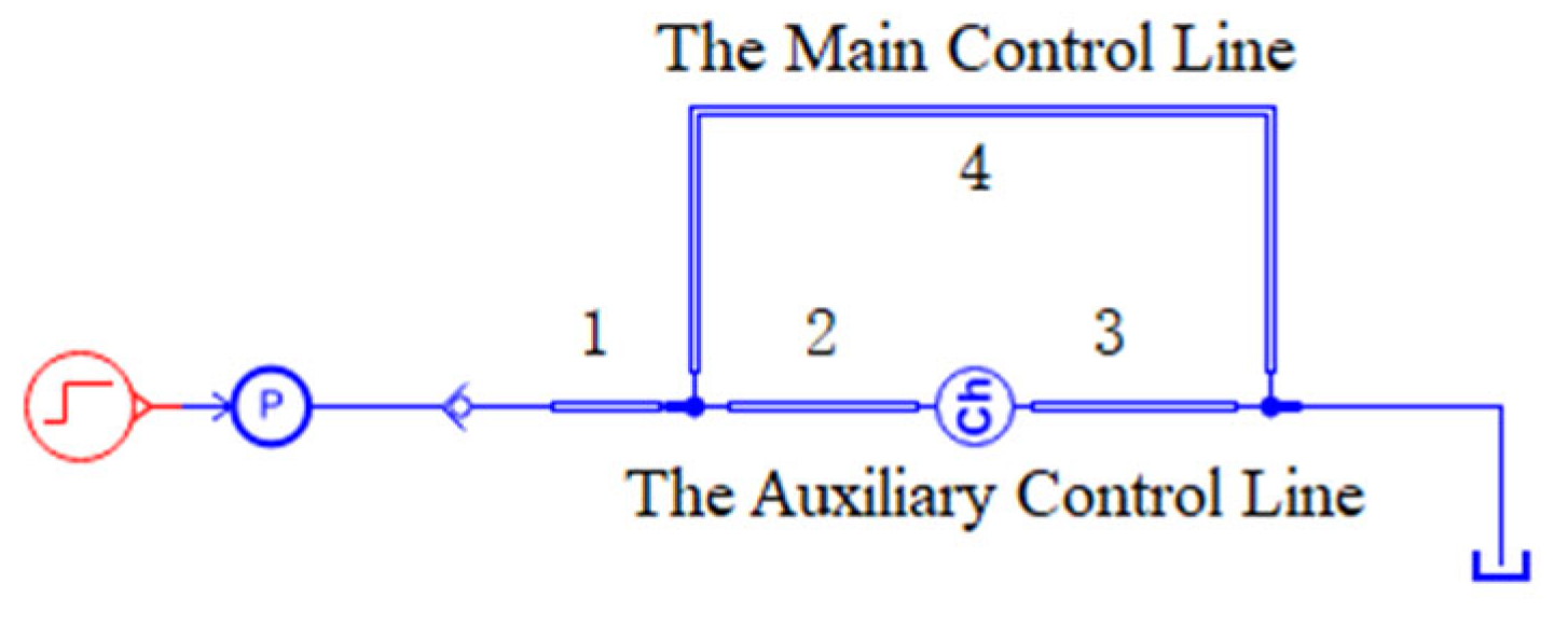
In the model presented in
Figure 9, a basic schematic for an improved zero-flowrate switching controller is simulated to validate the feasibility of the novel method. As
Figure 5 shows, there are two parallel lines, one of which is the main control line, and the other is the auxiliary control line. The main control line is the same one as shown in
Figure 7; the conduit through the line is modeled with AMESim submodel HL002 R-C-R. By adding a parallel auxiliary control line which consists of a capacity and two conduit models, it is possible to investigate the flowrate response and validate the feasibility of the novel method. To make flowrates of the two lines as required, the total resistance and capacitance through the two lines are considered with proper submodels and parameters: the capacity is 0.8 L; the submodels and parameters for conduit pieces 1, 2, 3, and 4 are presented in
Table 2.
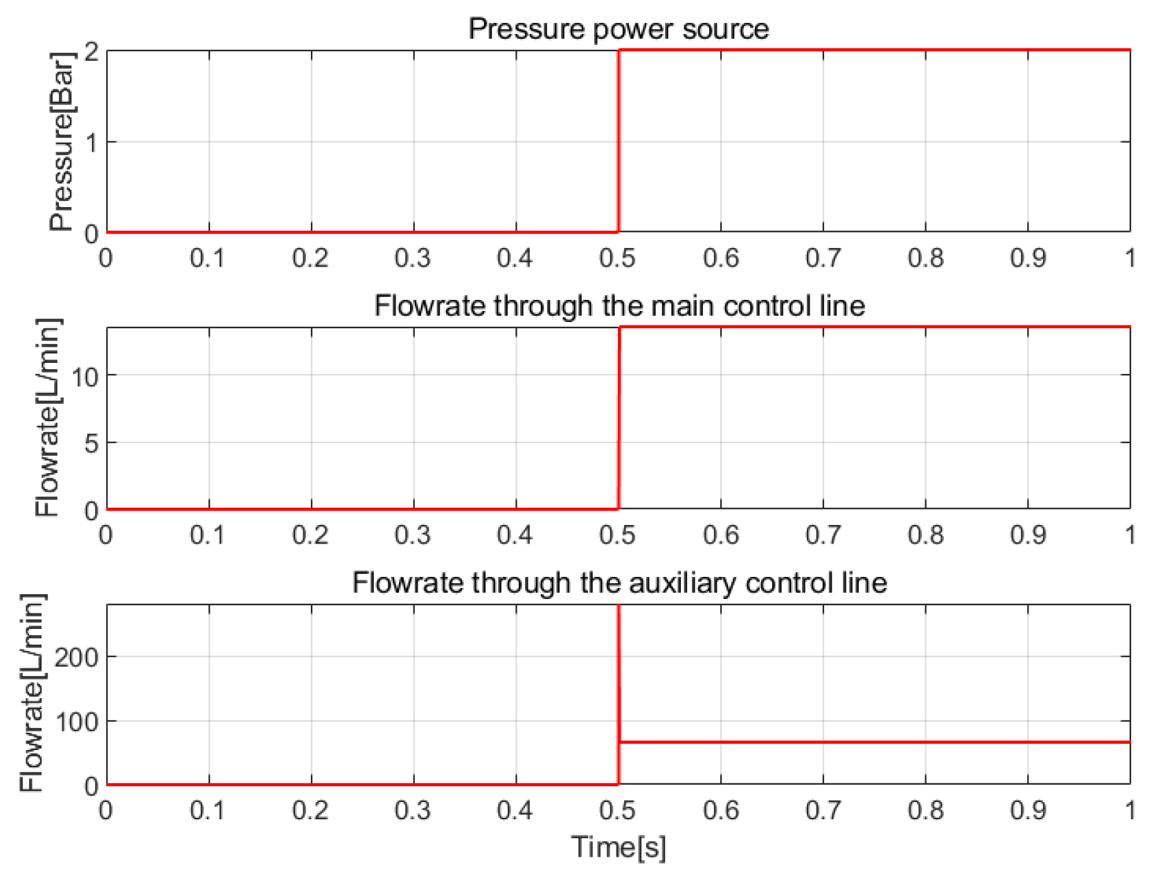
Figure 10 shows the simulation results for this model. The input pressure source is the same as that in the former model. The flowrates before capacity and through the main control line are presented in
Figure 10. When the input pressure increases, the flowrate through the main control line rises up to 13.6 L/min; the flowrate through the auxiliary control line first blows up to 281.3 L/min and then drops to 13.6 L/min, and finally stabilizes at this value.
5. Simulation Model of an Improved Zero-Flowrate Switching (IZFS) Controller
A simulation model (as presented in
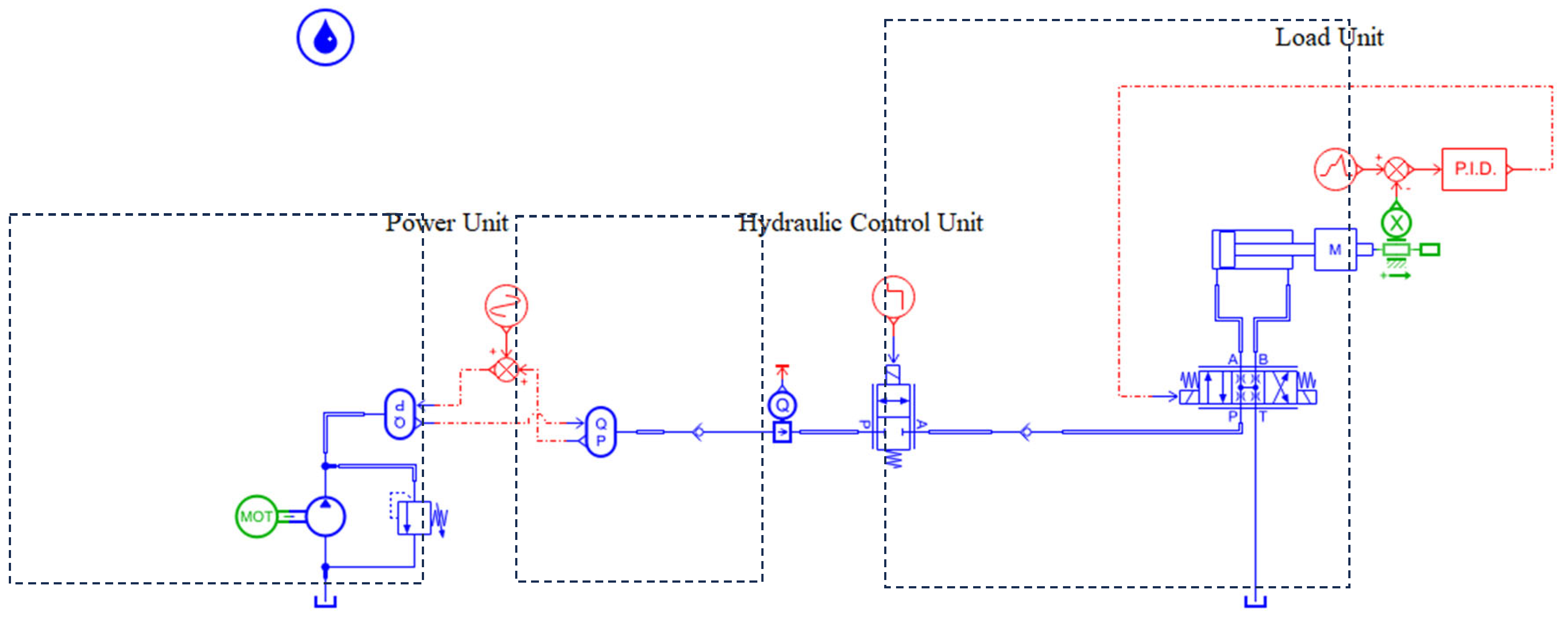
Figure 11) is now developed to validate the effectiveness of a zero-flowrate switching control method applied in a complete hydraulic actuation system. The power source is modelled with small pressure waves as a normal piston pump outputs for better accuracy; the load is a hydraulic cylinder moving at a constant speed; the hydraulic control unit is a zero-flowrate switching controller; check valve 1 is to prevent the flowrate from flowing from the capacity to the main control line; check valve 2 is to prevent the flowrate flowing from the load to the main control line and auxiliary line.
A contrast system is designed as
Figure 12 presents. The power unit and load unit are the same as those in a zero-flowrate switching control system, while there is only one switching valve applied in the hydraulic control unit. When there is a need to switch off the load system, the zero-flowrate switching control system will start a switching-off process as
Figure 6 explains, and the contrast system is to switch off the switching valve directly. The authors will analyze the performances and compare the efficiencies of the two systems to validate the feasibility of the improved zero-flowrate switching control method proposed in this work. More details about the two systems will be explained as follows.
5.1. The Power Unit
The model of a power unit is to simulate a real power source considering some dynamic characteristics. A real power source normally outputs small pressure waves instead of ideal constant pressure. This is due to the periodicity movement of the pistons inside the pump. For example, there are nine pistons within a pump, and the rotation speed of the pump is 1000 r/s; thus, the piston frequency is 111 Hz, which is also the frequency of output flowrates and pressures. In this simulation, a capacity is applied to regulate flowrates between two branches. Since it is possible for a capacity to generate vibrations with pressure waves, a power unit with small pressure waves is modeled for better accuracy of the evaluation of the system performance. In the simulation model, hydraulic submodels like pump (PU001) and relief valve (RV010) are used to offer a constant pressure of 100 bar. An expanded algebra model is built to add a wave characteristic to the output pressure of the pump. The output pressure of the pump unit is a sine wave whose frequency, amplitude, and average pressure are 111 Hz, 1 bar, and 100 bar, respectively.
5.2. The Load Unit
To better simulate the physical application, a hydraulic cylinder is used to generate a constant flowrate of 8 L/min; a closed-loop electronic controller is applied to keep the cylinder moving at a constant speed.
5.3. The Conduits
As shown in
Figure 8, a pressure drop of 2 bar is able to excite a flowrate increase of 373 L/min. Actually, it is not necessary to obtain such a large flowrate change in most applications. In this simulation model, conduits with proper diameters and lengths are used in both the main control line and auxiliary control line to regulate flowrates for the two branches. Conduits 1–5 are applied to offer capacity, resistance, and inductance for the two branches. Conduit 1 is before valve 1, and submodel HL0000 C is used here to simulate the capacity at the inlet of valve 1; conduit 2 connects valve 1 and the load, and submodel HL0001 C-R is used to simulate the capacitance and resistance of the conduit; conduit 3 connects check valve 1 and valve 2, and submodel HL0000 C is used to simulate the effect of capacitance at the inlet of valve 2; conduit 4 is actually the inlet of capacity; here, submodel HL0040 C-IR***C-IR is used to simulate the inertia, capacitance, and resistance of the inlet; conduit 5 is an inductance pipe after the capacity to stabilize flowrate and pressure, where submodel HL0040 C-IR***C-IR is used to simulate the inductance as well as the resistance and capacitance of the pipe. The parameters of the five pieces of conduits are presented in
Table 3.
5.4. The Model of an Improved Zero-Flowrate Switching (IZFS) Actuator
In the simulation model, an improved zero-flowrate switching control method, explained in
Figure 6, is applied to switch off the control line at minimum cost. The following model is designed to realize such a control method: a switching valve is used to control the main control line; a parallel auxiliary line is designed with a capacity volume in series for flowrate regulation. The capacity volume is a chamber with separate inlet/outlet ports instead of an accumulator whose inlet and outlet ports share the same port. When there are various pressures at the inlet and a constant pressure at outlet, there can be various flowrates at the inlet and stabilization of the flowrate at the outlet. Two switching valves are connected before/after the capacity to connect/disconnect the capacity with the system. In stage 4 of the switching process, the pressure of the capacity might be higher than that of power source; thus, check valve 1 is applied to prevent the flowrate from the capacity back to the pump or the main control line. During the switching-off process, there might be some oscillation in the cylinder, and check valve 2 will make flowrates at the end of the auxiliary control line more stable at zero, which makes the switching power loss of valve 3 absolutely zero.
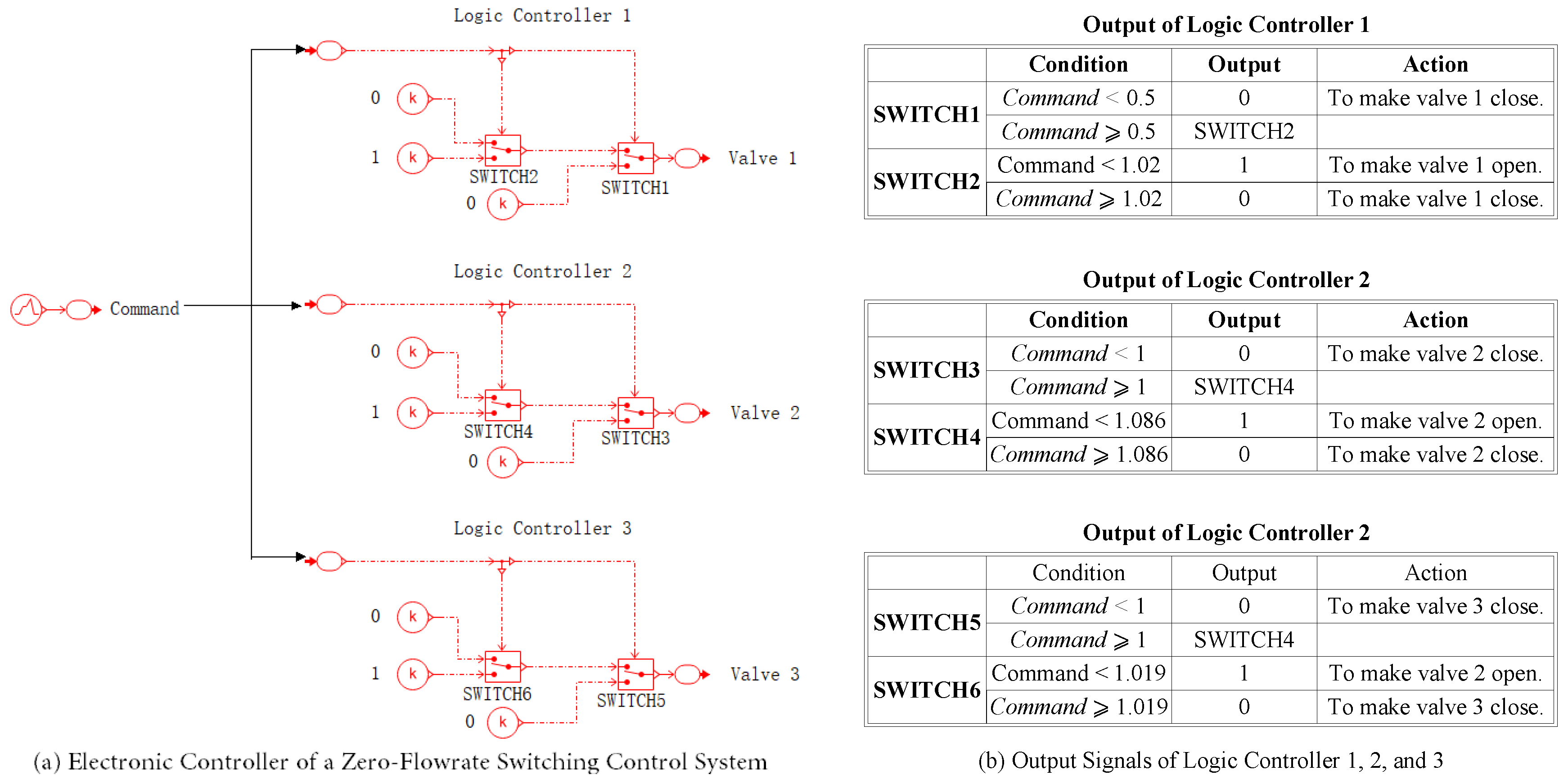
As explained in
Figure 13 and
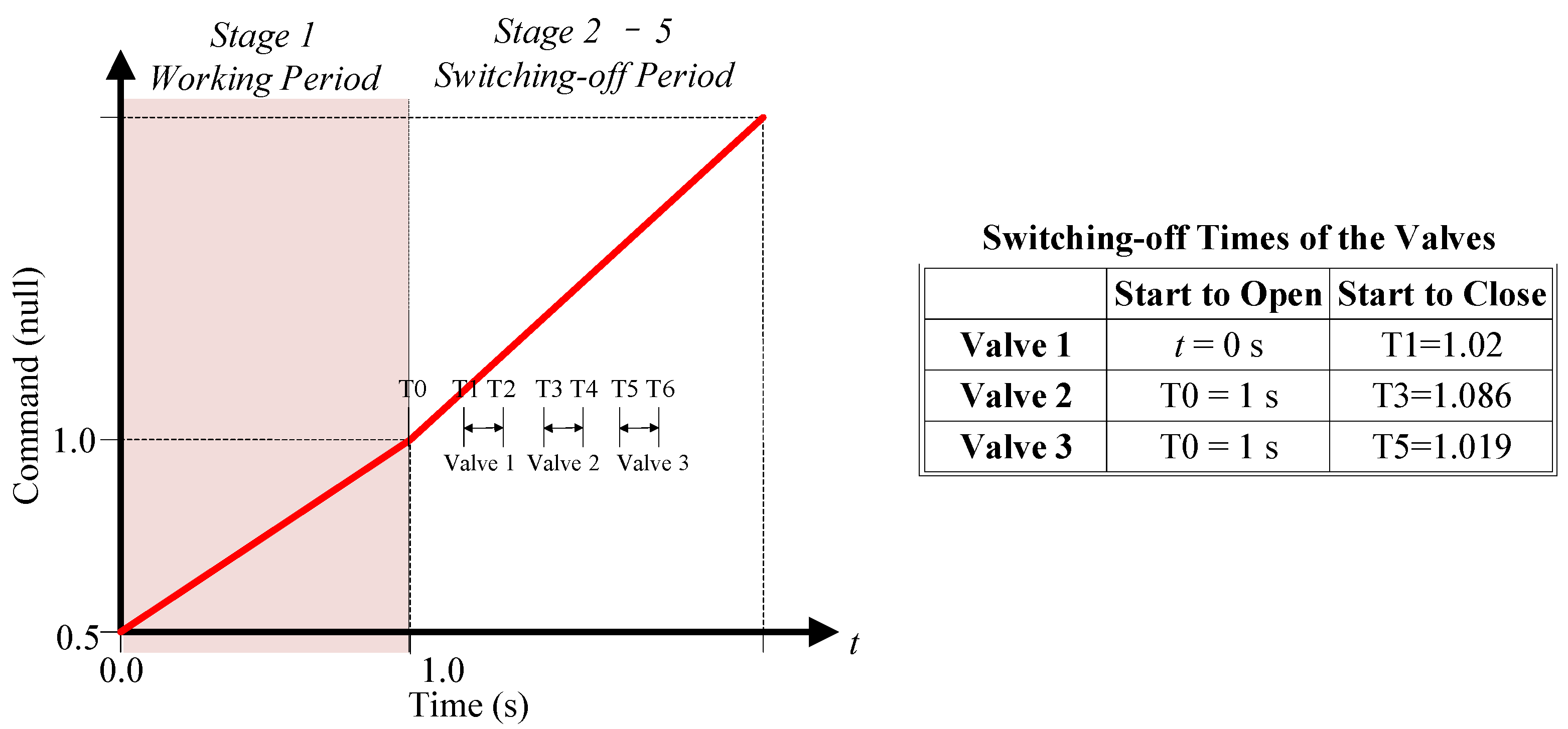
Figure 14, an electronic controller of a zero-flowrate switching control system is needed to send null signals to valves when the relating flowrate is zero. In the simulation model, the zero-flowrate times for valve 1, valve 2, and valve 3 are 1.02 s, 1.086 s, and 1.019 s, respectively; the closing time of the valves is 20 ms. As explained in
Figure 13, a linear piecewise signal is designed to control valves. When 0.5 ≤ command < 1, valve 1 is connected in the system and the load is working; when
Command = 1, the switching-off period starts: firstly, valve 2 and valve 3 switch on; then valve 1, 2, and 3 switch off at T1, T2, and T3 when flowrates are zero, respectively. When all the valves have switched off, the switching-off period is over.
Logic controllers 1, 2, and 3 are designed to convert the command to proper control signals for valve 1, 2, and 3. Take Logic control 1 for example; two SWITCH01 AMESim submodels are used to send out different signals on different conditions. When command < 0.5, SWITCH1 outputs 0; when command ≥ 0.5, SWITCH1outputs signals from SWITCH2; when command < 1.02, SWITCH2 = 1; when command ≥ 1.02, SWITCH2 = 0. Logic controller 2 and 3 are designed with similar principles as explained in
Figure 14.
5.5. A Hard Switching (HS) System
A hard switching control system is designed as a contrast. As presented in
Figure 13, a step signal is used to send a null signal to the switching valve when it is time to switch off the control line. The power source and the load are the same as those in an improved zero-flowrate switching control actuator system.
6. Simulation Results
As explained above, simulations of the improved zero-flowrate switching system and hard switching system were conducted. Switching power losses of each valve have been calculated as the production of the pressure drop and flowrates of the valves. Total switching power losses are also accumulated. Simulation results are presented in
Figure 15,
Figure 16,
Figure 17,
Figure 18 and
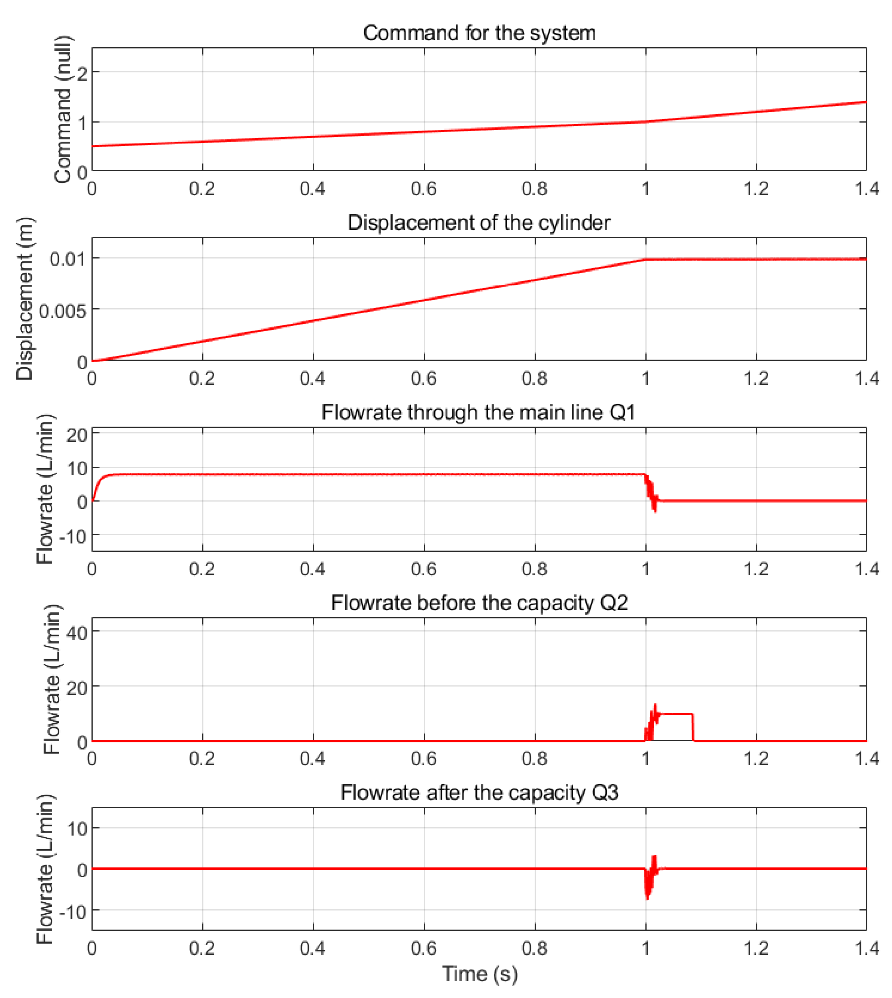
Figure 19. As presented in
Figure 16, when the electronic controller starts to send out a command at 0 s, the displacement of the cylinder starts to increase from 0 m linearly until the command signal becomes 1 at 1 s; then the cylinder piston stops at 0.01 m without any vibration, which validates that the displacement response of the zero-flowrate switching system is accurate and smooth. At 1 s, valve 2 and valve 3 switch on, the flowrate Q2 of valve 2 increases immediately, and the flowrate Q1 of valve 1 responds by dropping down; at the same time, the profile of flowrate Q3 through valve 3 sinks for a little bit due to the effect of capacity; after a little while, Q3 goes back to zero at 1.04 s. This is due to the effect of capacity. Before valve 2 and valve 3 switch on, the pressure of capacity is the tank pressure (0 bar); after the two valves switch on, the capacity starts to absorb fluid from both inlet/outlet ports until the outlet pressure achieves load pressure when flowrate Q3 is back to zero at 1.019 s, which is the time to switch off valve 3. When Q1 is equal to 0.8 L/min at 1.02 s, valve 1 starts to switch off; at the same time, Q2 through valve 2 keeps increasing until Q2 achieves 10 L/min, then Q2 stays at this value until t = 1.085 s, which is due to the effect of capacity. Then the capacity discharges fluid quickly and Q2 becomes zero at 1.086 s, when valve 2 starts to switch off.
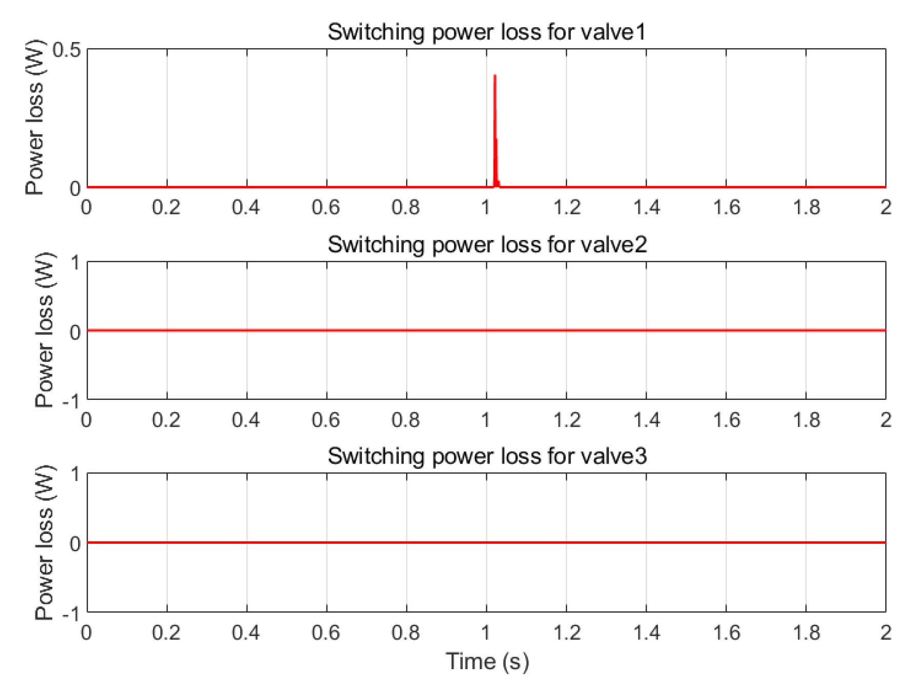
Figure 17 presents the switching power loss of valve 1, valve 2, and valve 3 in the IZFS system. After the switching-off command is sent out at 1 s, the switching power loss for valve 1 first peaks up to 0.4 W and then drops to 0 W quickly. The switching power losses for valve 2 and valve 3 are both 0 W.
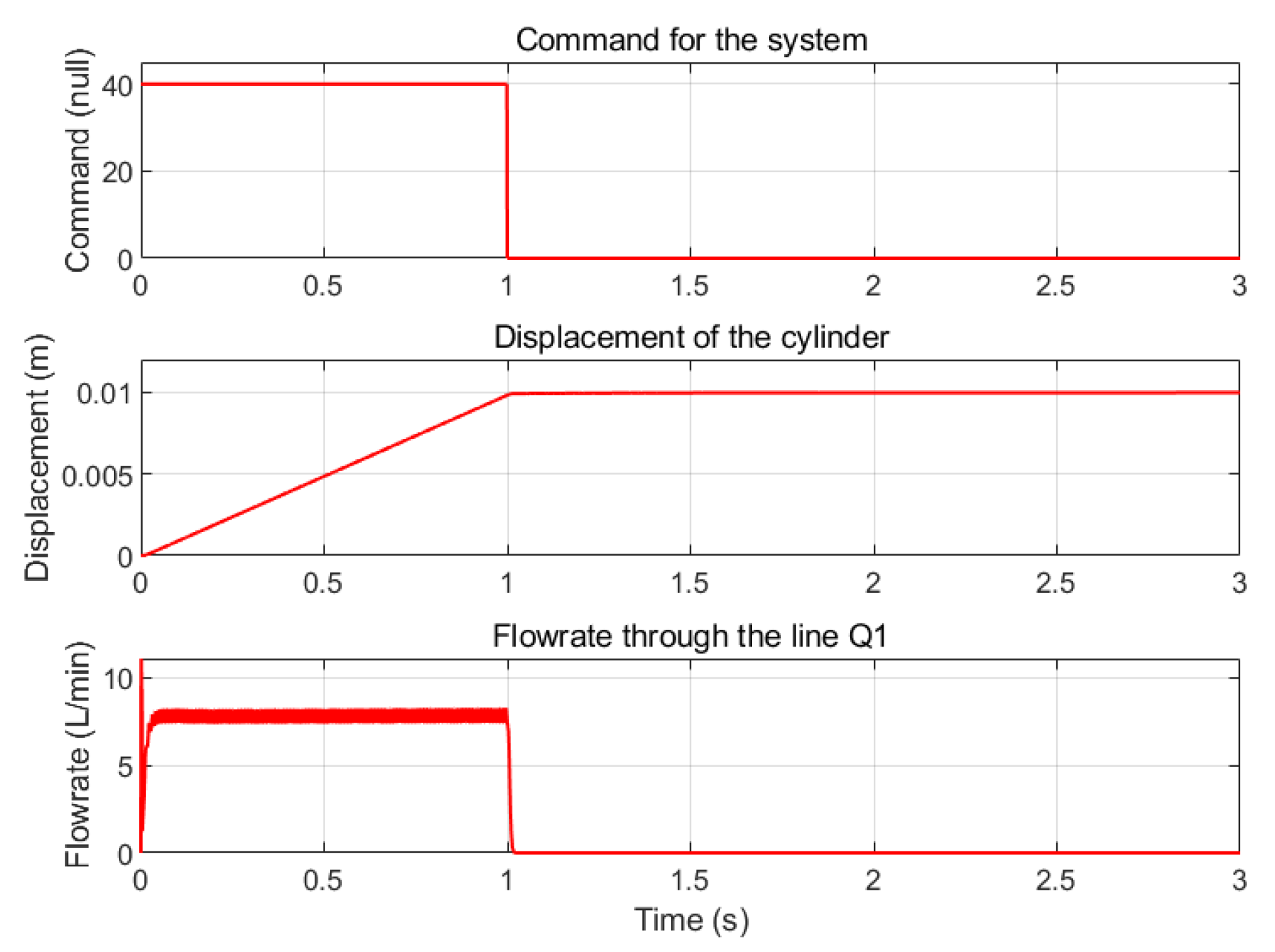
As a contrast, an HS system also shows a smooth and accurate displacement response as presented in
Figure 18. The average flowrate through the valve stays at 8 L/min.
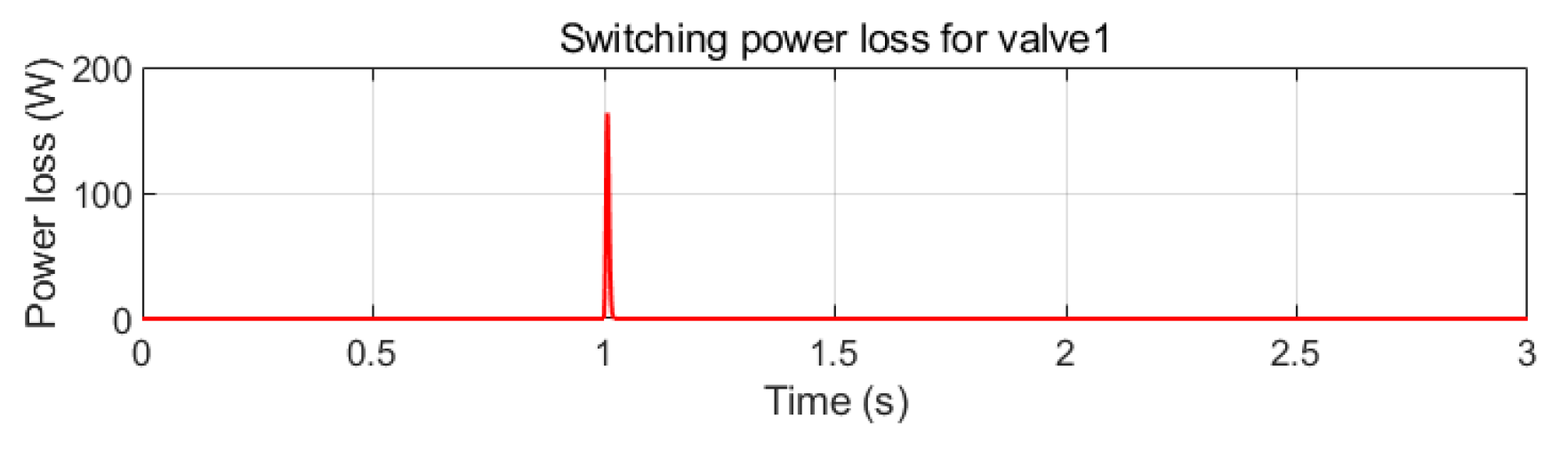
Figure 19 shows that the switching power loss of an HS system blows up to 163.62 W and then back to 0 W at 1.02 s, when the switching valve is totally switched off.
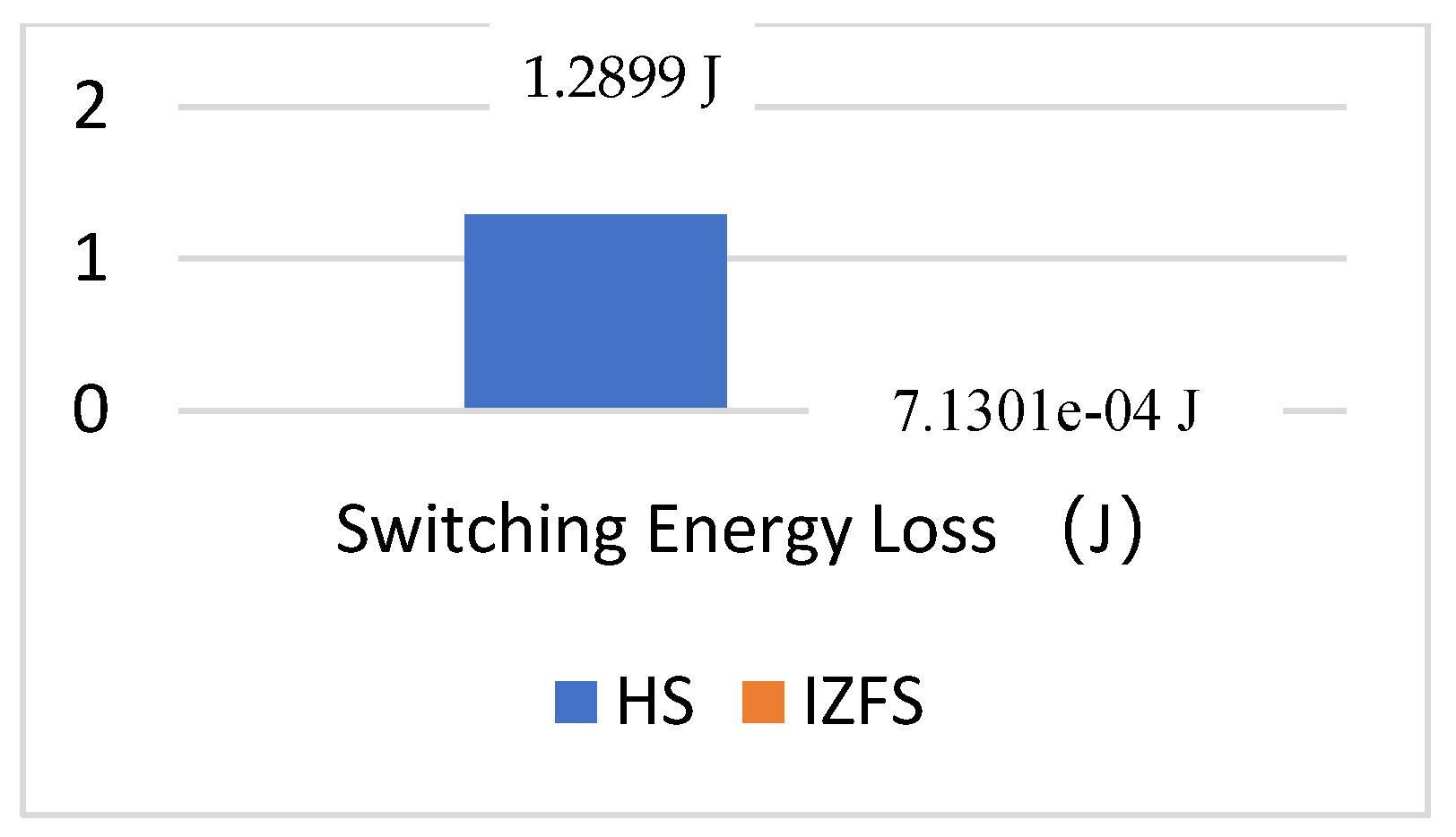
By comparing switching energy losses between IZFS and HS systems in
Figure 20, an IZFS system consumes 0.055% of the switching energy loss that is consumed by a HS system. In other words, an IZFS system makes the switching energy loss almost 0 J.
7. Discussion
With the characteristics of capacity investigated, the optimized design of resistance, inductance, and capacitance can be obtained, and can guide the optimized design of a complete zero-flowrate switching actuator. Generally, it can be seen that capacitance through the auxiliary line absorbs the flowrate that is supposed to flow through the main control line; thus, the capacitance should match the actual flowrates of the main control line. The inductance after the capacity works to stabilize the flowrate at the end of the capacity at zero for long enough until after the valve after closes totally. Furthermore, the resistance through the two control lines helps to regulate the flowrates through each line. By changing the ratio of resistances of the two lines, the ratio of flowrates through the two lines can be changed. The following can be concluded:
- (a)
A capacity is able to generate flowrate pulses. When there is a proper capacity in the line, it is able to generate a flowrate pulse which is up to 373.041 L/min when the pressure pulse is 2 bar.
- (b)
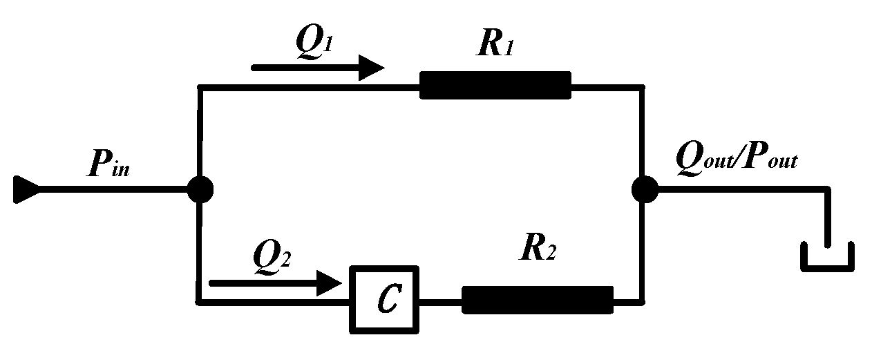
Flowrates for the main control line and auxiliary line can be regulated as desired by designing proper resistance and capacitance in each line. None of the hydraulic components is a pure capacitance or resistance. A capacity chamber is mostly a capacitive element while there is resistance at inlet/outlet ports; a piece of conduit is a typical resistive element while it also shows capacitive effect due to the elastic wall and compressibility of the fluid. To explain the effect of these capacitances and resistances in the system, lumped models presented in
Figure 20 are used to simulate different hydraulic components. The resistance through the main control line is regarded as a resistive element
R1; the resistance through the auxiliary line is regarded as a resistive element
R2; the total capacitance (capacitance of the capacity chamber and conduits) through the main control line is regarded as a capacitive element
C. With pressure pulse and capacitance
C, it is able to generate large flowrate pulses in the auxiliary line; with proper values of resistance
R1 and
R2, proper values of
Q1 and
Q2 can be obtained.
- (c)
In this work, the author chose to switch off valve 1 at 1.02 s when flowrate Q1 is 0.8 L/min. The total switching energy loss is 7.1301 × 10⁻⁴ J, which is almost 0 J. It is possible to switch off valve 1 when Q1 is absolutely 0 L/min at 1.031 s; as a result, the switching-off time is delayed by 11 ms. Therefore, it is a trade-off between a smaller flowrate and longer switching-off time. In a real application, the decision can be made depending on the actual requirements of the application.
8. Conclusions
This paper presents the basic principle and performance of an improved zero-flowrate switching method which is supposed to make the switching energy loss almost zero. Models with a capacity applied in a simple line are built to validate the feasibility of a capacity with two independent inlet/outlet ports proposed in this novel method; based on the validation, a complete zero-flowrate switching controller applied in a constant-speed actuator is modeled with hydraulic inductance, resistance, and capacitance described as lumped models. With optimization of capacitance, inductance, and resistance, simulation results shows that this novel control method is feasible to save switching energy by 99.945% as expected.
Author Contributions
Conceptualization, S.P.; Methodology, S.P.; Formal analysis, F.Y.; Investigation, S.P.; Resources, Y.H.; Data curation, S.P.; Writing—original draft, S.P.; Writing—review & editing, Y.H.; Visualization, S.P. All authors have read and agreed to the published version of the manuscript.
Funding
This research received no external funding.
Data Availability Statement
Data are contained within the article.
Conflicts of Interest
The authors declare no conflict of interest.
References
- Linjama, M. Digital fluid power–state of the art. In Proceedings of the Twelfth Scandinavian International Conference on Fluid Power, Tampere, Finland, 18–20 May 2011. [Google Scholar]
- Andruch, J.; Lumkes, J.H. Regenerative hydraulic topographies using high speed valves. In Proceedings of the SAE Commercial Vehicle Engineering Congress and Exhibition, Rosemont, IL, USA, 6–7 October 2009. [Google Scholar]
- Liu, S.; Yao, B. Coordinate control of energy saving programmable valves. IEEE Trans. Control Syst. Technol. 2008, 16, 34–45. [Google Scholar] [CrossRef]
- Xu, B.; Ding, R.; Zhang, J. Experiment research on individual metering systems of mobile machinery based on coordinate control of pump and valves. J. Zhejiang Univ. (Eng. Sci.) 2015, 49, 93–101. [Google Scholar]
- Gao, Q.; Zhu, Y.; Luo, Z.; Wang, R.; Song, Y.; Chen, X. Hardware-in-the-loop simulation for position control of hydraulic cylinder using high speed on/off valve. Trans. Beijing Inst. Technol. 2019, 39, 1091–1096. [Google Scholar]
- Jiao, Z.; Peng, C.; Wu, S. Progress in construction machinery multi-way valve and future trends. Chin. Hydraul. Pneum. 2013, 11, 1–6. [Google Scholar]
- Cao, J.; Gu, L.; Wang, F.; Qiu, M. Switch-mode hydraulic power supply theory. In Proceedings of the 2005 ASME-IMECE, Orlando, FL, USA, 5–11 November 2005. Paper No. IMECE2005-79019. [Google Scholar]
- Rannow, M.B.; Tu, H.C.; Li, P.Y.; Chase, T.R. Software enabled variable displacement pumps—Experimental studies. In Proceedings of the 2006 ASME-IMECE, Chicago, IL, USA, 5–10 November 2006. Paper No. IMECE2006-14973. [Google Scholar]
- Tu, P.Y.; Rannow, M.B.; Van de Ven, J.D.; Wang, M.; Li, P.Y.; Chase, T.R. High speed rotary pulse width modulated on/off valve. In Proceedings of the 2007 ASME-IMECE, Seattle, WA, USA, 11–15 November 2007. Paper No. IMECE2007-42559. [Google Scholar]
- Van de Ven, J.D. On fluid compressibility in switch-mode hydraulic circuits-Part I: Modeling and analysis. J. Dyn. Syst. Meas. Control 2013, 135, 021013. [Google Scholar] [CrossRef]
- Rannow, M.B.; Li, P.Y. Soft switching approach to reducing transition losses in an on/off hydraulic valve. J. Dyn. Syst. Meas. Control 2012, 134, 064501-1. [Google Scholar] [CrossRef]
- Peng, S. The concept of a zero-flowrate-switching controller. In Proceedings of the Eighth Workshop on Digital Fluid Power, Tampere, Finland, 24–25 May 2016. [Google Scholar]
- Peng, S. Modeling and theoretical analysis of zero-flowrate-switching control method for a dynamic load system to reduce switching power loss of control valves. Actuators 2023, 12, 183. [Google Scholar] [CrossRef]
- Hua, G.; Lee, F.C. Soft-switching techniques in PWM vonverters. IEEE Trans. Ind. Electron. 1995, 42, 595–603. [Google Scholar] [CrossRef]
Figure 1.
An actuation system with a switching valve.
Figure 1.
An actuation system with a switching valve.
Figure 2.
Pressure/Flowrate response in a zero-flowrate switching system.
Figure 2.
Pressure/Flowrate response in a zero-flowrate switching system.
Figure 3.
Switching power loss for a ZFS system.
Figure 3.
Switching power loss for a ZFS system.
Figure 4.
Principle of a ZFS system.
Figure 4.
Principle of a ZFS system.
Figure 5.
Schematic of an improved zero-flowrate switching controller.
Figure 5.
Schematic of an improved zero-flowrate switching controller.
Figure 6.
Sequence of operation of a zero-flowrate switching system.
Figure 6.
Sequence of operation of a zero-flowrate switching system.
Figure 7.
A system with a step pressure source and a capacity in the line.
Figure 7.
A system with a step pressure source and a capacity in the line.
Figure 8.
Pressure/Flowrate response of a system with a step pressure source and a capacity in the line.
Figure 8.
Pressure/Flowrate response of a system with a step pressure source and a capacity in the line.
Figure 9.
An improved zero-flowrate switching control line.
Figure 9.
An improved zero-flowrate switching control line.
Figure 10.
Simulation results for an improved zero-flowrate switching control line: step pressure power source; flowrate response through the main control line; flowrate response through the auxiliary control line.
Figure 10.
Simulation results for an improved zero-flowrate switching control line: step pressure power source; flowrate response through the main control line; flowrate response through the auxiliary control line.
Figure 11.
The simulation model of an improved zero-flowrate switching system in AMESim software.
Figure 11.
The simulation model of an improved zero-flowrate switching system in AMESim software.
Figure 12.
The simulation model of a hard switching system in AMESim software.
Figure 12.
The simulation model of a hard switching system in AMESim software.
Figure 13.
Command signals of the electronic controller.
Figure 13.
Command signals of the electronic controller.
Figure 14.
Description of logic controller 1, 2, and 3.
Figure 14.
Description of logic controller 1, 2, and 3.
Figure 15.
Displacement/Flowrate performance of IZFS system.
Figure 15.
Displacement/Flowrate performance of IZFS system.
Figure 16.
Switching power loss of IZFS system.
Figure 16.
Switching power loss of IZFS system.
Figure 17.
Displacement/Flowrate performance of HS system.
Figure 17.
Displacement/Flowrate performance of HS system.
Figure 18.
Switching power loss of HS system.
Figure 18.
Switching power loss of HS system.
Figure 19.
Comparison of switching energy losses between IZFS/HS systems.
Figure 19.
Comparison of switching energy losses between IZFS/HS systems.
Figure 20.
Hydraulic schematic with lumped resistance and capacitance.
Figure 20.
Hydraulic schematic with lumped resistance and capacitance.
Table 1.
Working states of three valves in five stages.
Table 1.
Working states of three valves in five stages.
| | Valve 1 | Valve 2 | Valve 3 |
|---|
| Stage 1 | ON | OFF | OFF |
| Stage 2 | ON | ON | ON |
| Stage 3 | OFF | ON | ON |
| Stage 4 | OFF | ON | OFF |
| Stage 5 | OFF | OFF | OFF |
Table 2.
Submodels and parameters of conduits in the main control line/auxiliary control line from load to the control unit.
Table 2.
Submodels and parameters of conduits in the main control line/auxiliary control line from load to the control unit.
| CONDUIT PIECE | SUBMODEL | DIAMETER (mm) | LENGTH (m) |
|---|
| 1 | HL002, R-C-R | 25 | 0.01 |
| 2 | HL002, R-C-R | 25 | 1 |
| 3 | HL002, R-C-R | 8 | 0.2 |
| 4 | HL002, R-C-R | 10 | 1 |
Table 3.
Parameters of the conduits.
Table 3.
Parameters of the conduits.
| Conduit | Submodel | Diameter (mm) | Length (m) |
|---|
| ① | HL0000 C | 25 | 0.01 |
| ② | HL0001 C-R | 4 | 0.1 |
| ③ | HL000 C | 25 | 0.01 |
| ④ | HL0040 C-IR***C-IR | 25 | 0.01 |
| ⑤ | HL0040C-IR***C-IR | 8 | 0.2 |
| Disclaimer/Publisher’s Note: The statements, opinions and data contained in all publications are solely those of the individual author(s) and contributor(s) and not of MDPI and/or the editor(s). MDPI and/or the editor(s) disclaim responsibility for any injury to people or property resulting from any ideas, methods, instructions or products referred to in the content. |
© 2024 by the authors. Licensee MDPI, Basel, Switzerland. This article is an open access article distributed under the terms and conditions of the Creative Commons Attribution (CC BY) license (https://creativecommons.org/licenses/by/4.0/).


