Abstract
A high-precision ground microgravity simulation environment serves as the prerequisite and key to studying landing dynamics in microgravity environments. However, the microgravity level accuracy in traditional ground simulation tests is difficult to guarantee and fails to precisely depict the collision behavior of massive spacecraft. To solve such problems, this paper takes the microgravity simulation system based on quasi-zero stiffness (QZS) mechanism as the research object, and simulates a high-precision and high-level microgravity environment. Then, the collision contact force model of the planar foot and high elastic body rubber is established, the landing dynamics research under different microgravity environments is carried out, the influence of different microgravity environments on the landing behavior of large mass spacecraft is analyzed in depth, and ground microgravity simulation experiments are carried out. The results show that the microgravity simulation level reaches 10−4 g, the error of gravity compensation for each working condition is not more than 4.22%, and the error of sinking amount is not more than 4.61%, which verifies the superior compensation performance of the QZS mechanism and the accuracy of the dynamic model.
1. Introduction
In recent years, mankind has made great progress in the field of deep space exploration. Asteroid exploration is undoubtedly a hot issue that has attracted much attention; asteroid exploration is of great significance for the exploration of the origin of life, the exploitation of space resources, and the prediction of the safety of the Earth [1,2,3]. A total of 14 small body surveys have been conducted by various countries, and several asteroid surveys are planned [4]. The weak gravitational pull of asteroids and the complexity of the landing environment make it difficult to describe the dynamical behavior. Under such conditions, the lander is very prone to jumping away from the phenomenon [5,6], making it difficult to realize high-precision landing. Therefore, it is necessary to use experimental means to study the collision dynamics in a microgravity environment.
The prototype of the continuous contact force model is the Hertz theory model [7], which can express the contact force as a nonlinear function of the deformation amount. The essence of the collision process is the mutual transformation and dissipation of energy between colliding bodies, and Hertz theory does not describe the energy dissipation phenomenon in the collision process, which hinders the further application of Hertz theory in the collision dynamics of multibody systems [8,9,10]. To introduce an artificial damping factor, Kelvin and Voigt [11] in 1960 used a linear spring damping model to calculate the energy dissipation during the contact process. This model leads to discontinuities in the contact forces and the existence of negative collision forces, which violates the physical meaning of mechanics and fails to completely describe the phenomenon of energy dissipation during collisions. To avoid this phenomenon, the literature [11] describes the damping coefficient as a function between the damping factor and the amount of contact deformation. The development of the contact force model has evolved into the study of damping factors by many scholars, among which the widely accepted Hunt–Crossley model [12] proposes a contact force model that assumes that the coefficient of restitution is a linear function of the initial collision velocity in order to derive the damping factor. Meanwhile, other models, such as the Hu–Guo model [13], the Shen model [14], and the Zhang model [15,16], have used different assumptions or approximate calculation methods to obtain different damping expressions. The initial collision velocity is included in the denominator of the damping term in the above models, which leads to numerical singularity problems during numerical simulations of particulate matter [17,18]. This paper is based on the regularization method [19], which considers that each contact region of the contact body is covered with some spring-damping elements, avoiding the fact that the initial collision velocity is included in the denominator of the damping term [20]. In this paper, the contact foot is a planar foot and the simulated landing surface is a highly elastic body sponge, and the collision behavior of this system can be equated to a single-degree-of-freedom linear spring-damped system by the regularization method [19].
The methods of microgravity simulation include the tower drop method [21], water floating method [22], air floating method [23], suspension method, and slope simulation method. Although the tower drop method and air flotation method have high levels of microgravity simulation, they have limitations on degrees of freedom and are not suitable for studying collision dynamics. At present, the commonly used methods for conducting landing dynamics research include the suspension method and the slope simulation method. The ground verification test of Philae [24] used the active tensioning rope of the robotic arm to land Philae on landing surfaces of different degrees of hardness and hardness in microgravity environment. However, this suspended method has high requirements for the control system, and the disturbance of the ropes can have a significant impact on the experiment. The SpaceBok invented by the Kolvenbach team [25] can achieve jump detection on the landing surface, and the ground validation test uses an air floating inclined platform. There is also a way to simulate a microgravity environment based on the quasi-zero stiffness mechanism. Niu et al. [26] achieved simulation of a microgravity environment through a mechanical quasi-zero stiffness mechanism with series tension, but the disturbance of ropes and frictional resistance can cause significant errors in the experimental results.
To avoid the problem of mechanical friction, Zhou and Hou et al. [27,28] realized the simulation of a microgravity environment by magnetic quasi-zero stiffness (QZS) mechanism, and verified the superiority of the QZS mechanism’s compensation ability by test. Based on that, this paper optimizes the loading capacity of the microgravity simulation device by means of a nitrogen balancer, so that the system can withstand a load of 620 kg. A collision contact force model for a foot-superelastic body is developed. We study the collision behavior of a massive spacecraft during landing in a microgravity environment. The effects of different microgravity environments on the collision behavior are analyzed through theoretical and experimental studies. It provides a theoretical basis for the realization of landing exploration of massive spacecraft in a microgravity environment. At the same time, combining the NES-AVS damping method proposed by Xu et al. [29] provides direction for the design of the buffer structure of the detector. The main structure of this article is as follows. Section 2 presents a collision model of the foot-superelastic body in the form of a single-degree-of-freedom linear spring damping system. A relationship for the collision contact force is also derived. Section 3 validates and analyzes the dynamic model and discusses the collision characteristics of spacecraft under different gravitational accelerations. Section 4 verifies the accuracy of the model again through ground equivalent tests, and provides suggestions for the microgravity simulation device by comparing the theoretical model with the experimental results.
2. Dynamic Modeling of Collision Contact Forces
To carry out the research on the collision dynamics of heavy spacecraft in a microgravity environment, this paper realizes the microgravity environment by means of the QZS mechanism and a Pascal nitrogen balancer. The servo system is stroke amplified to carry out the ground landing test in microgravity environment and to analyze the motion state of spacecraft in different microgravity environments and provide theoretical basis for optimizing the microgravity simulation device.
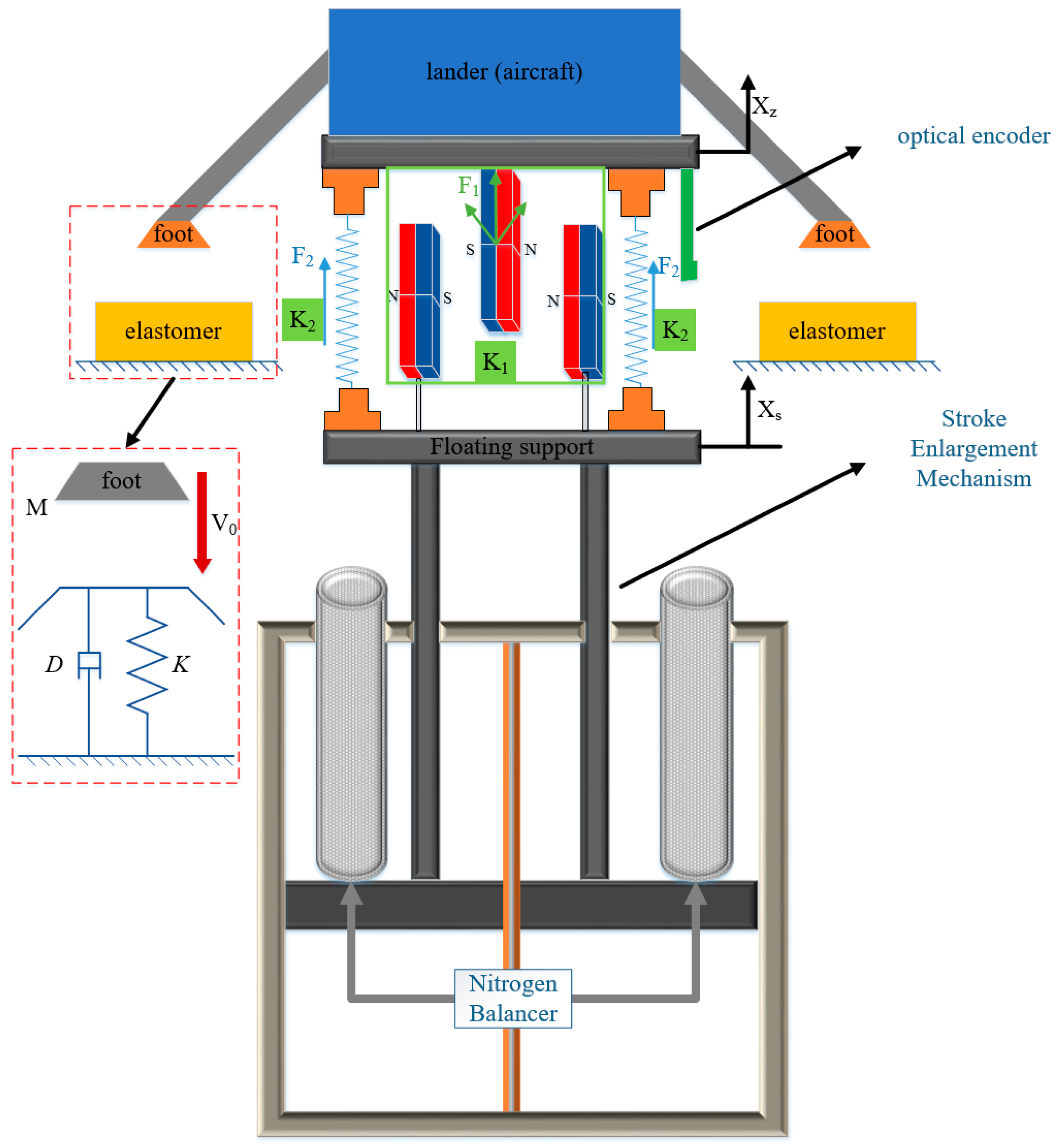
The collision contact force model is an important indicator of whether a massive spacecraft can be successfully probed in a microgravity environment. In this paper, the landing foot is a cylinder and the landing surface is a highly elastic rubber model. The collision model of the foot-superelastic body can be equivalent to a linear spring damping system, and the damping coefficient can be derived from the vibration system. The schematic diagram of the microgravity simulation system is shown in Figure 1 below.

Figure 1.
Sketch of the microgravity simulation device.
For the single-degree-of-freedom linear vibration equation, the dynamics can be described by Equation (1).
where K is the contact stiffness of the high carbon body rubber, not the Hertz contact stiffness, D is the damping coefficient of the high elastomer rubber, and δ is the displacement of the landing foot embedded in the rubber, which is referred to as deformation in this article. The analytical solution of the above dynamical equations can be expressed by Equation (2).
where A is the amplitude of the system, is the phase angle, is the frequency of vibration, ; is the intrinsic frequency , and is the damping ratio of the vibrating system .
The collision model can also be expressed in Equation (3).
where , . The initial conditions of the system are . The amount of deformation during collision can be expressed as Equation (4), and the relative deformation velocity can be expressed as Equation (5).
As long as the compressive force is always positive, the landing foot remains in contact with the projectile, and its dynamics can be expressed as Equation (6). The time at the end of contact can be expressed as Equation (7).
The relative deformation velocity at this moment can be expressed by Equation (8).
According to Newton’s definition of the coefficient of recovery, the relationship between the coefficient of recovery and the damping ratio can be expressed as Equation (9).
The damping ratio of the high-elastomer rubber is greater than 0 around 0.1 and H can be taken as 1. The collision contact time can also be represented by π/ωd, expressed as Equation (10).
By substituting Equation (10) into Equation (8), the relative deformation velocity at that moment can be expressed as Equation (11):
According to Equation (11), the recovery coefficient can be expressed as Equation (12).
Taking the logarithm on both sides of Equation (9), it can be expressed as Equation (13). Taking the logarithm on both sides of Equation (12), it can be expressed as Equation (14).
Combining Equations (13) and (14), the collision contact force model can be expressed as Equation (15).
The simplified result of the collision contact force model from Equation (8) can be expressed as Equation (16).
3. Dynamics Simulation of Microgravity Analog Systems
3.1. Simulation Modeling of Microgravity Simulation Systems
The research object of this paper is a spacecraft in the microgravity environment, to meet the demand of heavy-duty spacecraft. In this paper, the compensating force provided by the Pascal nitrogen balancer is added, the supporting force is still provided by the QZS mechanism, and the stiffness function of the QZS mechanism can be expressed by Equation (17). At the same time, it also represents the variation of the constant force output of the quasi-zero stiffness mechanism.
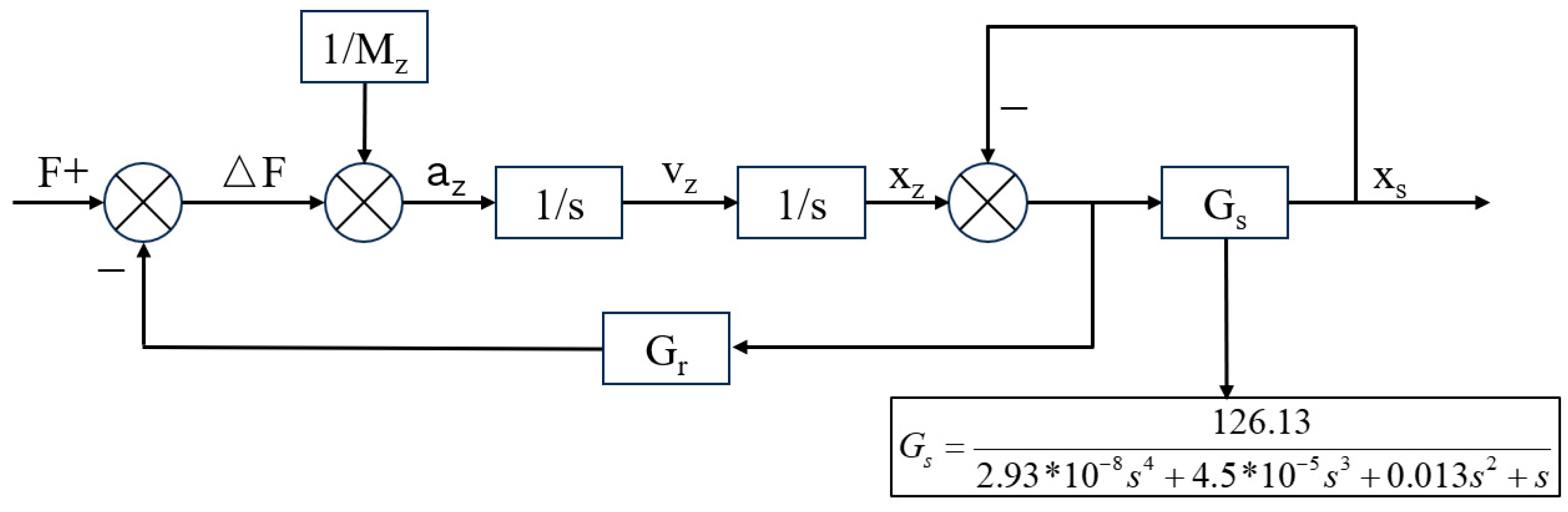
The control strategy of the servo system adopts PID control, since the QZS mechanism is connected in parallel with the stroke amplification mechanism and the dis-placement of the QZS mechanism is small during the movement; the relative displacement between the floating support and the lander is used as the control feedback. Gs is the transfer function of the stroke amplification mechanism. QZS mechanisms and cylinders provide support forces on the spacecraft to enable unloading in full gravity, so that the system is in equilibrium when there is no external excitation. This article adopts closed-loop control based on position information instead of traditional force closed-loop control strategy, which effectively avoids the impact of force sensor errors. Therefore, this article uses x as feedback to participate in the control loop of the stroke amplification mechanism. When x approaches 0, it can ensure a stable output of the constant force F, and the impact will be responded to by the QZS system first, reducing the system’s control requirements for the stroke amplification mechanism. The control flowchart is shown in Figure 2.

Figure 2.
Control flow chart.
The simulation parameters of the kinetic model are shown in Table 1 below.

Table 1.
Simulation parameters.
3.2. Simulation and Analysis of Crash Dynamics
The system is in equilibrium before the start of the test. To investigate the effect of different microgravity environments on the landing behavior of massive spacecraft, in this paper, the microgravity environment is divided into three working conditions and different loads are used to simulate the microgravity environment: external loads of 490 g, 1 kg, and 50 g + 1 kg, where 490 g is used to simulate a microgravity environment at 7.73 mm/s2 and 1 kg is used to simulate a low-gravity environment at 15.78 mm/s2. The 50 g + 1 kg condition is divided into two stages. In the first stage, an external excitation of 50 g is used to simulate a microgravity environment of 0.8 mm/s2. The second stage refers to an additional 1 kg of external excitation when the spacecraft is 25 mm from the landing surface. This phase is used to simulate the grip during landing. A dynamic simulation model is established through the above test conditions to study the simulation accuracy of the microgravity simulation device under different working conditions and the effect of the impact force on the rubber deformation at the moment of landing. The test conditions are shown in Table 2 below.
Table 2.
Simulation conditions.
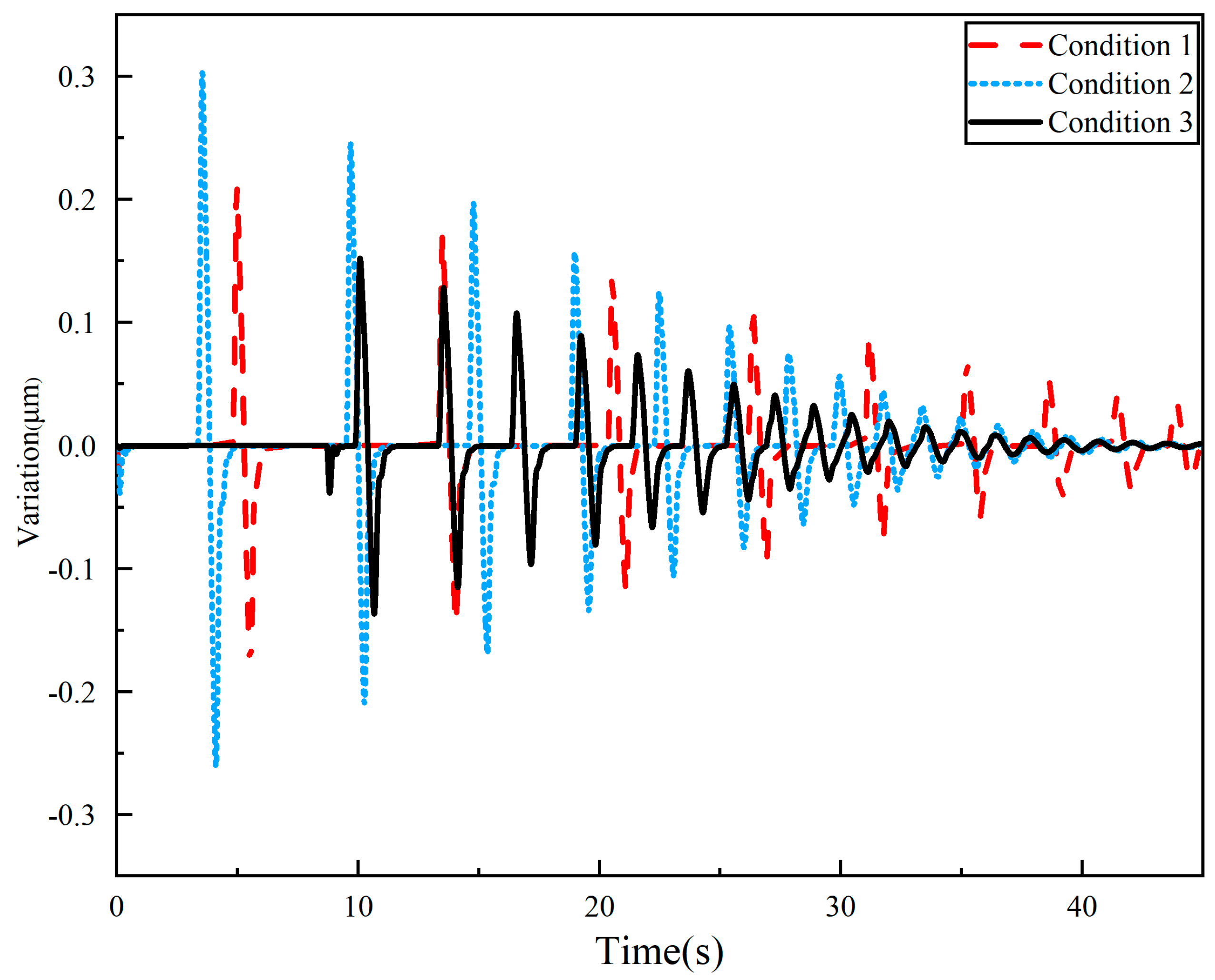
Before exploring the landing behavior, it is necessary to analyze and discuss the compensation ability of the microgravity simulation system. The displacement difference between the lander and the floating support can be defined as the variation of the flexible unit. The output constant force value of the whole system can be stabilized when the change amount of the flexible unit tends to 0. This proves that the QZS mechanism can still show superior compensation ability when carrying a large-mass spacecraft. The displacement difference (variation) curves of the flexible unit under different external excitations are shown in Figure 3 below.

Figure 3.
Displacement variation of QZS mechanism under three test conditions.
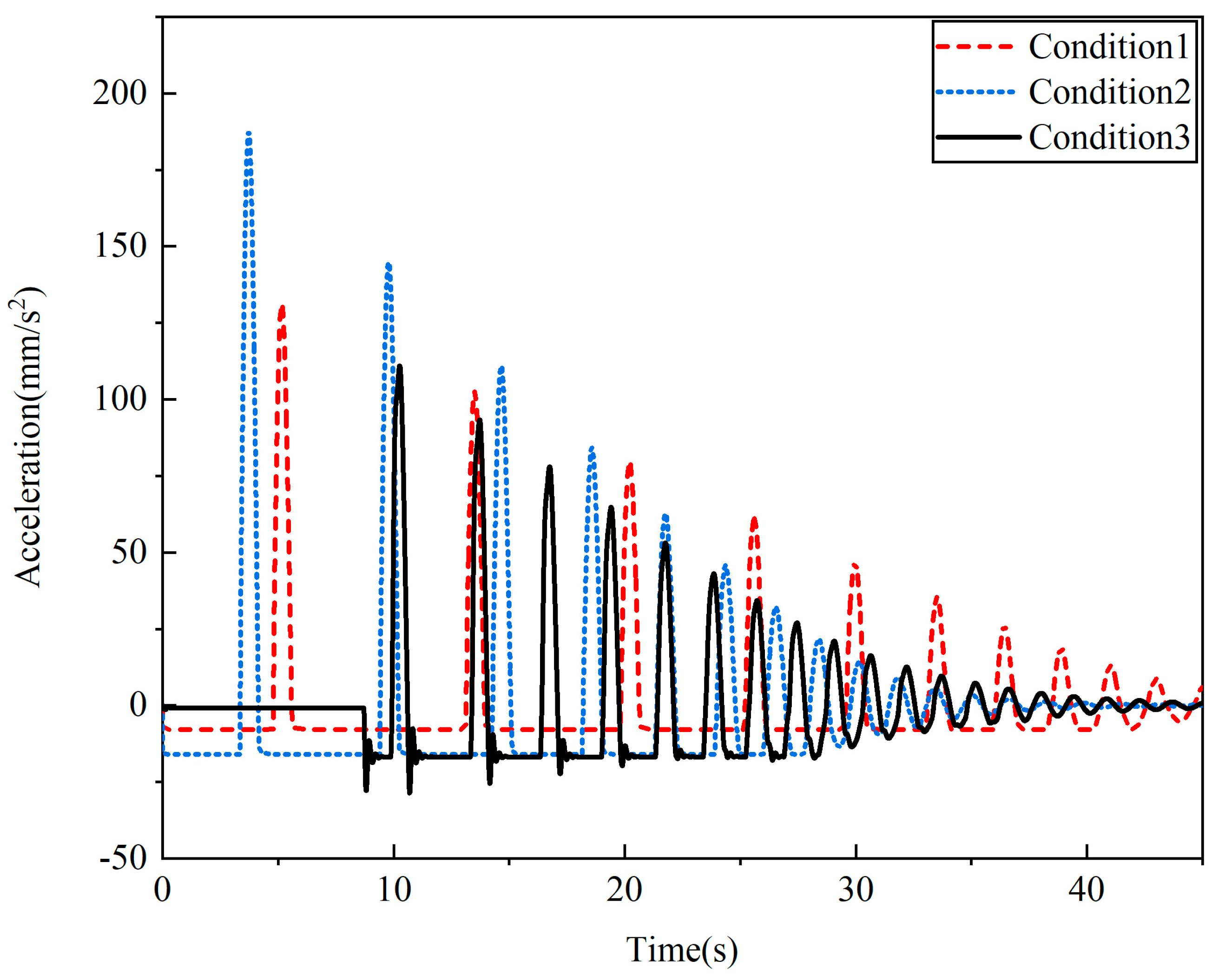
According to the simulation results, it can be seen that the relative displacement changes of the flexible units in conditions 1–3 are 0.2 μm, 0.3 μm, and 0.15 μm, respectively, at the instant of collision and landing. The stiffness of the QZS mechanism is 35.51 N mm, the change in constant force is negligible on the order of 10−3, and it proves that the QZS mechanism can play the role of buffer very well at the instant of collision, and ensure the stability of the support force output. In order to further verify the superior accuracy of the constant force compensation, the acceleration of the spacecraft needs to be analyzed and discussed, and its acceleration simulation curve is shown in Figure 4.
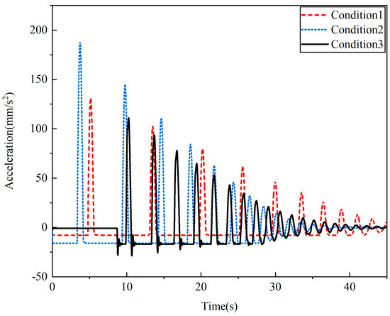
Figure 4.
Acceleration curve of the lander under three test conditions.
Comparing the acceleration simulation curves, when the landing boundary conditions are certain, the acceleration value can be kept stable during the free-fall process, and the gravitational error with the ideal microgravity environment is only 1.4%. The spacecraft acceleration increases instantaneously at the moment of contact collision, and the collision acceleration is positively correlated with the external excitation. The simulation results are shown in Table 3.
Table 3.
Simulation results.
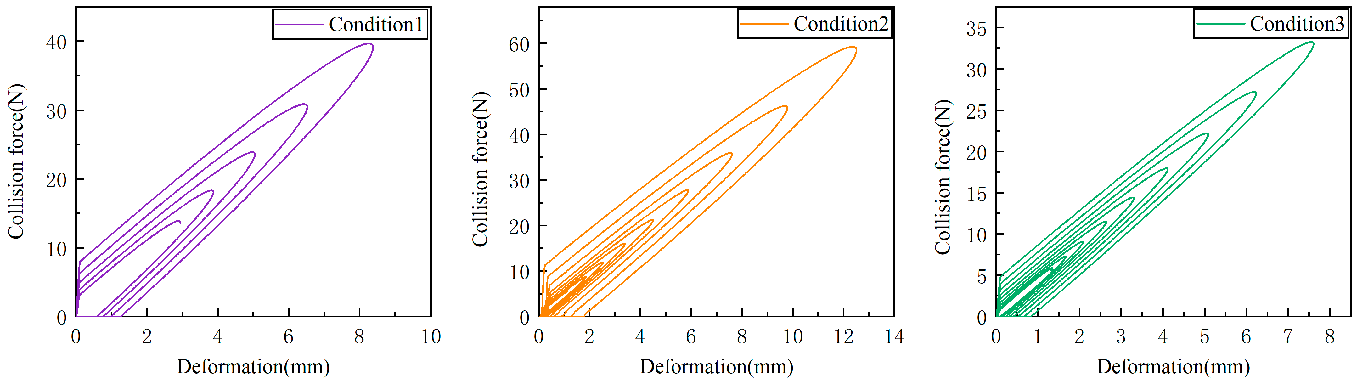
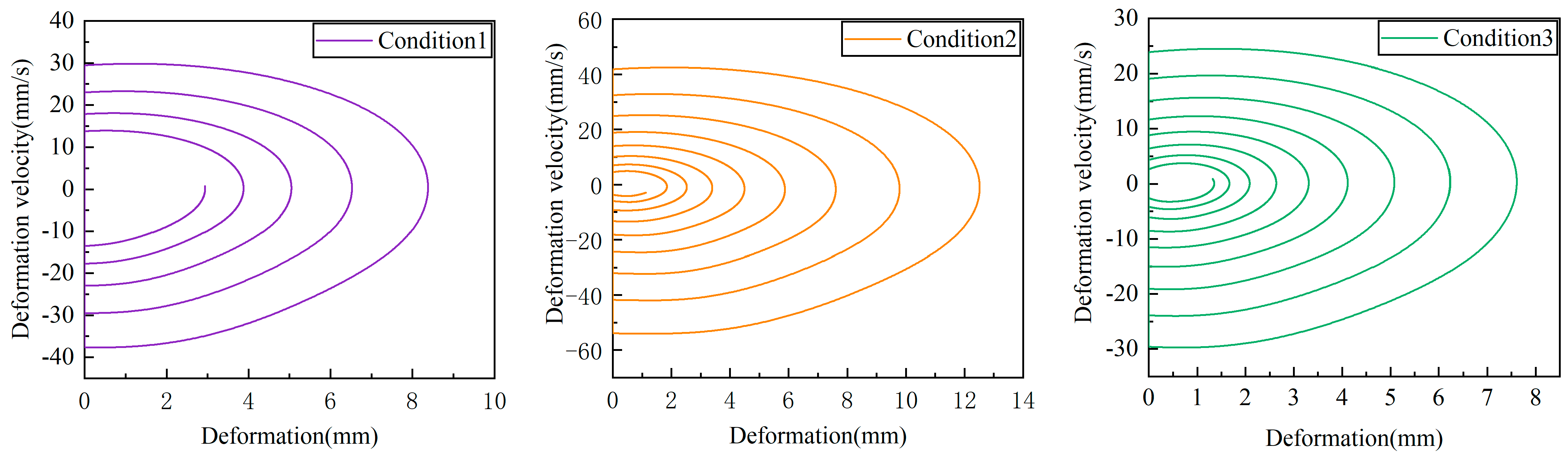
Acceleration simulation results show that the microgravity simulation level can reach 10−4 g, which can further study the landing behavior of spacecraft in microgravity environment. The simulation time of the microgravity environment is set to 30 s, and the relationship between the collision force and the amount of deformation under the three working conditions is shown in Figure 5. The relationship between deformation velocity and deformation is shown in Figure 6.
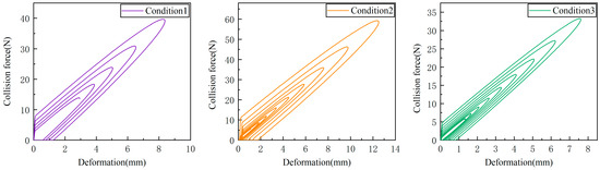
Figure 5.
Relationship between collision forces and deformation.
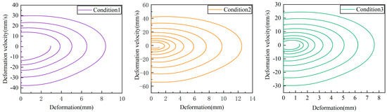
Figure 6.
Relationship between deformation velocity and deformation.
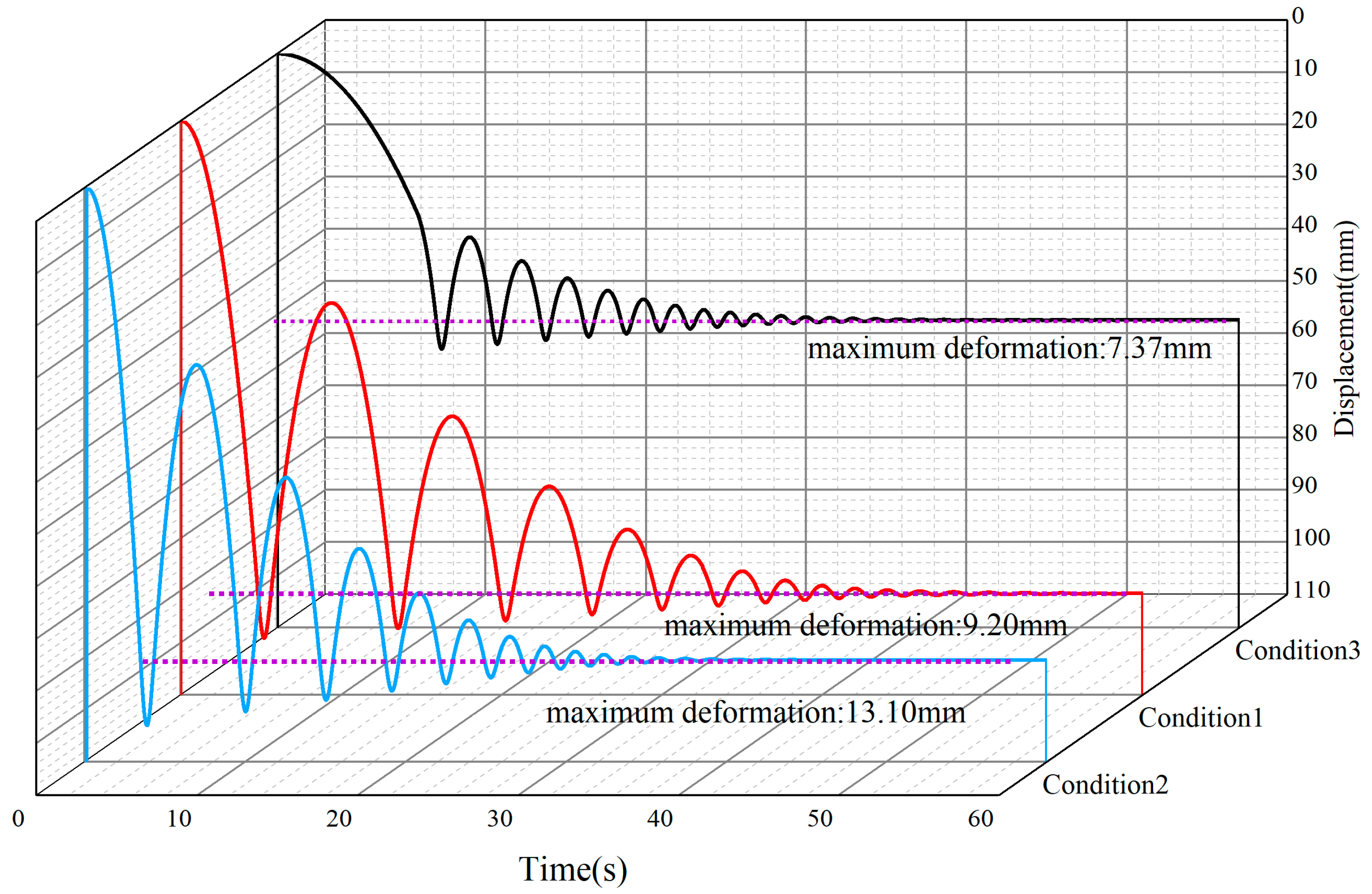
The displacement profile of the spacecraft in a microgravity environment is shown in Figure 7.
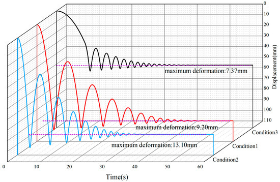
Figure 7.
Displacement curves of the lander under three test conditions.
4. Experimental Study of a Microgravity Simulation System
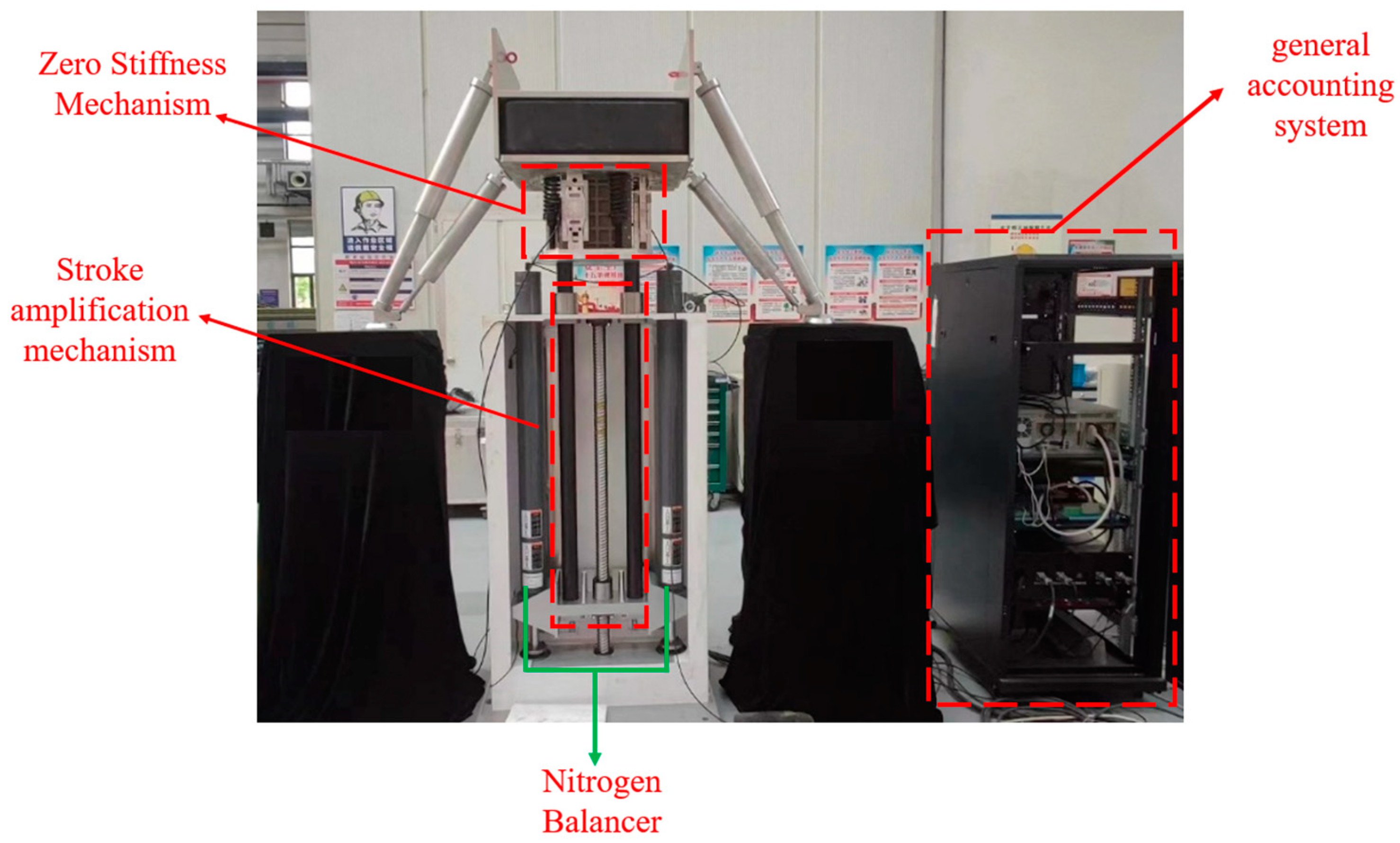
The microgravity simulation system test simulation is shown in Figure 8, which consists of four main components: the QZS mechanism, the stroke amplification mechanism, the general accounting system, and the nitrogen balancer.
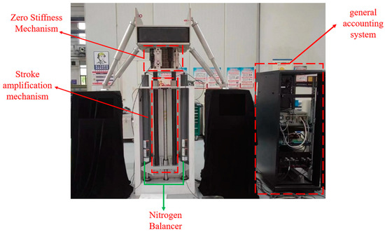
Figure 8.
Microgravity simulation system.
4.1. Creation of a Microgravity Simulator
The stroke amplification mechanism is mainly composed of a servo motor, synchronous belt, drive screw, and linear guide bar. The servo motor SGD7S-550A made by Yaskawa (Kitakyushu, Japan) with a power of 7.5 kW, a rated torque of 48 N m, and a rated speed of 1500 rpm; the transmission ratio of the synchronous belt is 1:1; the total stroke of the drive screw is 480 mm and the guide stroke is 50 mm; the maximum vertical speed of this mechanism is 1250 mm/s; and the positioning accuracy and repetition accuracy of this mechanism is better than 1.0 mm. To meet the demand of large-load spacecraft, the compensating force is provided by a Pascal nitrogen balancer, which can provide stable balancing force with small pressure change and can reduce the load of the screw to suppress the heat generation. The integrated control system transforms the Windows system into a hard real-time system by installing the RTX real-time system on the Windows 7 system. The Windows system runs the MFC human–machine interface, and the RTX system runs the servo control program in real time. Both of them interact with each other in real time through the shared memory without interfering with each other. The clock resolution of RTX can reach 100 nanoseconds, and the timer period can be as low as 1000, 500, 200, and 100 microseconds, which ensures the high-speed operation of the servo algorithm. Prior to the start of the test, the spacecraft is balanced by adjusting the nitrogen balancer and the stiffness of the QZS mechanism. When an external excitation is applied, the servo system follows the motion of the spacecraft in real time, thus realizing the motion state of the spacecraft in a microgravity environment.
The experimental process is as follows: before the experiment begins, the valve controlling the gas needs to be opened and the various parts of the experimental operating system need to be checked for normal operation. At the beginning of the experiment, the space simulator is first raised to the target position using a servo motor, and the displacement of the grating ruler is observed on the system operation interface. When the displacement of the grating ruler stabilizes and tends towards zero, the constant force following phase begins: Place the weight on the spacecraft, and the grating ruler will undergo a small displacement change. The servo motor will enter a constant force following mode to ensure that the displacement change of the grating ruler tends towards a stable state. When the entire space simulator lands stably on the landing surface, the motor is controlled to stop moving through the system operation interface. Repeat the above experimental steps until the different external stimuli are tested and the system stops.
4.2. Analysis and Discussion of Test Results
We verify the correctness of the simulation model and the theoretical model through experiments, and compare and analyze the experimental data with the theoretical model.
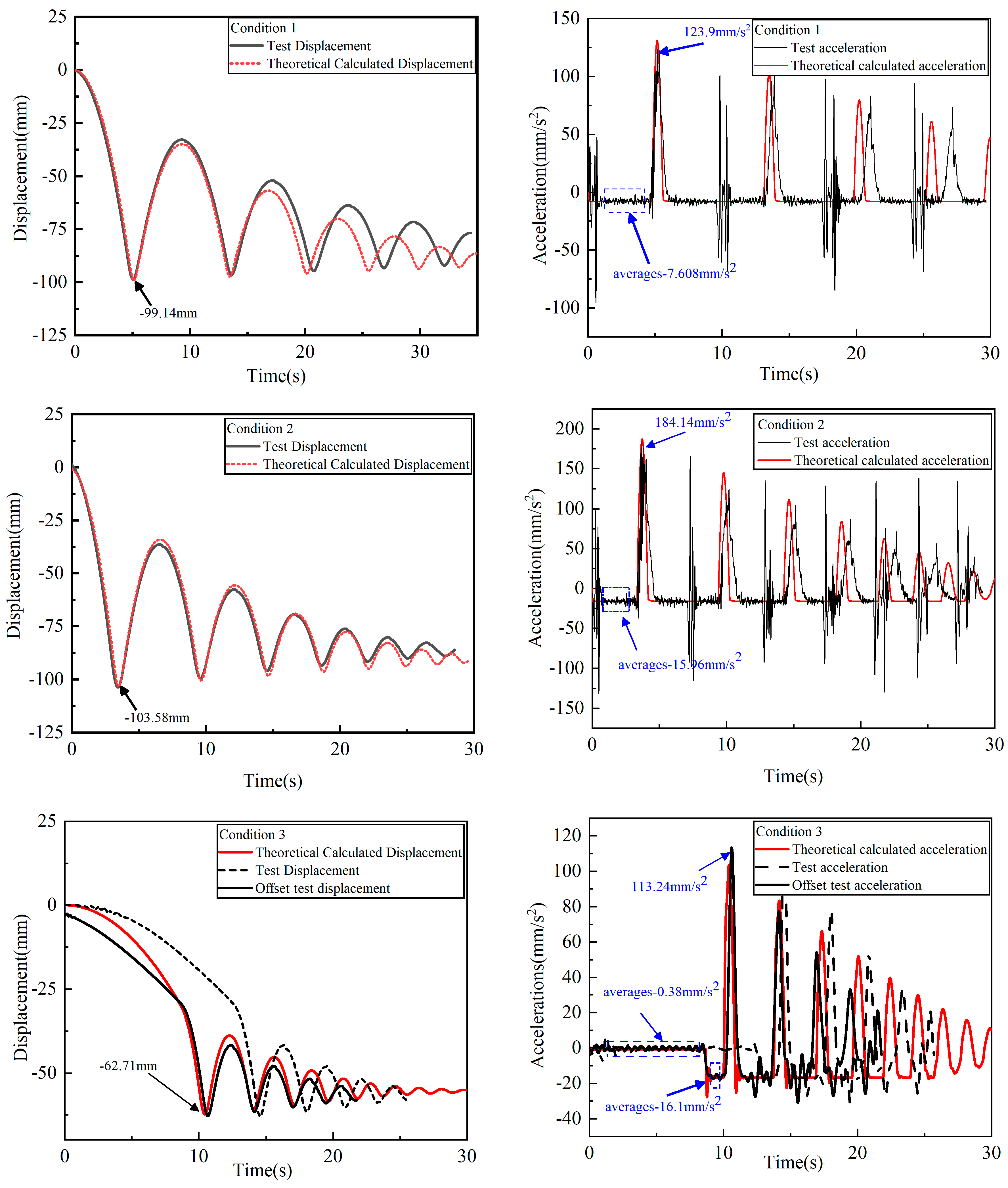
Analyzing the above images, the displacement image shows that the microgravity simulation system well embodies the jumping behavior of the lander in a microgravity environment. The acceleration images show that the spacecraft is slightly vibrating during the free-fall process, which is due to the low stiffness of the QZS mechanism. In addition to the sudden change in acceleration at the moment of collision, the spacecraft also has an obvious sudden change in acceleration during servo motor commutation, which is a phenomenon due to the poor robustness of the PID control strategy and the limited control accuracy. The first displacement curve and the collision acceleration curve are in relative agreement. The difference between the ground test system and the kinetic model kinematics results in a poorer match for the subsequent contact collision process. Table 4, Table 5 and Table 6 show the error between the test and simulation results.
Table 4.
Results of theoretical and actual descent accelerations.
Table 5.
Results of theoretical and actual deformation.
Table 6.
Results of theoretical and actual collision acceleration.
With the data in Table 4, the compensation accuracies for Test Case 1 and Test Case 2 were as high as 97.1% and 99.7%. The free-fall acceleration in the first stage of test condition 3 was −0.38 mm/s2, which was 0.42 mm/s2 different from the theoretical acceleration, resulting in a lag of 3.9 s between the displacement and acceleration curves. This phenomenon is caused by the fact that the external excitation of 50 g has a small effect compared to the external disturbing force, and the PID control strategy is not able to recognize the inputs accurately. However, after adding 1 kg of external excitation in the second stage, the relative error was reduced to 4.22%, which verified the correctness of the above statement. The data from the first phase of Test Case 3 show that the microgravity simulation system can simulate up to 10−4 g, while the control strategy needs to be improved accordingly to reduce the influence of external disturbances. The relative errors of the test conditions are shown in Table 4, Table 5 and Table 6, and the results prove that the relative error of condition 3 is the largest.
From the comparison between theoretical models and experiments, it can be concluded that the curve of the first collision process is in good agreement, which verifies the accuracy of the theoretical modeling. However, the accuracy of gravity compensation and the accuracy during collision are relatively poor compared to the literature [27]. This is because the load mass in this article is 620 kg, and there may be significant disturbances and changes in the compensation force, but the compensation accuracy is still acceptable. From Figure 9, it can be seen that there is a temporal shift in the subsequent collision bounce process, and the larger the collision force, the more obvious the phenomenon of landing time shift. This phenomenon is partly caused by the accumulation of errors, and partly due to the poor response of classical PID control strategies to collision impact moments. Further improvement of the control strategy is needed, which is also the focus of subsequent research in this article.
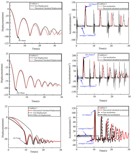
Figure 9.
Comparison of test results with simulation results.
5. Conclusions
This paper establishes a theoretical model of the collision dynamics of the foot in contact with a high elastic body, builds a microgravity system simulation platform, studies the collision characteristics of a heavy-lift spacecraft in different microgravity environments, and draws the following conclusions through simulation and experimental verification:
- Comparing Cases 1–3, the displacement change of the flexible unit at the moment of collision is only 0.3 μm, and the change of the output constant force of the QZS mechanism is approximated to be 0. It is verified that the QZS mechanism can still show superior cushioning performance and compensation performance in the process of landing detection.
- The correctness of the collision dynamics model was verified by theory and experiment. The experimental data of Case 1 show that the microgravity simulation system can compensate the gravity up to 10−3 g, and the compensation accuracy is 97.1%. The experimental data of Case 2 show that the microgravity simulation system can compensate the gravity up to 10−2 g, and the compensation accuracy is 99.7%. In Case 3, it is verified that the spacecraft still jumps when the external excitation is added with an additional 1 kg at the moment of the spacecraft’s contact with the ground, but the height of the jump is significantly reduced. With a smaller load excitation of 50 g, the compensation accuracy of the microgravity simulation system is unstable, but the microgravity level can still be simulated up to 10−4 g, and the compensation accuracy is 95.78%, indicating that the control strategy needs to be further optimized.
- Optimization suggestions for control strategies: By utilizing machine learning algorithms such as deep learning and reinforcement learning, the collision forces obtained from learning models and experimental calculations, as well as the dynamic response of spacecraft, can be automatically adjusted to the control parameters during the collision process, thereby improving the robustness and sensitivity of the system. In addition, the PID control algorithm with priority differentiation can also be adopted by transferring the differential action to the feedback loop, that is, differentiating only the controlled variable without differentiating the input deviation, thereby reducing the direct impact of the rise and fall of the given value on the system. This method is suitable for solving the impact problem caused by collisions on the system.
- Comparison of the values of the collision acceleration as well as the maximum deformation leads to a more accurate kinetic modeling of the contact force model. The simulation curves match the test curves to a more consistent degree, and a large deviation occurs in the first stage of Case 3, indicating that the sensitivity of the QZS mechanism may not be able to recognize a load of 50 g, which is an issue that needs to be explored in depth.
Author Contributions
Conceptualization, Z.J. and Y.L.; methodology, W.H. and Y.L.; software, Z.J. and B.G.; validation, L.Z. and H.Z.; formal analysis, B.Z., H.L. and Y.C.; investigation, Z.J. and W.H.; data curation, Z.J.; writing—original draft preparation, Z.J.; writing—review and editing, Y.A. and H.Z.; visualization, L.Z. and Z.J.; supervision, L.Z. and Q.H.; project administration, W.H. and B.Z.; funding acquisition, W.H. All authors have read and agreed to the published version of the manuscript.
Funding
This research was supported by the National Natural Science Foundation of China (52475249), the China Postdoctoral Science Foundation under Grant Number 2024M752383, the National Natural Science Foundation of China (52305102), the National Natural Science Foundation of China (U21B2075), the National Key R&D Program of China (2023YFC2205900, 2023YFC2205903, 2023YFC2205904), the Reusable Space Debris Capture and Removal Project (KJSP2020010302), the Stable Supporting Fund of National Key Laboratory of Underwater Acoustic Technology (JCKYS2023604SSJS012), the Fundamental Research Funds for the Central Universities (3072023WD070101), the National Natural Science Foundation of China (52375025).
Data Availability Statement
The original contributions presented in the study are included in the article material; further inquiries can be directed to the authors.
Acknowledgments
We give thanks to the Tianjin Aerospace Electromechanical Equipment Research Institute for their financial and equipment support for this project.
Conflicts of Interest
The authors declare no conflicts of interest.
References
- Zhang, J.; Dong, C.; Zhang, H.; Li, S.; Song, A. Modeling and Experimental Validation of Sawing Based Lander Anchoring and Sampling Methods for Asteroid Exploration. Adv. Space Res. 2018, 61, 2426–2443. [Google Scholar] [CrossRef]
- Anthony, N.; Emami, M.R. Asteroid Engineering: The State-of-the-Art of Near-Earth Asteroids Science and Technology. Prog. Aerosp. Sci. 2018, 100, 1–17. [Google Scholar] [CrossRef]
- Ramos, J.A.P.; Luis, F.R.R.D. Resources in Space and Asteroid Mining: Where We Are and Which Challenges Should Be Expected. Int. J. Technol. Manag. 2020, 82, 197. [Google Scholar] [CrossRef]
- Landis, M.E.; Byrne, S.; Combe, J.-P.; Marchi, S.; Castillo-Rogez, J.; Sizemore, H.G.; Schörghofer, N.; Prettyman, T.H.; Hayne, P.O.; Raymond, C.A.; et al. Water Vapor Contribution to Ceres’ Exosphere from Observed Surface Ice and Postulated Ice-Exposing Impacts. J. Geophys. Res. Planets 2019, 124, 61–75. [Google Scholar] [CrossRef]
- Yu, Z.; Zhu, S.; Cui, P.; Liu, Y. Research Progress of Small Body Surface Motion Technologies. J. Deep Space Explor. 2017, 4, 301–309. [Google Scholar] [CrossRef]
- Zhang, Y.; Zeng, X.; Circi, C.; Vulpetti, G. The Motion of Surface Particles for the Asteroid 101955 Bennu. Acta Astronaut. 2019, 163, 3–10. [Google Scholar] [CrossRef]
- Ma, J.; Dong, S.; Chen, G.; Peng, P.; Qian, L. A Data-Driven Normal Contact Force Model Based on Artificial Neural Network for Complex Contacting Surfaces. Mech. Syst. Signal Process. 2021, 156, 107612. [Google Scholar] [CrossRef]
- Lan, G.; Sun, W.; Zhang, X.; Chen, Y.; Tan, W.; Li, X. A Three-Dimensional Fractal Model of the Normal Contact Characteristics of Two Contacting Rough Surfaces. AIP Adv. 2021, 11, 055023. [Google Scholar] [CrossRef]
- Liu, Y.; Wang, Y.; Chen, X.; Yu, H. A Spherical Conformal Contact Model Considering Frictional and Microscopic Factors Based on Fractal Theory. Chaos Solitons Fractals 2018, 111, 96–107. [Google Scholar] [CrossRef]
- Li, X.; Yue, B.; Wang, D.; Liang, Y.; Sun, D. Dynamic Characteristics of Cylinders’ Joint Surfaces Considering Friction and Elastic–Plastic Deformation Based on Fractal Theory. Aust. J. Mech. Eng. 2017, 15, 11–18. [Google Scholar] [CrossRef]
- Machado, M.; Moreira, P.; Flores, P.; Lankarani, H.M. Compliant Contact Force Models in Multibody Dynamics: Evolution of the Hertz Contact Theory. Mech. Mach. Theory 2012, 53, 99–121. [Google Scholar] [CrossRef]
- Hunt, K.H.; Crossley, F.R.E. Coefficient of Restitution Interpreted as Damping in Vibroimpact. J. Appl. Mech. 1975, 42, 440–445. [Google Scholar] [CrossRef]
- Hu, S.; Guo, X. A Dissipative Contact Force Model for Impact Analysis in Multibody Dynamics. Multibody Syst. Dyn. 2015, 35, 131–151. [Google Scholar] [CrossRef]
- Shen, Y.; Xiang, D.; Wang, X.; Jiang, L.; Wei, Y. A Contact Force Model Considering Constant External Forces for Impact Analysis in Multibody Dynamics. Multibody Syst. Dyn. 2018, 44, 397–419. [Google Scholar] [CrossRef]
- Zhang, J.; Li, W.; Zhao, L.; He, G. A Continuous Contact Force Model for Impact Analysis in Multibody Dynamics. Mech. Mach. Theory 2020, 153, 103946. [Google Scholar] [CrossRef]
- Zhang, Y.; Sharf, I. Validation of Nonlinear Viscoelastic Contact Force Models for Low Speed Impact. J. Appl. Mech. 2009, 76, 051002. [Google Scholar] [CrossRef]
- Wu, Q.; Feng, X.; Chen, Y.; Liu, M.; Bao, X. Continuous Medium Chain Carboxylic Acids Production from Excess Sludge by Granular Chain-Elongation Process. J. Hazard. Mater. 2021, 402, 123471. [Google Scholar] [CrossRef]
- Rosas, A.; Romero, A.H.; Nesterenko, V.F.; Lindenberg, K. Observation of Two-Wave Structure in Strongly Nonlinear Dissipative Granular Chains. Phys. Rev. Lett. 2007, 98, 164301. [Google Scholar] [CrossRef]
- Flores, P. A Parametric Study on the Dynamic Response of Planar Multibody Systems with Multiple Clearance Joints. Nonlinear Dyn. 2010, 61, 633–653. [Google Scholar] [CrossRef]
- Flores, P.; Ambrósio, J.; Claro, J.P. Dynamic Analysis for Planar Multibody Mechanical Systems with Lubricated Joints. Multibody Syst. Dyn. 2004, 12, 47–74. [Google Scholar] [CrossRef]
- Kufner, E.; Blum, J.; Callens, N.; Eigenbrod, C.; Koudelka, O.; Orr, A.; Rosa, C.C.; Vedernikov, A.; Will, S.; Reimann, J.; et al. ESA’s Drop Tower Utilisation Activities 2000 to 2011. Microgravity Sci. Technol. 2011, 23, 409–425. [Google Scholar] [CrossRef]
- Carignan, C.R.; Akin, D.L. The reaction stabilization of on-orbit robots. IEEE Control. Syst. Mag. 2000, 20, 19–33. [Google Scholar]
- Santaguida, L.; Zhu, Z.H. Development of Air-Bearing Microgravity Testbed for Autonomous Spacecraft Rendezvous and Robotic Capture Control of a Free-Floating Target. Acta Astronaut. 2023, 203, 319–328. [Google Scholar] [CrossRef]
- Witte, L.; Schroeder, S.; Kempe, H.; van Zoest, T.; Roll, R.; Ulamec, S.; Biele, J.; Block, J. Experimental Investigations of the Comet Lander Philae Touchdown Dynamics. J. Spacecr. Rocket. 2014, 51, 1885–1894. [Google Scholar] [CrossRef]
- Kolvenbach, H.; Hampp, E.; Barton, P.; Zenkl, R.; Hutter, M. Towards Jumping Locomotion for Quadruped Robots on the Moon. In Proceedings of the 2019 IEEE/RSJ International Conference on Intelligent Robots and Systems (IROS), Macau, China, 3–8 November 2019; pp. 5459–5466. [Google Scholar]
- Liu, Z.; Niu, F.; Gao, H.; Yu, H.; Ding, L.; Li, N.; Deng, Z. Design, Analysis, and Experimental Validation of an Active Constant-Force System Based on a Low-Stiffness Mechanism. Mech. Mach. Theory 2018, 130, 1–26. [Google Scholar] [CrossRef]
- Zhou, R.; Zhou, Y.; Chen, X.; Hou, W.; Wang, C.; Wang, H.; Jiang, W. Gravity compensation method via magnetic quasi-zero stiffness combined with a quasi-zero deformation control strategy. Sci. China Technol. Sci. 2022, 65, 1738–1748. [Google Scholar] [CrossRef]
- Hou, W.; Hao, Y.; Wang, C.; Chen, L.; Li, G.; Zhao, B.; Wang, H.; Wei, Q.; Xu, S.; Feng, K.; et al. Theoretical and Experimental Investigations on High-Precision Micro-Low-Gravity Simulation Technology for Lunar Mobile Vehicle. Sensors 2023, 23, 3458. [Google Scholar] [CrossRef]
- Xu, K.-F.; Niu, M.-Q.; Zhang, Y.-W.; Meng, C.-Y.; Chen, L.-Q. A Nonlinear Energy Sink Enhanced by Active Varying Stiffness for Spacecraft Structure: Theory, Simulation, and Experiment. Mech. Syst. Signal Process. 2023, 204, 110787. [Google Scholar] [CrossRef]
Disclaimer/Publisher’s Note: The statements, opinions and data contained in all publications are solely those of the individual author(s) and contributor(s) and not of MDPI and/or the editor(s). MDPI and/or the editor(s) disclaim responsibility for any injury to people or property resulting from any ideas, methods, instructions or products referred to in the content. |
© 2024 by the authors. Licensee MDPI, Basel, Switzerland. This article is an open access article distributed under the terms and conditions of the Creative Commons Attribution (CC BY) license (https://creativecommons.org/licenses/by/4.0/).