Article

Development of a Magnetorheological Damper with Self-Powered Ability for Washing Machines

1
Faculty of Civil Engineering, Ho Chi Minh City University of Technology and Education, Ho Chi Minh City 71307, Vietnam
2
Faculty of Mechanical Engineering, Industrial University of Ho Chi Minh City, Ho Chi Minh City 71408, Vietnam
3
Division of Computational Mechatronics, Institute for Computational Science, Ton Duc Thang University, Ho Chi Minh City 758307, Vietnam
4
Faculty of Electrical & Electronics Engineering, Ton Duc Thang University, Ho Chi Minh City 758307, Vietnam
5
Faculty of Engineering, Vietnamese-German University, Binh Duong Province 75114, Vietnam
6
Faculty of Mechanical Engineering, Ho Chi Minh City University of Technology and Education, Ho Chi Minh City 71307, Vietnam
*
Author to whom correspondence should be addressed.
Appl. Sci. 2020, 10(12), 4099; https://doi.org/10.3390/app10124099
Submission received: 9 May 2020 / Revised: 6 June 2020 / Accepted: 10 June 2020 / Published: 14 June 2020
(This article belongs to the Section Mechanical Engineering)

Abstract

:
Magnetorheological (MR) dampers have been widely investigated and proposed for vibration mitigation systems because they possess continuous variability of damping coefficient in response to different operating conditions. In the conventional design of MR dampers, a separate controller and power supply are required, causing an increment of complexity and cost, which are not suitable for home appliances like washing machines. To solve these issues and to reuse wasted energy from vibration of washing machines, in this study, a self-powered shear-mode MR damper, which integrates MR damping and energy-harvesting technologies into a single device, is proposed. The MR damper is composed of an inner housing, on which magnetic coils are wound directly, and an outer housing for covering and creating a closed magnetic circuit of the damper. The gap between the inner housing and the moving shaft is filled with MR fluid to produce the damping force. The energy-harvesting part consists of permanent magnets fastened together on the shaft and induction coils wound directly on slots of the housing. The induced power from the induction coils is directly applied to the excitation coils of the damping part to generate a corresponding damping force against the vibration. In order to achieve optimal geometry of the self-powered MR damper, an optimization for both the damping part and the energy harvesting part of the proposed dampers are conducted based on ANSYS finite element analysis. From optimal solutions, a prototype of the proposed damper is designed in detail, manufactured, and experimentally validated.

1. Introduction

Semiactive suspension systems have been widely used in the field of vibration control [1]. Since the 1990s, magnetorheological (MR) dampers have been promisingly studied for these systems due to their attractive features such as high damping force, good adaptability, continuous controllability, and high reliability. MR dampers can be increasingly applied in industrial environments of civil structures [2], automobiles [3], and precision machines [4]. One of the particularly interested applications of MR dampers is to attenuate vibration of washing machines. The distribution of the laundry in the washing drum is often out of balance causing the vibration of washing machines. It is found that during spinning process, the washing machine usually experiences the first resonance at quite low frequency, around 100–200 rpm [5,6,7]. This resonance comes from the rigid vibration mode of the washing drum. When the spindle speed exceeds 1000 rpm, such as in spinning stage, resonances can appear at the rear and side frame panels bringing about noises, uncomfortable feelings, and the shortening of the washing machine life span. The dampers in conventional suspension systems could provide passive damping forces to well eliminate the vibration at low frequency of resonance but raise the force transmissibility at high excitation frequencies because the damping coefficient could not be changed. Therefore, to effectively mitigate the vibration of washing machines at low frequency of resonance while it is still well isolated at high excitation frequencies, semiactive suspension systems that can continuously control the damping coefficient such as MR dampers-based vibration control systems should be employed (Figure 1).
Although several studies on MR dampers have been performed to control the vibration of washing machines [8,9], optimal design of these MR dampers was not considered. Nguyen et al. [10] conducted optimal design of a small MR damper in flow-mode for washing machines. The results showed that size of the optimized MR damper is well fit for integration in washing machines to replace conventional ones. The maximum damping force was up to 150 N, which is greater than expected damping force for MR damper (from 80 to 100 N). However, off-state force of the damper was quite high, around 25 N. Later, Nguyen et al. [11] proposed a new shear-mode configuration of MR damper for washing machines. The optimal results indicated that the proposed shear-mode MR damper was able to generate a damping force of about 120 N with much smaller off-state force, around 10 N. It was also pointed out that the proposed damper can be well installed in washing machines to replace conventional dampers. In addition, no bobbin for coils is used, which facilitate the manufacturing. However, no experimental works was conducted in this research. Recently, Bui et al. [12] performed a research on optimal design of MR dampers for front-loaded washing machines, considering expected damping forces, assembly space, power consumption, and cost as an extension of study carried out by [11]. In addition, experimental works on performance characteristics of the damper and effectiveness of implementation of the damper in a prototype washing machine was also implemented. The research results showed a good correlation between the experimental performance and theoretical simulation. Similarly, Ulasyar and Lazoglu [13] developed a MR sponge damper for washing machines with design optimization of geometric parameters; however, stability and lastingness of the sponge are considerable issues. Although the above semiactive systems can well solve the problem of washing machine vibration control, they require auxiliary equipment such as sensors, control units, and power sources to enable the operation. This makes the systems more complicated and difficult for maintenance with high production cost. Another drawback of the semiactive vibration control systems is that the vibration energy is wasted on wearing and heating rather than recovering it to power the dampers. Inspired by those issues, there has been a great deal of research efforts in exploring the area of energy harvesting for MR dampers. Cho et al. [14] proposed a smart passive control system consisting of an MR damper and an electromagnetic induction (EMI) device. Then, Choi et al. [15] and Kim et al. [16] studied the realization of this system by experimental works. However, in this smart passive system, the energy-harvesting part is designed apart from the MR damper, so the whole size of the system would be increased and may not be available for small installation spaces such as those in washing machines.
Consequently, this paper aims at the investigation of a self-powered MR damper for the suspension system of washing machines. The self-powered MR damper integrates MR damping part and energy-harvesting part into a single device in order to enable the MR damper to reuse the wasted mechanical energy from vibration for self-power, and also, it can be well installed in washing machines. Configuration of the damping part is similar to that in previous research [11,12]. The energy-harvesting part is based on electromagnetic induction featuring permanent magnets and arrays of coils. With the energy-harvesting part added to the MR damper, the greater the vibration of the damper shaft is, the higher the power is generated, and the damping level is automatically commanded. As a result, the proposed control system can smartly adapt to external excitations by itself without any sensors and controllers, which can improve complexity and cost of the suspension system. After the configuration of the self-powered MR damper is proposed, an optimization procedure is conducted for both the damping part and the energy harvesting part of the damper. From the optimal solutions, a prototype of the proposed damper is designed and manufactured. The performance of each part and the whole damper are then investigated by both simulation and experiment.

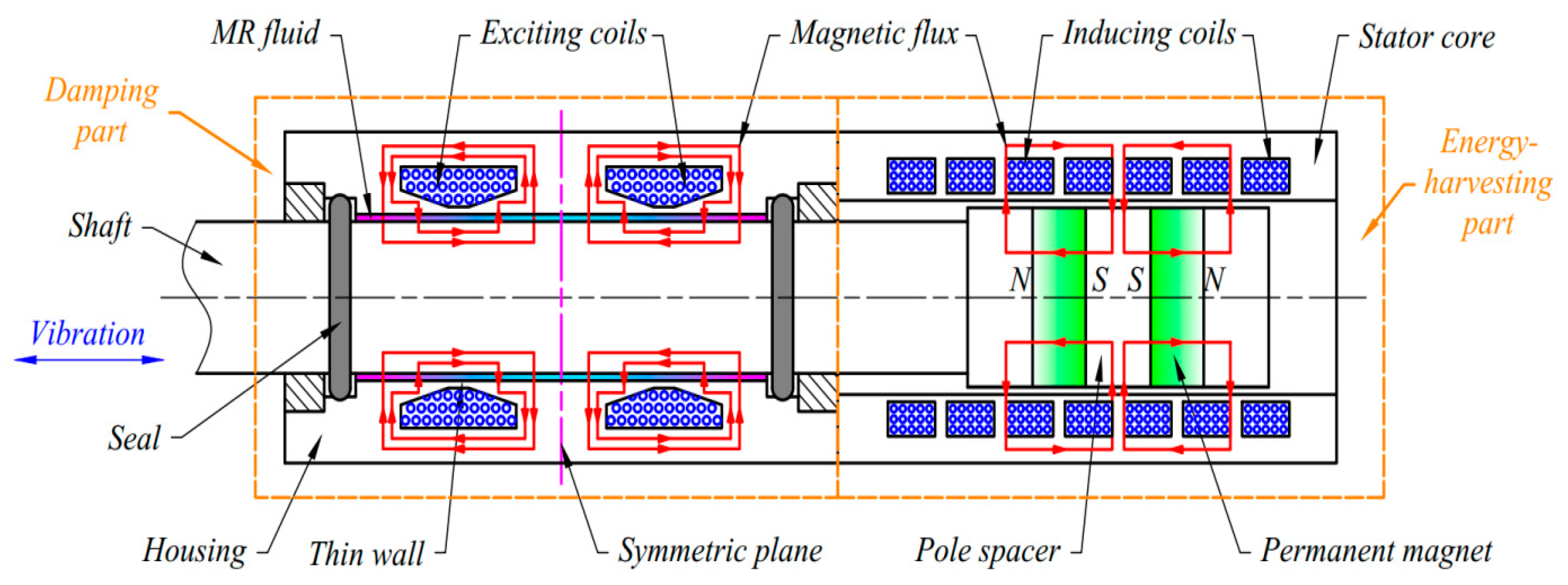
2. Configuration and Operating Principles

MR dampers typically operate in three modes: shear, flow, and mixed modes (the combination of the first two modes). The flow and mixed modes of MR dampers can provide high damping because of the pressure generated in the lower and upper chambers. However, they are more complicated and have higher cost than the shear-mode due to a large amount of MR fluid used in the chambers. It is noteworthy that washing machines do not require a so high damping force, but the zero-field friction force needs to be as small as possible to suppress the force transmissibility at high frequencies. Consequently, the shear-mode is implemented in our study. The schematic of the proposed self-powered MR damper in shear-mode is shown in Figure 2. As shown in the figure, the shaft of damper moves reciprocally due to the vibration of washing machines, developing damping force via direct shearing of the MR fluid. With this configuration, the interaction of the magnetic field between the damping and energy-harvesting parts could be diminished.
Compared with conventional MR dampers, the self-powered shear-mode MR damper is able to adapt itself based on the mechanical energy produced from its working process via an energy-harvesting vibration absorber. In general, the self-powered MR damper consists of two main components: the MR damping part and the energy-harvesting one. The MR damping part is composed of an inner housing with a thin wall, on which the exciting coils are wound directly, and an outer housing for covering and creating a closed magnetic circuit of the damper. The MR fluid is fully injected into the gap between the shaft and inner housing. The cross-section area of the thin wall is built to be as small as possible for a quick magnetic saturation of the flux lines. As a result, the magnetic flux is compelled to move across the MR fluid gap. In addition, appropriate chamfers are added to the cross-section of the coils to maximize this magnetic flux. When a magnetic field is applied, the solidification of the MR fluid occurs, and the damping force is produced from the friction between the housing and the shaft. In some researches, the MR damper could be designed with more exciting coils to improve the damping effectiveness. However, this lengthens the damper, which may not satisfy the installation space in washing machines. Furthermore, the more coils are used, the more exciting powers are demanded, which leads to high heat emission and more maintenance cost. Considering the above problems, the design with two exciting coils is proposed for the MR damping part.
The energy-harvesting (EH) part consists of magnetized permanent magnets and pole spacers alternately fastened together on the moving shaft and a slotted stator core covered by an outer housing. In this paper, the linear multipole type is proposed for the configuration of the EH part. One magnet and one adjacent pole spacer are grouped into one pole pair. The magnets are ring-shaped and possess axial magnetization; thus, they are placed in cross-pole positions to force the flux going through the spacers and across the air gap. The inducing coils are wound directly on the slots of the stator core and connected to the exciting coils of the damping part. Under linear excitations caused by the vibration of washing machines, the relative movement between the magnets mounted on the shaft end and the stator core appears. This results in an induced electric power supplied to the MR damping part.

3. Energy-Harvesting Part

In this section, the EH part is designed to power the MR damping part. Based on the principle of electromagnetic induction, the EH part will convert the kinetic energy resulting from vibration into electricity for the exciting coils of the MR damping part.

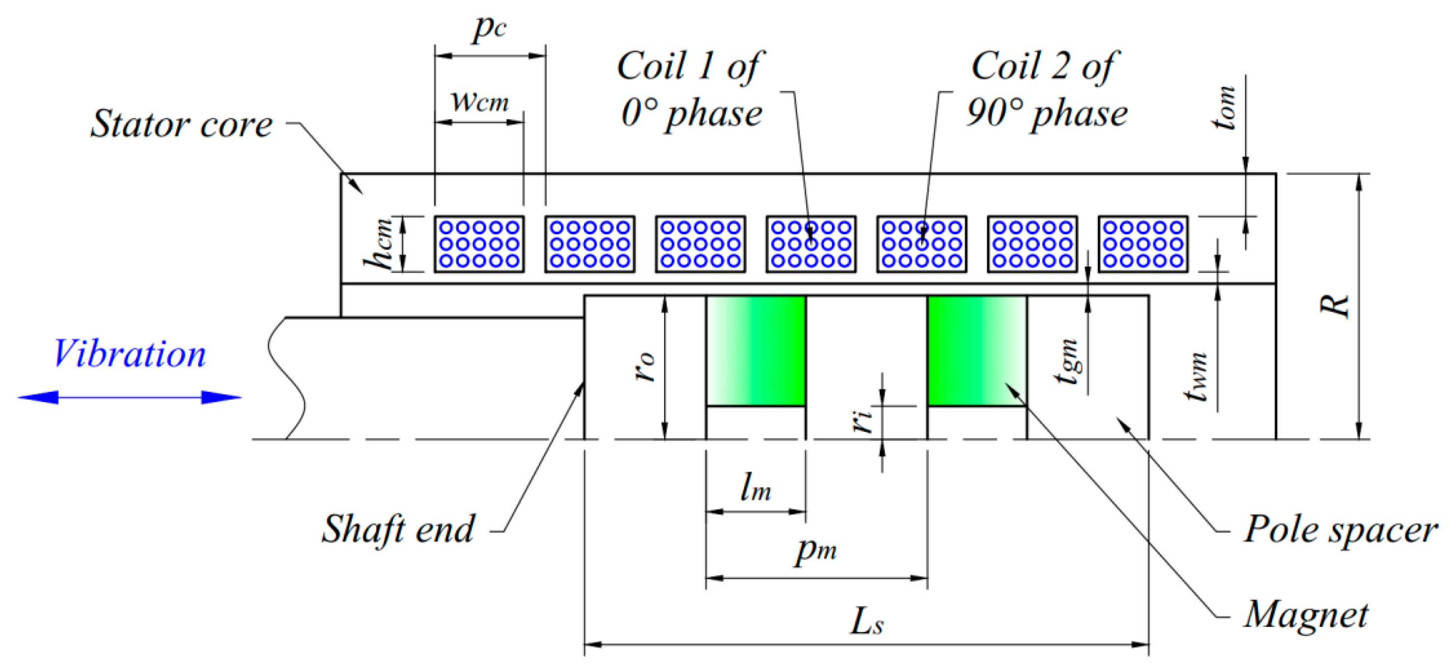
3.1. Modeling of the Energy-Harvesting Part

Figure 3 shows the schematic of the EH part. The pole spacers and stator core are made of commercial C45 steel, which is a common material with high magnetic permeability. The NdFeB grade N35 ring-shaped magnets are fitted on an aluminum shaft end alternately with the pole spacers. The magnet has an outer diameter of 28 mm, an inner diameter of 6 mm, and a length of 7 mm. In our research, the prototype front-loaded washing machine is the WF8690NGW washing machine produced by Samsung Electronics Co., Ltd., Seoul, Korea. Considering the available assembly space of dampers in the washing machine, the number of magnets and coils on the stator core are chosen to be 2 and 7, respectively. In this way, the maximum number of coils in the electromagnetic working state will be 4 out of 7 coils.
By neglecting the reluctance of pole spacers and stator core, the magnetic flux of the cylindrical air gap between the magnets and the stator core Φg is given as [17,18,19,20]
Φ g = λ B r e m l m μ 0 H c o e A g m 2 t g m B r e m + l m μ 0 H c o e ( A g m / A m )
where λ expresses the efficiency of the magnetic flux considering leakage effect, Brem characterizes the magnet remanent flux density, Hcoe denotes the magnetic coercivity of the magnet, µ0 represents the relative magnetic permeability and is equal to 4π × 10−7 N/A2, lm is the length of the magnet, tgm is the thickness of the air gap, Agm is the cylindrical surface area of the air gap, and Am is the sectional area of the magnet. Agm and Am can be determined by
A g m = 2 π ( r o + t g m 2 ) ( p m l m 2 )
A m = π ( r o 2 r i 2 )
where ri and ro are the inner and outer radii of magnet, respectively, and pm is the pitch of the pole pair. The induced voltage E in the inducing coil is defined as
E = N Φ g π p m sin ( π p m x + φ 0 ) d x d t
where x and d x d t are the displacement and velocity of the shaft, respectively, and φ0 is the initial phase angle of the inducing coil. The number of winding turns of each inducing coil N is calculated by [17]
N = 2 A c 3 d w 2
where dw is the diameter of the copper wire and Ac is the cross-sectional area of the coil determined by the product of the coil height hcm and the coil width wcm. Since the pitch of the pole pair pm is designed to double the pitch of the coil slot pcm, the phase angle is π/2 between each nearby coil. Accordingly, the induced voltages in four active coils are
E 1 = N Φ g π p m sin ( π p m x ) d x d t
E 2 = N Φ g π p m cos ( π p m x ) d x d t
E 3 = E 1
E 4 = E 2
In case of low excitation frequencies, by neglecting the coil inductance, the coil is supposed to work as a resistor. The power of four active coils P is obtained by
P = 2 ( P 1 + P 2 ) = 2 ( E 1 2 R c + E 2 2 R c ) = 2 ( N Φ g π p m ) 2 R c v 2
where P1 and P2 are the powers of coils 1 and 2, respectively; Rc is the resistance of each coil; and v is the velocity of the shaft. Equation (10) describes the generated power of four active coils as a quadratic function of the excitation velocity. From the equation, it is also observed that geometric dimensions of the stator core and the pole spacers considerably affect the power magnitude. Consequently, to achieve the best performance of power generation, an optimization procedure for the design of the EH part should be implemented.

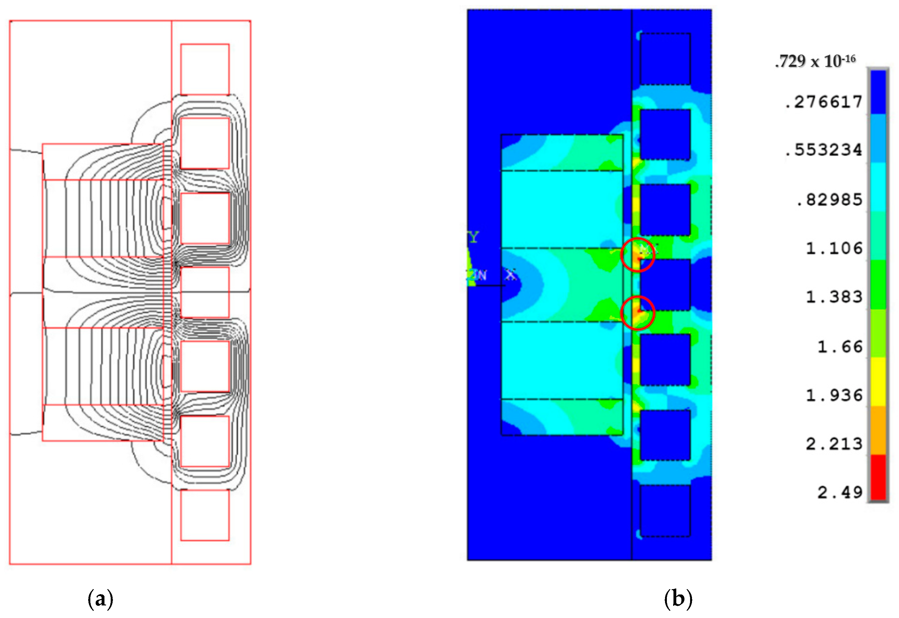
3.2. Optimal Design of the Energy-Harvesting Part
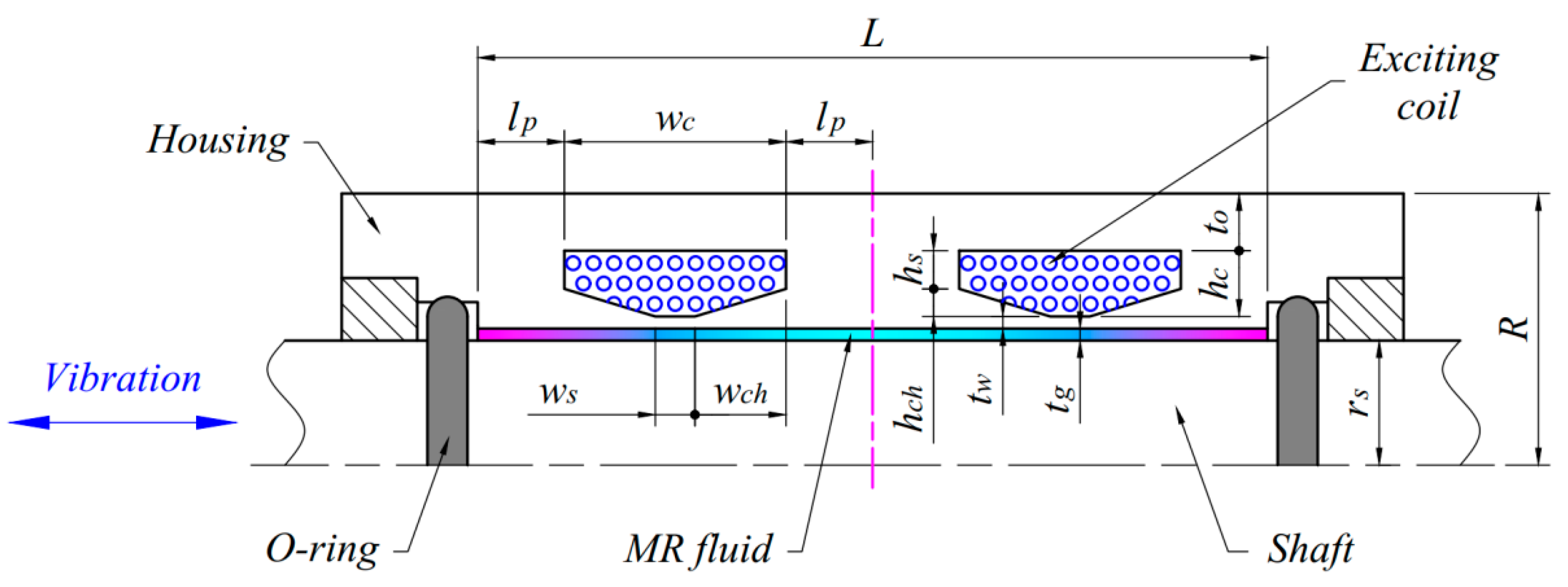
As mentioned above, the generated power in Equation (10) should be as large as possible to maximize the efficiency of the EH part. In the design of the EH part, the height of coil hcm, the width of coil wcm, the pitch of coil pc, the pitch of pole pair pm, and the thickness of housing tom are significant dimensions and thus set as design variables. Another problem that should be considered is the available assembly space in the washing machine. Since the total length of the damper in equilibrium is approximately 230 mm and the desired maximum damper stroke is established by 40 mm, the length of the shaft end carrying the pole pairs Ls is restricted to be smaller than 30 mm. From the aspects of compactness and low cost, it would not be ideal to improve the possibility of generating power by increasing the EH part size. Therefore, although the outer radius of the EH part has no restriction, it should not be so much larger than that of commercial passive dampers and conventional MR dampers. In this optimization, the value of 22 mm is chosen to be the upper limit of radius R of the EH part. The final concern is the possibility of machining and assembling the stator core without warping, for which the thickness of the housing tom is set to be 2 mm or greater. In summary, the design optimization of the EH part can be expressed: Determine the optimal geometry of the proposed EH part that maximize the generated power, subjected to the outer radius R is smaller than 22 mm and the length of the shaft end Ls is smaller than 30 mm.
In this work, the finite element model of the EH part is implemented using the 2D-axisymmetric couple element (plane 13) of ANSYS. It is noteworthy that the geometry of the EH part will continuously vary during the optimization process, so the meshing size is defined by the constant number of elements per line rather than the size of each element. Figure 4 shows the finite element model of the EH part. In order to obtain the optimal design of the EH part, the golden section algorithm combined with first-order method of the ANSYS optimization tool is utilized. The procedure in detail based on finite element analysis (FEA) has been presented in some researches [21,22].
The optimal solution of the proposed EH part is specified in Table 1. It is noted that the thicknesses of the air gap tgm and thin wall twm should be as small as possible. In this study, both are set by 0.8 mm considering the manufacturing cost. Figure 5a,b shows the magnetic flux distribution and magnetic flux density of the optimized EH part, respectively. From Figure 5a, it is observed that the magnetic flux passes through the air gap between the magnets and the stator core. As a result, the induced voltages could be generated in the inducing coils of the EH part to power the exciting coils of the MR damping part. Besides, there is almost a saturation of magnetic flux toward the south poles of the magnets, which is marked in Figure 5b.

4. MR Damping Part

4.1. Modeling of the MR Damping Part

The MR damping part is coaxial with and in front of the EH part. Figure 6 shows the schematic diagram of the shear-mode MR damping part. The shaft and the housing are made of C45 steel. The O-rings made of 70-durometer NBR rubber are used to seal the MR fluid.
In the design of MR damper-based devices, the damping forces should be first established as functions of the applied magnetic field and geometric dimensions. For the proposed MR damping part illustrated in Figure 6, it is supposed that if the MR fluid velocity in the gap between the housing and the shaft is linear, then the generated damping force Fd and zero-field friction force F0 are defined by
F d = 2 π r s L e ( τ y + η v t g ) + 2 F o r
F 0 = 2 π r s L ( τ y 0 + η 0 v t g ) + 2 F o r
where Rs is the shaft radius; tg is the MR fluid gap thickness; v is the velocity between the housing and the shaft; τy and η are the yield stress and post-yield viscosity of the active MR fluid in the gap, respectively; L is the MR fluid gap length; and Le is the effective length of the active MR fluid in the gap. In this configuration, Le ≈ L. The Coulomb friction force For between the O-ring and the shaft can be determined by [23]
F o r = f c L r + f h A r
where Lr is the seal surface length and in this case, equals to the circumference of the shaft; fc is the friction per unit length caused by the compression of the O-ring; Ar is the projected area of the seal; and fh is the friction force caused by the fluid pressure on a unit projected area of the O-ring. It is noted that in the configuration of the shear-mode, the pressure on the O-rings could be ignored since it is almost negligible, fh ≅ 0. Moreover, the O-rings should be compressed moderately so that the zero-field friction force is not so high while the sealing ability is still guaranteed during the working process of washing machines. Accordingly, a compression of 15% is set for the O-rings and fc is found to be 175.1 N/m.
For our research, the 132-DG MR fluid produced by Lord Corporation is employed, and the Bingham model is used to represent the general behavior of the MR fluid. Despite the inconsistency with experimental responses at low shear rate, the Bingham model is beneficial to the design of MR damper-based devices due to its simplicity and quick modeling. Based on this model, the dependence of MR fluid rheological properties on the applied magnetic field are given by [24]
Y = Y + ( Y 0 Y ) ( 2 e B α S Y e 2 B α S Y )
where B is the applied magnetic density, Y expresses one of the MR fluid rheological properties such as the postyield viscosity η and the yield stress τy, and αSY is the saturation moment of the Y property. The Y value varies from the value of off-state Y0 to the value of saturation Y. The curve-fitting method is used to estimate the values of Y0, Y, and αSY from experimental data, and the results are shown in Table 2.

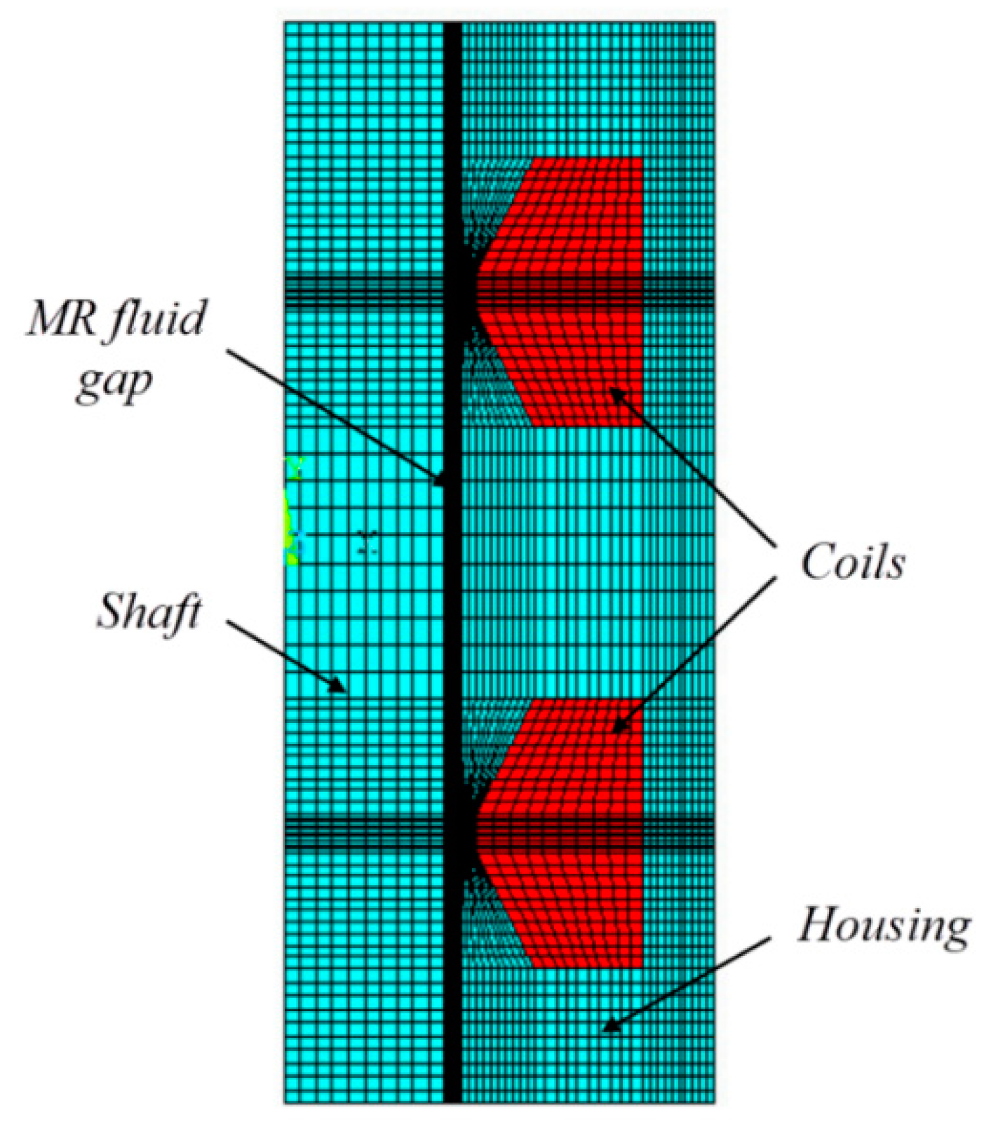
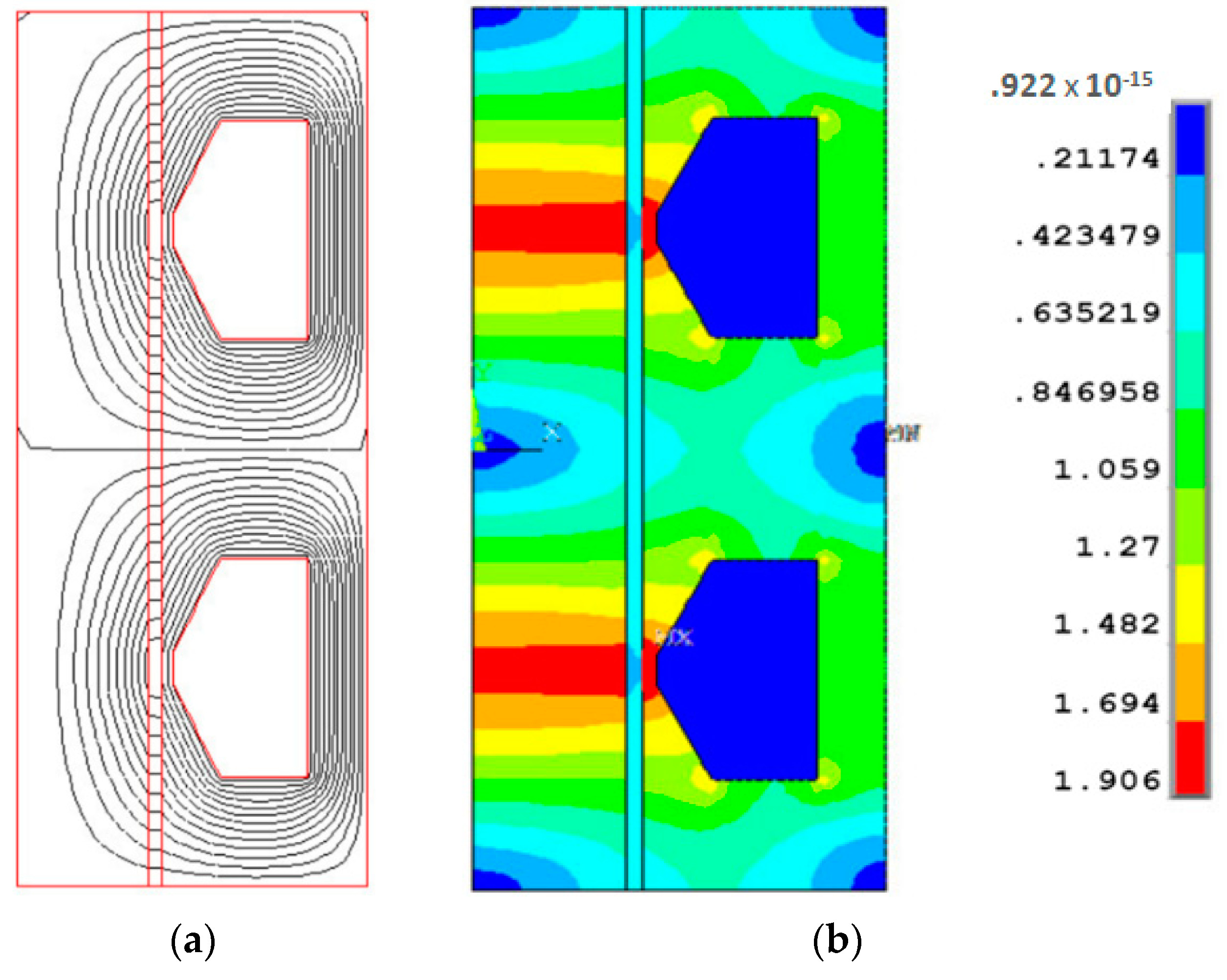
4.2. Optimal Design of the MR Damping Part

In order to improve the performance of the MR damping part during the operating process of washing machines, the maximum damping force (the damping force when a magnetic field is applied) determined by Equation (11) reaches to a required value at low resonance frequency whereas the zero-field friction force in Equation (12) is minimized at high excitation frequencies. Therefore, the dynamic model of washing machines should be first analyzed. The 2D mechanical modeling of the washing machine Samsung WF8690NGW is shown in Figure 7.
The vibration equation of the washing machine shown in Figure 7 can be represented [10] as
m u ¨ + c u ˙ [ sin 2 ( φ + β 2 ) + sin 2 ( φ β 1 ) ] + k u [ sin 2 ( φ + α 1 ) + sin 2 ( φ α 2 ) ] = F u ( t )
where k is the spring stiffness, c is the damping coefficient, m is the total mass of the tub assembly, φ is the angle from the x axis of an arbitrary direction u of the vibration analysis, and ∆u is the displacement of the center of the tube in the u direction. The exciting force Fu due to an imbalanced mass in the u direction is defined by
F u = F u 0 cos ( ω t ) = m u ω 2 R u cos ( ω t )
where Fu0 is the magnitude of the exciting force and Ru and mu are the radius and mass from the rotary axis of the imbalanced mass, respectively. From Equation (15), the damped frequency ωd, natural frequency ωn, and damping ratio ξ of the suspended tub assembly are given by
ω d = ω n 1 ξ 2
ω n = k [ sin 2 ( φ + α 1 ) + sin 2 ( φ α 2 ) ] m
ξ = c [ sin 2 ( φ + β 2 ) + sin 2 ( φ β 1 ) ] 2 m k [ sin 2 ( φ + α 1 ) + sin 2 ( φ α 2 ) ]
The resonance in all directions of vibration should be attenuated as much as possible. For this, by designing α1 + α2 = 90° and β1 + β2 = 90°, Equations (15), (18) and (19) can be simplified to be independent of the angle φ as follows
m u ¨ + c u ˙ + k u = F u ( t )
ω n = k m ;   ξ = c 2 m k
In this case, the force transmissibility Tf from the tub assembly to the cabinet is derived by
T f = 1 + ( 2 ξ r ω ) 2 ( 1 r ω 2 ) 2 + ( 2 ξ r ω ) 2
where rω = ω/ωn is the frequency ratio. Figure 8 presents the relation between the force transmissibility and the excitation frequency under different damping ratios. From the figure, it is observed that the resonant peaks are nearly eliminated as the damping ratio ξ reaches to 0.7. Thus, it is not necessary to get the greater value of ξ.
According to [10], the expected damping force for the MR damping part Fr can be determined by
F r = k X π ξ r ω 2
where the tub vibration amplitude X is given by
X = F u 0 k 1 ( 1 r ω 2 ) 2 + ( 2 ξ r ω ) 2 = m u r ω 2 R u m 1 ( 1 r ω 2 ) 2 + ( 2 ξ r ω ) 2
In this study, it is assumed that the total mass of the tub assembly m is 40 kg, the spring stiffness k is 10 kN/m, and the imbalanced mass mu is 7 kg placed at the radius from the rotary axis Ru 0.125 m. For the desired damping ratio ξ = 0.7 at the resonance frequency ratio r ω = 1 ξ 2 , the expected damping force Fr in Equation (23) is calculated as 78.7 N. Consequently, the damping force object for the MR damping part is established by 80 N.
In the design optimization of the MR damping part, the design variables are the radius of shaft rs, the height of coil hc, the width of coil wc, the dimensions of chamfer hch and wch, the length of pole lp, and the thickness of housing to. Considering the installation space in the washing machine, the available length of the MR fluid gap L is approximately 60 mm. For simple structure, the outer radius of the MR damping part is set to equal to that of the EH part. The final restriction comes from, similar to the EH part, the ability of machining and assembling, for which the thickness of the housing to are set to be greater than 2 mm. The design optimization problem of the MR damping part, in summary, can be expressed: Determine the optimal geometry of the proposed MR damping part that minimize the off-state friction force F0, subjected to the length of the MR fluid gap L is smaller than 60 mm and the maximum damping force Fd is higher than 80 N (the expected damping force).
Figure 9 shows the finite element model of the MR damping part created on the ANSYS software. First, the magnetic circuits of the MR damping part are solved based on FEA to calculate the magnetic density B. The postyield viscosity η and yield stress τy are then estimated using Equation (14). Finally, these parameters are substituted into Equations (11) and (12) to obtain the damping force and zero-field friction force, respectively.
The optimal solution of the proposed MR damping part is characterized in Table 3. The thickness of the MR fluid gap should not be too large considering the MR fluid amount and the O-ring size. Also, the thickness of the thin wall should be as small as possible for a quick magnetic saturation. In this work, both are set as 0.8 mm taking the manufacturing cost into consideration. Figure 10a,b represents the magnetic flux distribution and flux density of the optimized MR damping part, respectively. As shown in Figure 10a, by optimizing design, a greater damping force is generated since the MR fluid could be active throughout the gap length. From Figure 10b, it is also seen that the magnetic flux density in the thin wall, the inner housing, and the shaft are almost saturated. This implies that the damping force reaches to saturation, too.

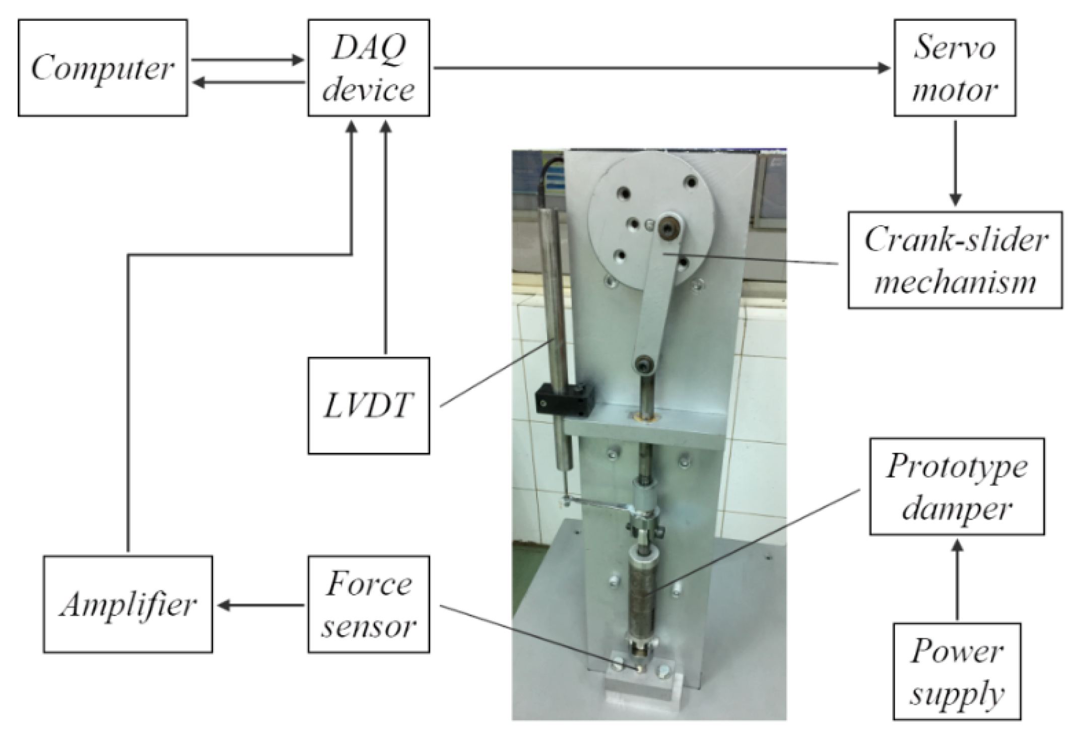
5. Experimental Validation

Figure 11 and Figure 12 show the prototype of the optimized self-powered MR damper and experimental setup, respectively, for verifying the optimal design results and evaluating the performance of the damper. In this test system, a servo motor (MSMD022S1T, Panasonic) with gearbox of ratio 15:1 is employed to provide a constant rotary speed for the crank shaft. The rotary motion of the motor is converted to the linear motion of the damper shaft by a crank-slider mechanism. The damping force is measured by a bidirectional force sensor produced by Forsentek Co., Limited, Shenzhen, China (FFG-200N, maximum measured force: 200 N) while the instantaneous velocity and displacement are measured by a linear variable differential transformer (LVDT) produced by RPD Electrosense (ACT1000A, measurement range: +/−25 mm). In order compare the self-power MR damper with the MR damper using external power, a programmable power supply (PPW-8011, TWINTEX) is employed to supply power to the coils of the damping part. The power supply is controlled by the computer through the DAQ (myRIO 1900, National Instruments) to supply desired currents. It is noted that signals from the force sensor and LVDT are also transferred to the computer through the DAQ.

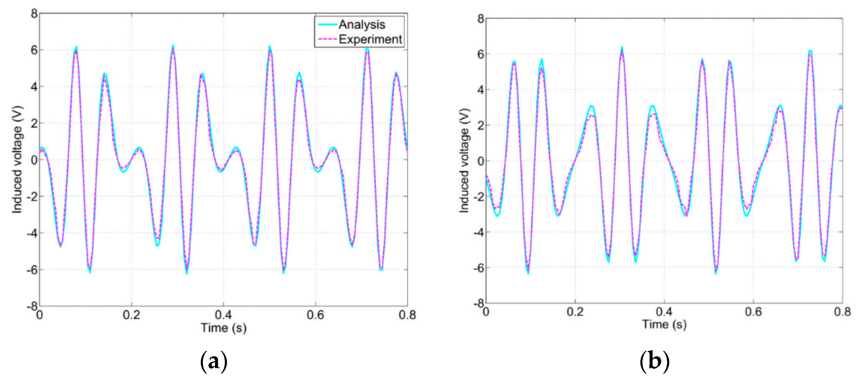
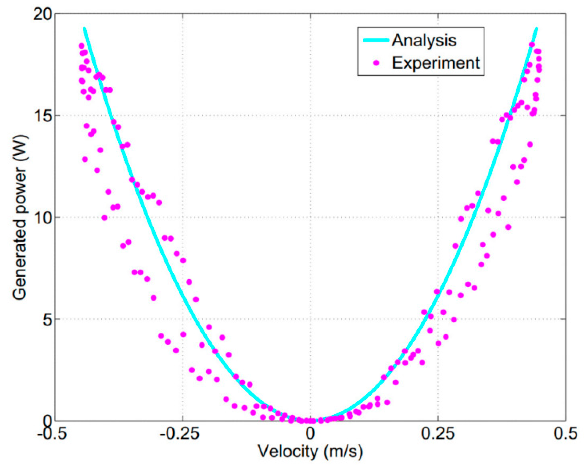
5.1. Performance of the Energy-Harvesting Part

From Equations (6)–(9), it is shown that the induced voltages of two contiguous coils express the properties of the EH part. To validate the efficiency of the power generation, a harmonic excitation of 2.4 Hz frequency and 30 mm amplitude is applied to the prototype self-powered MR damper. This is the frequency when the first resonance often appears in most commercial washing machines. Figure 13 presents the comparisons between the theoretical modeling and experimental measurement of the induced voltages of coils 1 and 2. As shown in the figure, it is observed that the experimentally measured induced voltages are slightly lower than those obtained from theoretical analysis. This mostly results from the measurement noises and magnetic flux leakage. The average value of the produced voltages of coil 1 and coil 2 are about 93.7% and 93.8% of the simulated value, respectively. Thus, the experimental data matches well with the simulation results. Moreover, numbers of peaks are found in one excitation period of the generated voltages, due to the effect of the induced voltage frequency multiplication [17]. This would increase the overall harvested power and thus is very advantageous to the EH part.
Figure 14 shows the comparison between the numerical analysis and experimental results of the generated power with respect to the velocity excitation. As shown in the figure, the produced power almost exhibits a parabolic relation to the velocity excitation. The average error between the theoretical and experimental generated powers is about 8.4%. As a result, the experimental data of the generated power matches well with the simulation results.

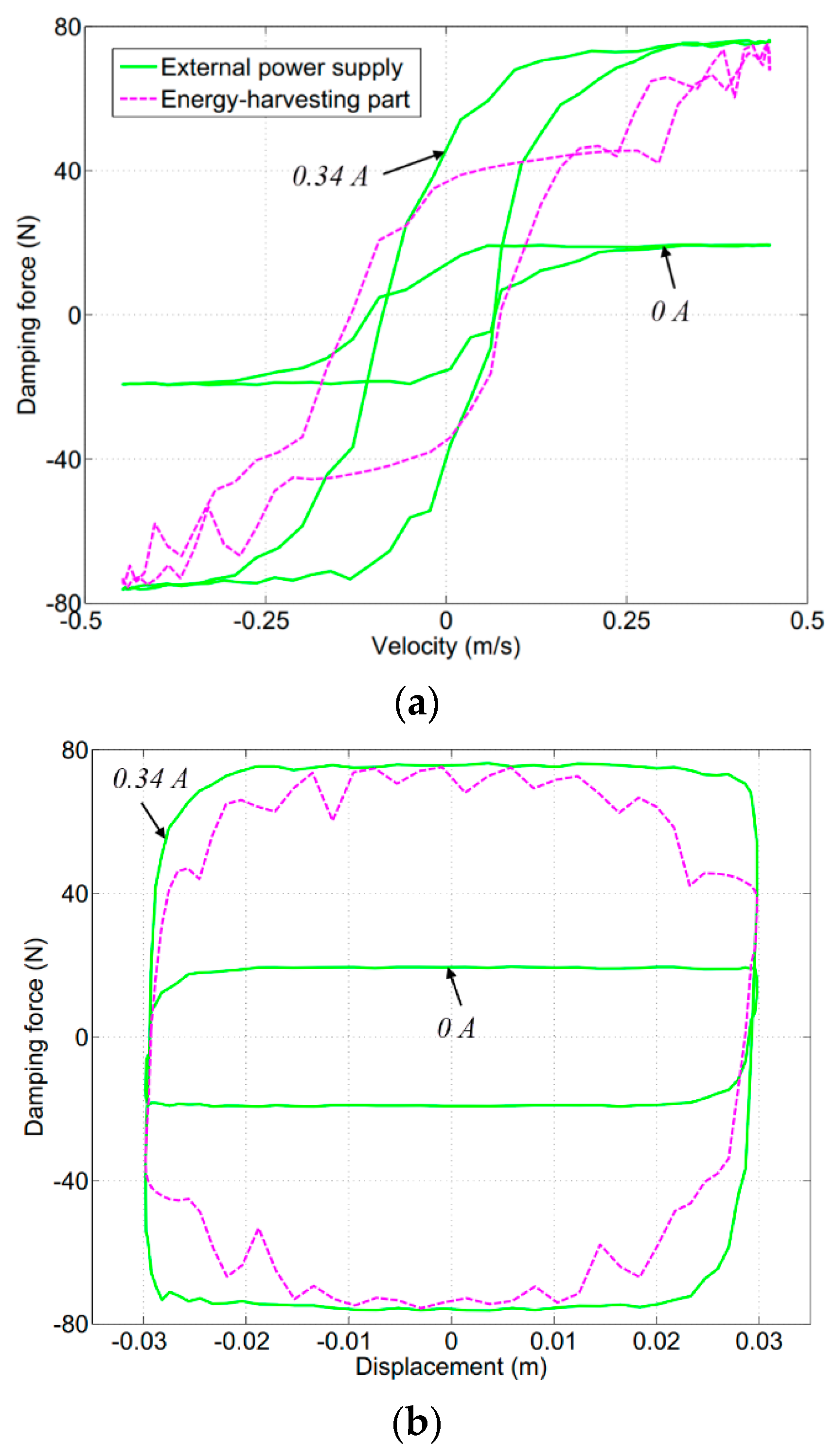
5.2. Damping Force under Constant Magnetic Field

The damping performance is tested when the EH part is open and different constant currents are applied to the exciting coils of the MR damping part by an external power supply. Figure 15 shows the force-velocity and force-displacement curves under the often-resonant frequency of 2.4 Hz, amplitude of 30 mm, and different currents of 0, 0.2, 0.34 (the maximum value in Table 3 obtained from theoretical modeling), and 0.4 A. It is noted that the damping part of the self-powered damper in this research are similar to that of the MR damper in [12]; therefore, the experimental results in Figure 15 are almost the same as those in [12]. From the figure, it can be realized that the damping force significantly depends on the external magnetic field. When there is no current applied to the exciting coils (I = 0), the force-displacement curve is almost elliptic and the force-velocity relation is approximately linear, which indicate that the behavior of the MR damper is nearly similar to that of a pure viscous damper. However, the forces in this case are not concentrated in the vicinity of zero due to the presence of the frictional forces between the shaft and the O-rings. There is a slight difference between the zero-field force obtained from the experiment and that obtained from the theoretical modeling. The average value of the zero-field force at the steady position (the position relatively far from the stroke ends) is 19.5 N, which is around 106% of the modeling value (18.4 N). This results from the inaccurate estimation of the friction force of the O-rings. It is believed that the accuracy would be improved with further tests on the O-rings.
When the magnetic field intensity increases (I > 0), the area of the force-displacement loop increases considerably, meaning that additional damping forces are produced. As shown in the figure, when the current of 0.34 A is applied to the coils, the maximum damping force increases from 19.5 to 76.2 N, which is around 95% of the simulated one (80.2 N). The difference mainly comes from the loss of magnetic field to the ambient and at the contact between the magnetic parts. However, when the current is increased to 0.4 A, no more significant change in force is found. Thus, it is proved that the damping force almost reaches to saturation at 0.34 A of the applied current.
Moreover, as shown by the force–velocity responses in Figure 15a, the self-powered MR damper experiences two particular rheological regions: the preyield (rectangular mark) and postyield (the rest of the loop) regions. The preyield region exposes a strong hysteretic phenomenon while the postyield one almost exhibits a linear relationship. It is observed that in the preyield region, a sudden decrease/increase in value of damping forces corresponding to small velocities appears. This roll-off effect has been investigated in many researches.

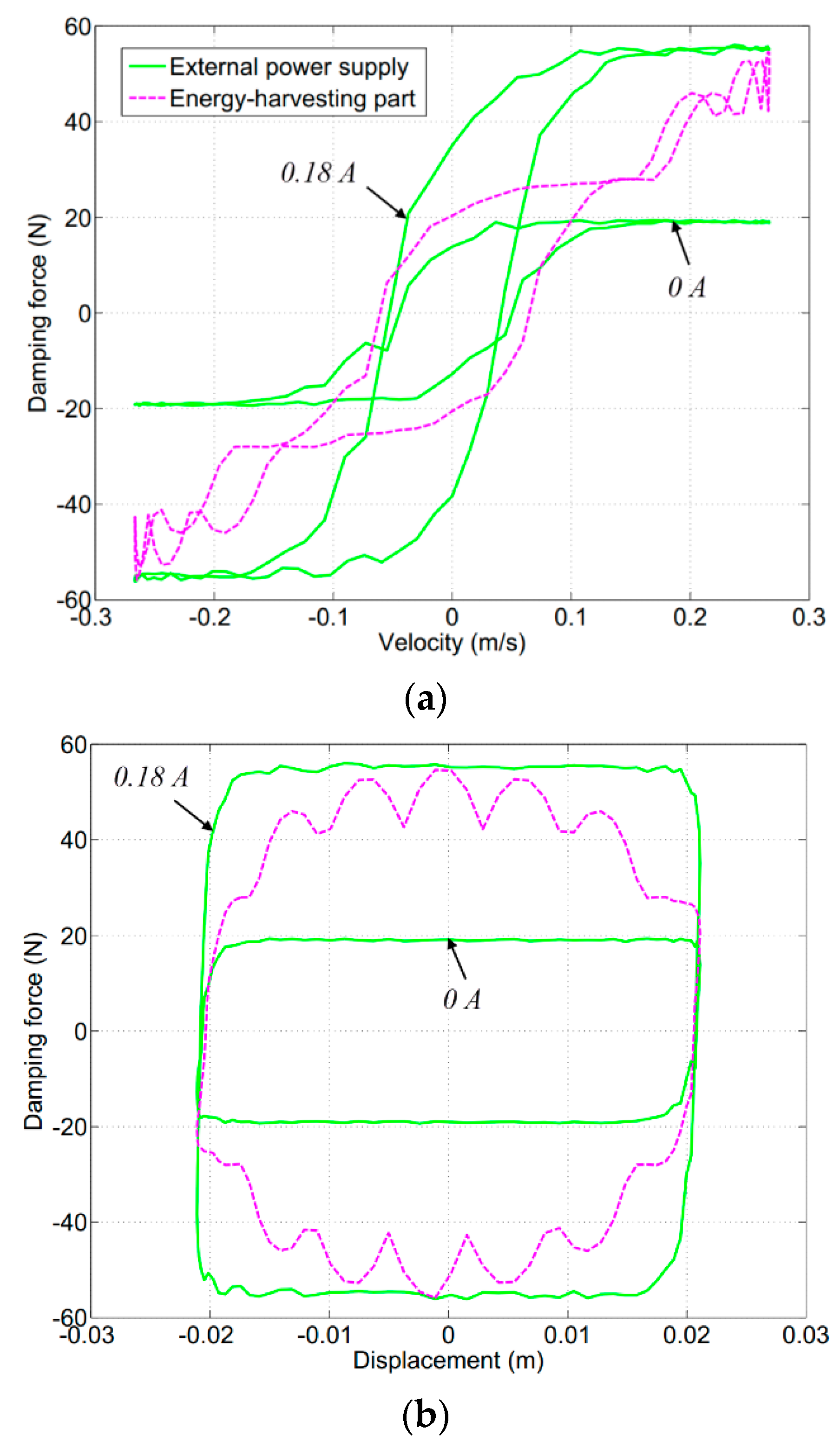
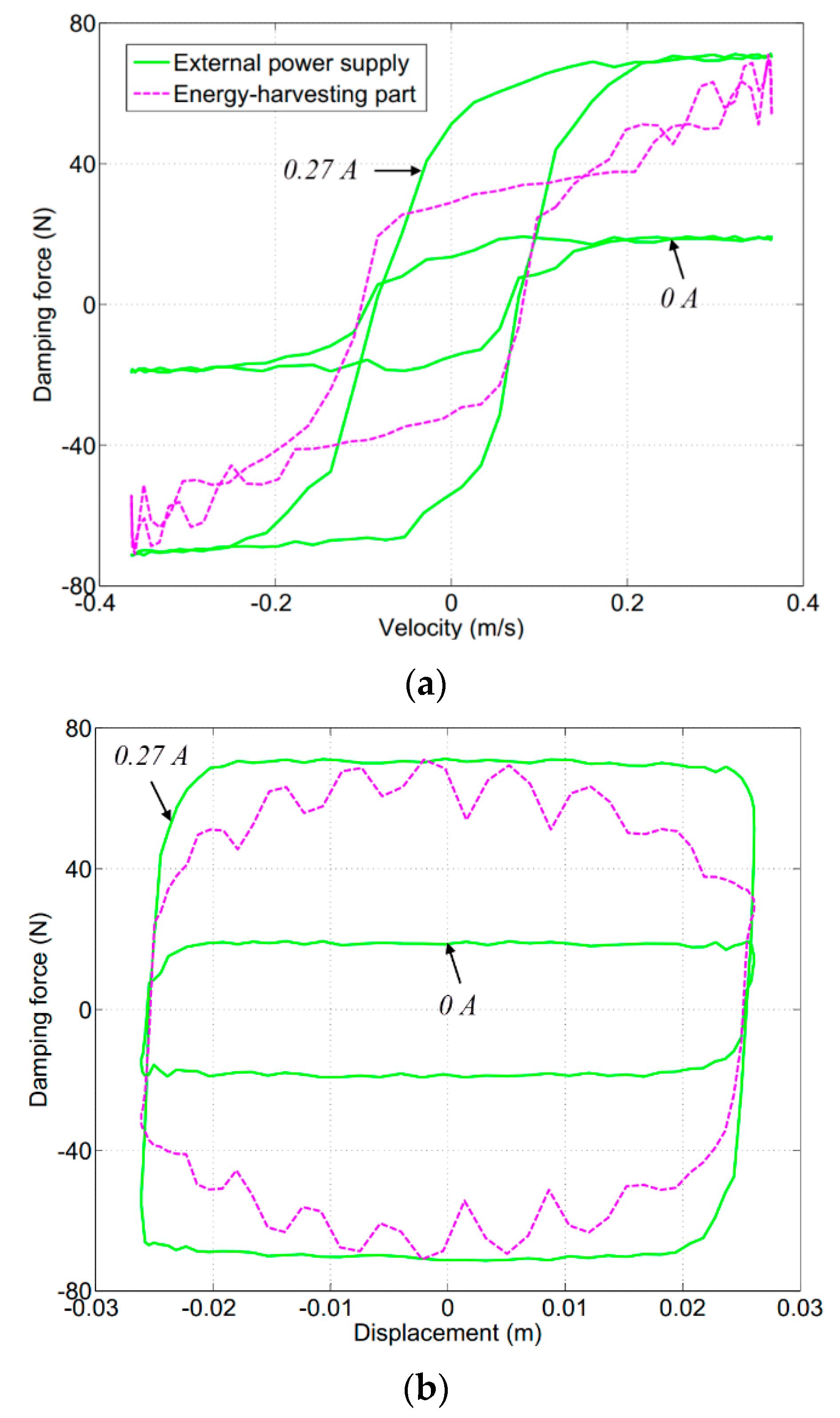
5.3. Self-Adaptability of the Damping Force

Experiments are implemented to verify the self-adaptability of the damping force when the EH part is close. Figure 16 shows the comparison between the damping force with the EH part and that under constant currents when an excitation of 2.4 Hz frequency and 30 mm amplitude is applied to the prototype self-powered MR damper. As shown in the figure, the damping force with the EH part varies between the levels of 0 and 0.34 A constant currents. The maximum damping force with the EH part is 75.1 N, which is almost the same as that under the 0.34 A constant current (76.2 N) since the difference is only about 1.4%. It is also observed from Figure 16a that the force-velocity loop of the MR damper powered by the EH part experiences a hysteresis in the preyield region, but not a linear relationship in the postyield region. The explanation can be easily found on the continuous variation of the voltages generated by the EH part. Besides, in Figure 16b, it is realized that the area of the force-displacement loop with the EH part is smaller than that under the 0.34 A constant current. The generated work of the MR damper in case of the 0.34 A constant current is about 8.7 J, while the MR damper with the EH part handles only about 7.4 J. In other words, the MR damper supplied by the external power source with the constant current dissipates more energy than that by the EH part.
The same conclusions could be drawn from Figure 17 and Figure 18 when the prototype damper is tested under a 2 Hz frequency and a 21 mm amplitude and a 2.2 Hz frequency and a 26 mm amplitude, respectively. These are also the excitations that often appear when washing machines are entering the resonance region. Although the maximum damping forces produced by the MR damper with the EH part decrease due to the reduction of the excitation velocities, they are still high enough to attenuate the vibration of washing machines that has not reached to resonance peak yet. Consequently, the feasibility of the proposed self-powered shear-mode MR damper for washing machines has been demonstrated.

6. Conclusions

This paper focused on the design and evaluation of a self-powered shear-mode MR damper for washing machines to dissipate the vibratory energy due to an imbalanced laundry mass occurring in the washing drum. In order to improve the performance of the proposed damper, an optimization procedure employing the ANSYS FEA with golden section algorithm was performed considering expected damping force, installation space, size, and production cost. Based on the optimal solutions, a prototype of the proposed self-powered MR damper was designed and manufactured.
Theoretical analyses and experimental studies on the EH part were performed. The induced voltage of each coil was about 94% of the predicted value and the appearance of the frequency multiplication effect would be beneficial to the overall harvested energy. The generated power almost represented a quadratic function of the velocity with the average error of about 8.4%. Accordingly, a good correlation between the modeling based on FEA and experimental results of the EH part was achieved.
For the damping ability under constant magnetic fields, the performance of the MR damping part was tested when the EH part was open. The results showed that the proposed MR damper could provide and control effectively the damping force. The damping force almost reached to saturation at 0.34 A current, which agreed well with the theoretical simulation. The zero-field friction force was a little greater than the modeling value. It was advised that further experiments on the O-rings should be implemented to better evaluate their friction forces.
For the self-adaptability of the damping force, the MR damper with the closed EH part was investigated and discussed via both simulation and experiment. The experimental results indicated that the proposed self-powered MR damper could generate the same maximum damping force as under corresponding constant currents but dissipated less energy. This would reduce the power consumption and heat emission as compared with the conventional MR dampers.
With the EH part integrated into the MR damper, the system could be powered by itself from wasted mechanical energy. The complication and cost of the system are considerably reduced since the proposed damper could be self-adaptable to external excitations. However, comparing with MR damper working on external power, damping force obtained from the self-powered damper has more fluctuation. As the second phase of this research, further efforts will concentrate on experimentally studying the friction force of the O-rings and validating the proposed self-powered MR damper in prototype washing machines.

Author Contributions

Q.-D.B. is working on this research topic. He is in charge of configuration design, detailed design, formal analysis, validation, prototype manufacturing and write the first draft of the manuscript; Q.H.N. is the corresponding author of this research work. He is in charge of conceptualization, methodology and final editing of the manuscript; T.T.N. is in charge of program coding and data curation in this research; D.-D.M. is responsible for planning and collecting resources, visualization, investigation and supervision of prototype manufacturing in this research; All authors have read and agreed to the published version of the manuscript.

Funding

This work was supported by the Vietnam National Foundation for Science and Technology Development (NAFOSTED) under grant no. 107.01-2018.335.

Conflicts of Interest

The authors declare no conflict of interest.

Nomenclatures

AcSectional area of the inducing coil
AgmCylindrical surface area of the air gap
AmSectional area of the magnet
ArProjected area of the seal
BApplied magnetic density
BremMagnet remanent flux density
cDamping coefficient
dwDiameter of the copper wire
EInduced voltage in the inducing coil
EiInduced voltages in the i active coil
EHEnergy-harvesting
F0Zero-field friction force
FdDamping force
ForCoulomb friction force between the shaft and the O-ring
FrRequired damping force for the MR damping part
FuExciting force due to an unbalanced mass in the u direction
Fu0Magnitude of the exciting force
fcFriction per unit length caused by the compression of the O-ring
fhFriction force caused by the fluid pressure on a unit projected area of the O-ring
HcoeMagnetic coercivity of the magnet
hcHeight of the exciting coil
hch, wchChamfer dimensions of the exciting coil
hcmHeight of the inducing coil
IApplied current
kStiffness of each spring
LLength of the MR fluid gap
LeEffective length of the active MR fluid in the gap
LrLength of the seal rubbing surface
LsLength of the shaft end
lmLength of the magnet
lpLength of the pole of the MR damping part
MRFMagnetorheological fluid
mMass of the suspended tub assembly
muUnbalanced mass
NNumber of winding turns of each inducing coil
PPower of four active coils
P1, P2Powers of coil 1 and coil 2
pcPitch of the coil slot of the EH part
pmPitch of the pole pair of the EH part
ROuter radius of the self-powered MR damper
RcResistance of each inducing coil
RsRadius of the shaft
RuRadius from the rotation axis of the unbalanced mass
riInner radius of the magnet
roOuter radius of the magnet
rsRadius of the shaft
rωFrequency ratio
TfForce transmissibility from the tub assembly to the cabinet
tTime
tgThickness of the MR fluid gap
tgmThickness of the air gap
toThickness of the outer housing of the MR damping part
tomThickness of the housing of the EH part
twThickness of the thin wall of the MR damping part
twmThickness of the thin wall of the EH part
vVelocity of the shaft
wcWidth of the exciting coil
wcmWidth of the inducing coil
XAmplitude of the tub vibration
xDisplacement of the shaft
YMR fluid rheological property such as postyield viscosity or yield stress
α1, α2Angle between the spring and the y-axis
αSYSaturation moment of the Y property
β1, β2Angle between the damper and the y-axis
uDisplacement of the center of the tube assembly in the u direction
ηPostyield viscosity of the active MR fluid in the gap
λEfficiency of the magnetic flux considering leakage effect
µ0Relative magnetic permeability
ξDamping ratio
τyField-dependent yield stress of the active MR fluid in the gap
ΦgMagnetic flux of the air gap between the magnets and the stator core
φAngle of the u direction
φ0Initial phase angle of the inducing coil
ωdDamped frequency
ωnNatural frequency

References

  1. Stone, E.J.; Cebon, D. Control of semi-active anti-roll systems on heavy vehicles. Veh. Syst. Dyn. 2010, 48, 1215–1243. [Google Scholar] [CrossRef]
  2. Erkus, B.; Johnson, E.A. Dissipativity analysis of the base isolated benchmark structure with magnetorheological fluid dampers. Smart Mater. Struct. 2011, 20, 105001. [Google Scholar] [CrossRef]
  3. Makowski, M.; Knap, L. Investigation of an off-road vehicle equipped with magnetorheological dampers. Adv. Mech. Eng. 2018, 10, 1–11. [Google Scholar] [CrossRef]
  4. Seong, M.S.; Choi, S.B.; Kim, C.H. Design and Performance Evaluation of MR Damper for Integrated Isolation Mount. J. Intell. Mater. Syst. Struct. 2011, 22, 1729–1738. [Google Scholar] [CrossRef]
  5. Papadopoulos, E.; Papadimitriou, I. Modeling, design and control of a portable washing machine during the spinning cycle. In Proceedings of the 2001 IEEE/ASME International Conference on Advanced Intelligent Mechatronics, Como, Italy, 8–12 July 2001; pp. 899–904. [Google Scholar]
  6. Koizumi, T.; Tsujiuchi, N.; Matsumoto, S.; Hirasawa, Y. Noise prediction of a washing machine considering panel vibration. In Proceedings of the IMAC-XXIV Conference and Exposition on Structural Dynamics, St. Louis, MO, USA, 30 January–2 February 2006. [Google Scholar]
  7. Lim, H.T.; Jeong, W.B.; Kim, K.J. Dynamic modeling and analysis of drum-type washing machine. Int. J. Precis. Eng. Manuf. 2010, 11, 407–417. [Google Scholar] [CrossRef]
  8. Carlson, J.D. Low-cost MR fluid sponge devices. J. Intell. Mater. Syst. Struct. 1999, 10, 589–594. [Google Scholar] [CrossRef]
  9. Aydar, G.; Evrensel, C.A.; Gordaninejad, F.; Fuchs, A. A low force magneto-rheological (MR) fluid damper: Design, fabrication and characterization. J. Intell. Mater. Syst. Struct. 2007, 18, 1155–1160. [Google Scholar] [CrossRef]
  10. Nguyen, Q.H.; Nguyen, N.D.; Choi, S.B. Optimal design and performance evaluation of a flow-mode MR damper for front-loaded washing machines. Asia Pac. J. Comput. Eng. 2014, 1, 3. [Google Scholar] [CrossRef] [Green Version]
  11. Nguyen, Q.H.; Choi, S.B.; Woo, J.K. Optimal design of magnetorheological fluid-based dampers for front-loaded washing machines. Proc. Inst. Mech. Eng. C-J. Mec. Eng. Sci. 2014, 228, 294–306. [Google Scholar] [CrossRef]
  12. Bui, D.Q.; Hoang, V.L.; Le, H.D.; Nguyen, Q.H. Design and evaluation of a shear-mode MR damper for suspension system of front-loading washing machines. In Proceedings of the International Conference on Advances in Computational Mechanics, Phu Quoc Island, Vietnam, 2–4 August 2017; pp. 1061–1072. [Google Scholar]
  13. Ulasyar, A.; Lazoglu, I. Design and analysis of a new magneto rheological damper for washing machine. J. Mech. Sci. Technol. 2018, 32, 1549–1561. [Google Scholar] [CrossRef]
  14. Cho, S.W.; Jung, H.J.; Lee, I.W. Smart passive system based on magnetorheological damper. Smart Mater. Struct. 2005, 14, 707–714. [Google Scholar] [CrossRef]
  15. Choi, K.M.; Jung, H.J.; Lee, H.J.; Cho, S.W. Feasibility study of an MR damper-based smart passive control system employing an electromagnetic induction device. Smart Mater. Struct. 2007, 16, 2323–2329. [Google Scholar] [CrossRef]
  16. Kim, I.H.; Jung, H.J.; Koo, J.H. Experimental evaluation of a self-powered smart damping system in reducing vibrations of a full-scale stay cable. Smart Mater. Struct. 2010, 19, 115027. [Google Scholar] [CrossRef]
  17. Chen, C.; Liao, W.H. A self-sensing magnetorheological damper with power generation. Smart Mater. Struct. 2012, 21, 025014. [Google Scholar] [CrossRef]
  18. Hu, G.; Lu, Y.; Sun, S.; Li, W. Performance analysis of a magnetorheological damper with energy harvesting ability. Shock Vib. 2016, 1–10. [Google Scholar] [CrossRef] [Green Version]
  19. Xinchun, G.; Yonghu, H.; Yi, R.; Hui, L.; Jinping, O. A novel self-powered MR damper: Theoretical and experimental analysis. Smart Mater. Struct. 2015, 24, 105033. [Google Scholar] [CrossRef]
  20. Ebrahimi, B.; Khamesee, M.B.; Golnaraghi, M.F. Feasibility study of an electromagnetic shock absorber with position sensing capability. In Proceedings of the 34th Annual Conference of IEEE Industrial Electronics, Orlando, FL, USA, 10–13 November 2008; pp. 2988–2991. [Google Scholar]
  21. Nguyen, Q.H.; Han, Y.M.; Choi, S.B.; Wereley, N.M. Geometry optimization of MR valves constrained in a specific volume using the finite element method. Smart Mater. Struct. 2007, 16, 2242–2252. [Google Scholar] [CrossRef]
  22. Nguyen, Q.H.; Choi, S.B.; Wereley, N.M. Optimal design of magneto-rheological valves via a finite element method considering control energy and a time constant. Smart Mater. Struct. 2008, 17, 1–12. [Google Scholar] [CrossRef]
  23. Cleveland, O.H. Parker O-Ring handbook. Parker Hannifin Corporation: Cleveland, OH, USA, 2018. [Google Scholar]
  24. Zubieta, M.; Eceolaza, S.; Elejabarrieta, M.J.; Ali, M.M.B. Magnetorheological fluids: Characterization and modeling of magnetization. Smart Mater. Struct. 2009, 18, 095019. [Google Scholar] [CrossRef]
Figure 1. Force transmissibility of washing machines using different vibration control systems.
Applsci 10 04099 g001
Figure 2. Schematic of the proposed self-powered shear-mode magnetorheological (MR) damper.
Applsci 10 04099 g002
Figure 3. Schematic of the energy-harvesting part.
Applsci 10 04099 g003
Figure 4. Finite element model of the energy-harvesting part.
Applsci 10 04099 g004
Figure 5. Finite element analysis of the optimized energy-harvesting part: (a) magnetic flux lines and (b) magnetic flux density.
Applsci 10 04099 g005
Figure 6. Schematic diagram of the shear-mode MR damping part.
Applsci 10 04099 g006
Figure 7. A 2D mechanical modeling of the washing machine.
Applsci 10 04099 g007
Figure 8. Relation between the force transmissibility and the excitation frequency under a damping ratio of 0.1–0.7 with an increment of 0.1.
Applsci 10 04099 g008
Figure 9. Finite element model of the MR damping part.
Applsci 10 04099 g009
Figure 10. Finite element analysis of the optimized MR damping part: (a) magnetic flux line and (b) magnetic flux density.
Applsci 10 04099 g010
Figure 11. Prototype of the optimized self-powered MR damper (a) and its disintegrated components (b).
Applsci 10 04099 g011
Figure 12. Experimental setup for testing the performance of the prototype self-powered MR damper.
Applsci 10 04099 g012
Figure 13. Comparisons between the experimental and modeling results of the induced voltages of coils under 2.4 Hz frequency and 30 mm amplitude: (a) coil 1 and (b) coil 2.
Applsci 10 04099 g013
Figure 14. Comparison between the simulation and experimental results of the generated power under 2.4 Hz frequency and 30 mm amplitude.
Applsci 10 04099 g014
Figure 15. Experimental responses under a frequency of 2.4 Hz, an amplitude of 30 mm, and different currents of 0, 0.2, 0.34 (continuous lines from inside to outside), and 0.4 A (dash line): (a) force vs. velocity and (b) force vs. displacement.
Applsci 10 04099 g015
Figure 16. Experimental results of the MR damper with the energy-harvesting (EH) part and under constant external currents in the case when the excitation is 2.4 Hz frequency and 30 mm amplitude: (a) force vs. velocity and (b) force vs. displacement.
Applsci 10 04099 g016
Figure 17. Experimental results of the MR damper with the EH part and under constant external currents in the case when the excitation is 2 Hz frequency and 21 mm amplitude: (a) force vs. velocity and (b) force vs. displacement.
Applsci 10 04099 g017
Figure 18. Experimental results of the MR damper with the EH part and under constant external currents in the case when the excitation is 2.2 Hz frequency and 26 mm amplitude: (a) force vs. velocity and (b) force vs. displacement.
Applsci 10 04099 g018
Table 1. Optimal parameters of the energy-harvesting part.
Parameter (mm)ValueParameter (mm)Value
Coil height hcm4.4Air gap thickness tgm0.8
Coil width wcm4.56Thin wall thickness twm0.8
Coil pitch pc6.74Housing thickness tom2
Magnet length lm7Outer radius R22
Pole pair pitch pm13.48Generated power P (W)19.3
Table 2. Rheological properties of the magnetorheological (MR) fluid 132-DG.
Parameters
η0 = 0.1 Pa·sτy0 = 15 Paα = 4.5 T−1
η = 3.8 Pa·sτy∞ = 40,000 PaαSτy = 2.9 T−1
Table 3. Optimal parameters of the MR damping part.
Parameter (mm)ValueParameter (mm)Value
Coil height hc8.57Thin wall thickness tw0.8
Coil width wc13.81Housing thickness to3.58
Coil height chamfer hch3.05Shaft radius rs8.25
Coil width chamfer wch5.9Outer radius R22
Pole length lp6.88Max. current intensity I (A)0.34
MR fluid gap length L55.13Max. damping force Fd (N)80.2
MR fluid gap thickness tg0.8Zero-field friction force Fo (N)18.4

