Article

A Form-Free and High-Precision Metrological Method for the Twist of Aeroengine Blade

1
Hebei Key Laboratory of Safety Monitoring of Mining Equipment, College of Mechanical and Electrical Engineering, North China Institute of Science and Technology, Sanhe 065201, China
2
Beijing Engineering Research Center of Precision Measurement Technology and Instruments, College of Mechanical Engineering and Applied Electronics Technology, Beijing University of Technology, Beijing 100124, China
*
Author to whom correspondence should be addressed.
Appl. Sci. 2020, 10(12), 4130; https://doi.org/10.3390/app10124130
Submission received: 16 May 2020 / Revised: 9 June 2020 / Accepted: 13 June 2020 / Published: 16 June 2020
(This article belongs to the Special Issue Manufacturing Metrology)

Abstract

:
In order to solve the problems in the accuracy and adaptability of the existing methods for blade twist measurement, a high-precision and form-free metrological method of blade twist based on the parameter evaluation of twist angular position and twist angle is proposed in the study, and the theoretical model, the measurement principle and the key technologies of the method are discussed in detail. Three key issues of the twist metrology of a blade are solved based on technologies of calibration, a priori planning and geometric analysis: aeroengine axis matching, high-precision coordinate acquisition of the leading edge and the trailing edge, and extraction of twist angular position of the profile. The measurement path planning, sampling strategy optimization and high-precision coordinate collection are executed automatically without theoretical model data of the measured blade, thus the form-free and high-precision metrology of the blade twist is achieved. The research results show that the metrological method of blade twist presented in this study is effective, and that its measurement uncertainty is less than 0.01°. This method is form-free, efficient and accurate, and can solve the problems of high-precision measurement and evaluation for the twist of aeroengine blade primely.

Graphical Abstract

1. Introduction

In order to maintain the optimal distribution of airflow in the cascade passage, avoid the separation of airflow and reduce the blade loss, the aeroengine blade must be twisted and stacked by profiles along the airfoil height direction [1]. The twist of the blade plays an important role in optimizing and improving the aerodynamic performance of an aeroengine, and its measurement and evaluation are of great significance. Gao et al. [2,3] studied the influence law of blade machining error on the aerodynamic performance of a compressor and pointed out that the torsional error of the blade is an important factor affecting the loss of the blade profile. Zhang et al. [4] analyzed the influence of blade profile deviation on turbine performance by numerical simulation, and concluded that the deviation of blade profile changes the field structure and the acceleration law of the airflow in the turbine passage, thus affecting the aerodynamic performance of the turbine. Cheng et al. [5] researched the effects of six typical blade parameters on compressor performance and drew a conclusion that blade torsion error has an important influence on overall pressure ratio, efficiency, flow rate, etc.
At present, the measuring technologies of two-dimensional profile parameters such as the maximum thickness of the profile and the radius of the leading and trailing edges are relatively perfect, and the extraction algorithms of parameters are more mature [6,7,8]. However, the measurement and evaluation of blade twist, which characterizes the torsion law of a blade in three-dimensional space, remains a challenge. Difficulties in the measurement of the blade twist are mainly manifested in the following aspects: (1) The twist is a three-dimensional geometric parameter of the blade. The measuring model is complex and the characterization and evaluation are difficult. (2) The parameter of twist angular position is defined by the angle between the profile chord and the axial line of engine. It is another difficult problem to locate the axial line of the engine fast and accurately, and to establish the measurement datum. (3) It is hard to achieve a high-precision measurement of blade twist. Many error factors such as the coordinate acquisition accuracy of the leading and trailing edges and the extraction algorithms of the profile chord line have a great influence on the accuracy of blade twist measurement.
At present, some progress has been made in blade twist measurement, and some mature commercial products in the market can be found to meet the basic requirements of blade twist measurement, such as CMM (Coordinate Measuring Machine) of the Global Series from HEAXGON and CORE DS from WENZEL. The existing measuring methods of blade twist mainly involve two categories: the contact measurement method of CMM and the non-contact optical measurement method [9].
Contact measurement technology is the first applied blade twist measurement technology. Su et al. [10] proposed a two-point measurement method for blade torsional deformation. This method can be used to estimate the rough deformation state of the blade, but measurements with just two points may lose important information and cannot evaluate the blade twist angle with high accuracy. Shi et al. [11] studied a contact measuring method for blades based on CMM and proposed a variable-speed scanning method based on curvature recognition. The method improves the accuracy of measurement by optimizing the measurement path, but has a poor efficiency. Bu et al. [12] analyzed the influence of CMM sampling points on the measurement accuracy of characteristic parameters for turbine blades, and improved the measurement accuracy of parameters such as twist angle by optimizing the sampling strategy. There are disadvantages and constraints in the measurement of blade twist based on contact measurement technology: (1) The theoretical model of the measured blade is necessary for path planning and result analysis, which limits measurement adaptability greatly. (2) The measurement efficiency is low, and the high-speed and full-information measurement cannot be achieved. (3) Challenges arise, due to the effect of the radius of the probe ball, the cosine error, serious fluctuations or even the loss of measured data.
With the development of technology, non-contact measurement technology has become a new hotspot in blade measurement research. Sun et al. [13] presented a method for non-contact measurement and evaluation of the aeroengine blade. The coordinates are collected by scanning the blade profile using the laser sensor, the analysis and evaluation of the blade parameters are realized by the comparison of measurement model and design model of the blade. Li et al. [14] studied a mathematical model of inclination error compensation, where the coordinate acquisition accuracy of non-contact measurement is improved based on the proposed error-compensation model. The non-contact optical measuring technology improves the measurement efficiency significantly, but it still has some problems in optical adaptability and measurement accuracy due to the limitation of the measurement principle.
Aiming at the problems in the accuracy and adaptability of blade twist measurements, a high-precision and form-free measurement method of blade twist based on evaluations of twist angular position and twist angle is proposed, and the theoretical model, the measurement principle and the key technologies of this method are discussed in detail. The high-precision acquisition of coordinates and the extraction of chord angles without a theoretical model of the measured blade are key issues and difficulties of this study. The method proposed in this study significantly improves the accuracy and adaptability of blade twist measurement, and provides a new technical solution for the measurement and evaluation of the twist of aeroengine blade.

2. Characterization and Measurement of Blade Twist

2.1. Definition of Twist Angular Position of the Profile

The profile is a closed two-dimensional blade contour with a special aerodynamic performance, which consists of a convex profile, a concave profile, a leading edge arc and a trailing edge arc [15,16]. The twist angular position of the profile characterizes the absolute torsion level of profile relative to the axial line of engine in the space, and its geometric definition is shown in Figure 1.
In Figure 1, the profile chord line refers to the common tangent of the leading and trailing edges of the profile, and the twist angular position ψ of the profile is defined by the angle between the profile chord and the axial line of engine. As can be seen from Figure 1, the registration of the engine axis and extraction of the profile chord line are key issues for measuring the twist angular position of profile.

2.2. Characterization of Blade Twist

The blade is composed of a series of profiles which are twisted and stacked according to certain rules. The selection of the test profile and the extraction of the twist characteristic parameters are two key problems to be solved in the characterization of the blade twist. In order to evaluate the spatial torsion characteristics of blade efficiently and scientifically, two characteristic parameters of twist angular position ψ ¯ of blade and twist angle η of blade are proposed in this study, which characterize and evaluate the twist level of the blade comprehensively from two aspects of position and form.
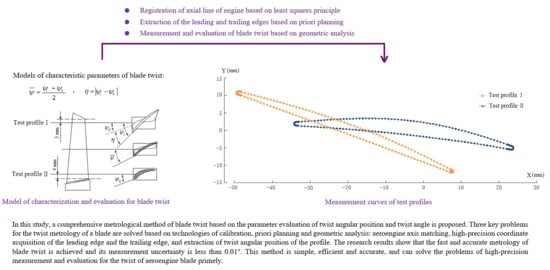
The method of characterization and evaluation of the blade twist is described as follows:
(1) As shown in Figure 2, two test profiles I and II are planned on the blade airfoil. Test profile I is set at 3 mm below the minimum radius of the blade tip and test profile II is set at 4 mm above the maximum radius of the blade root.
(2) The twist angular positions ψ I and ψ II of two test profiles are measured respectively based on technologies of a priori planning and geometric analysis.
(3) The characteristic parameters ψ ¯ and η of the blade twist are extracted and calculated. In order to reveal the torsional characteristics of blade comprehensively and intuitively, two evaluation parameters are defined in the study: The twist angular position ψ ¯ of blade characterizes the absolute torsion level of blade relative to the axial line of the engine, which can be determined by average twist angle position of the blade; the twist angle η of blade characterizes the relative torsion degree of the blade itself, which can be determined by the difference value between maximum twist angle position and minimum twist angle position. The mathematical models of parameters ψ ¯ and η are defined respectively as follows:
ψ ¯ = ψ I + ψ II 2
η = | ψ I ψ II |
By optimizing the number and location of the test profiles, the measuring process of the blade twist is effectively simplified and the evaluation efficiency is significantly improved. Based on the parameter evaluations of the twist angular position ψ ¯ and twist angle η , the spatial torsion state of the blade is characterized intuitively and comprehensively. The method proposed in this study has the advantage of being a simple model that delivers a comprehensive evaluation, which authentically reveals the torsion rule of the blade.

2.3. Measurement Method of Blade Twist

In this study, a high-precision special machine for blade measurement shown in Figure 3 is applied to the measurement research of the blade twist. The measuring machine is essentially a four-coordinate laser measurement system, and consists of a four-axis motion platform, a fixture system and a high-precision laser probe. The four-axis motion platform is made up of three linear shaftings of X, Y, and Z with a resolution of 0.1 μm, a rotary shafting of C with a resolution of 0.0002° and a precision CNC (Computer Numerical Control) system [17,18]. The fixture system solves the problems of clamping, positioning and measurement calibration. The high-precision laser probe is designed with a conoscopic holography sensor CP-3 from Optimet (Israel), with a measurement range of −1 mm to +1 mm and a resolution of 0.1 μm. The measuring machine provides a precise hardware platform for the research of the measurement method, and the subsequent experimental verification is also implemented on the high-precision special machine. Coordinate measurements and chord angle extraction with high precision are two key issues to be solved in blade twist measurement.
In order to improve the accuracy and adaptability of the coordinate measurement, an a priori planning measurement method is proposed in this study. Firstly, the test profiles of the blade are measured without theoretical model data by the laser probe, and the theoretical model of the blade is self-constructed based on feature recognition. Then, the measuring path is planned and the sampling strategy is optimized based on the theoretical model solved of blade, and the high-precision acquisition of the blade coordinates is achieved. All coordinates are collected in the positions near the reference distance of the laser probe based on a priori planning technology, thus the depth of measurement approaches 0 mm and the measurement error is no more than 10 μm. In addition, this method is a form-free measurement method and does not need the theoretical model of the blade, which improves the adaptability of the measurement. By optimizing the measurement method, the accuracy level can meet the measuring requirements of aero-turbine blades with a first precision grade. The a priori planning measurement method is an innovation of this study.
In order to improve the measurement accuracy of the chord angle, an algorithm for edge extraction based on sampling optimization and least squares fitting is proposed, which can provide the authentic measurement data for the extraction of the profile chord. The statistical uncertainty of the method is less than 3 μm.
The principle and the process of the blade twist measurement are summarized as follows:
Step 1. Establishment of workpiece coordinate system and registration of engine axis. The workpiece coordinate system is established by scanning the selected section of the mounting column of the fixture, and the axial line of the engine is matched and aligned with the X axis by measuring the side of the base platform of the fixture. In this study, the least squares fitting algorithm is used to process the measured data, which greatly improves the datum accuracy of the twist measurement.
Step 2. Acquisition of coordinates of the test profiles. The high-precision coordinate data is obtained by scanning and measuring test profiles I and II with measurement technology of a priori planning.
Step 3. Feature recognition and profile fitting. By feature recognition and piecewise fitting for the collected coordinate data, the test profiles I and II are extracted, which provides authentic and accurate measurement data for subsequent parameter calculation and evaluation.
Step 4. Basic parameters calculation of test profiles. Based on the fitted profiles I and II, combined with the mathematical model of each parameter, the basic parameters of blade profile, such as leading edge radius, trailing edge radius, leading edge center and trailing edge center, are calculated.
Step 5. Calculation of twist angular positions of two test profiles. Based on the basic parameters of the profiles calculated in Step 4, the twist angular positions ψ I and ψ II are analyzed and calculated with the technology of geometric analysis.
Step 6. Evaluation of blade twist. Based on the solutions of ψ I and ψ II obtained in Step 5, the characteristic parameters of blade twist ψ ¯ and η are calculated using Equations (1) and (2). Thus, the spatial torsion state of blade is characterized and evaluated comprehensively with twist angular position ψ ¯ and twist angle η .
The measuring process of blade twist on the high-precision special machine for blade measurement is shown in Figure 4.

3. Analysis of Key Technologies

3.1. Registration Method of Axial Line of Engine Based on Least Squares Principle

In order to locate the axial line of engine quickly and accurately, a fixture for blade clamping as shown in Figure 5 is designed in this study.
The fixture is composed of three exact centrosymmetric components: the mounting column, the base platform and the pressing plate. The high-precision positioning and clamping of blade is achieved using an adjustable dovetail groove structure formed by sides of the pressing plate and base platform. In addition, the dowel datum planes of the measured blade are closely clamped with the sides of pressing plate, which guarantees the parallel relation between axial line of engine and side of base platform. Therefore, the precise adjustment of the engine axis can be realized by measuring and rotating the side of base platform.
The registration method of axial line of engine based on the fixture for blade clamping shown in Figure 5 is described as follows:
(1) Establishment of workpiece coordinate system. Firstly, a set of coordinates are obtained by measuring the selected profile of the mounting column with the probe system along the X-axis direction. Then, the center coordinates and radius of the mounting column are solved based on the least squares circle fitting for the collected coordinate data. Finally, through motion control, the workpiece coordinate system O-XYZ is established on the axis of the mounting column as shown in Figure 5.
(2) Registration of the engine axis. As shown in Figure 6, the axial line of the engine is matched and aligned with the X axis in three steps. Firstly, a line with a length of 50 mm on the side of base platform in X-axis direction is selected, and a set of coordinates are collected by measuring the planned profile with the probe system in spacing of 2 mm. Then, the slope and intercept are calculated based on least squares linear fitting for the measured data and the registration angle α between the normal line on the side of the base platform and Y axis is obtained. Finally, the angle α is adjusted to zero by the rotary motion of the measuring machine to realize the registration of engine axis.

3.2. Extraction Method of the Leading and Trailing Edges Based on A Priori Planning

The high-precision extraction of the leading and trailing edges is the primary and key issue to be solved of blade twist measurement. The leading and trailing edges of the blade have characteristics of high geometric accuracy, ultra-thin shape and large curvature fluctuation, which cause great difficulties with the machining and measurement of blade edges [19,20]. Influenced by the probe accuracy and system scanning resolution, the existing measuring method of blade edges has disadvantages of large coordinate error, serious fluctuation or even loss of measured data.
In order to solve the technical problem of the blade edge measurement, a new measuring method for leading and trailing edges based on a priori planning is proposed in this study. The blade edges are measured in three steps using the method proposed in this study. Firstly, the test profiles are scanned by the probe system in the absence of the theoretical model of measured blade [21,22], and a set of a priori coordinates of P s i ( x s i , y s i , z s i ) for planning are obtained, i = 1 , 2 , , N . Then, the number and location of measurement points are optimized based on the feature recognition and sampling strategy analysis for the a priori coordinates collected [23,24]. Finally, according to the optimization results, the probe system is controlled to collect data at the planned positions, and the precise coordinates of P m i ( x m i , y m i , z m i ) of each measuring point are obtained.
The curves of the leading and trailing edges measured by priori planning technology are shown in Figure 7. It can be concluded from Figure 7 that the sampling strategy is optimized automatically without the theoretical model of the measured blade, and the edge features of the blade are extracted effectively by planning measuring points densely at the edge parts with larger curvature variation. Based on the least squares fitting for the precision coordinates collected of the leading and trailing edges, parameters of center coordinates and radius of the blade edge can be solved quickly and accurately. The high-precision measurement of the leading and trailing edges based on the technologies of a priori planning and least squares fitting is a key issue and innovation, which overcomes the influence of the error factors such as the movement accuracy of the machine tool and provides the authentic measurement data for the extraction of the profile chord and subsequently the calculation of twist angular position.
The adaptive optimization of sampling strategy is achieved through form-free and a priori planning measurement of the measured blade in this method. In addition, coordinates of P m i ( x m i , y m i , z m i ) are collected at the planned positions, where the depth of field is close to zero, thus the inclination error is effectively reduced and the measurement accuracy is improved greatly [25,26]. The research results show that the measuring method based on a priori planning has the characteristics of being high precision and form-free. The comprehensive measurement accuracy reaches the level of 10 μm, which can meet the measuring requirements of the leading and trailing edges of ultra-thin blade.

3.3. Extraction Algorithm of Twist Angular Position of the Profile Based on Geometric Analysis

As shown in Figure 8, O 1 ( x 1 , y 1 ) and O 2 ( x 2 , y 2 ) represent the centers of the leading and trailing edges respectively, R q and R h represent the radius of the leading and trailing edges respectively, and the line of EF is the profile chord. The axial line of engine is parallel to X axis after registration, thus the mathematical model of twist angular position of the profile can be defined as follows:
ψ = β + θ
where β is the angle between the center line O 1 O 2 of the leading and trailing edges and X axis, θ is the angle between the profile chord and the center line O 1 O 2 . By geometric analysis, we can get the mathematical models of parameters θ and β as follows:
θ = arcsin   | R q R h | ( x 2 x 1 ) 2 + ( y 2 y 1 ) 2
β = arctan   y 2 y 1 x 2 x 1
Based on the least squares fitting technology, the center coordinates and radius of the blade edges are solved. Then the twist angular position of the profile can be calculated using Equations (3)–(5).

4. Experiments and Analysis

Taking an aeroengine blade as the measured object, the method for the blade twist measurement proposed in the paper has been experimented and studied on the measuring machine of the blade shown in Figure 3. The experiment is carried out according to the measurement process shown in Figure 4.

4.1. Measurement and Analysis of Test Profiles

The test profiles have been measured based on the technology of a priori planning measurements, and some of the experimental data is shown in Table 1. In Table 1, all coordinates are obtained in workpiece coordinate system after registration with engine axis. The measurement curves of the test profiles are shown in Figure 9. As can be concluded from Figure 9, the closed contour curves of the test profiles are achieved based on the adaptive adjustment of the distribution of measuring points and the depth of field, the edge features of the blade are extracted effectively by planning measuring points densely at edges with larger curvature variation, and the exact form and position relationship of the test profiles are intuitively represented. The experimental results show that the a priori planning measurement method proposed in the study improves the adaptability of the coordinate measurement by self-constructing the theoretical model of the blade, and provides accurate data for the calculation of the blade edge parameters and the extraction of the twist characteristic quantity.

4.2. Measurement and Evaluation of Parameters of Leading and Trailing Edges

The leading and trailing edges of the blade studied in this paper are constructed by circular arc, and its mathematical model is as follows:
x 2 + y 2 + a x + b y + c = 0
where a , b , c are the model coefficients, which can be solved by the least squares fitting algorithm based on coordinates collected of the leading and trailing edges [27,28]. Then the parameters of leading and trailing edges can be determined by the following equations:
{ x 0 = a / 2 y 0 = b / 2 r = a 2 + b 2 4 c / 2
where ( x 0 , y 0 ) are the center coordinates of the leading and trailing edges, and r is the radius.
The test profiles I and II have been measured five times using the method of the a priori planning measurement, and the coordinates collected of blade profiles are used for the accuracy analysis of the leading and trailing edges. Based on the five sets of coordinates collected and the least squares circle fitting algorithm, the parameters and measurement standard deviations of the leading and trailing edges are solved as shown in Table 2. In Table 2, R q is the leading edge radius, ( x 1 , y 1 ) are the center coordinates of the leading edge, R h is the trailing edge radius, ( x 2 , y 2 ) are the center coordinates of the trailing edge, m 1 ~ m 5 represent five sets of parameters solved of blade edges, μ represents the average value of measurements, and σ represents the standard deviation of measurements.
The measurement results show that the algorithm for edge extraction based on sampling optimization and least squares fitting presented in the study is effective, the parameters of the blade edges are extracted exactly, and the statistical uncertainty of the measurements is as follows. The accurate measurement of the leading and trailing edges provides the authentic data for the extraction of profile chord.
{ u A ( x 0 ) = 0.003   mm u A ( y 0 ) = 0.002   mm u A ( r ) = 0.003   mm

4.3. Measurement and Evaluation of Blade Twist

Based on the form and position parameters solved of the leading and trailing edges, the characteristic quantities ψ ¯ and η of blade twist are calculated using Equations (1)–(5) as follows:
R q = 0.459 ,   x 1 = 48.809 ,   y 1 = 10.852 R h = 0.417 ,   x 2 = 7.336 , y 2 = 11.585 } ( 4 )   ( 5 ) Formulas θ 1 = 0.04 ° β 1 = 21.783 ° } Formula   ( 3 ) ψ I = 21.743 ° R q = 0.536 ,   x 1 = 33.613 ,   y 1 = 1.966 R h = 0.541 ,   x 2 = 23.228 ,   y 2 = 5.024 } ( 4 )   ( 5 ) Formulas θ 2 = 0.005 ° β 2 = 7.011 ° } Formula   ( 3 ) ψ II = 7.006 ° } ( 1 )   ( 2 ) Formulas ψ ¯ = 14.375 ° η = 14.737 °
The uncertainty of the measurement of blade twist is analysed as follows:
(1) Uncertainty of parameter β :
The mathematical model of combined standard uncertainty of parameter β can be derived from the Equation (5):
u C ( β ) = 1 1 + M 2 × [ 1 A 2 × u 2 ( y 2 ) + 1 A 2 × u 2 ( y 1 ) + ( B A 2 ) 2 × u 2 ( x 2 ) + ( B A 2 ) 2 × u 2 ( x 1 ) ] 1 2
where A = x 2 x 1 ,   B = y 2 y 1 ,   M = B / A .
The parameters of blade edges and their statistical uncertainties shown in Table 2 are brought into Equation (9), then the result of uncertainty evaluation of β is as follows:
{ u C ( β 1 ) = 5.065 × 10 5 deg u C ( β 2 ) = 4.985 × 10 5 deg
(2) Uncertainty of parameter θ :
The mathematical model of combined standard uncertainty of parameter θ can be derived from the Equation (4):
u C ( θ ) = K 1 × [ K 2 × u 2 ( R q ) + K 2 × u 2 ( R h ) + K 3 × u 2 ( y 2 ) + K 3 × u 2 ( y 1 ) + K 4 × u 2 ( x 2 ) + K 4 × u 2 ( x 1 ) ] 1 2
In Equation (11), the coefficients K 1 ~ K 4 are determined by the following equations:
{ K 1 = [ 1 ( R q R h ) 2 ( x 2 x 1 ) 2 + ( y 2 y 1 ) 2 ] 1 2 K 2 = 1 ( x 2 x 1 ) 2 + ( y 2 y 1 ) 2 K 3 = ( R q R h ) 2 × ( y 2 y 1 ) 2 [ ( x 2 x 1 ) 2 + ( y 2 y 1 ) 2 ] 3 K 4 = ( R q R h ) 2 × ( x 2 x 1 ) 2 [ ( x 2 x 1 ) 2 + ( y 2 y 1 ) 2 ] 3
The parameters of blade edges and their statistical uncertainties shown in Table 2 are brought into Equations (11) and (12), then the result of uncertainty evaluation of θ is as follows:
{ u C ( θ 1 ) = 7.016 × 10 5 deg u C ( θ 2 ) = 7.408 × 10 5 deg
(3) Uncertainty of blade twist:
The mathematical models of combined standard uncertainties of parameters ψ ¯ and η can be derived respectively from Equations (1)–(3):
u C ( ψ ¯ ) = 1 2 [ u C 2 ( β 1 ) + u C 2 ( θ 1 ) + u C 2 ( β 2 ) + u C 2 ( θ 2 ) ] 1 2
u C ( η ) = [ u C 2 ( β 1 ) + u C 2 ( θ 1 ) + u C 2 ( β 2 ) + u C 2 ( θ 2 ) ] 1 2
The uncertainty analysis results of parameters β and θ are brought into Equations (14) and (15), then the uncertainties of parameters ψ ¯ and η are obtained as follows:
{ u C ( ψ ¯ ) = 0.004 ° u C ( η ) = 0.008 °
The experimental results show that the absolute twist angular position ψ ¯ of blade relative to the engine axis is −14.375° and its uncertainty of measurement is 0.004°, the relative twist angle η of blade itself is 14.737° and the measurement uncertainty is 0.008°. The measurement method of blade twist presented in this study is effective and accurate, the problems of measurement and evaluation of the blade twist are solved commendably using technologies of calibration, a priori planning and geometric analysis.

4.4. Deviation Assessment of the Method

In order to verify the reliability of the measurement results, the verification measurement of the test profiles is carried out on a high-precision four-coordinate measuring machine of JE42, whose overall measurement accuracy is less than 2 μm. The four-coordinate measuring machine of JE42 collects coordinate data with a high-precision contact probe of GT31 from TESA Switzerland, and its technical parameters are provided in Table 3. After coordinate transformation and registration of the measured data, the measurement curves of test profiles are shown in Figure 10.
The experimental data collected by JE42 is processed based on least squares fitting algorithm, and the form and position parameters of the leading and trailing edges for test profiles I and II are solved as shown in Table 4.
Based on the parameters solved of the leading and trailing edges and evaluation model of blade twist proposed in the study, the results are as follows:
{ ψ ¯ 0 = 14.356 ° η 0 = 14.776 °
where ψ ¯ 0 and η 0 represents respectively the twist angular position and twist angle measured by JE42.
Taking the measurement results of JE42 as the agreed true value, the measurement deviation of twist angular position is less than 0.02°, and the measurement deviation of twist angle is less than 0.04°. The experiments show that the method proposed in this study can achieve high-precision and form-free measurement of blade twist.

4.5. Analysis and Comparison of Measurement Methods

The common methods for blade twist measurement are analyzed and compared as shown in Table 5. It can be concluded as follows:
(1) CMM collects blade coordinates point by point using a contact probe and the measurement accuracy can be improved through path planning and sampling optimization, but is limited by the measuring principle and radius of probe ball. The CMM method is insufficient in adaptability, efficiency and edge measurement accuracy.
(2) CORE DS collects coordinates efficiently by scanning the blade profile using the laser sensor and the measurement accuracy can reach 10 μm level through inclination error compensation. However, it still has some problems in adaptability, evaluation algorithm and measurement accuracy.
(3) The method for the blade twist measurement proposed in the study is form-free, efficient and accurate, and can solve the problems of high-precision measurement and evaluation for the twist of aeroengine blade primely.

5. Conclusions

In this paper, the precision measurement method of the twist of the aeroengine blade is studied, and a comprehensive measuring method of the blade twist based on evaluations of twist angular position and twist angle is proposed. Three key problems for the twist metrology of a blade are solved based on technologies of calibration, a priori planning and geometric analysis: aeroengine axis matching, high-precision coordinate acquisition of the leading and trailing edges, and extraction of twist angular position of the profile. The contents and conclusions of the innovative research are as follows:
(1) A simple and efficient method for registration of the engine axis based on the special fixture and least squares algorithm is studied, which achieves the fast establishment of the measurement benchmark of blade twist and improves the datum positioning accuracy significantly.
(2) A high-precision method for the measurement of the leading and trailing edges based on a priori planning is proposed in this study, and the technical difficulties of blade edge measurement are solved. By optimizing the sampling strategy automatically, the measurement accuracy is improved significantly and the edge features of blade are extracted effectively, which provides authentic measurement data for the twist evaluation.
(3) A high-precision extraction method for blade edges based on sampling optimization and least squares fitting is presented, which can overcome the fluctuation error of measured data and extract the parameters of blade edges exactly. The statistical uncertainty of the method is less than 3 μm.
(4) An algorithm for parameters calculation of the blade twist based on geometric analysis is analyzed in this study, which solves the problem of characterization and evaluation of aeroengine blade twist.
(5) Taking an aeroengine blade as the test object, the measuring method is studied experimentally. The results show that the metrological method of blade twist presented in this study is effective and its measurement uncertainty is less than 0.01°. This method is form-free, efficient, accurate, and can solve the problems of high-precision measurement and evaluation for the twist of aeroengine blade primely.

Author Contributions

X.L. and Z.S.; methodology, X.L.; software, X.L.; validation, X.L.; formal analysis, X.L.; investigation, X.L.; resources, Z.S.; data curation, Z.S.; writing—original draft preparation, X.L.; writing—review and editing, X.L.; visualization, X.L.; supervision, Z.S.; project administration, Z.S.; funding acquisition, Z.S. All authors have read and agreed to the published version of the manuscript.

Funding

This research was funded by the Key Project of National Natural Science Foundation of China, grant number 51635001. The APC was funded by 51635001.

Acknowledgments

This work was supported by the Key Project of National Natural Science Foundation of China (Grant No. 51635001) and the Fundamental Research Funds for the Central Universities of China (Grant No. 3142018054 and No. 3142019055).

Conflicts of Interest

The authors declare no conflict of interest.

Nomenclature

ψ twist angular position of profile, deg
ψ ¯ twist angular position of blade, deg
η twist angle of blade, deg
ψ I twist angular position of test profile I, deg
ψ II twist angular position of test profile II, deg
α registration angle of engine axis, deg
P s i ( x s i , y s i , z s i ) A priori coordinates, mm
P m i ( x m i , y m i , z m i ) precise coordinates, mm
x 1 , y 1 center coordinates of leading edge, mm
x 2 , y 2 center coordinates of trailing edge, mm
R q radius of leading edge, mm
R h radius of trailing edge, mm
β angle between the center line O 1 O 2 of the leading and trailing edges and X axis, deg
θ angle between the profile chord and the center line O 1 O 2 , deg
Xabscissas of measuring points on test profile, mm
Yordinates of measuring points on test profile, mm
μ average value of measurements, mm
σ standard deviation of measurements, mm

References

  1. Wang, H.S.; Yuan, X.; Yue, G.Q.; Zhong, J.J.; Wang, Z.Q. Effects of Curved Blade Stacking Line on the Aerodynamic Performance of Compressor Cascade. J. Aerosp. Power 2002, 17, 327–331. [Google Scholar]
  2. Gao, L.M.; Cai, Y.T.; Zeng, R.H.; Tian, L.C. Effects of Blade Machining Error on Compressor Cascade Aerodynamic Performance. J. Propuls. Technol. 2017, 38, 525–531. [Google Scholar]
  3. Gao, L.M.; Cai, Y.T.; Hao, Y.P.; Zhao, X.; Tian, L.C. Experimental Investigation on Aerodynamic Performance of Compressor Blade Considering Manufacturing Error. J. Propuls. Technol. 2017, 38, 1761–1766. [Google Scholar]
  4. Zhang, W.H.; Zou, Z.P.; Li, W.; Luo, J.Q.; Pan, S.N. Unsteady Numerical Simulation Investigation of Effect of Blade Profile Deviation on Turbine Performance. Acta Aeronaut. Astronaut. Sin. 2010, 31, 2130–2138. [Google Scholar]
  5. Cheng, C.; Wu, B.H.; Zheng, H.; Gao, L.M. Effect of blade machining errors on compressor performance. Acta Aeronaut. Astronaut. Sin. 2020, 41, 623237. [Google Scholar]
  6. Yu, X.L.; Ye, P.Q. Parameters Identification of the Vane Based on MATLAB. Aviat. Maint. Eng. 2009, 4, 56–58. [Google Scholar]
  7. Peng, Z.G.; Li, W.L. Feature Parameters Extraction of the Blade Surface based on the Improved Convex Hull Algorithm. Equip. Manuf. Technol. 2012, 1, 37–43. [Google Scholar]
  8. Mao, C.L. Inspection of Aero Engine Blade Cross-Sectional Feature Parameters; Tianjin University: Tianjin, China, 2015. [Google Scholar]
  9. Shi, X.Q.; Wu, B.H.; Zhang, D.H. Development Tendency of Inspecting Technology for Aeroengine Blade. Aeronaut. Manuf. Technol. 2015, 12, 80–84. [Google Scholar]
  10. Su, J.; An, Z.Y.; Yu, Y.F.; Bai, J. A New Synchronous Measurement Method for Torsion and Bending Deformation of Engine Blade. J. Exp. Mech. 2017, 2, 279–285. [Google Scholar]
  11. Shi, J.H.; Liu, P. High Efficiency Measurement Method for Large-size Aeroengine Blade Profile. Acta Metrol. Sin. 2018, 5, 605–608. [Google Scholar]
  12. Bu, K.; Zhang, X.; Ren, S.; Qiu, F.; Tian, G. Research on Influence of CMM Sampling Points on Detection of Feature Parameters for Turbine Blade. J. Northwest. Polytech. Univ. 2019, 4, 767–773. [Google Scholar] [CrossRef]
  13. Sun, B.; Li, H.Z.; He, D.F.; Liu, H.T.; Wang, J.H. Profile Error Detection and Evaluation of Aero-engine Blade. Tool Eng. 2019, 4, 103–106. [Google Scholar]
  14. Li, B.; Li, F.; Liu, H. A measurement strategy and an error-compensation model for the on-machine laser measurement of large-scale free-form surfaces. Meas. Sci. Technol. 2014, 1, 5204–5214. [Google Scholar] [CrossRef]
  15. Aviation Industry Standard of People’s Republic of China. Label Tolerance and Surface Roughness of Blade Profile HB 5647-98; Aviation Industry Corporation of China: Beijing, China, 1999. [Google Scholar]
  16. National Military Standard of People’s Republic of China. Aircraft Gas Turbine Powerplant Terminology and Symbols GJB 2103A-97; Commission of Science, Technology and Industry for National Defense: Beijing, China, 1998. [Google Scholar]
  17. Shao, W.; Guo, H.R.; Wu, Y.; Zhou, A.W.; Peng, P. Measurement method for aeroengine blade based on large reflection angle noncontact sensing technology. Opt. Eng. 2018, 57, 054115. [Google Scholar] [CrossRef]
  18. Li, X.Z.; Shi, Z.Y.; Chen, H.F.; Lin, J.C. Current Status and Trends of Aeroengine Blade Profile Metrology. J. Beijing Univ. Technol. 2017, 43, 557–565. [Google Scholar]
  19. Liu, G.D.; Pu, Z.B.; Zhang, Z.; Sun, Y.B. New method for the measurement of aeroengine blade edge. Proc. SPIE 2002, 4929, 475–480. [Google Scholar]
  20. Li, Y. The Aero-Engine Blade Edge Detection based on Color Image Wavelet Sub-pixel Method. Aeronaut. Sci. Technol. 2009, 1, 25–27. [Google Scholar]
  21. Shi, Z.Y.; Zhang, B.; Lin, J.C. Design of measuring machine for complex geometry based on form-free measurement mode. Chin. J. Sci. Instrum. 2012, 33, 1377–1384. [Google Scholar]
  22. Shi, Z.Y.; Zhang, B.; Li, X.M. Form-Free Measurement Mode in Precision Engineering. Nanotechnol. Precis. Eng. 2012, 10, 132–136. [Google Scholar]
  23. Li, X.Z.; Shi, Z.Y.; Li, K.; Li, Y.K. A measuring method for the leading and trailing edges of blade based on feature modelling. In Proceedings of the IEEE the 14th International Conference on Electronic Measurement & Instruments, Changsha, China, 1–3 November 2019; Volume 11, pp. 680–685. [Google Scholar]
  24. Zhang, H.; Shi, Z.Y.; Zhang, B. Study on 3D Geometric Shape Discriminant and Form Error Evaluation. Chin. J. Sci. Instrum. 2014, 35, 1217–1222. [Google Scholar]
  25. Sun, B.; Li, B. Laser Displacement Sensor in the Application of Aero-Engine Blade Measurement. IEEE Sens. J. 2016, 16, 1377–1384. [Google Scholar] [CrossRef]
  26. Li, X.Z.; Shi, Z.Y.; Li, Y.K.; Lin, J.C. Form-free high-precision probe system of blade based on the synchronization of planning and measurement. Chin. J. Sci. Instrum. 2018, 39, 9–17. [Google Scholar]
  27. Li, Q.; Huang, X.; Li, S.G. A laser scanning posture optimization method to reduce the measurement uncertainty of large complex surface parts. Meas. Sci. Technol. 2019, 30, 105203. [Google Scholar] [CrossRef]
  28. Li, X.Z.; Shi, Z.Y.; Li, Y.K.; Lin, J.C. A High-precision Form-free Metrological Method of Aeroengine Blades. Int. J. Precis. Eng. Manuf. 2019, 20, 2061–2076. [Google Scholar]
Figure 1. Definition diagram of the twist angular position of profile.
Applsci 10 04130 g001
Figure 2. Model of characterization and evaluation for blade twist.
Applsci 10 04130 g002
Figure 3. High-precision special machine for blade measurement.
Applsci 10 04130 g003
Figure 4. Flowchart of blade twist measurement.
Applsci 10 04130 g004
Figure 5. Fixture for blade clamping.
Applsci 10 04130 g005
Figure 6. Registration diagram of aeroengine axis.
Applsci 10 04130 g006
Figure 7. Curves of the leading and trailing edges extracted based on a priori planning technique.
Applsci 10 04130 g007
Figure 8. Analysis diagram of the mathematical model for the twist angular position of the profile.
Applsci 10 04130 g008
Figure 9. Measurement curves of test profiles.
Applsci 10 04130 g009
Figure 10. Measurement curves of test profiles on JE42.
Applsci 10 04130 g010
Table 1. Measurement coordinates of the test profiles (unit: mm).
Test Profile ITest Profile II
Leading EdgeTrailing EdgeLeading EdgeTrailing Edge
IDXYXYXYXY
1−48.611.2367.1−11.077−33.42.49323.0−4.426
2−48.711.2657.2−11.142−33.52.49623.1−4.445
3−48.811.2867.3−11.192−33.62.47023.2−4.494
4−48.911.2987.4−11.263−33.72.45323.3−4.539
5−49.011.2837.5−11.336−33.82.43323.4−4.588
6−49.111.2507.6−11.409−33.92.41823.5−4.607
7−49.211.1847.7−11.486−34.02.36823.6−4.662
8−49.310.7397.8−11.852−34.12.27923.7−4.771
9−49.210.6637.7−11.891−34.11.75823.7−5.424
10−49.110.5727.6−11.946−34.01.63023.6−5.484
Table 2. Measurement results of the leading and trailing edges (unit: mm).
Test Profile ITest Profile II
Leading EdgeTrailing EdgeLeading EdgeTrailing Edge
R q x 1 y 1 R h x 2 y 2 R q x 1 y 1 R h x 2 y 2
m10.458−48.81010.8530.4177.336−11.5850.537−33.6111.9640.54223.228−5.024
m20.462−48.80510.8520.4167.339−11.5860.538−33.6091.9650.54323.222−5.024
m30.456−48.81210.8530.4197.336−11.5830.534−33.6161.9670.54123.229−5.023
m40.457−48.81010.8500.4157.335−11.5870.534−33.6141.9660.53923.231−5.022
m50.461−48.80610.8530.4187.335−11.5830.535−33.6131.9660.54123.229−5.027
μ0.459−48.80910.8520.4177.336−11.5850.536−33.6131.9660.54123.228−5.024
σ0.0030.0030.0020.0020.0020.0020.0020.0030.0020.0020.0030.002
Table 3. Parameters of four-coordinate measuring machine.
ParametersSpecifications
RangeX: 400 mm, Y: 500 mm, Z: 650 mm, C: 360°
ResolutionX, Y, Z: 0.1 μm, C: 0.0002°
Total accuracy≤2 μm
Table 4. Parameters of the leading and trailing edges measured by JE42 (unit: mm).
Leading EdgeTrailing Edge
R q x 1 y 1 R h x 2 y 2
Test profile I0.461−48.85810.8480.4227.27−11.58
Test profile II0.527−33.6991.9510.5423.176−5.013
Table 5. Analysis and comparison of common methods for blade twist measurement.
CMM of Global Series from HEAXGONCORE DS from WENZELForm-Free and High-Precision Method
Methods of detectionContact measurementNon-contact optical measurementNon-contact and form-free measurement
AdaptabilityPoor adaptability, theoretical model is necessaryPoor adaptability, theoretical model is necessaryGood adaptability, self-constructing theoretical model
EfficiencyLow efficiencyHigher efficiency due to optical scanningThe efficiency is further improved by optimizing measurement method
Accuracy for edge detectionSerious fluctuation or even loss of measured data10 μm levelLess than 10 μm due to a priori planning measurement method

