Article

Electrodeposition Patterned Copper Foam with Micro/Nanostructures for Reducing Supercooling in Water-Based Cool Storage Phase-Change Materials

1
School of Chemical Engineering and Technology, Sun Yat-sen University, Zhuhai 519082, China
2
Guangdong Engineering Technology Research Center for Advanced Thermal Control Material and System Integration, Sun Yat-sen University, Guangzhou 519082, China
3
School of Materials, Sun Yat-sen University, Guangzhou 510009, China
*
Author to whom correspondence should be addressed.
Appl. Sci. 2020, 10(12), 4202; https://doi.org/10.3390/app10124202
Submission received: 18 May 2020 / Revised: 8 June 2020 / Accepted: 11 June 2020 / Published: 19 June 2020
(This article belongs to the Section Materials Science and Engineering)

Abstract

:
Copper foam is widely used in industrial catalysis, flow boiling, and latent heat storage systems. It is expected that a multi-level topology copper foam with micro/nanostructures can further enhance performance. In this study, an electrochemically patterned copper foam with micro/nanostructures was fabricated and used to reduce supercooling in water-based cool storage phase-change materials. By controlling the reaction time (e.g., 195 s, 255 s, and 300 s), the pattern on the copper foam skeleton appeared as granular, dendritic, and coral-like structures, respectively. Compared with a blank group with supercooling of 11 °C during the solidification process, the unmodified copper foam (CF#0s) can reduce it to 7.7 °C. Electrodeposition-patterned copper foam with micro/nanostructures can further reduce supercooling. The average supercooling degree for CF#195s, CF#255s, and CF#300s was further reduced to 5.6 °C, 4.8 °C, and 4.6 °C, respectively. Among them, CF#300s reduced the supercooling and delay time by 60%. This occurred because the micro-nanostructure on the skeleton of copper foam provides abundant nucleation sites for the solidification of water, and surface roughness increases the nucleation rate.

1. Introduction

Copper foam is a new multifunctional material with plenty of connected or unconnected pores that are evenly distributed in the copper matrix. Owing to its excellent electrical conductivity, thermal conductivity, and large specific surface area, it is widely used in electrode materials [1], catalyst [2], and enhanced heat transfer [3,4,5,6,7,8].
There are many methods for modifying copper foam, and some scholars have studied the modification of copper foam structure. Currently, the modification methods of copper foam mainly include anodizing [9], electrochemical corrosion [10], surface oxidation [11,12], and chemical bath deposition [13] methods. Li et al. [9] have used anodization to successfully prepare CuO nanowires, nanosheets, and flower-like nanostructures that are supported on copper foam to obtain an additive-free and binder-free supercapacitor conductive electrode. CuO nanosheets have a nearly vertical orientation on the copper foam substrate, and they are composed of interconnected nanoparticles. Wang et al. [10] have prepared a cactus-like CdS-Cu9S5 structure on copper foam by electrochemical corrosion and hydrothermal methods; the obtained material is a highly efficient catalyst for the photochemical decomposition of water. Owing to its unique cactus-shaped structure, it can provide abundant surface catalytic active sites and many charge transfer channels, which enhances the photo-induced carrier transport and separation during the photoelectrochemical process. To improve the thermal performance, Shi et al. [14] modified the deciduous structure and micro-flower structure on the surface of copper foam using surface oxidation and chemical modification methods to change its wettability, and they studied its pool boiling mechanism. Their results showed that the micro-nanostructure size of the superhydrophilic sample was smaller than that of the superhydrophobic sample, which produced higher contact area and allowed liquid to better penetrate the gap.
To our knowledge, most sediments were mainly CuO and Cu(OH)2. There is little research on the modification of the pure copper multi-level structure on the copper foam surface by electrodeposition, and there are no studies reporting the effect of experimental parameters on the deposited structure. Li et al. [15] used a simple constant current electrodeposition route, and grass-shaped Ni/Cu nanosheet arrays were successfully grown on copper foam. Their experiments showed that the as-deposited grass-like Ni/Cu nanosheet array had excellent electrocatalytic activity and was used for a hydrogen evolution reaction. At the same time, a modified copper foam catalyst also showed high durability. Liu et al. [16] have deposited a three-dimensional porous copper film directly on Cu foam by an electrodeposition method using hydrogen bubbles as a dynamic template. The electrocatalytic activity of hydrazine electrooxidation was tested by linear scanning voltammetry, chronoamperometry, and electrochemical impedance spectroscopy. The authors suggest that the improvement of the electrocatalytic performance of hydrazine electrooxidation was mainly due to the high pore structure of the Cu/Cu foam electrode, which provided a larger surface area and allowed the electrolyte to more easily enter the surface of electrocatalyst.
There have been many studies on the modification of smooth copper surfaces by electrodeposition. Nikolić et al. [17] have studied the morphology of copper deposits obtained under overpotentials belonging to the plateau of the limiting diffusion current density and at higher overpotentials. Copper dendrites form at the overpotential that belongs to the limit diffusion current density plateau. The copper dendrite shape depends on the overpotential of electrodeposition. At higher overpotentials (800 mV and 1000 mV) and greater current density values, porous and very dispersed copper deposits were obtained. Wang et al. [18] have tested the pool boiling heat transfer performance of tree-like structures with different thicknesses. The experiments showed that at lower heat flux densities, the sample thickness did not have a clear effect on pool boiling performance enhancement; when the heat flux density was higher, the boiling effect increased with a decrease in the sample thickness; however, (critical heat flux) CHF increased with an increase in the thickness of the sample. The same author [19] also prepared a micro/nanoporous copper surface using the electrochemical deposition method, which could be used in the evaporator structure of a two-phase heat transfer device. In this study, the original micro-nano bi-porous copper surface and another micro-nano bi-porous copper surface with a micro ball modified by applying a low current density were prepared. It was determined that the microball surface reduced the surface energy of the sample and obtained better heat transfer performance.
In this study, a linearly increasing current density method was used to fabricate the electrodeposition patterned on the copper foam skeleton. It is expected that the electrodeposition patterned copper foam with micro/nanostructures can reduce supercooling in water-based cool storage phase-change materials.

2. Experimental Section

2.1. Sample Preparation and Characterizaition

Figure 1 shows the experimental setup for the preparation of electrodeposition patterned copper foam. A copper sheet was used as the anode, and a copper foam was used as the cathode. The copper foam ((porous per inch) PPI: 95, purity: 99%) was provided by the Kunshan Guangjiayuan Co. Ltd. (Kunshan, China). The copper foam had a thickness of 1.0 mm, and it was cut into 40 mm (L) × 20 mm (W) pieces. The electrolytes were composed of 0.2 M CuSO4, 1.5 M H2SO4, and 0.5 M Na2SO4. CuSO4·5H2O, H2SO4, and Na2SO4 were all of analytical grade, and they were obtained from the Sinopharm Chemical Reagent Co. Ltd. (Shanghai, China). The distance between the anode and cathode was 2 cm. Both the anode and cathode were connected to a programmable DC power supply (M8852, Maynuo Electronic Co., Ltd., Nanjing, China). During the experiment, the current and voltage data were collected by a computer.
When DC power is applied to the system, the following chemical reaction occurs at the anode:
Cu 2 e - = Cu 2 +
At the same time, the following chemical reaction occurs at the cathode:
Cu 2 + + 2 e = Cu
Thus, copper ion is deposited on the cathode.
If the power is sufficiently high, another chemical reaction happens at the cathode:
2 H + + 2 e = H 2
The hydrogen ion in the electrolyte becomes hydrogen, which generates bubbles in the system. Hydrogen bubbles can help deposited copper to form a porous structure.
Wang et al. [18] have reported that, using the linearly increasing current density method, deposited copper can form a tree-like porous copper, which has abundant dendritic structures. In this study, we used the same method. The initial current density was set to 0.1 A/cm2, and the current density growth rate was set to 0.167 mA/cm2·s. The deposition times for different samples varied from 195 to 300 s, as shown in Table 1. CF#195s, CF#255s, and CF#300s refer to the samples with the deposition times of 195 s, 255 s, and 300 s, respectively. CF#0s refers to the sample with the deposition time of 0 s, which is the original copper foam without any deposition, and it was as a contrast. After deposition, the samples were washed with distilled water and treated at high temperature for 2 h in a reducing atmosphere.
The surface morphology of prepared samples was studied by metallographic microscopy (10XB-PC, Shanghai Optical Instrument Co. Ltd., Shanghai, China) and scanning electron microscopy (SEM, EVO MA10, Carl Zeiss AG, Jena, Germany).
The wettability of different samples was measured by depositing a 4-μL water droplet using a needle. A high-speed camera (Pantom V211, Vision research Co. Ltd., Wayne, NJ, USA) was used to record this phenomenon.

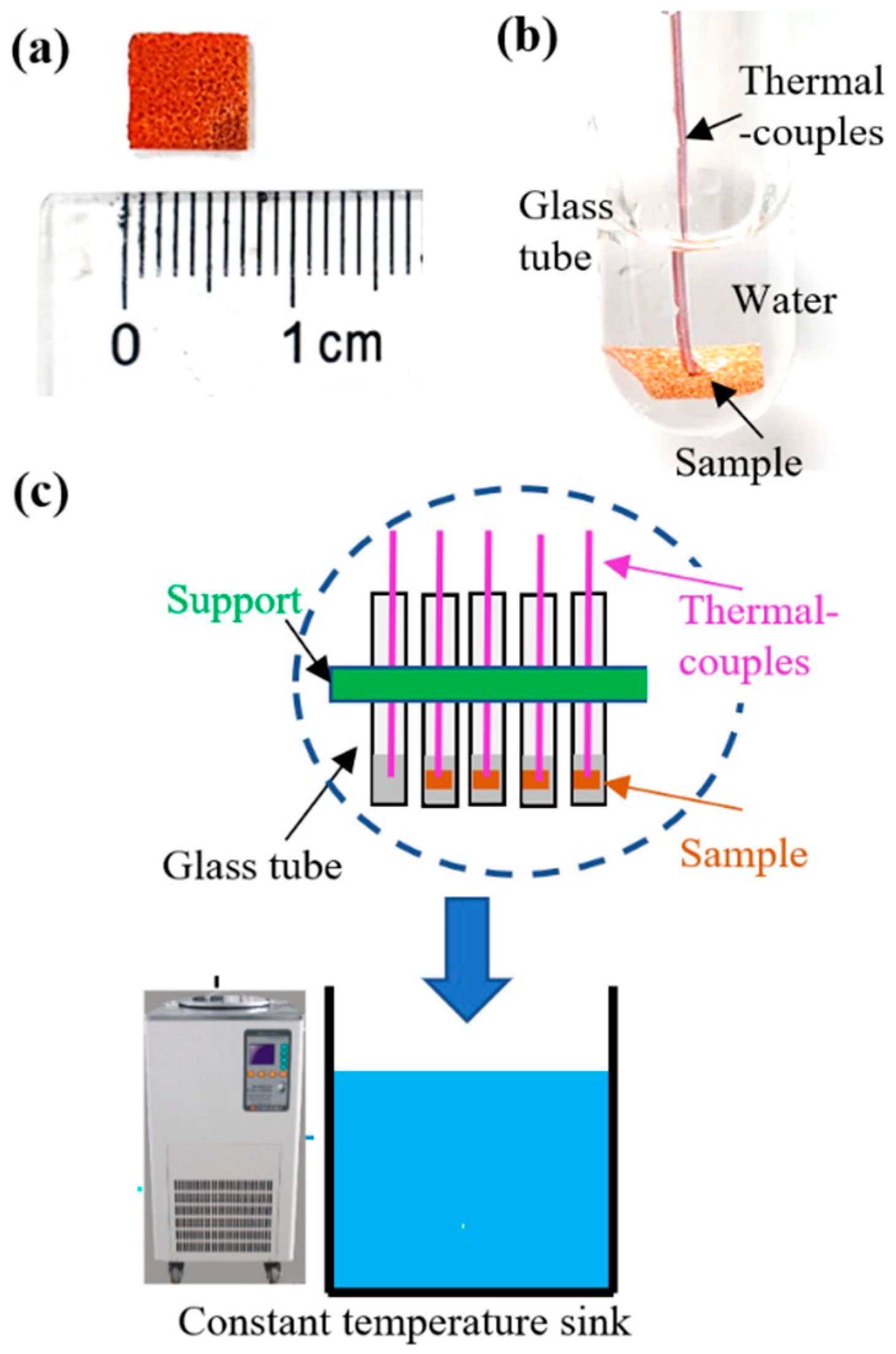
2.2. Test Setup for the Cool Storage Phase-Change Process

Figure 2 shows the test setup for the cool storage phase-change process. The as-prepared sample was cut into a 7 mm × 7 mm piece. A total of 2 mL of deionized water was added into the glass tube as a cool storage phase change medium. A T-type thermocouple with an accuracy of 0.3 °C was embedded in the copper foam, which was positioned 1 cm under the liquid level. Glass tubes with the 4 samples listed in Table 1 were fixed on a support. In addition, a glass tube with only deionized water inside was also fixed in the support as a blank. The support with samples was placed in a constant-temperature sink. When the cool storage phase-change process test cycles began, the setpoint for the constant temperature sink was first set to −20 °C. After all the samples were completely solidified, the setpoint of the temperature for the constant temperature sink was set to 20 °C. After all the samples were completely melted, the setpoint of the temperature for the constant-temperature sink was set to −20 °C again. The solidification and melting processes were repeated 5 times. The output temperature was collected by a data acquisition unit (34980A, Keysight Technologies, Inc., Santa Rosa, CA, USA), and it was then transferred to a computer. A high-speed camera (Pantom V211, Vision research Co. Ltd., USA) was used to record the phase-change process.

3. Results and Discussion

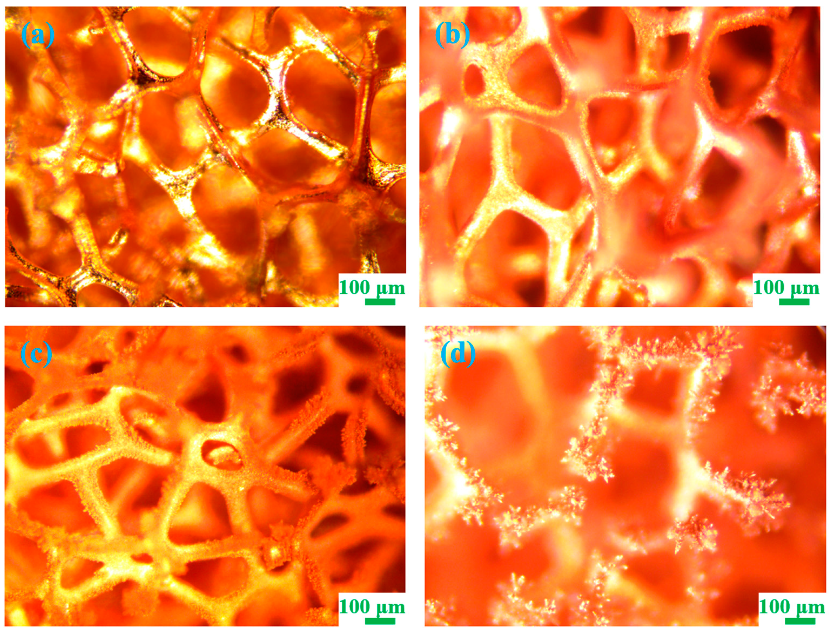
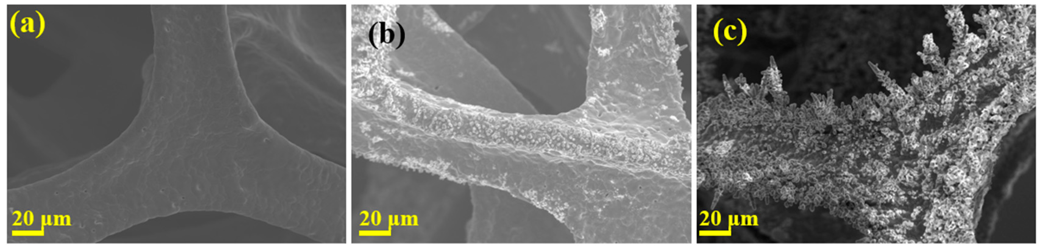
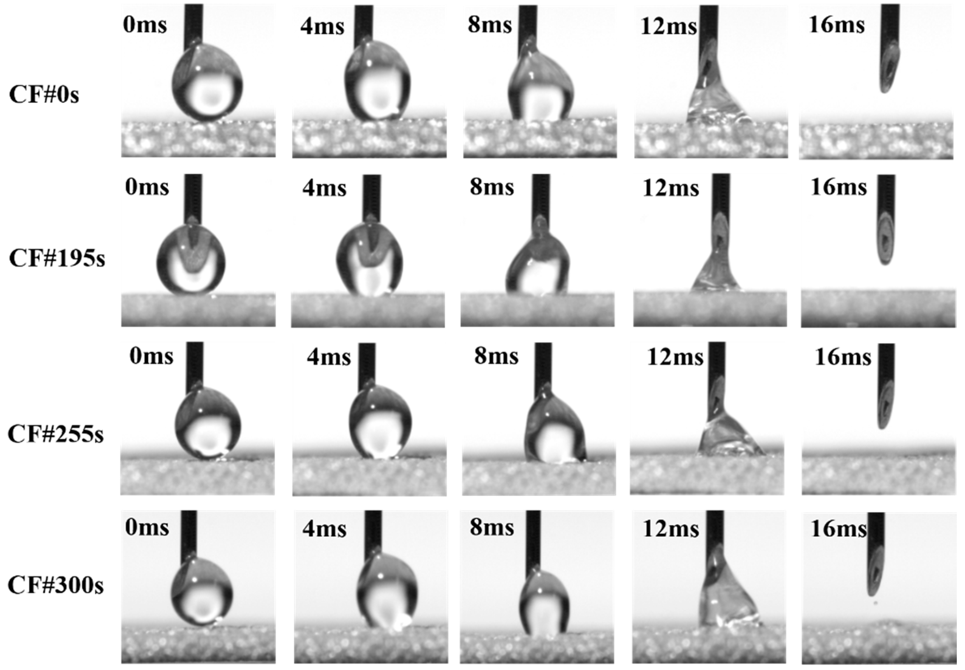
3.1. Morphology of Different Samples

Microscope images of different samples are shown in Figure 3. Without deposition (CF#0s), the skeleton of the copper foam is smooth. When the deposition time is 195 s (CF#195s), many granular structures appear on the copper foam skeleton. However, the granular structures on the skeleton were not very clear. When the deposition time is extended to 255 s (CF#255s), the granular structure on the skeleton becomes a continuous crystal structure. In addition, clear secondary branch structures also grew on some of the primary copper dendrites, which indicated that this method could simultaneously modify the multi-level structure on the copper foam. When the deposition time reached 300 s (CF#300s), the crystal structure became much larger, and it formed a very dense coral-like structure. All crystal branches grew perpendicular to the copper skeleton, and each crystal branch had a clear secondary structure. The obtained result is similar to the one obtained by of Wang et al. [18]. Using the increasing current density method, deposited copper can form perpendicular to the surface, which is similar to tree-like porous copper, which had abundant dendritic structures.

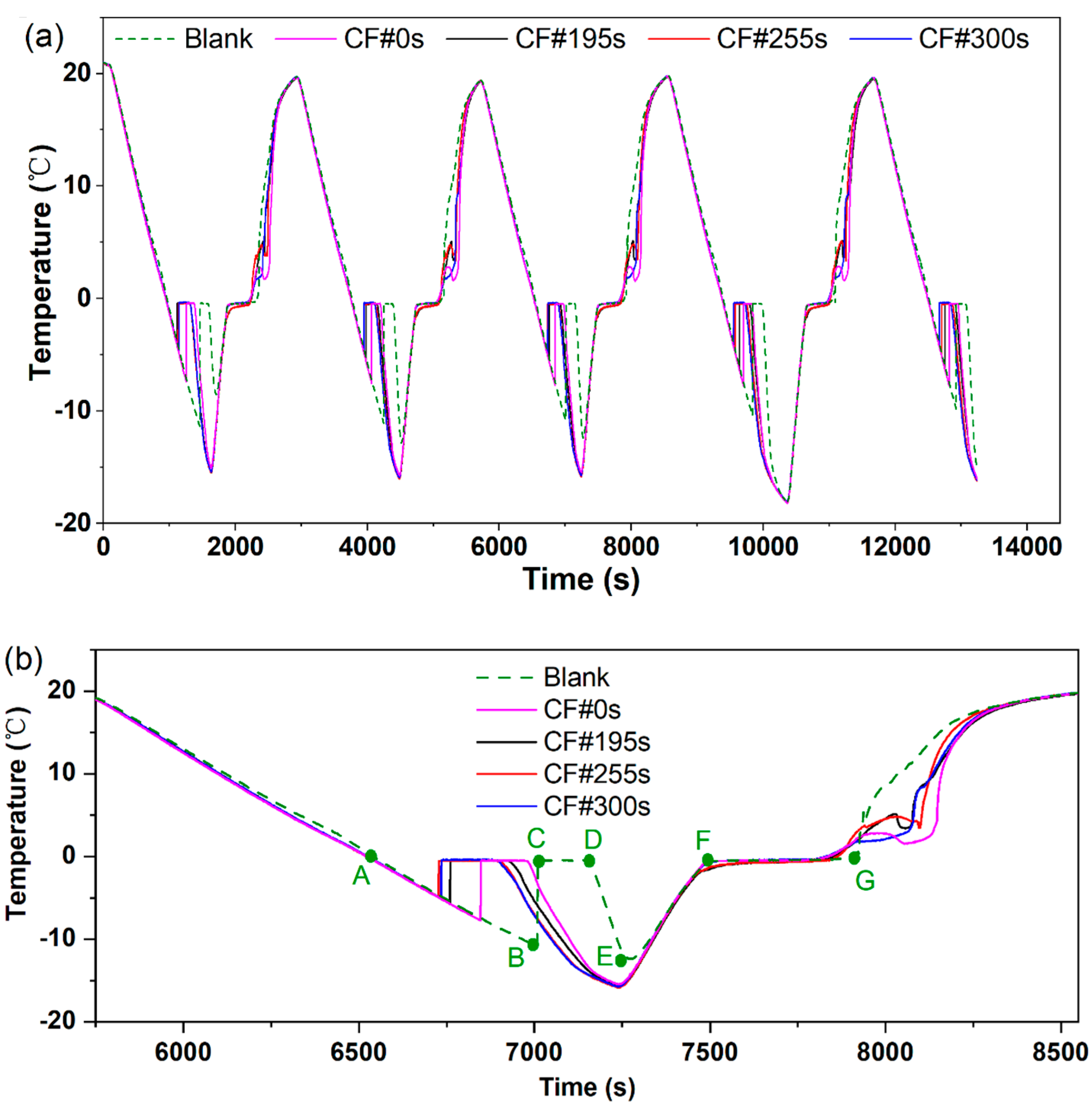
3.2. Temperature Profiles during the Cool Storage Phase-Change Process

Figure 4 shows the temperature profiles during the cool storage phase-change process test cycles. Figure 4a shows the curves repeat well in all cycles. So, we enlarge the 3rd cycle into Figure 4b to see the process clearly. The curves for all samples are quite similar. So, we take the blank sample to describe the process. When the temperature setpoint for the constant-temperature sink was set to −20 °C, the temperature of the sample decreased rapidly. But the water did not immediately solidify at 0 °C. With a decrease in temperature to some value (approximately −11 °C for a blank sample, point B), the temperature suddenly increased to 0 °C (point C) and remained at that value for dozens of seconds (point D). Therefore, water was in the solidification process. When all the water was solidified, the temperature decreased again. Since the temperature of the blank sample needs to be 11 °C lower than the freezing point of water (0 °C), the supercooling for the blank sample is 11 °C.
When the temperature setpoint for the constant temperature sink was set to 20 °C, the temperature rapidly increased. When it reached 0 °C (point F), the temperature remained for dozens of seconds (to point G). This means that water enters the melting process without significant supercooling.
All other samples showed similar curves. All samples had significant supercooling during the solidification process, while there was no considerable supercooling during the melting process. Thus, supercooling during the solidification process will be discussed in detail.

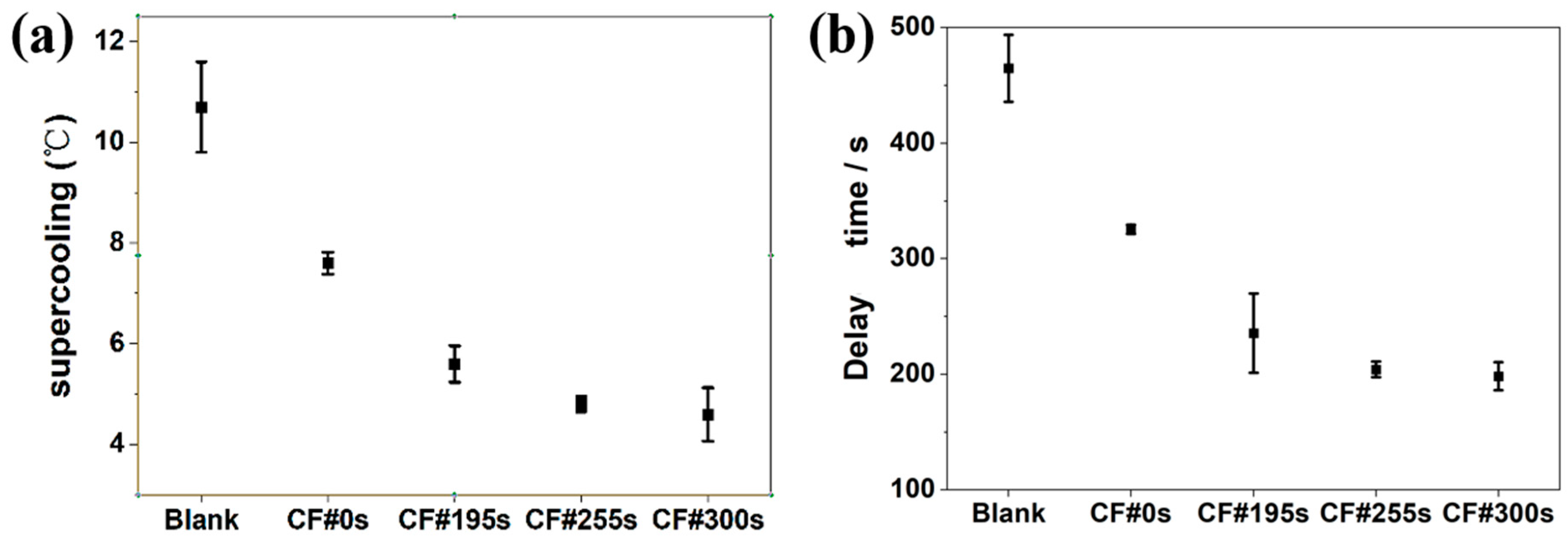
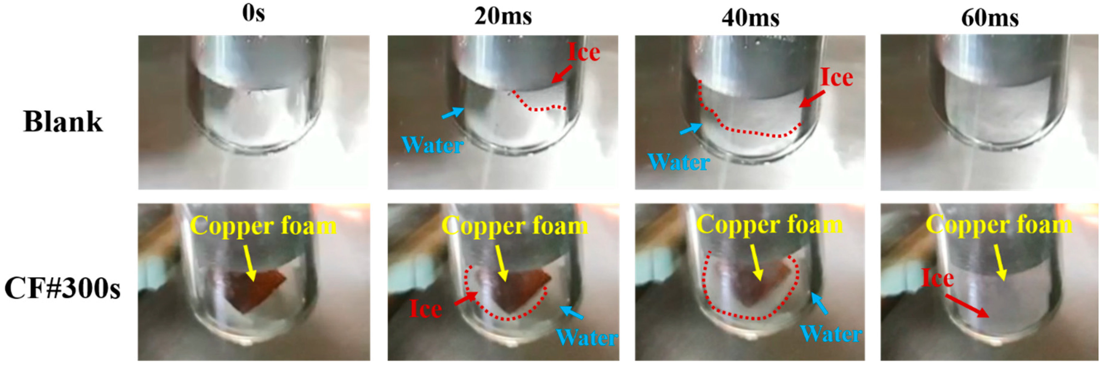
3.3. Supercooling during the Solidification Process

Supercooling during the solidification process for all samples is shown in Figure 5a. The listed values are based on 5 repeat cycles that are shown in Figure 4a. Compared to the supercooling temperature of a blank sample of 11 °C, the supercooling of the copper foam (CF#0s) is only 7.7 °C, which indicates that the copper foam can reduce the supercooling. The results agree with those in previous studies [20]. The more exciting phenomenon is that the electrodeposition patterned copper foam with micro/nanostructures can further reduce supercooling. With an increase in the deposition time, supercooling is reduced. The supercooling temperatures for CF#195s, CF#255s, and CF#300s are approximately 5.6 °C, 4.8 °C, and 4.6 °C, respectively. The lowest supercooling (from CF#300s) was 6.4 °C lower than that of the blank sample, which was a reduction of almost 60%.
The delay time is summarized in Figure 5b. Here, the delay time is the time between the sample reaching 0 °C (point A for blank in Figure 4b and beginning solidification (point C for blank in Figure 4b. The shorter was the delay time, the faster the sample could enter the solidification state. It took approximately 465 s for the blank sample to enter the solidification state. Using copper foam (CF#0s), the delay time was reduced to approximately 325 s. The electrodeposition patterned copper foam with micro/nanostructures can further reduce the delay time. With an increase in deposition time, the delay time is reduced. The delay time for CF#195s, CF#255s, and CF#300s was approximately 235, 204, and 198 s, respectively. The shortest delay time (from CF#300s) was 267 s shorter than that of the blank sample, which was a reduction of almost 60%. The obtained result clearly showed that the electrodeposition patterned copper foam with micro/nanostructures could further reduce both the supercooling and delay time.

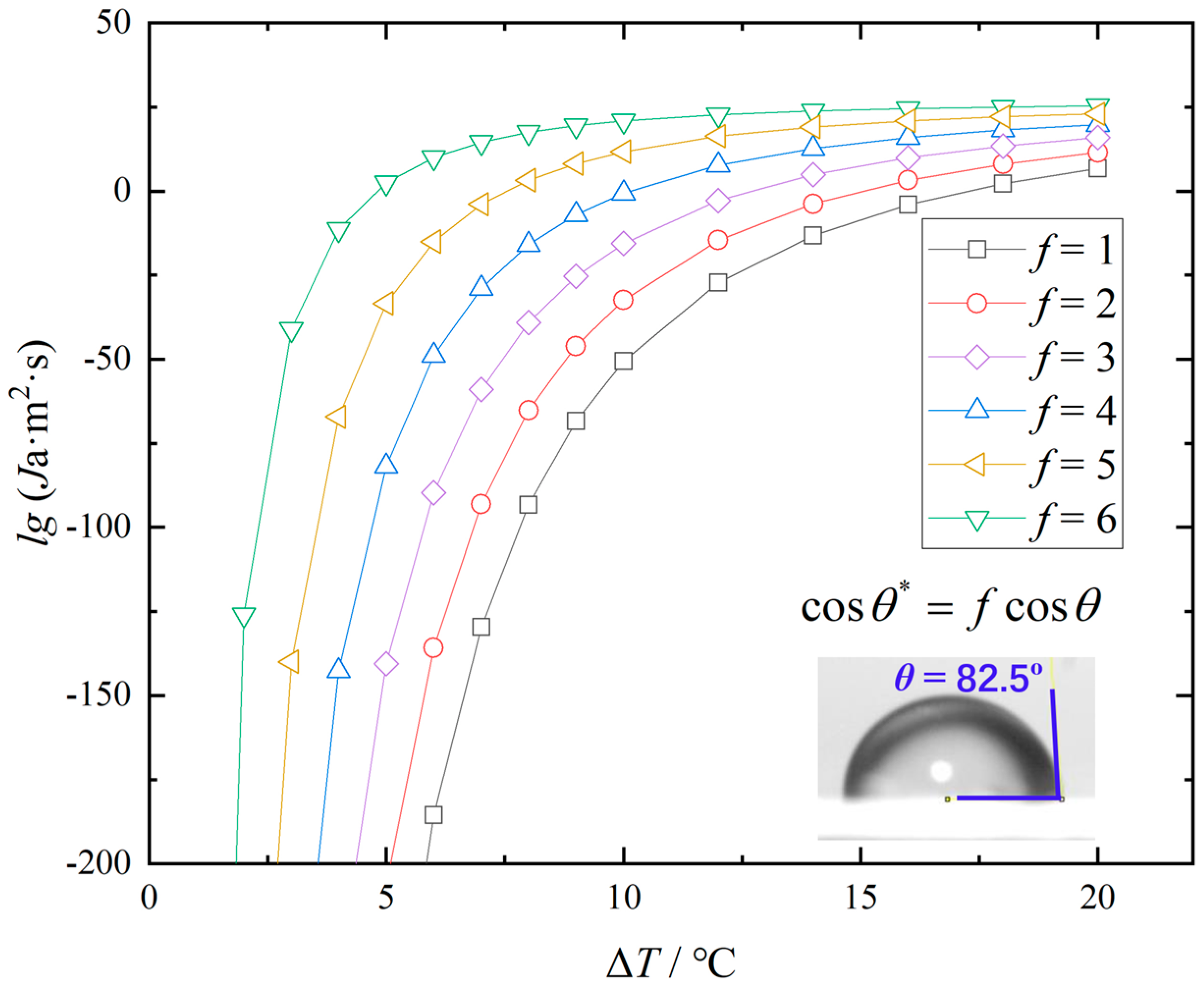
3.4. Mechanism Analysis

There are two main reasons why the electrodeposition patterned copper foam with micro/nanostructures exhibits excellent performance during the solidification of the water-based cool storage phase-change material.
First, as shown in Figure 6, the Cu foam surface is relatively smooth and flat, while the electrodeposition-patterned copper foam has more micro/nanostructure. The electrodeposition-patterned copper foam has many micro/nanostructures, which provide abundant crystal nucleation sites during the solidification of material. With an increase in the deposition time, more micro/nano structures are produced, which is beneficial for nucleation.
Figure 7 shows the solidification process of water in a test tube for the blank group and CF#300s. In the blank group, a crystal nucleus was first generated at the wall on the right side of the test tube, as shown in the photo at 20 ms. After 40 ms, the crystal nucleus grew and diffused to the left side of the test tube. After 60 ms, the crystal nucleus covered the entire test tube. When CF#300s was added to water, it was determined that ice crystals first formed on the surface of copper foam, as shown in the photo at 20 ms. After 40 ms, the entire copper foam was covered with ice, and ice quickly spread to the surrounding area. Finally, solidification was completed after 60 ms. This result demonstrates that copper foam can promote the formation of crystal nucleus.
Second, after the modification of electrodeposition, the micro-nanostructures grown on the copper foam skeletons increased the surface roughness of the copper foam. This made it easier for solid phase crystals to be adsorbed on the surface of the structure, which, to some extent, also eliminate the supercooling degree of phase-change materials with high latent heat. Faucheux et al. [21] have demonstrated that the larger roughness of Al surfaces produced smaller supercooling. Our experimental results confirm this conclusion.
In classical nucleation theory, the heterogeneous ice nucleation rate, Ja, can be predicted by [22]:
J a = c exp [ Δ G A , h e t + Δ G h e t * k T h e t ]
where k is the Boltzmann constant, Thet is the temperature of the system under heterogeneous ice nucleation, and c is the kinetic constant [23], respectively. ΔGA,het and ΔG*het are the diffusion activation energy and total free energy of heterogeneous nucleation, which can be defined as [24,25,26,27,28]:
Δ G A , h e t = k E T h e t 2 ( T h e t T R ) 2
Δ G h e t * = Δ G h o m [ ( 1 cos θ * ) 2 ( 2 + cos θ * ) / 4 ]
where ΔGhom is the homogeneous nucleation energy of ice, and θ* is the apparent contact angle. The constant values of E = 892 K and TR = 118 K were experimentally determined and could be adapted to liquid water between the temperature of 150 and 273 K [29].
The relationship between ΔGhom and supercooling ΔT can be expressed as:
Δ G h o m = 16 π 3 γ 3 T e q 2 ( ρ i c e h f Δ T ) 2
where γ is the surface tension, Teq is the phase change equilibrium temperature, hf represents the latent heat of solidification of water, and ρice is the density of ice.
According to Wenzel’s model [30], which considered a factor of roughness f:
cos θ * = f cos θ
where θ is the intrinsic contact angle. The roughness factor is directly proportional to surface roughness.
The apparent contact angle is essential for the total free energy of heterogeneous nucleation of ice crystals; thus, we try to obtain this parameter using a 4-μL water droplet experiment. As shown in Figure 8, 4-μL water droplets were quickly absorbed into the cavity of the copper foam skeleton within 16 ms for all samples. This result is obtained because the strong liquid absorption performance of copper foam is mainly due to its micrometer-size cavities and high porosity. Thus, we cannot clearly observe the apparent contact angle between water droplets and the surface of copper foam.
However, on the basis of Equations (4)–(9), we can calculate the heterogeneous ice nucleation rate at different supercooling and roughness, which is shown in Figure 9. The inset shows the intrinsic contact angle of a smooth copper surface, which is approximately 82.5°. This value is consistent with those in other studies [28,31,32,33]. Figure 9 shows that at the same supercooling, the nucleation rate increases as the roughness factor f increases. This result demonstrates that at the same nucleation rate, the surface with a larger surface roughness factor f has smaller supercooling. As shown in Figure 6, the sample with a longer deposition time has larger surface roughness; thus, it has a larger nucleation rate at the same supercooling, i.e., it requires smaller supercooling to obtain the same nucleation rate.

4. Conclusions

Using the linearly increasing current density method and by controlling the deposition time, different electrodeposition patterned copper foams with micro/nanostructures were fabricated. The pattern on the copper foam skeleton was granular, dendritic, and coral-like, when the deposition time was 195 s, 255 s, and 300 s, respectively.
The cool storage phase-change experiments showed that the supercooling degree of water in the blank group during solidification was approximately 11 °C, while the copper foam could reduce it to 7.7 °C. The electrodeposition patterned copper foam with micro/nanostructures can further reduce supercooling. The average supercooling degree for CF#195s, CF#255s, and CF#300s were further reduced to 5.6 °C, 4.8 °C, and 4.6 °C, respectively. In addition, the delay time was also greatly shortened after adding the modified sample. When CF#300s is used, the average delay time is shortened by 60% compared to that of the blank group.
There are two reasons why this three-dimensional topological structure can further reduce the degree of subcooling. First, this three-position topological structure provides more nucleation sites for the solidification of water. Second, the nucleation rate increases with an increase in surface roughness.
In addition, this electrodeposition patterned copper foam with micro/nanostructures may also exhibit excellent performance in boiling heat transfer, industrial catalysis, and microreactor owing to its characteristics of large porosity, high thermal conductivity, and the presence of many secondary and even tertiary branches.

Author Contributions

Conceptualization, D.-C.M. and M.X.; methodology, D.-C.M.; validation, M.X., Y.-F.C. and J.-Y.L.; investigation, M.X., Y.-F.C. and J.-Y.L.; writing—original draft preparation, X.M., Y.-F.C. and J.-Y.L.; writing—review and editing, D.-C.M.; supervision, S.-S.L.; project administration, D.-C.M.; funding acquisition, D.-C.M. All authors have read and agreed to the published version of the manuscript.

Funding

This research was funded by National Natural Science Foundation of China under Grant No. 51876226, the Natural Science Foundation of Guangdong under Grant No. 2018A030313482.

Conflicts of Interest

The authors declare no conflict of interest.

References

  1. Carrera-Crespo, J.E.; Huerta-Flores, A.M.; Torres-Martínez, L.M.; Juárez-Ramírez, I. Effect of the Cu foam pretreatment in the growth and inhibition of copper oxide nanoneedles obtained by thermal oxidation and their evaluation as photocathodes. Mater. Sci. Semicond. Process. 2019, 102, 104604. [Google Scholar] [CrossRef]
  2. Pestryakov, A.N.; Lunin, V.V.; Devochkin, A.N.; Petrov, L.A.; Bogdanchikova, N.E.; Petranovskii, V.P. Selective oxidation of alcohols over foam-metal catalysts. Appl. Catal. A Gen. 2002, 227, 125–130. [Google Scholar] [CrossRef]
  3. Manetti, L.L.; Ribatski, G.; de Souza, R.R.; Cardoso, E.M. Pool boiling heat transfer of HFE-7100 on metal foams. Exp. Therm. Fluid Sci. 2020, 113, 110025. [Google Scholar] [CrossRef]
  4. Ji, W.-T.; Li, Z.-Y.; Qu, Z.-G.; Guo, J.-F.; Zhang, D.-C.; He, Y.-L.; Tao, W.-Q. Film condensing heat transfer of R134a on single horizontal tube coated with open cell copper foam. Appl. Therm. Eng. 2015, 76, 335–343. [Google Scholar] [CrossRef]
  5. Xu, Z.G.; Mou, S.; Wang, M.Q.; Gong, Q.; Qin, J. Experimental investigation on pool boiling mechanism of two-level gradient metal foams in deionized water, aqueous surfactant solutions and polymeric additive solutions. Exp. Therm. Fluid Sci. 2018, 96, 20–32. [Google Scholar] [CrossRef]
  6. Yang, J.; Yang, L.; Xu, C.; Du, X. Numerical analysis on thermal behavior of solid–liquid phase change within copper foam with varying porosity. Int. J. Heat Mass Transf. 2015, 84, 1008–1018. [Google Scholar] [CrossRef]
  7. Alhusseny, A.; Al-Zurfi, N.; Nasser, A.; Al-Fatlawi, A.; Aljanabi, M. Impact of using a PCM-metal foam composite on charging/discharging process of bundled-tube LHTES units. Int. J. Heat Mass Transf. 2020, 150, 119320. [Google Scholar] [CrossRef]
  8. Yang, Y.; Ji, X.; Xu, J. Pool boiling heat transfer on copper foam covers with water as working fluid. Int. J. Therm. Sci. 2010, 49, 1227–1237. [Google Scholar] [CrossRef]
  9. Li, Y.; Chang, S.; Liu, X.; Huang, J.; Yin, J.; Wang, G.; Cao, D. Nanostructured CuO directly grown on copper foam and their supercapacitance performance. Electrochim. Acta 2012, 85, 393–398. [Google Scholar] [CrossRef]
  10. Wang, L.; Qian, Y.; Du, J.; Wu, H.; Wang, Z.; Li, G.; Li, K.; Wang, W.; Kang, D.J. Facile synthesis of cactus-shaped CdS-Cu9S5 heterostructure on copper foam with enhanced photoelectrochemical performance. Appl. Surf. Sci. 2019, 492, 849–855. [Google Scholar] [CrossRef]
  11. He, D.; Xing, S.; Sun, B.; Cai, H.; Suo, H.; Zhao, C. Design and construction of three-dimensional flower-like CuO hierarchical nanostructures on copper foam for high performance supercapacitor. Electrochim. Acta 2016, 210, 639–645. [Google Scholar] [CrossRef]
  12. He, D.; Wang, G.; Liu, G.; Bai, J.; Suo, H.; Zhao, C. Facile route to achieve mesoporous Cu(OH)2 nanorods on copper foam for high-performance supercapacitor electrode. J. Alloys Compd. 2017, 699, 706–712. [Google Scholar] [CrossRef]
  13. Shinde, S.K.; Yadav, H.M.; Ghodake, G.S.; Kadam, A.A.; Kumbhar, V.S.; Yang, J.; Hwang, K.; Jagadale, A.D.; Kumar, S.; Kim, D.Y. Using chemical bath deposition to create nanosheet-like CuO electrodes for supercapacitor applications. Coll. Surf. B Biointerface 2019, 181, 1004–1011. [Google Scholar] [CrossRef] [PubMed]
  14. Shi, J.; Jia, X.; Feng, D.; Chen, Z.; Dang, C. Wettability effect on pool boiling heat transfer using a multiscale copper foam surface. Int. J. Heat Mass Transf. 2020, 146, 118726. [Google Scholar] [CrossRef]
  15. Li, S.; Li, M.; Ni, Y. Grass-like Ni/Cu nanosheet arrays grown on copper foam as efficient and non-precious catalyst for hydrogen evolution reaction. Appl. Catal. B Environ. 2020, 268, 118392. [Google Scholar] [CrossRef]
  16. Liu, R.; Ye, K.; Gao, Y.; Long, Z.; Cheng, K.; Zhang, W.; Wang, G.; Cao, D. Preparation of three-dimensional porous Cu film supported on Cu foam and its electrocatalytic performance for hydrazine electrooxidation in alkaline medium. Mater. Sci. Eng. B 2016, 210, 51–56. [Google Scholar] [CrossRef]
  17. Nikolić, N.D.; Popov, K.I.; Pavlović, L.J.; Pavlović, M.G. Morphologies of copper deposits obtained by the electrodeposition at high overpotentials. Surf. Coat. Technol. 2006, 201, 560–566. [Google Scholar] [CrossRef]
  18. Wang, Y.-Q.; Lyu, S.-S.; Luo, J.-L.; Luo, Z.-Y.; Fu, Y.-X.; Heng, Y.; Zhang, J.-H.; Mo, D.-C. Copper vertical micro dendrite fin arrays and their superior boiling heat transfer capability. Appl. Surf. Sci. 2017, 422, 388–393. [Google Scholar] [CrossRef]
  19. Wang, Y.-Q.; Luo, J.-L.; Heng, Y.; Mo, D.-C.; Lyu, S.-S. Wettability modification to further enhance the pool boiling performance of the micro nano bi-porous copper surface structure. Int. J. Heat Mass Transf. 2018, 119, 333–342. [Google Scholar] [CrossRef]
  20. Zhang, B.; He, Z. The preparation of AgI/Au/foam-Cu as a framework of composite for water-based cool storage phase-change material with low supercooling. Thermochim. Acta 2019, 674, 52–57. [Google Scholar] [CrossRef]
  21. Faucheux, M.; Muller, G.; Havet, M.; LeBail, A. Influence of surface roughness on the supercooling degree: Case of selected water/ethanol solutions frozen on aluminium surfaces. Int. J. Refrig. 2006, 29, 1218–1224. [Google Scholar] [CrossRef]
  22. Zhang, R.; Hao, P.; Zhang, X.; He, F. Supercooled water droplet impact on superhydrophobic surfaces with various roughness and temperature. Int. J. Heat Mass Transf. 2018, 122, 395–402. [Google Scholar] [CrossRef]
  23. Irajizad, P.; Nazifi, S.; Ghasemi, H. Icephobic surfaces: Definition and figures of merit. Adv. Coll. Interface Sci. 2019, 269, 203–218. [Google Scholar] [CrossRef] [PubMed]
  24. Wang, M.; Zheng, H.; Lin, X.; Huang, W. Wenzel model based investigation of heterogeneous nucleation on a coarse substrate. IOP Conf. Ser. Mater. Sci. Eng. 2012, 27, 012006. [Google Scholar] [CrossRef]
  25. Wang, M.; Zhang, Y.; Zheng, H.; Lin, X.; Huang, W. Investigation of the Heterogeneous Nucleation on Fractal Surfaces. J. Mater. Sci. Technol. 2012, 28, 1169–1174. [Google Scholar] [CrossRef]
  26. Zheng, H.Y.; Wang, M.; Wang, X.X.; Huang, W.D. Analysis of heterogeneous nucleation on rough surfaces based on Wenzel model. Acta Phys. Sin. 2011, 60. [Google Scholar] [CrossRef] [Green Version]
  27. Du, X.; Yang, Z.; Jin, Z.; Zhu, Y.; Zhou, Z. A theoretical and experimental study of typical heterogeneous ice nucleation process on auto windshield under nocturnal radiative cooling and subfreezing conditions. Int. J. Heat Mass Transf. 2019, 136, 610–626. [Google Scholar] [CrossRef]
  28. Liu, S.; Li, H.; Song, M.; Dai, B.; Sun, Z. Impacts on the solidification of water on plate surface for cold energy storage using ice slurry. Appl. Energy 2018, 227, 284–293. [Google Scholar] [CrossRef]
  29. Smith, R.S.; Kay, B.D. The existence of supercooled liquid water at 150 K. Nature 1999, 398, 788–791. [Google Scholar] [CrossRef]
  30. Wenzel, R.N. Resistance of solid surfaces to wetting by water. Ind. Eng. Chem. 1936, 28, 988–994. [Google Scholar] [CrossRef]
  31. Su, F.; Yao, K. Facile fabrication of superhydrophobic surface with excellent mechanical abrasion and corrosion resistance on copper substrate by a novel method. ACS Appl. Mater. Interface 2014, 6, 8762–8770. [Google Scholar] [CrossRef] [PubMed]
  32. Yang, Z.; Liu, X.; Tian, Y. Fabrication of super-hydrophobic nickel film on copper substrate with improved corrosion inhibition by electrodeposition process. Coll. Surf. A 2019, 560, 205–212. [Google Scholar] [CrossRef] [Green Version]
  33. Li, H.-W.; Zhang, C.-Z.; Yang, D.; Sun, B.; Hong, W.-P. Experimental investigation on flow boiling heat transfer characteristics of R141b refrigerant in parallel small channels filled with metal foam. Int. J. Heat Mass Transf. 2019, 133, 21–35. [Google Scholar] [CrossRef]
Figure 1. Experimental setup for the preparation of electrodeposition-patterned copper foam.
Applsci 10 04202 g001
Figure 2. Test setup for the cool storage phase-change process. (a) Test sample with the dimensions of 7 mm (L) × 7 mm (W); (b) test sample inside the glass tube; (c) entire system.
Applsci 10 04202 g002
Figure 3. Microscopy images of samples (a) CF#0s, (b) CF#195s, (c) CF#255s, and (d) CF#300s.
Applsci 10 04202 g003
Figure 4. Temperature profiles during the cool storage phase-change process test cycles (a) temperature profiles of five cycles experiment (b) temperature profiles of the 3rd cycle.
Applsci 10 04202 g004
Figure 5. Supercooling and delay time during the solidification process (a) supercooling; (b) delay time.
Applsci 10 04202 g005
Figure 6. SEM images of different samples (a) CF#0s; (b) CF#195s; (c) CF#255s.
Applsci 10 04202 g006
Figure 7. Picture of solidification progress of Blank and CF#300s.
Applsci 10 04202 g007
Figure 8. Wettability measurement for different samples using a 4-μL water droplet.
Applsci 10 04202 g008
Figure 9. Heterogeneous nucleation rate under different supercooling and surface roughness (the inset shows the intrinsic contact angle of a smooth copper surface).
Applsci 10 04202 g009
Table 1. Deposition times for different samples.
No.SampleDeposition Time(s)
1CF#0s0
2CF#195s195
3CF#255s255
4CF#300s300

