Abstract
This study uses a dynamic caustic technique to study the crack propagation in a medium containing an unfilled joint under blasting. The results show that for the medium containing a vertical unfilled joint, the reflected dilatational wave from the joint tends to suppress both the and the velocity of the opposite propagating crack. However, for the medium containing an oblique joint, the reflected wave from the joint increases , and induces the opposite propagating crack deflect from its original path. Compared with the medium with a vertical joint, the wing cracks are more easy to initiate at the oblique joint where a significant stress concentration is formed under the diffraction of the blast wave. Combined with numerical results, it is found that the wing crack deflects in the clockwise direction when the shear stress was negative, and it turns to counterclockwise when the shear stress was positive.
1. Introduction
A large number of defects, such as joints, holes and precracks, commonly exist in rock mass, which has an important effect on the propagation of a blast wave and the fracture behavior of blast-induced cracks [1]. In general, the blast wave is often obstructed and attenuated after it encountered the defect and induces severe rock failure around the defect. Thus, predicting the failure pattern of the rock mass with a joint is particularly significant in the safety evaluation of underground excavation of roadways.
Numerous on-site surveys showed that there commonly exist two kinds of joints in natural rock mass, namely the filled joint and the unfilled joint. The filled joint is often filled with weak materials, which is generally treated as a composite rock mass with different mechanical properties. Considering different kinds of filled material, many researchers have investigated the propagation characteristic of the blast waves, as well as the induced cracks using analytical analyses [2], experimental methods [3,4] and numerical simulations [5,6]. The unfilled joint, on the other hand, is filled with no material. Due to the absence of the material in the joint gap, a remarkable reflection of blast waves could occur at the unfilled joint, induce significant stress concentration around the joint, and severely affect the fracturing of the blast-induced crack. In addition, the local stress field around the tip of the dynamic crack could also result in a strong stress concentration and induce wing crack initiation at the end of the unfilled joint. Therefore, it is very important to study the fracture mechanism of both the blast-induced crack and the wing crack for fully understanding the failure pattern of the rock mass with unfilled joint.
Due to the complicacy of the rock failure under blasting, experimental investigation has become a main technique for studying the dynamic fracture of rock blasting. Among the optical experimental methods, caustic technology is proved to be an efficient way to study the fracture characteristic of the blast-induced crack, especially for investigating the local stress concentration of crack tip [7,8]. Yang [9] carried out the caustic method to study the influence of a joint on the propagation behavior of a blast-induced crack. Yue [10] studied the dynamic crack propagation behavior of material containing pre-flaws. Shen [11] studied the influence of joint spacing on crack propagation between two adjacent boreholes. Apart from the experimental techniques, some researchers also used a numerical method, such as discontinuous deformation analysis (DDA) [12], the distinct lattice spring model (DLSM) [13], and the discrete element method (DEM) [14], to analyze the stress wave propagation in the material with unfilled joint. In addition, the influence of the joint number [15] and joint orientation [16] on the rock fragmentation by blasting is also studied. From these studies, it can be concluded that the unfilled joint considerably hindered the propagation of blast waves and induced serious damage between the joint and the blast hole. However, due to the complexity of the blast waves, the influence of the different type of blast waves on the crack initiation and propagation has not been clearly clarified, which is quite important for optimizing the blast parameters to control the damage of a jointed rock under blasting.
The main objective of this study is to investigate the influence of the unfilled joint on the propagation of the blast waves, as well as the crack initiation and propagation behavior in jointed rock mass. Section 1 reviews the previous studies on the crack propagation in the jointed rock and analyzes the limitations in these studies. Section 2 introduces the formation of caustic curves. Section 3 describes the caustic experiment and the results in detail. Section 4 further analyzes the blast wave propagation in the medium containing an unfilled joint through numerical simulation. And the conclusions are summarized in Section 5.
2. Theoretical Analysis of the Caustic Curve
The caustic method is first proposed by Manogg [17], and then extended by Theocaris [18], Kalthoff [19] and Rosakis [20] to study the dynamic fracture problems under various loadings. Afterwards, Li [21] further studied the dynamic fracture problems associated with blast loading using the caustic technique. Yang [22] developed the digital laser dynamic caustic system using high-speed camera and laser light source. Since then, the digital laser dynamic caustic system is widely used for studying the dynamic fracture mechanism of rock under blasting [8,23,24].
Figure 1 shows the formation of the caustic curve. When the parallel light goes through the stressed specimen, due to the significant changes in both the thick and refractive index of the specimen under blast loading, the parallel light could deviate from its original direction around the crack tip and eventually form a three-dimensional caustic envelope surface behind the specimen, as shown in Figure 1a. Therefore, a caustic curve can be generated behind the specimen, as shown in the red curve in Figure 1b under the tensile-shear stress condition. The black area surrounded by the caustic curve is the caustic spot.
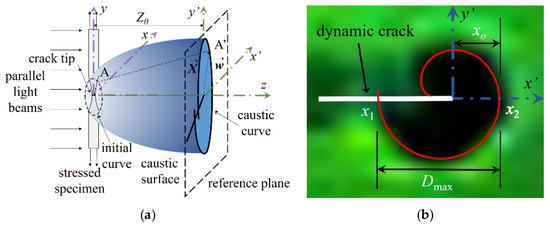
Figure 1.
Formation of caustic images: (a) mode-I caustic spot; (b) mixed mode I-II caustic spot.
Based on the geometric relation of light deflection in Figure 1, the relation between the point A(x,y) on the specimen and the point A’(x’,y’) on the reference plane can be expressed as [19]:
where is the deviation vector and can be determined as follows:
where Z0 is the distance between the specimen and the reference plane; is the change of the optical path length, which can be given as:
Here, n0 is the initial refractive index of the specimen; na is the refractive index of the atmosphere, and is equal to 1; d is the thickness of the specimen for a transparent plate; ∆d is the change in thickness of the specimen under blast load; and ∆ni is the change in the refractive index of the specimen related to the principal stress. For a plate in plane stress condition, ∆ni can be expressed as:
where A and B are the material constants and are equal to 0.53 × 10⁻¹⁰ m2/N and −0.57 × 10⁻¹⁰ m2/N, respectively, for polymethyl methacrylate (PMMA) plate. σ1 and σ2 are the maximum and minimum principal stress, respectively.
According to the caustic theory, the mapping equations of the caustic curve on the reference plane can be expressed as:
where r0 is the initial curve on the specimen, that forms the caustic curve on the reference plane, and can be determined as:
In Equation (6), c is the stress-optical constant for the material and is equal to 0.85 × 10⁻¹⁰ m2/N for PMMA.
Therefore, the dynamic stress intensity factors and of the crack tip can be expressed as:
where Dmax and Dmin represent the maximum and minimum diameter of the caustic spot along the crack direction, respectively; deff is the thickness of the specimen; µ is the proportional coefficient of the dynamic stress intensity factors, which can be determined by the diameter parameters of the caustics spot; g is the numerical coefficient of the stress intensity factors. F(V) is the adjustment factor of crack velocity. For the practical condition, the value of F(V) is approximately equal to 1 when the crack velocity is lower than 0.6CR (CR is the Rayleigh wave speed of the material).
In addition, the crack length can be obtained according to the position of the crack tip. If we set the origin of the Cartesian coordinate system at the crack tip, as shown in Figure 1b, the distance between the crack tip and the front edge of the caustic curve can be calculated based on Dmax, which can be expressed as:
where x1 and x2 are the coordinates of the point on caustic curve respect to the yc’ equal to zero.
From Equation (8), the position of the crack tip can be obtained, then the crack velocity can be calculated based on the increase of crack length at each time interval.
3. Experimental Procedures
3.1. Digital Dynamic Caustic System
The digital laser dynamic caustic experimental system is utilized in our experiment to study the blast-induced crack propagation behavior in rock containging unfilled joint. The sketch map of the experimental setup is shown in Figure 2. The green laser light source (LWGL200 mW) is adopted in our experiment because it is the light that the high-speed camera is most sensitive to. The output power of this laser light source can be adjusted from 0 up to 200 mw, which is suitable for most dynamic caustic tests. The expand device is used to change the laser light into a divergent laser light, which becomes to be a parallel light through the convex lens-I. The convex lens-II is used to direct the light into the high-speed camera, which records the caustic spot on the reference plane. The reference plane is set at a distance of 90 mm away from the specimen in our experiment. A signal control device is used to release the trigger signals to synchronize the charge detonation and the camera recording. In addition, the high speed camera (Fastcam-SA5, Japan) with the frame rate of 100000 fps is adopted to record the fracturing process, and the exposure time of the high-speed camera is set as 369 ns in order to obtain a clear caustic spot during the dynamic events.
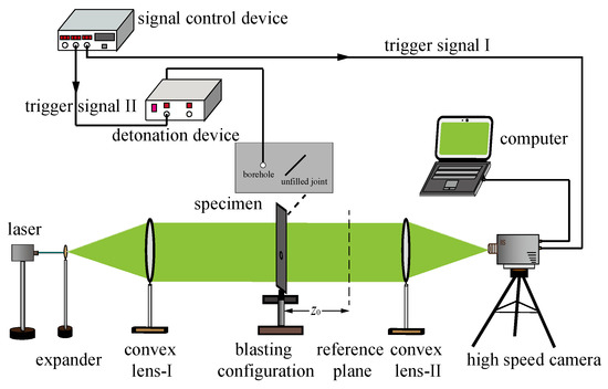
Figure 2.
Digital laser dynamic caustic experimental system.
3.2. Specimen Preparation
As the polymethyl methacrylate (PMMA) is of remarkable optical isotropy and a high optical stress constant, which only produces single caustic curve [19], the PMMA plate is widely used in caustic tests. Moreover, many researchers [24,25,26] have carried out a series of studies to investigate the rock failure mechanism under blast loading using a PMMA plate and have proven that the fracture patterns in PMMA is practically identical with those in rock mass under blast loading, and only the scale, i.e., the length of the crack, differed. In addition, based on the theoretical analysis of the caustic curve, it can be seen that the calculation of dynamic stress intensity factors based on the caustic spot is only valid under a plane stress condition. Therefore, the thickness of the specimen should be thin enough to avoid the three-dimensional effect of the specimen. Furthermore, to minimize the influence of the reflected blast wave from the boundaries of the specimen on the propagation of blast-induced crack, the size of the specimen should be choosed carefully to eliminate the scale effect of the physical model. Through several trails, similar to the caustic experiment done by other researchers [23,24,27], a thin PMMA plate with the dimensions of 400 × 300 × 5 mm3 is adopted to fabricate the specimen as shown in Figure 3. The borehole is located at the center of the specimen with a diameter of 8 mm. To simulate the unfilled joint, a precrack, 50 mm in length, is located at a distance of 60 mm from the center of the borehole. The inclined angle of the specimen is set as 45° and 90°, respectively. The dynamic mechanical parameters of PMMA are as follows [28]: the elastic modulus is 6.1 GPa, Poisson’s ratio is 0.31, the stress-optical constant is 0.80 × 10⁻¹⁰ m2/N, and the speed of the dilatational wave and shear wave is 2320 m/s and 1260 m/s, respectively.
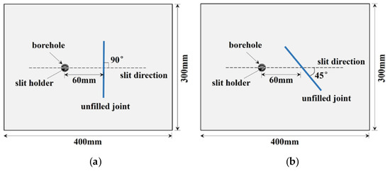
Figure 3.
Schematic diagram of the experimental model: (a) specimen with a vertical joint; (b) specimen with an oblique joint.
In addition, to quantitatively analyze the influence of the unfilled joint on crack propagation, a slit holder is placed in the borehole to create a directional propagated crack. The outer and inner diameters of the slit holder are 8 and 6 mm, respectively. The width of the slit is 0.8 mm. The lead azide (PbN6) with 100 mg was loaded in the slit holder to create a blast loading. The PbN6 was detonated by two twisted copper wires, which could produce a spark once the high-voltage energy released through the copper wire in a short time.
3.3. Experimental Results
3.3.1. Crack Propagation Characteristics
Figure 4 shows the evolution of a caustic spot in the medium containing a vertical joint under blast loading. Due to the high stress gradient at the blast wave front, series of ring-shaped fringes were generated from the borehole after the detonation of slit charge, as can be seen in Figure 4b. When the blast wave encountered the vertical joint at the time of 20 µs, a significant pseudo-caustic spot was formed at the surface of the joint, whereas no obvious stress concentration was generated at the end of the joint. This indicated that the impinging of the dilatational wave is not conductive to the wing crack propagation. At the same time, the reflected wave was generated and propagated towards the borehole. Then, at the time of 40 µs, the reflected wave began to interact with the blast-induced crack, lead to a significant shape distortion of the caustic spot, and further altered the crack propagation behavior. Afterwards, the caustic spot became smaller when the crack propagated near the vertical joint, and the blast-induced crack arrested when the crack encountered the vertical joint. Shortly, an obvious caustic spot began to increase at both ends of the vertical joint, and the wing cracks initiated when the caustic spot reached its critical value. In addition, the propagation direction of the wing cracks at both ends of the vertical joint are basically consistent with the propagation direction of the blast-induced crack.
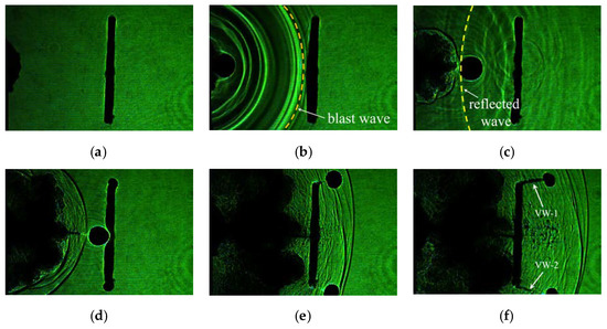
Figure 4.
Evolution of a caustic spot in the medium containing a vertical joint: (a) t = 0 µs; (b) t = 20 µs; (c) t = 50 µs; (d) t = 100 µs; (e) t = 180 µs; (f) t = 220 µs.
Figure 5 shows the evolution of a caustic spot in the medium containing an oblique joint with 45°. It can be seen that the propagation behavior of wing crack at the end of oblique joint is quite different than that at the end of the vertical joint. Due to the existence of the oblique joint, the reflected wave propagated obliquely to the crack propagation direction and induced a significant stress concentration at the end of the oblique joint during the interaction between the blast wave and the reflected wave. At the time of 80 µs, the wing crack at the closer end of the oblique joint began to be initiated and propagated toward the borehole due to the influence of the local stress field, which is generated from the tip of the blast-induced crack. Whereas, the win crack at the far end of the oblique joint initiated and continued to be propagated forward after the blast-induced crack connecting with the oblique joint. This implies that the initiation of a wing crack at the far end of the oblique joint is mainly attributed to the instantaneous energy release at the tip of main crack when it coalesces with the vertical joint, whereas the initiation of a wing crack at the closer end of the oblique joint is mainly owing to the interaction between the local stress around the main crack and the oblique joint.
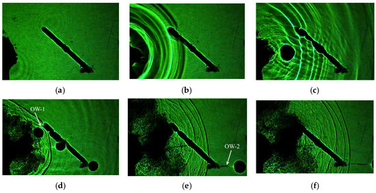
Figure 5.
Evolution of caustic spot in the medium containing oblique joint with 45°: (a) t = 0 µs; (b) t = 20 µs; (c) t = 50 µs; (d) t = 100 µs; (e) t = 160 µs; (f) t = 190 µs.
Compared with the crack propagation behavior in Figure 4 and Figure 5, it can be seen that under the influence of the local stress field around the tip of main crack, the wing cracks at the ends of the oblique joint is more easily to initiate than it at the ends of the vertical joint, because strong stress concentration is formed at the end of the oblique joint. In addition, for the medium with a vertical joint, the size of the caustic spot at the tip of wing crack decreased significantly after being initiated, whereas it changed a little for the oblique joint. This indicates that more energy is consumed in the initiation of the wing crack at the vertical joint than in the oblique joint. Thus, the wing crack at the vertical joint arrested shortly after it initiated. Therefore, for the actual blast engineering, the oblique joint should be escaped in order to obtain a desired contour of the roadways. While the distance between boreholes should be shortened in the medium containing vertical joint.
3.3.2. The Influence of Reflected Wave on a Caustic Spot
Figure 6 and Figure 7 exhibit the variation of a caustic spot when the reflected wave reached the blast-induced crack. Before the reflected wave impinged onto the dynamic crack, a circular caustic is formed at the crack tip, which indicates that the propagation of the blast-induced crack is mainly at mode I type. However, when the reflected dilatational wave, as shown as a bright fringe in Figure 6b, oppositely impinged onto the tip of the blast-induced crack, the caustic spot become ellipsoid, which the vertical length of the caustic spot become shorter, and resulted in a decrease in crack velocity. Whereas, due to the amplitude attenuation of the blast wave, the shear wave cannot be visualized directly in the caustic images, but the time for the incidence of shear wave can be derived through the wave speed. At the time of 90 µs, the shear wave impinged onto the crack tip and the caustic spot changed from mode I type to mixed mode I-II type, indicating that a mixed mode I-II crack failure is generated under the incidence of the shear wave and induces the crack deflected from its original direction.
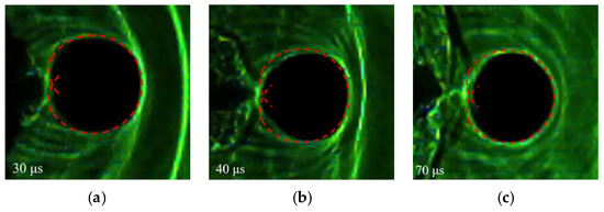
Figure 6.
Specimen with a vertical unfilled joint: (a) without wave incidence; (b) opposite incidence of a dilatational wave; (c) opposite incidence of a shear wave.
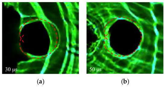
Figure 7.
Specimen with oblique unfilled joint: (a) oblique incidence of a dilatational wave; (b) oblique incidence of a shear wave.
Compared with the opposite incident reflected wave in the medium with a vertical unfilled joint, the caustic spot is severely distorted by the obliquely incidence of the reflected dilatational wave, as shown in Figure 7a. This further implies that the stress concentration is strictly suppressed by the reflected dilatational wave when it obliquely impinged onto the crack tip. Moreover, the size of the caustic spot reduced significantly in both the vertical and transverse length for the oblique incidence of shear wave.
3.3.3. Experimental Results Verification
To verify the identification of the influence of the reflected blast wave on a blast-induced crack, theoretical analyses considering the specimen configuration and the wave speed in PMMA are carried out. The sketches of the reflected blast wave propagation path at the joint are shown in Figure 8.
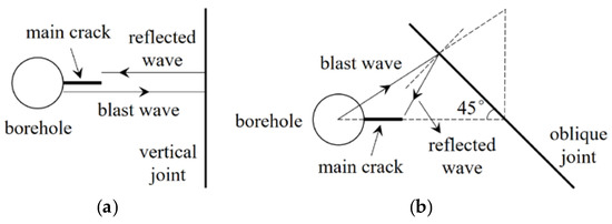
Figure 8.
Sketch of reflected blast wave propagation path at the joint: (a) reflected wave created at the vertical joint; (b) reflected wave created at the oblique joint.
Based on the geometrical relations, for the medium with a vertical unfilled joint, the time for the reflected blast waves encountered the blast-induced crack tip can be calculated through the following equation:
And for the medium containing an oblique unfilled joint with 45°, the time for the reflected blast waves encountered the blast-induced crack tip can be obtained using the following equation:
where tp and ts are the arrival time for the reflected dilatational wave and shear wave encountered the dynamic crack, respectively. d1 is the distance between borehole and the middle point of the unfilled joint; the Lp(t) and Ls(t) are the length of the main crack when it encountered the reflected dilatational and shear wave, respectively; Cp and Ci are the dilatational and shear wave speed of the PMMA, respectively.
Table 1 shows the comparison of the arrival time for the reflected waves encountered the blast-induced crack between the theoretical and experimental results. The errors of arrival time for the reflected waves between the theoretical and experimental analysis are less than 3 µs, indicating that the above identification of a reflected dilatational wave and a reflected shear wave using caustic images are reasonable. The errors between the theoretical and experimental results are partly induced by the calculation of the main crack and are partly due to the recording rate of the high-speed camera.

Table 1.
Comparison of the arrival time for the reflected waves encountered the blast-induced crack between the theoretical analysis and experimental study.
3.3.4. Main Crack Propagation Behavior
Figure 9 presents the velocity of blast-induced main crack versus with time. The VM and OM represent the blast-induced main crack in the specimen with a vertical and oblique unfilled joint, respectively. After the time of 40 μs, the velocity of the main crack VM decreased significantly during the passage of reflected dilatational wave, and then remained stable with approximately 417 m/s when the shear wave impinged onto the propagating crack. Similar to the main crack VM, the velocity of the main crack OM also decreased from 515 to 428 m/s during the incidence of reflected dilitational wave, and then dropped gradually from 428 to 398 m/s. This indicates that the reflected dilitational wave could significantly decrease the opposite propagating crack velocity when it obliquely impinged onto the main crack, whereas the reflected shear wave can slow down the decline rate of the main crack velocity. After the time of 80 μs, the velocity of the main crack for both VM and OM dropped rapidly when the main crack propagated adjacent to the unfilled joint.
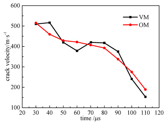
Figure 9.
Main crack velocity versus with time.
Figure 10 illustrates the variation of the dynamic stress intensity factors of the main crack. Compared with the crack velocity, the dynamic stress intensity factor of crack VM dropped a little during the passage of reflected dilatational wave. However, during the incidence of the reflected shear wave, decreased and increased. This indicates that a mixed mode I-II fracturing is produced under the influence of the reflected shear wave. In addition, when the reflected wave obliquely impinged onto the main crack, the value of decreased, and increased. This implies that the propagation of the main crack changed from mode I type to mixed mode I-II type, making an increase in the consumption of fracture energy when the main crack obliquely encountered the reflected wave, and decreased the crack velocity.
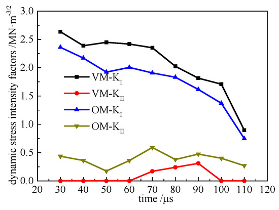
Figure 10.
Dynamic stress intensity factors versus with time.
3.3.5. Wing Crack Propagation Behavior
The evolution of the dynamic stress intensity factors of wing crack and the crack velocity are shown in Figure 11 and Figure 12, respectively. For the medium with a vertical unfilled joint, the value of and increased slowly with the diffraction of the blast waves around the tip of vertical joint. This further verifies that the diffraction of the blast wave at the tip of vertical joint has little influence on the crack propagation. At the time of 120 μs, the main crack VM coalesced with the vertical joint, causing a transient release of elastic energy restored at the tip of the main crack, and then induced significant stress concentration at the tip of the vertical joint, as indicated in the of crack VW-1, which increased suddenly at the time of 150 µs. After that, the wing crack VW-1 initiated abruptly from the end of the vertical unfilled joint. However, after a short while the velocity of wing crack VW-1 decreased rapidly as the dissipation of the blast wave. For the medium containing an oblique unfilled joint, the wing crack OW-2 at the end of the oblique joint initiated much earlier than the wing crack VW-1, as the local stress around the main crack induced more significant stress concentration at the end of the oblique joint. After the main crack OM coalesced with the oblique joint, the elastic energy released instantly from the tip of the main crack. At a same time, the detonation gas rapidly expanded to the wing crack through the oblique joint and further induced the velocity of wing crack OW-2 to increase rapidly from 240 to 350 m/s. This implies that the diffraction of stress wave at the tip of the oblique joint plays an important role on the wing crack OW-2 initiation, while once the main crack connected the oblique joint, it is plausibly believed that the expansion of detonation gas also contributed to the propagation of the wing crack, which is the internal reason for the longer length of the wing crack in the medium containing an oblique unfilled joint.
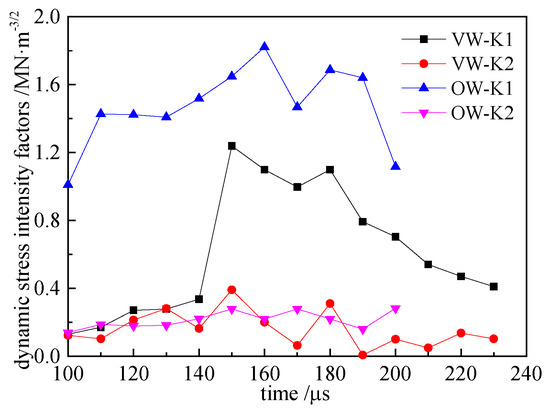
Figure 11.
Dynamic stress intensity factors of wing crack versus with time.
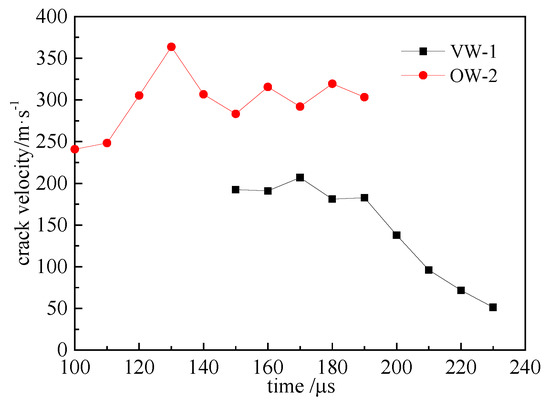
Figure 12.
Wing crack velocity versus with time.
4. Numerical Simulation and Results Analysis
4.1. Numerical Model
To further reveal the mechanical mechanism of the failure pattern in a jointed rock under blasting, a finite element method (FEM) was used to investigate the propagation of a blast wave. Among the pieces of finite element software, ABAQUS has been commonly used to simulate the stress evolution under impact, blast and other dynamic loadings [29,30,31]. Therefore, the ABAQUS software was used to carry out the numerical simulation in our study. The size of the numerical model employed in our study is the same as the physical experiment (Figure 3). The dynamic mechanical properties of PMMA is applied in the numerical model. The model of the specimen was developed in ABAUQS/CAE using the 3D part option and eight node linear brick element (C3D8R) with reduced integration and hourglass control. Figure 13 shows the typical mesh of the model around the borehole and the unfilled joint. The sweep technique with a medial axis algorithm is adopted to generate the mesh element around the borehole, and the structure technique is applied elsewhere. The mesh convergence investigation has been performed and a higher mesh density is used around the borehole and the unfilled joint for achieving higher accuracy. The minimum size of the element around the borehole and the joint is 0.5 mm, and the boundary elements are set as 1.5 mm in size. Similar to the physical model, the free boundary condition is applied. And the dynamic explicit solution procedure is used to calculate the stress evolution in the medium with an unfilled joint under blast loading.
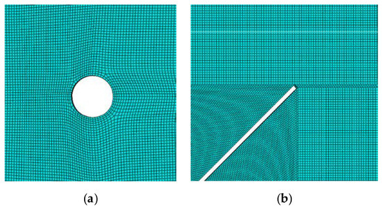
Figure 13.
The typical mesh of the numerical model around the borehole and the unfilled joint: (a) typical mesh around the borehole; (b) typical mesh around the unfilled joint with 45°.
For the blast loading simulation, the Conwep interaction, which has been built in ABAQUS, is applied in our numerical model. The Conwep function is a conventional empirical blast loading function established by the US army engineer. The Conwep interaction is defined as an incident wave interaction with the blast area of test specimen. The properties of the Conwep interaction were defined as an air blast with the equivalent mass of Trinitrotoluene (TNT). In our numerical model, the source point is defined at the center of the borehole. The specific equivalent mass of TNT in our study is 100 mg.
4.2. Numerical Results Analysis
Figure 14 and Figure 15 show the evolution of mises stress in the medium containing the unfilled joint with an angle of 90° and 45°, respectively. It can be seen that the unfilled joint severely obstructed the propagation of blast waves. When the blast wave encountered the joint, a strong reflected wave was generated and altered the stress field between the borehole and the joint, and thus significantly influenced the propagation behavior of the main crack. In addition, the results also show that the stress concentration at the tip of vertical joint attenuated rapidly with the spreading of the diffraction wave, whereas the stress concentration at the far tip of the oblique joint sustained much longer compared with the stress concentration at the end of the vertical joint. This also certified that the wing crack at the far end of the oblique joint may extend much longer than that at the end of the vertical joint.

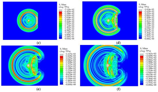
Figure 14.
Medium with a vertical unfilled joint: (a) 10 µs; (b) 20 µs; (c) 30 µs; (d) 40 µs; (e) 50 µs; (f) 60 µs.
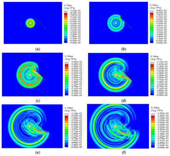
Figure 15.
Medium with oblique unfilled joint: (a) 10 µs; (b) 20 µs; (c) 30 µs; (d) 40 µs; (e) 50 µs; (f) 60 µs.
Figure 16, Figure 17 and Figure 18 show the stress distribution characteristic around the vertical joint for the time of 30 μs, 40 μs and 70 μs, respectively. S11, S22 and S12 represent the normal stress in the x direction, normal stress in the y direction and in-plane shear stress, respectively. It can be seen that when the blast wave arrived the end of the vertical joint at the time of 30 μs, the normal stresses in both the x direction and y direction are negative, which implies that the wing crack is not expected to generate at this time. However, after a while, the normal stresses around the end of the vertical joint become tensile in both the x direction and y direction when a positive sign of blast wave encountered the joint. In addition, the in-plane shear stress become more obvious around the vertical joint compared with the normal stresses at the time of 70 μs. This indicates that the mode II crack failure dominates the initiation of the wing crack at the tip of the vertical joint. This is also coincident with the experiment results, in which the propagation direction of wing crack is almost perpendicular to the vertical joint.
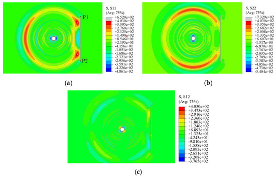
Figure 16.
The stress distribution characteristic around the vertical unfilled joint for the time of 30 μs: (a) S11 (normal stress in the x direction), (b) S22 (normal stress in the y direction), (c) S12 (in-plane shear stress).
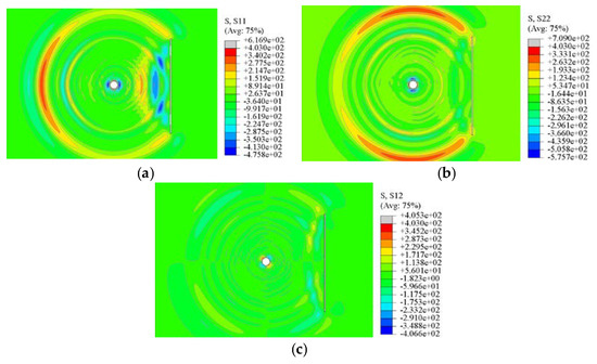
Figure 17.
The stress distribution characteristic around the vertical unfilled joint for the time of 40 μs: (a) S11 (normal stress in the x direction), (b) S22 (normal stress in the y direction), (c) S12 (in-plane shear stress).
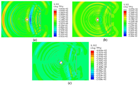
Figure 18.
The stress distribution characteristic around the vertical unfilled joint for the time of 70 µs: (a) S11 (normal stress in the x direction), (b) S22 (normal stress in the y direction), (c) S12 (in-plane shear stress).
Figure 19 and Figure 20 show the stress distribution around the oblique joint for the time of 30 μs and 55 μs, respectively. For the near end of the oblique joint, a significant stress concentration is formed with the diffraction of the blast wave. For the far end of the oblique joint, a significant stress concentration is formed by the superposition between the reflected wave and the blast wave.
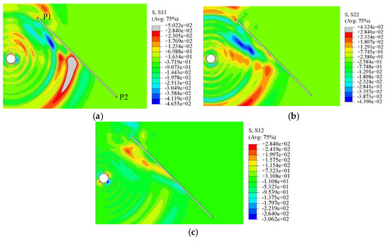
Figure 19.
The stress distribution characteristic around the oblique unfilled joint for the time of 30 μs: (a) S11 (normal stress in the x direction), (b) S22 (normal stress in the y direction), (c) S12 (in-plane shear stress).
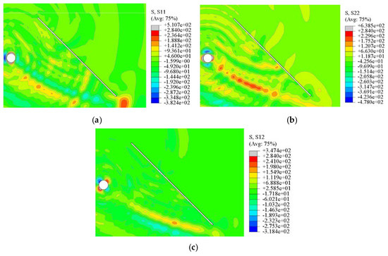
Figure 20.
The stress distribution characteristic around the oblique unfilled joint for the time of 55 μs: (a) S11 (normal stress in the x direction), (b) S22 (normal stress in the y direction), (c) S12 (in-plane shear stress).
The stress evolution at the end of the joint is shown in Figure 21. The points P1 and P2 are located at the top and bottom end of the unfilled joint, respectively, as shown in Figure 16a and Figure 19a. It can be seen that the normal stresses at both end of the vertical joint presented the same variation characteristic, whereas the sign of in-plane shear stress showed an inverse trend with the incidence of the blast wave. This is the reason why the sign of is different for the initiation of wing crack VW-1 and VW-2. Combined with the crack fracture characteristic, it can be concluded that the negative sign of shear stress could induce the wing crack initiated in a clockwise direction, whereas the positive sign of shear stress could induce the wing crack initiated in a counterclockwise direction. In addition, the stresses are much higher at the near end of the oblique joint than that at the far end of the oblique joint. This also well clarified that why the wing crack is more easy to initiate at the near end of the oblique joint.
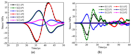
Figure 21.
Stress evolution of the point at the end of the joint: (a) vertical unfilled joint; (b) oblique unfilled joint.
5. Conclusions
In this paper, the dynamic caustic technique, combined with the numerical simulation, is applied to study the crack fracture characteristic in the medium with the unfilled joint. Some important conclusions are summarized as follows:
(1) The reflected wave from the vertical joint tends to suppress the dynamic stress intensity factor of the opposite propagating crack and decreases the crack velocity.
(2) The reflected wave from the oblique joint increases the dynamic stress intensity factor of the opposite propagating crack, which tends to make the crack propagate at the mixed mode I-II fracturing type, and induces crack deflection.
(3) The initiation direction of the wing crack is related to the sign of the in-plane shear stress at the end of the unfilled joint. When the in-plane shear stress is negative, the crack deflects in the clockwise direction, whereas it turns counterclockwise when the in-plane shear stress is positive.
(4) The length of the wing crack at the oblique joint is much larger than that at the vertical joint as a result of the longer stress concentration being generated at the tip of the main crack.
Author Contributions
Writing—original draft preparation and formal analysis, P.X.; Conceptualization, methodology and supervision, R.Y.; investigation and writing—review and editing, Y.G.; data curation, Z.G. All authors have read and agreed to the published version of the manuscript.
Funding
This research was funded by the National Key Research and Development Program (Grant No. 2016YFC0600903), the State Key Program of National Science of China (Grant No. 51934001), China Postdoctoral Science Foundation (Grant No. 2019M650492), and the Science and Technology Support Programme of Sichuan Province (Grant No. 2018JZ0036).
Acknowledgments
The author would like to acknowledge the anonymous reviewers for their valuable and constructive comments.
Conflicts of Interest
The authors declare no conflict of interest.
References
- Goodman, R.E. Methods of Geological Engineering in Discontinuous Rocks; West Information Publishing Group: Eagan, MN, USA, 1976. [Google Scholar]
- Li, J.; Ma, G.; Huang, X. Analysis of Wave Propagation Through a Filled Rock Joint. Rock Mech. Rock Eng. 2010, 43, 789–798. [Google Scholar] [CrossRef]
- Chakraborty, A.K.; Jethwa, J.L.; Paithankar, A.G. Effects of joint orientation and rock mass quality on tunnel blasting. Eng. Geol. 1994, 37, 247–262. [Google Scholar] [CrossRef]
- Li, J.C.; Ma, G.W. Experimental study of stress wave propagation across a filled rock joint. Int. J. Rock Mech. Min. Sci. 2009, 46, 471–478. [Google Scholar] [CrossRef]
- Huang, X.; Qi, Z.; Qi, S.; Xia, K.; Giovanni, G.; Chen, X. Numerical Simulation on Seismic Response of the Filled Joint under High Amplitude Stress Waves Using Finite-Discrete Element Method (FDEM). Materials 2016, 10, 13. [Google Scholar] [CrossRef] [PubMed]
- Huang, X.; Qi, S.; Yao, W.; Xia, K. Effect of Filling Humidity on the Propagation of High-Amplitude Stress Waves through an Artificial Joint. Geotech. Test. J. 2019, 42, 20170192. [Google Scholar] [CrossRef]
- Liu, W.; Yue, Z.W.; Yang, G.L. Experimental investigation of a circumferential crack in a PMMA cylindrical shell using caustics. Polym. Test. 2019, 79, 106086. [Google Scholar] [CrossRef]
- Xu, P.; Yang, R.S.; Guo, Y.; Chen, C.; Zhang, Y.T. Experimental and numerical investigation of the interaction between blast wave and precrack in a defected material. Appl. Opt. 2019, 58, 9718–9727. [Google Scholar]
- Yang, R.S.; Wang, Y.B.; Guo, D.M.; Xue, H.J. Experimental Research of Crack Propagation in Polymethyl Methacrylate Material Containing Flaws Under Explosive Stress Waves. J. Test. Eval. 2016, 44, 248–257. [Google Scholar]
- Yue, Z.W.; Yang, R.S.; Ma, X.M.; Guo, D.M. Experimental study on crack coalescence mechanisms of pre-existing flaws under blast loading. Proc. SPIE Int. Soc. Opt. Eng. 2008, 7375, 73751C-7. [Google Scholar]
- Shen, S.; Liao, W.; Xu, Y.; Li, D. Dynamic caustics test of rock mass under different joint spacing conditions with two-hole blasting. J. China Coal Soc. 2018, 43, 2180–2186. [Google Scholar]
- Gu, J.; Zhao, Z. Considerations of the discontinuous deformation analysis on wave propagation. Int. J. Numer. Anal. Methods Geomech. 2009, 33, 1449–1465. [Google Scholar] [CrossRef]
- Zhu, J.B.; Zhao, G.F.; Zhao, X.B.; Zhao, J. Validation study of the distinct lattice spring model (DLSM) on P-wave propagation across multiple parallel joints. Comput. Geotech. 2011, 38, 298–304. [Google Scholar] [CrossRef]
- Zhao, J.; Cai, J.G.; Zhao, X.B.; Li, H.B. Dynamic Model of Fracture Normal Behaviour and Application to Prediction of Stress Wave Attenuation across Fractures. Rock Mech. Rock Eng. 2008, 41, 671–693. [Google Scholar] [CrossRef]
- Liu, C.; Yang, M.; Han, H.; Yue, W. Numerical simulation of fracture characteristics of jointed rock masses under blasting load. Eng. Comput. 2019, 36, 1835–1851. [Google Scholar] [CrossRef]
- Wang, Z.L.; Konietzky, H. Modelling of blast-induced fractures in jointed rock masses. Eng. Fract. Mech. 2009, 76, 1945–1955. [Google Scholar] [CrossRef]
- Manogg, P. Anwendung der Schattenoptik zur Untersuchung des Zerreissvorganges von Platten. Ph.D. Thesis, West Germany Freiburg University, Freiburg, Germany, 1964. [Google Scholar]
- Theocaris, P.S.; Katsamanis, P. Response of cracks to impact by caustics. Eng. Fract. Mech. 1978, 10, 197–210. [Google Scholar] [CrossRef]
- Kalthoff, J.F. The Shadow Optical Method of Caustics. In Static and Dynamic Photoslasticity and Caustics; Lagarde, A., Ed.; Springer: New York, NY, USA, 1986; pp. 407–522. [Google Scholar]
- Rosakis, A.J.; Duffy, J.; Freund, L.B. The determination of dynamic fracture toughness of AISI 4340 steel by the shadow spot method. J. Mech. Phys. Solids 1984, 32, 443–460. [Google Scholar] [CrossRef]
- Li, Q.; Zhao, Y.P.; Ma, Y.L.; Wang, D.X.; Yang, R.S. Application of dynamic caustics for cracks propagation under blasting load. Eng. Blast. 2005, 11, 9–12. [Google Scholar]
- Yang, L.Y.; Yang, R.S.; Xu, P. Caustics method combined with laser & digital high-speed camera and its applications. J. China Univ. Min. Technol. 2013, 42, 188–194. [Google Scholar]
- Qiu, P.; Yue, Z.; Yang, R.; Li, J.C. Effects of vertical and horizontal reflected blast stress waves on running cracks by caustics method. Eng. Fract. Mech. 2019, 212, 164–179. [Google Scholar] [CrossRef]
- Wang, Y. The Rock-Breaking Mechanism of Directional Fracture Blast Using an Irregular Shape Cartridge and Its Field Application. J. Test. Eval. 2019, 47, 1551–1568. [Google Scholar] [CrossRef]
- Meng, L.; Zhu, Z.M.; Liu, R.; Bang, L.; Dong, Y. Study of the Effect of Empty Holes on Propagating Cracks under Blasting Loads. Int. J. Rock Mech. Min. Sci. 2018, 103, 186–194. [Google Scholar]
- Nakamura, Y.; Cho, S.H.; Yoneoka, M.; Yamamoto, M.; Kaneko, K. Model experiments on crack propagation between two charge holes in blasting. Sci. Technol. Energetic Mater. 2004, 65, 34–39. [Google Scholar]
- Yue, Z.W.; Yang, L.Y.; WANG, Y.B. Experimental study of crack propagation in polymethyl methacrylate material with double holes under the directional controlled blasting. Fatigue Fract. Eng. Mater. Struct. 2013, 36, 827–833. [Google Scholar] [CrossRef]
- Yang, R.S.; Xu, P.; Yue, Z.W.; Chen, C. Dynamic fracture analysis of crack–defect interaction for mode I running crack using digital dynamic caustics method. Eng. Fract. Mech. 2016, 161, 63–75. [Google Scholar] [CrossRef]
- Tiwari, R.; Chakraborty, T.; Matsagar, V. Dynamic Analysis of Twin Tunnel Subjected to Internal Blast Loading. Indian Geotech. J. 2015, 56, 1–12. [Google Scholar]
- Longere, P.; Geffroy-Greze, A.-G.; Leble, B.; Dragon, A. Ship structure steel plate failure under near-field air-blast loading: Numerical simulations vs experiment. Int. J. Impact Eng. 2013, 62, 88–98. [Google Scholar] [CrossRef]
- Lu, J.F.; Zhuang, Z.; Shimamura, K.; Shibue, T. Application of Numerical Simulation to SHPB Test to Investigate the Dynamic Compressive Behavior of Material with Failure. Key Eng. Mater. 2003, 243–244, 433–438. [Google Scholar] [CrossRef]
© 2020 by the authors. Licensee MDPI, Basel, Switzerland. This article is an open access article distributed under the terms and conditions of the Creative Commons Attribution (CC BY) license (http://creativecommons.org/licenses/by/4.0/).