1. Introduction
The US National BIM Standard (NBIMS-US) defines BIM as “a digital representation of physical and functional characteristics of a facility” [
1]. In other words, building information modeling (abbreviated and commonly called “BIM”) is a virtual platform where graphical and nongraphical data are produced, visualized, processed, analyzed, exchanged, shared, and maintained in the architecture, engineering, and construction (AEC) industry. The approach on which BIM is based is that before physically building the structure, it is built in a virtual system as a “digital twin” of the physical structure itself. In this way, problems can be anticipated, simulated, and worked out before the execution phase [
2]. BIM is not only a software platform used for modeling a structure but also a process and approach that allows us to follow the design of the project and the life cycle of the structure in a virtual environment in a comprehensive way from the beginning of the concept.
Recently, construction industry technology has started to evolve from conventional 2D methods to 3D platforms by the commercial use of BIM tools. The increase in demand, initiatives, and collaboration of different disciplines in the AEC industry and the adoption of BIM platforms for design entails transferring data between different users from a variety of trades that have started to exploit BIM platforms. In 2018, research from China [
3] revealed how BIM tools are used by different disciplines in the AEC industry. These tools are most frequently used at the design stage for model design (25.9%) and model checking (24.8%), respectively. These are followed by quantity take-off (16.3%), construction simulation (13.8%), construction management (7.6%), and visualization and roam (6.2%). The tools are less frequently used for terrain (2.1%) and prefabrication (2.3%). Only a small number of the projects used the tools for preservation (0.5%), operation and maintenance (0.5%), and refurbishment (0.2%). A more recent paper [
4] presented the results of a similar investigation, referring to the use of BIMs for educational facility projects in the United States. Considering five categories of stakeholders like architects, contractors, structural, site, and MEP (Mechanical, Electrical and Plumbing) engineers, the major BIM applications were 3D visualizations, automation of documentation, and clash detection. Depending on the discipline’s scope of work, the architects and site engineers thought that the use of BIM was providing value in the design phase of the project while the structural engineers and contractors saw the benefits of BIM use in both design and construction phases of the projects. MEP engineers thought that BIM use was almost equally valuable in all the project phases. In [
5], a more general and global investigation on the status of BIM adoption worldwide is presented.
Since there are many different disciplines involved in this industry, BIM-based tools are implemented and used to perform a large variety of tasks, i.e., creating 3D geometry of buildings, structural analysis, cost estimation and planning, and operating the facility [
6]. Generally, working with different disciplines also means working with different types of software packages and file formats and extensions. Today, there are several exchange formats frequently used in the AEC industry, such as DXF, DWG, XML, SAT, STP, 3Ds, and IFC or CIS/2 [
7]. Moreover, there is no single software able to perform all these tasks; hence, the use of more than one single software is a must. Software packages in the market do not support or have limited support for exchanging data. Thus, when performing analyses requiring the transfer of data from one tool to another, due to the incompatibilities in file exchange, an additional effort is generally required. In addition to this, also throughout the exchange operations, the different file format versions must be taken into account, even if the file standards are the same. This is due to the fact that new updates in versions may cause conflicts. To solve these problems, while addressing the exchange operations, it is necessary to describe the term “interoperability”. The Institute of Electrical and Electronics Engineers (IEEE) defines it as “the ability of two or more systems or components to exchange information and to use the information that has been exchanged” [
8]. For a smooth workflow, “interoperability” is vital due to the properties of preventing recreation or reinput of data and facilitating the efficient use of information through workflow collaboration [
9].
Focusing on BIM systems, there have been significant attempts to develop standards to set interoperability between such systems to make them compatible with each other. This means that for a model to be compatible with models created by other software tools, it is crucial for all of them to be translatable into a file format so that all the information of the objects can be properly transferred [
10]. In general, the issues related to interoperability in BIM projects are mostly solved with a standardized file exchange format, i.e., Industry Foundation Classes (IFC), which was first specified in 1996 by the International Association for Interoperability (IAI) and developed by buildingSMART International [
11]. As it is described in the website of buildingSMART, the definition of IFC is “In general, IFC, or ‘Industry Foundation Classes’, is a standardized, digital description of the built environment, including buildings and civil infrastructure. It is an open, international standard (ISO 16739-1:2018) meant to be vendor-neutral, or agnostic, and usable across a wide range of hardware devices, software platforms, and interfaces for many different use cases” [
12]. IFC indicates “how” information is to be exchanged. It is one of the public and worldwide accepted standards (ISO/PAS 16739:2005) for the exchange of information in the AEC industry [
11]. IFC adopts the ISO-STEP EXPRESS language to describe its models. Objects defined in the IFC data model allow the sharing of “intelligent” information included in BIM [
10].
As clarified, interoperability and BIM are strictly related to each other, and the research community has been paying much attention to this relationship from several points of view. For instance, the authors in [
13] presented the Rosewood experiment, where product data exchange in the design and fabrication of architectural precast façades in a BIM environment was examined. Results showed that the data exchanges between architectural and precast engineering systems were incomplete and inconsistent, confirming the need for BIM exchange standards improvements. Improvements could be applied not only to standards but also to their use. An example can be found in [
14], where the authors proposed a data-driven, iterative method that could be used to develop an algorithm to automatically classify each object in an IFC model into predefined categories to avoid misuses of IFC entities during the creation of BIM models. In the field of the construction industry, interoperability analyses were also conducted in the framework of system performance assessments and energy analysis due to the clear involvement of different disciplines. Other authors have proposed an interoperability specification development approach for performance-based design [
15], aimed to improve the building design process by developing a method to determine the interoperability of the utilized programs for evaluating a building's energy performance and indoor comfort [
16], and described potential challenges and opportunities for using thermal simulation tools to optimize building performance [
17]. In this paper, the workflow of the data exchange of multiple thermal analyses for BIM-based applications is presented. More practically, Moon et al. [
18] studied the interoperability between a BIM-based architectural model and several performance analysis programs based on the gbXML protocol.
However, interoperability has been investigated not only from the technological point of view. In fact, Abd Jamil and Fathi [
19] investigated the implications of enhancing information interoperability by assessing BIM-based contractual issues such as technology compatibility, auditing procedures and responsibilities, and information and communication technology (ICT) protocols, processes, and transfer procedures. Another study suggested that seeking solution(s) to the interoperability problem should include an analysis of an interoperability value proposition in the AEC sector, i.e., at the business level [
20]. In [
21], the authors systematically and critically reviewed BIM compatibility literature to distinguish compatibility issues at the organizational level and the concept of interoperability at the technical level. In [
22], an exploratory research approach explored the interoperability between the construction design and management (CDM) regulations and BIM.
On the other hand, the integration of BIM with other technologies like augmented reality for quality control during the construction phase also shows the importance of compatibility between several platforms where the use of IFC standards is crucial [
23]. Another research field where interoperability is fundamental is the integration of BIM with geospatial data. Currently, building and geospatial data are shared and exchanged through common data formats, usually IFC and CityGML. Because of the diversity and complexity of domain knowledge across BIM and geographic information system (GIS) systems, these syntactic approaches are not capable of completely sharing semantic information that is unique in each system. In [
24,
25], semantic web technology was used to ensure semantic interoperability between existing BIM and GIS tools. In [
26], the study aimed at improving the interoperability between BIM and GIS application domains by linking and harmonizing core information concepts by investigating the integration between core abstract concepts from IFC and ISO/TC 211 standards for GIS.
Research topics in the field of BIM and interoperability are broad, and many questions still arise. In [
27], the authors investigated the interoperability research gaps and trends in BIM for architecture, engineering, construction, operation, and facility management (AECO/FM). In [
28], the authors reviewed the practical context in which interoperability issues are raised in the literature. More precisely, they addressed questions such as what is exactly expected from a given BIM data exchange and what interoperability is needed for. The success of interoperability between two different systems can be assessed by the following criteria: (a) the execution of the export and import translator functions inserted in BIM tools, (b) the internal structure of the neutral file format supported by the BIM tools, and (c) the variety of data object types to be shared.
Following these criteria, this study aims at investigating the degree of interoperability between software platforms that are commonly used for design and project management in the AEC industry. The goal is not to judge a single software to decide if a specific one is better than another (this would be totally out of the scope of the research) but to provide practical information to users facing similar problems in the real world. Although the investigation is carried out with simple data exchanges between software packages, the authors have decided to investigate both directions of importing/exporting data. Such data refer not only to geometric information but also to thematic information that is critical for project management purposes. In literature, this approach has been found to be common for assessing the interoperability between different software packages, but, although it is a common practice, no examples targeting project management tasks have been found.
2. Materials and Methods
For this study, interoperability analyses were performed by choosing different software packages that are commonly used in the AEC industry to simulate real-life engineering problems throughout various file exchange operations. The important point in an exchange operation between different software packages is that even if they are used for achieving similar tasks and include analogous functions, they may offer various ways to define an object or a task. This means elements created in one BIM software may not be successfully exchanged with another BIM software with full functionality and complete data. If one considers how the design and construction works are carried out, it is understandable that during the exchange of files, any data loss, including material type, scheduling or phasing information, cost of elements, or 3D data related to fabrication and production, can be followed by loss of quality, ineffective teamwork, cost overruns, and time delays.
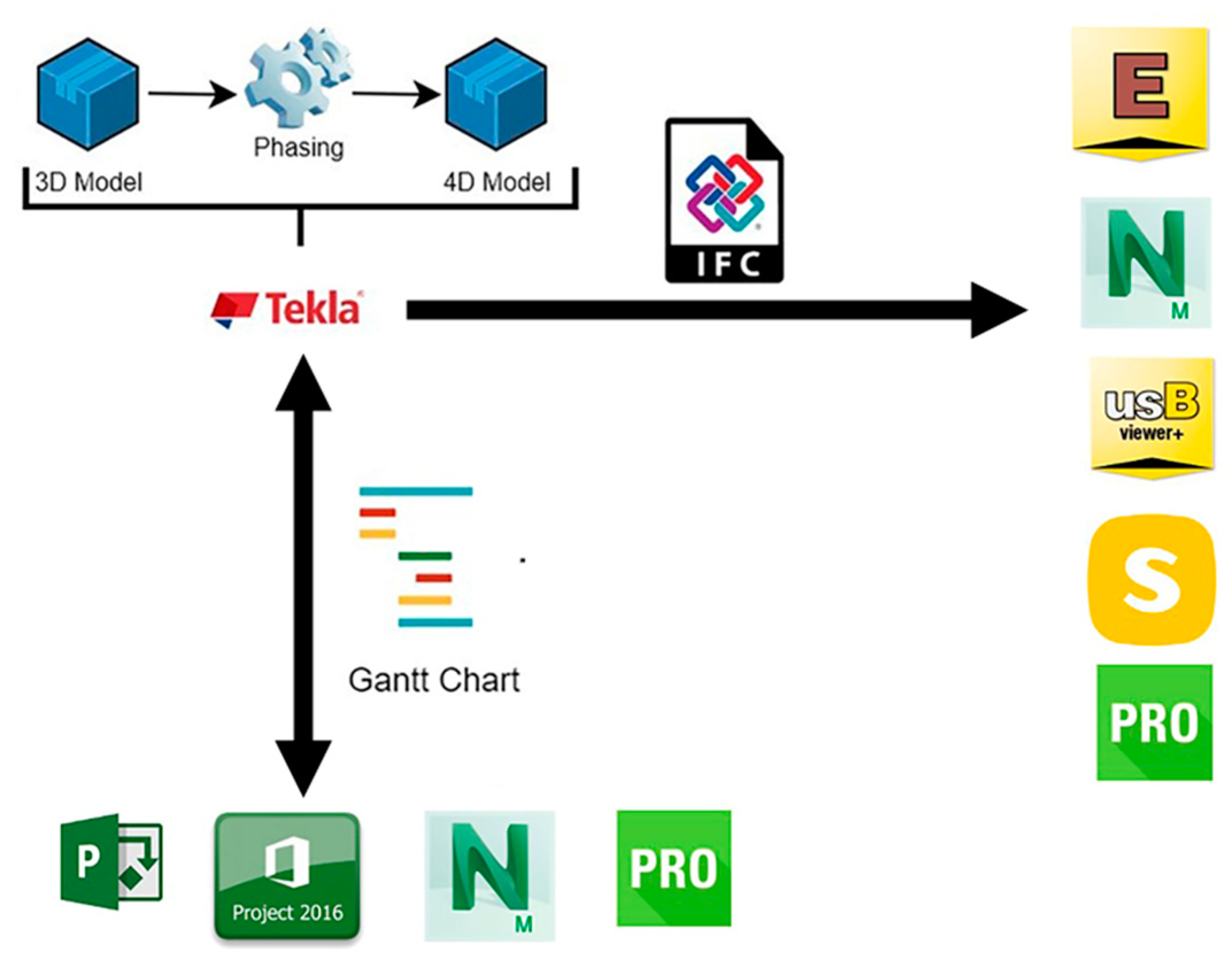
For the coherent representation of workflow between model designers and construction project managers or planning engineers, the used software packages have been divided into three groups according to their features (
Figure 1).
Design software: software packages generally used for designing and developing a BIM model, like Tekla Structures® (2018i service pack 1, Trimble®, CA, United States) and Edificius® (BIM One (e) – 12.0.4.20368, ACCA®, Italy). In general, both are commonly used to design, associate, manage, and collaborate in a 3D environment for different tasks. They can be used from the very beginning of the project by directing design, fabrication, construction, and detailing processes to the end of the service life of the structure by providing additional information for maintenance for different users from different professions.
IFC viewers: software packages usually used for model display and checking and reviewing semantic data embedded in BIM models exploiting the IFC standard. In this study, usBIM.viewer+® (BIM 2(a), ACCA®, Italy) and Solibri Model Checker® (9.10.6.23, Graphisoft®, Hungary) were chosen.
Construction project management software (CPM): software packages that include the tools used mostly in construction project management and reviewing models. In practice, these software packages are used, e.g., by project managers, consultants and planning engineers, and suppliers. Among them, Navisworks® 2019,(16.0.1326.55, Autodesk® , CA, United States), Synchro Pro® 2019 (6.2.1.3, Bentley®, PA, United States) have similar functions, like 4D scheduling and construction project management, plus the capability of reading and checking IFC models. Another software package used in this study was Project® (Microsoft®, WA, United States), a useful tool to manage projects in terms of schedules. In fact, this software is very handy for construction project management tasks through creating, processing, and exchanging Gantt Charts. In this research, both MS Project 2013 (KB2817433) and MS Project 2016 (KB3115284) versions were used.
Since, in this research, the exchange operations of produced IFC files between various BIM packages are examined, it is useful to point out that the IFC data format is supported by most software packages. In particular, BuildingSMART provides certification for the tools in the BIM industry to validate the use of IFC. Tekla Structures, Edificius, usBIM.viewer+ and Solibri Model Checker are IFC 2x3 certified [
29]. Furthermore, another interoperability analysis was also performed based on importing/exporting different Gantt Charts in each software, and the quality of the exchanged data was assessed. In this process, the exchange of Gantt Charts between these packages was performed in XML or CSV format, depending on the software capabilities.
For the purposes of this research, three different types of simulations were carried out. The first one is aimed at checking BIM interoperability through IFC standards and is performed by investigating if 3D and 4D information can be correctly transferred via IFC files. A sample 3D model was built in Tekla Structures, the construction sequence of each structural element was defined to obtain a 4D model, and the sample model was exported/imported through IFC from Tekla Structures to the other packages (Edificius, Navisworks, Synchro Pro, usBIM.viewer+, and Solibri Model Checker) to be tested in order to detect missing or conflicting schematic/metadata information.
The second simulation test (BIM Interoperability through Gantt Charts – Design2Management) regards the assessment of Gantt Chart exchanges produced by Tekla Structures and imported to CPM software packages. According to the schema where the modeled structure in Tekla Structures is divided into different tasks by assigning a generic duration to each of them (start and end dates), the corresponding Gantt Chart was transferred through XML format to the CPM software packages.
The third simulation test (BIM Interoperability through Gantt Charts – Management2Design) can be considered as the reverse of the second experiment. Sample Gantt Charts were created in each CPM software and exported via XML to Tekla Structures. A summary workflow of the experiments is provided in
Figure 2.
For each test, the goal is to investigate the following issues: how much data can be exchanged from one tool to another; the possibility of exchanging a 4D BIM model between various BIM software packages by using only IFC, without loss of detail or data conflicts; the quality and processability of the transferred data; the presence of changes in the Gantt charts after export and import operations; the level of adverse effects of lost data for the collaborators.
The sample BIM model to be used as a starting point and reference for the subsequent analysis was created with Tekla Structures. The modeled structure is a building with three upper floors with a flat roof and one basement at 2.60 m depth. The height and length of the building are 9.10 and 19.00 m, respectively. The quantity, dimensions, shape, material type, location, and orientation of the elements were included in the model, along with some structural element details such as the stairs, also including the steel one where the bolts, bolt types, and welds were clearly defined.
Figure 3 shows the sample model.
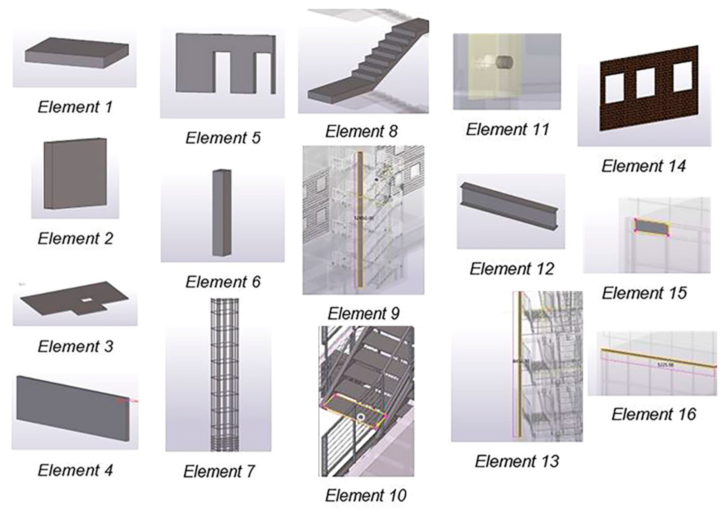
To obtain a 4D model, phases were assigned to each representative element. The selected elements are shown in
Figure 4. Phasing names were chosen according to the relevant tasks, which were supposed to be performed in a sequential way. Based on such phasing, the most relevant information needed to create a Gantt chart were defined. In particular, the fields “Task Names” were defined according to the designed elements; additionally, both “Start Date” and “End Date” were defined in a generic way but according to the previously defined phasing. Once all the relevant features of the sample model were in place, in order to perform the interoperability tests, the sample model was exported in IFC format, with IFC2x3 import and export certificates being granted [
30]. Among the available Model View Definitions, the Coordination View 2.0 option was chosen, since it is focused on the coordination of architectural, structural engineering, and building services tasks in the design phase. The corresponding Gantt chart was exported in XML format. The result is shown in
Figure 5.
3. Results
For the assessment of IFC interoperability, a subset of data present in the reference model was chosen, namely, “Name”, “Geometrical Properties”, “Material Type”, and “Phase Number”. To emphasize the significance of the chosen data, they are the most exploited ones in 4D BIM models and construction management tasks. “Name” is obviously crucial because after completing the data exchange, the defined name for a specific element must be properly shown in the receiving software package; otherwise, inconsistencies will occur. “Geometrical Properties” is also fundamental when assessing the geometry and shape of the 3D element. Inaccuracies appearing at this stage may lead to wrong or inadequate interpretation of the 3D model. “Material Type” carries information about the construction duration of the specific element, depending on the construction material. It is necessary to obtain the correct information of “Material Type” in a 4D BIM after completing the IFC exchange. “Phase Number” identifies the construction sequence phase of the specific element. It contains “time” data, which is fundamental information for 4D BIM in scheduling, planning, and managing construction activities.
Once the IFC model was imported, for each phased element, an assessment was performed based on the following scale:
Good interoperability: the exported parameter is successfully transferred and correctly received by the BIM software importing it.
Medium interoperability: the exported parameter is transferred but not correctly received by the BIM software importing it; some details may have been lost; however, the imported information can still be used and is meaningful.
Poor interoperability: the exported parameter is transferred but not in the form it was in in the original BIM software; the parameter has changed and could be misleading.
No data found: the exported parameter is not found in the BIM software importing it.
The same scale was also used in the interoperability analysis based on the exchange of Gantt charts, evaluating the reliability of the fields “Task Names”, “Start Date”, “End Date”, and “Task Duration”.
3.1. BIM Interoperability Through IFC Standard
In this subsection, the assessment of the exchanged IFC model between Trimble Tekla Structures and ACCA Edificius, Autodesk Navisworks, Synchro Pro, ACCA usBIM.viewer+, and Graphisoft Solibri Model Checker is presented. The evaluation was performed by checking all the 16 repetitive elements and corresponding chosen parameters in the importing software.
ACCA Edificius correctly imported all the names of the elements, identifying them in the description tab as IfcEntity “Input Name” (Dimensions). For example, for Element 1, its description was decoded as IfcSlab “SLAB” (300*2100). From this point of view, the information was properly transferred (overall, good interoperability). In terms of representation and geometrical properties, two elements showed defects. In Element 7, there were some missing details in the representation of the object: in fact, although the longitudinal rebars were correctly defined, stirrups in the mid-column were not included in the 3D representation. This problem can be easily spotted by a structural engineer. From the point of view of project management, the missing information might not create significant scheduling or planning errors in the tasks; however, for cost management, the information should be taken into account. In Element 14, the surface treatment was not properly represented in the importing software. Since these cannot be considered critical issues, the information “Geometric Properties” was evaluated as medium interoperability for these two elements, and good interoperability for the other ones. The Material Type field exchange was assessed as “poor interoperability” for all the elements. The imported material types were coded with numbers (semantic codes) that did not convey a direct understanding of the type of structural material. Of course, it is possible to backtrack the material type corresponding to each semantic code in order to identify the correct material; however, this would be a time-consuming task. From the project management point of view, the most significant interoperability issue was regarding the transfer of the field “Phase”. The imported model does not provide the “Phase” information, which is embedded in the IFC Model. This means that if a project designer or owner uses Tekla Structures to include the time information inside the Tekla IFC model, it is not possible to transfer this information through IFC. If other disciplines choose to follow this approach, there might arise the necessity of using other BIM tools to obtain the phase information. The results of these tests are summarized in
Table 1.
Following the same criteria, the IFC model imported by Autodesk Navisworks was assessed. The results are summarized in
Table 2. Generally, all the fields of all the elements were correctly imported (good interoperability), apart from some isolated cases. In Elements 7 and 14, some problems related to the stirrups of the column element and to the surface representation, respectively (medium interoperability), showed up. The phase information was lost for Elements 7, 10, 11, and 14. Consequently, the assessment was aimed at identifying if a 4D model can be transferred from Tekla Structures to Navisworks by use of the IFC standard. Except for the issues described above, in general, a simple workflow between stakeholders may be accomplished without too much additional work after an IFC file exchange.
When imported to Synchro Pro, the IFC files gave the same results as previously obtained with Autodesk Navisworks, as shown in
Table 3.
The assessment of the imported IFC model in ACCA usBIM.viewer+ gave slightly better results (see
Table 4). Starting from Elements 7 and 14, the assessment was medium interoperability for the Geometrical Properties, but in this case, the “Phase Number” parameters were all imported correctly. As in the other BIM tools previously tested, Element 10 and Element 11 again did not import the “Phase Number”, and the bolts defined for Element 11 were shown without the representation of the complete bolt connection (medium interoperability). As a result of this test, it can be observed that usBIM.viewer+ could be used as support for another BIM package to obtain missing information or resolve conflicts.
When imported in Solibri Model Checker, Element 7 was successfully represented with all the correct stirrups. Phase numbers were missing only in Elements 10, 11, and 14, and again, Element 14 showed a noncorrect representation (medium interoperability). Therefore, the use of Solibri software is preferred in case the IFC file translation is not adequately performed by the BIM tool used mainly for the modification of the model. The results are summarized in
Table 5.
3.2. BIM Interoperability Through Gantt Charts—Design2Management
In this subsection, the assessment of the previously introduced Gantt chart produced with Trimble Tekla Structures by software packages commonly used for project management like Microsoft Project (versions 2013 and 2016), Autodesk Navisworks, and Synchro Pro is presented. The evaluation was performed by checking the coherence between the imported Gantt chart and the reference one by checking the fields “Task Name”, “Start Date”, “Task Duration”, and “End Date”.
After importing the XML file into Microsoft Project 2013, the obtained Gantt chart was correctly replicated, so in this case, the interoperability of Gantt charts from Tekla Structures to MS Project 2013 was successful (good interoperability).
However, when testing the newest version of the same product (namely, Microsoft Project 2016), the imported Gantt charts did not give the same results. While “Task Name” and “Start Date” were properly transferred (good interoperability), “Task Duration” and, logically, “End Date” were shown to be different with respect to their reference counterparts. In “Task Duration”, there were slight changes in the assigned values of each task (medium interoperability). The reason for this can be the differences between the two software groups in taking into account non-working days or working hours. As a result, the integration of these two software packages can be successfully obtained if the users make minor adjustments in the output.
While the previous tests were directly performed through the original XML file exported by Tekla Structures, the assessment of interoperability of Gantt charts with Navisworks required additional processing. In fact, XML files are not accepted by this software, but alternative formats are provided. In particular, the importing of Gantt charts through Microsoft Project 2013 files (previously assessed as good interoperability) and CSV produced by Microsoft Project 2016 (previously assessed as medium interoperability for “Task Duration” and “End Date” fields) were tested. In the first case, the output of Navisworks was clearly defined, and every detail was visible except for “Task Duration” since this is how Navisworks works. Regarding construction/project management, the workflow of sharing Gantt Charts from Tekla Structures to Navisworks through MS Project 2013 proceeded flawlessly according to the test. In the second case, the conversion from XML to CSV file formats through Microsoft Project 2016 was needed. This option can be useful when stakeholders do not have older versions of Microsoft Project 2016. Keeping in mind the conflicts noted when the Gantt chart was imported from Tekla Structures to Microsoft Project 2016, with mismatching on task durations and end dates, the “Task Name” and “Start Date” exchange was successfully achieved, but this time it was not possible to correct the wrongly transferred “End Date” field due to the fact that Navisworks does not show the “Task Duration” field.
The interoperability of the Gantt chart file created in Trimble Tekla Structures was also examined in Synchro Pro through directly importing the XML file. The result of this test was very satisfactory because all the imported parameters, “Task Name”, “Subtask Name”, “Start Date”, “End Date”, and “Task Duration”, were correctly exchanged and presented.
The results of the tests described in this subsection are presented in
Table 6. This part of the research shows that, in practical cases, the use of Tekla Structures and Synchro Pro together can reduce errors due to interoperability problems and save time. This will increase the efficiency of communications between stakeholders, and, as a result, stronger collaboration can be achieved.
3.3. BIM Interoperability Through Gantt Charts—Management2Design
When working on a project, a planning engineer, a construction manager, or a consultant can share the schedules with designers or project owners. Additionally, this situation was studied, considering Gantt charts produced by CPM software and exported to design software. In particular, sample Gantt charts were produced by software packages like Microsoft Project (in both versions 2013 and 2016), Autodesk Navisworks, and Synchro Pro and imported into Trimble Tekla Structures in order to assess their interoperability and to evaluate the reverse side of the situation described in the previous subsection.
As a first test, a simple Gantt chart was produced in Microsoft Project 2013, saved in XML format, and imported by Tekla Structures. The result showed that the XML exchange was performed with a very small error in the third task, named “Second Floor”. The planned duration for this task was not read correctly, but since the task end dates were correctly transferred, this problem could be fixed with small adjustments (medium interoperability). An important note should be added here: the Gantt chart produced for this case did not contain many details and was not complicated, so the problem was easily detected. For complicated Gantt charts produced in MS Project 2013, other issues might show up throughout the procedure.
With the same approach, Microsoft Project 2016 was tested. According to the results, it was shown that an XML file produced and saved in MS Project 2016 can be used without loss of data in Tekla Structures, so, in this case, exchanging files from MS Project 2016 to Tekla Structures could be effectively performed (good interoperability).
In practice, exchange from Navisworks to Tekla Structures is also possible between various stakeholders through a workflow Gantt chart. For example, a Gantt chart that is produced in Navisworks can be imported to Tekla Structures with the purpose of reviewing, controlling, or managing assigned tasks. Therefore, a Gantt chart interoperability test from Navisworks to Tekla Structures was also performed. Since the previous tests presented for Gantt chart interoperability from Tekla Structures to Navisworks were satisfactory, the same Gantt chart was used for the reverse-way test, directly exporting it from Navisworks to Tekla Structures via XML format, although this kind of “round-trip” procedure is not recommended. After the import operation of the XML file produced in Navisworks into Tekla Structures, the Gantt chart output resulted in being aligned in terms of “Task Name” and “Start Date” fields (good interoperability) but “Task Duration” and “End Date” information were wrong (poor interoperability). The reason for this may be due to the lack of “Task Duration” in Navisworks, which can lead to incompatibilities between different BIM software packages. However, it was necessary to understand if the error was due to the “round-trip” procedure or to the incompatibility between the software packages; therefore, an additional investigation was performed.
As done with the previous tests, a simple Gantt chart was prepared and exported as XML from Navisworks to Tekla Structures. The results were comparable with the previous test, leading us to think that the problem in Gantt chart interoperability may be due to an incompatibility between Navisworks and Tekla Structures.
Finally, Synchro Pro was assessed exporting an XML Gantt Chart to Tekla Structures. Since the reverse exchange was shown to be correct, a “round-trip” case was evaluated. The result was substantially correct without any error or change in the data for “Task Name”, “Subtask Name”, “Start Date”, “End Date”, and “Task Duration” (good interoperability). The Gantt chart exchange between Synchro Pro and Tekla Structures was performed without any data loss or data modification, and without the need for manual data entry. The results are shown in
Table 7.
4. Discussion
In this study, data exchange between widely used BIM software packages was assessed. The interoperability tests were carried out by simulating the communication between the design team and the project management team by exchanging 4D BIM models and schedule information represented by Gantt charts. The obtained results were assessed according to the capability of transferring the time information, schematic data, and metadata embedded to the elements in the sample model and the related Gantt chart sample. Software packages were categorized depending on their main capabilities and features. In particular, Trimble Tekla Structures was used to produce both the benchmark 4D BIM model and the related Gantt chart. ACCA Edificius, usBIM.viewer+, and Graphisoft Solibri were tested from the point of view of model exchange through the IFC standard, being used mainly for design and check purposes. Microsoft Project (in its versions 2013 and 2016), used especially for project management, was tested for Gantt chart exchange. Autodesk Navisworks and Synchro Pro were tested in both ways since they are capable of managing 4D information embedded in both IFC models and Gantt charts. For Gantt chart exchanges, reverse analyses were also conducted in order to verify possible issues due to the round-trip of data and to confirm the “direct” tests.
Regarding the assessment of data exchange in terms of 4D BIM models through IFC format, with respect to the benchmark model produced by Tekla Structures, for each element, four different parameters were evaluated after importing the files into different software, namely, the name of the element, its geometry and appearance, and the fields “Material Type” and “Phase Number” are properly assigned. The results presented in the previous sections are summarized in
Table 8. Considering that a perfect replica of the benchmark BIM model produced by Tekla Structures was never obtained after the exchange with a different platform, a qualitative assessment was done. The names of the elements were always correctly transferred, while some mismatches were found in the geometry; these mismatches recurred in the tests. For example, for Element 7, the reinforcements of a column and its stirrups were correctly represented by only one of the tested software packages (Solibri), leading us to think that the issue was not due to the Tekla Structures IFC exporter module but in the IFC importer module of the other software packages. Element 14 referred to a wall whose surface treatment was not well represented in the importing software, but this could be considered as a minor issue. In fact, considering the metadata referring to the material of the elements, in just one case, the field was not correctly transferred but, in some way, translated on a different “scale”, assigning a different identification to each material. This would not mean “loss of information”, but in case of multiple exchanges, this could represent a cause for reworks or misunderstandings between stakeholders. Regarding time information, which is crucial for project management, the phases assigned in the benchmark model were only partially exchanged. Excluding the case when this parameter was totally lost, each software lost this information for some of the elements. Since most of the missing information were referring to the same elements (in particular, Elements 10 and 11), it can be assumed that the problem lies in the IFC exporter module of Tekla Structures.
In addition, for the tests based on reciprocal exchange of time information through Gantt charts, mixed results were found, as shown in
Table 9. For instance, different versions of the MS Project software did not produce similar quality in the exchanged information. Although both results were satisfactory, the importing and exporting operations required small adjustments that, in the case of complex projects, would mean a waste of time and rework. Only in one case was perfect matching with the benchmark time information found in both exchanging directions. In one case, the test showed poor results. Despite the simplicity of the requested task, missing information, lack of format compatibility, and the request for additional rework would warn stakeholders on the usage of such a combination of software packages.
5. Conclusions
Interoperability problems trigger issues between stakeholders while performing the most significant tasks in the AEC industry. In this research, only issues regarding 4D models and Gantt chart interoperability were considered. However, there are also other challenges related to interoperability between structural analysis software and BIM software or cost analysis tools and BIM packages. It is well known that these problems cause loss of money, time, and workhours for stakeholders who are involved in the design, planning, and construction phases. Moreover, to resolve these troubles, in most cases, the solution is manual data-entry or debugging: this can be overwhelming and suffocating for people working in the AEC industry and may cause a reduction in productivity.
It was observed that the proficiency of interoperability depends on (i) how well the export/import translator functions work between BIM tools, (ii) the internal configuration of neutral file formats, and (iii) the range of data object types exchanged. Of course, if the translators of both software tools work coherently, the exchange is more effective. Moreover, having a secure and verified internal configuration for a neutral file format like the one in IFC would be another important point for the level of interoperability.
The authors would like to remark that this research was aimed at highlighting interoperability problems that may occur in real-life applications when dealing with several BIM tools and is not intended as a way to assess the quality of any specific software. Considering previous works found in the literature, the results obtained by assessing the interoperability between software packages commonly used for project management purposes confirm what is already known, although focused on different typologies of software packages or tasks, e.g., in [
28,
31,
32].
To summarize the ideas concluding this work, although there are initiatives, standardizations, and research going on regarding the interoperability between BIM tools, there is still much to do and improve. Some recommendations could be the following:
The use of specialized software add-ins which might be inserted into the main software to debug the possible conflicts after importing the IFC file or Gantt chart for collaborative work.
The use of software tools from the same software vendor for each stakeholder (if possible).
More active encouragement and support for the development of tools in a neutral file format and standardization by international institutions.


