Article

A Cooperative Human-Robot Interface for Constrained Manipulation in Robot-Assisted Endonasal Surgery

1
Department of Micro-Nano Mechanical Science and Engineering, Nagoya University, Furo-cho, Chikusa-ku, Nagoya, Aichi 464-8603, Japan
2
Department of Mechanical Engineering, Meijo University, 1-501 Shiogamaguchi, Tempaku-ku, Nagoya, Aichi 468-8502, Japan
*
Author to whom correspondence should be addressed.
Appl. Sci. 2020, 10(14), 4809; https://doi.org/10.3390/app10144809
Submission received: 16 June 2020 / Revised: 8 July 2020 / Accepted: 9 July 2020 / Published: 13 July 2020
(This article belongs to the Special Issue Robotic Systems for Biomedical Applications)

Abstract

:
Endoscopic endonasal surgery (EES) is a minimally invasive technique for removal of pituitary adenomas or cysts at the skull base. This approach can reduce the invasiveness and recovery time compared to traditional open surgery techniques. However, it represents challenges to surgeons because of the constrained workspace imposed by the nasal cavity and the lack of dexterity with conventional surgical instruments. While robotic surgical systems have been previously proposed for EES, issues concerned with proper interface design still remain. In this paper, we present a cooperative, compact, and versatile bimanual human-robot interface aimed to provide intuitive and safe operation in robot-assisted EES. The proposed interface is attached to a robot arm and holds a multi-degree-of-freedom (DOF) articulated forceps. In order to design the required functionalities in EES, we consider a simplified surgical task scenario, with four basic instrument operations such as positioning, insertion, manipulation, and extraction. The proposed cooperative strategy is based on the combination of force based robot control for tool positioning, a virtual remote-center-of-motion (VRCM) during insertion/extraction tasks, and the use of a serial-link interface for precise and simultaneous control of the position and the orientation of the forceps tip. Virtual workspace constraints and motion scaling are added to provide safe and smooth control of our robotic surgical system. We evaluate the performance and usability of our system considering reachability, object manipulability, and surgical dexterity in an anatomically realistic human head phantom compared to the use of conventional surgical instruments. The results demonstrate that the proposed system can improve the precision, smoothness and safety of the forceps operation during an EES.

1. Introduction

Endoscopic endonasal surgery (EES) has become a common procedure for the removal of pituitary adenomas and tumors at the skull base [1]. Traditional open approaches, either transcranial or transfacial, require traumatic access through the patient’s forehead or cheek. EES can significantly reduce invasiveness and improve surgery and recovery times with the benefits of less resultant trauma and fewer complications for the patient. EES is a mononostril or binostril technique performed via the insertion of an endoscope and long surgical instruments through the nostril orifices into the sphenoid sinus cavity (Figure 1a). One of the major limitations is the anatomic constraint imposed by the nasal cavity, which limits the access and maneuverability of these instruments. At the nostril, the range of motion is reduced from six to four degrees-of-freedom (DOF): translation along the shaft of the instrument (1 DOF), rotation around the translational axis (1 DOF), and limited inclination of the shaft pivoted through the nostril (2 DOF). As a result, some areas at the skull base would be difficult or almost impossible to reach. Furthermore, hand-eye coordination is another major challenge with a two-dimensional endoscopic view that is not aligned with the surgeon’s axis of view and mirrored movement of the shaft of the surgical tools against the surgeon’s hand motion. As a consequence, surgeons experience a significant steep learning curve to master EES techniques [2].
Current advances in the development of robotic-assisted technologies for surgery have proven to be effective in reducing the patient trauma and hospitalization time by preventing the risk of complications [3]. Robotic systems can enhance the surgeon’s capabilities with improved precision and safety during the operation, improving ergonomics and decreasing surgeon’s effort. However, EES remains a challenge in surgical robotic applications [4] with few systems targeting EES.

Related Work

Each surgical domain, e.g., neurosurgery or laparoscopic surgery, imposes its own requirements and constraints. Consequently, many robotic systems have been proposed for specific surgical scenarios with different human-robot interface design and assistance approaches. The levels of cooperation in robot-assisted surgery can be categorized as active, semi-active, and synergistic systems depending on their level of autonomy [5]. Active systems provide full autonomy during the execution of a surgical task, while semi-active systems assume control of some of the motion DOF executed by the surgeon. These active and semi-active systems require a pre-operative plan to be followed. Synergistic systems provide shared control between the surgeon and the robot in which the position and the movement of the surgical instrument are controlled by a master device commanded by the surgeon. Such synergistic systems can be then sub-classified into master-slave, hand-held, and hands-on devices.
Master-slave robotic systems have been developed mostly for laparoscopic applications. The commercially available da Vinci Surgical System [6] is a notable example of such an approach. Master-slave interfaces can provide additional capabilities to surgeons such as teleoperation, ergonomics, enhanced vision (3D stereoscopic visualization), motion scaling, and tremor suppression. Haptics can also be included in the master devices such as the PHANTOM [7] and Sigma7 interfaces [8]. However, for EES applications, mater-slave systems have been used with limited success. Attempts have been conducted with the da Vinci system in a transoral [9] and transantral [10] approach. While the use of highly dexterous instruments can provide operation benefits, both approaches generate excessive trauma and remain highly invasive due to the size of surgical instruments. In [11], a continuum robot teleoperated by two PHANTOM devices was proposed for transnasal surgery. However, it required a large workspace and a complex setup procedure. Additional attempts shared similar limitations with the size of the system and instruments, time-consuming setup procedure, and the considerable cost of these systems. Importantly, master-slave systems limit the surgeon’s physical access to the patient. Thus, the help of bedside staff would be needed for the use of auxiliary instruments or the change of tools, which is a frequent task in EES surgeries.
Hand-held instruments provide direct control over surgical instruments and natural response and haptics. They are significantly smaller and not fixed on a ground frame, designed to exploit the surgeon’s dexterity with the use of ordinary tools. Enhanced features include tremor suppression and active guidance. Robotic hand-held instruments have been used in laparoscopic surgery [12,13], eye surgery [14], and microsurgery [15]. Optical trackers are typically used to obtain the tool pose in the space, which is one of the major drawbacks. Such optical trackers can be easily occluded during a surgical task and represent a challenge for applications in minimally invasive surgery. Furthermore, the lack of a ground frame can produce undesired reaction forces on the operator’s hand [16].
Hands-on systems are designed to be an intermediate solution. The surgical tool is attached to a grounded robot arm, and the motion control is shared between the surgeon and the robot through a user interface placed between the tool and the robot. It can provide flexibility in the application and can also reduce the setup space, the number of assistance staff, and the operation cost. This approach is followed in the Acrobot system [17] and the MAKOplasty system [18] developed for orthopedic applications with active constraints limiting the tool motion inside prescribed anatomic boundaries. The Steady-Hand robot [19] for eye surgery is another example, where force augmentation with steady manipulation is provided. In the case of EES, hands-on systems have been proposed for specific tasks, such as commanding a drill with a modified version of the Steady-Hand robot [20] or the NeuroMate robot [21], and to control the position of the endoscope using the interaction force and virtual fixtures on a pre-planned operation [22]. The CRANEEALproject conceptualized a similar collaborative approach for controlling a robot arm in EES [23].
Additional interfaces used for EES applications include a hand tracking device (Leap Motion) used to control a continuum robotic system [24] and a voice-controlled robot for holding and maneuvering an endoscope (AESOP) [25]. However, differences in the coordinate frames between the surgeon and robot combined with limited communication channels make it difficult to control active tools precisely.
Previous studies have considered specific challenges within EES, enhancing the surgeon’s capabilities during the execution of certain tasks, but hindering the execution of other activities during the surgery. Teleoperation systems, for example, can provide high dexterity surgical manipulation, but require a large, time-consuming setup and the help of assistance staff for tool exchange. Thus, there is a need for a user interface that can cover the entire EES cycle, but maintaining a dexterous, intuitive, and safe operation of the robotic system. This paper aims to fill this gap by presenting a new, compact, and versatile human-robot cooperative interface. We describe the mechanical design, control strategy, and system integration with the SmartArm, a concept of a new modular robotic system for bimanual robotic-assisted endonasal surgery presented by our group [26]. The interface design considers the specific EES challenges, providing an easy setup and tool exchange, ergonomic operation, and fast access to the patient, which allow the surgeon to use additional tools within the surgical workspace. Our interface is designed to avoid the mirror effect, a common problem in surgical cooperative systems, by decoupling the interface motion during manipulation tasks. The proposed system follows a hybrid approach, where a force-controlled interface and a serial-link interface are compactly embedded in a module attached to each robot arm. We define a control strategy in a multi-state simplified surgical task scenario, with four basic instrument operations such as positioning, insertion, manipulation, and extraction. The assistance requirements are addressed through a combination of virtual remote-center-of-motion (VRCM), workspace virtual fixtures, and force based control, defined for each operation state. We demonstrate the effectiveness of the proposed user interface with reachability, object manipulation, and surgical dexterity tasks in a phantom environment designed to reproduce the constraints found in a real scenario. The results illustrate that the proposed system can improve the precision and smoothness of the forceps motion and provide safe operation by reducing the interaction forces with surrounding structures.

2. Materials and Methods

2.1. Endonasal Surgery Workspace Requirements

Endonasal surgery typically targets the pituitary adenomas and related lesions such as Rathke’s cleft cysts. EES for sellar and parasellar tumors follows a mononostril or binostril technique with the instrument trajectory starting at the nostrils through the nasal cavity into the sphenoid sinus. Once the sphenoid sinus has been reached, the sellar face bone is removed to expose the underlying dura. We characterized the EES workspace by using a 3D design of a human nasal model (M01-SET-TSPS-E1, SurgTrainer Ltd., Ibaraki, Japan), as shown in Figure 1c–e. The instrument trajectory was enclosed within channels represented with two truncated cones originated from each nostril to the sella region, as illustrated in Figure 1b. Each nostril orifice was approximated as an ellipse with the dimensions of 15 mm × 30 mm. The sella region was represented as a sphere with a radius of 8 mm at the other end of the cones. In this model, the length of the cone was approximately 100 mm.

2.2. Robotic Surgical System

The proposed robotic surgical system was based on the SmartArm concept [26] (see Figure 2a) composed of two 6-DOF industrial robot arms (VS-050, DENSO Corporation, Aichi, Japan Inc.), articulated forceps, and the interface proposed in this paper. The user interface was attached to the robot arm and held a multi-DOF articulated forceps. In this paper, we used two types of articulated forceps: a 2-DOF forceps built in our laboratory and a 4-DOF forceps developed in [27]. The 4-DOF articulated forceps (see Figure 2b) comprised a shaft (diameter: 3.5 mm and length: 233 mm), a triangular-shaped gripper (length: 4 mm), and elastic elements to provide 3-DOF tip movement (bending in two directions and rolling around the axis) and the grasping function. The 4-DOF forceps tip motion was controlled by five DC motors (four motors for the bending and grasping and one motor for the roll motion). The 2-DOF forceps (see Figure 2c) was built in our laboratory by modifying disposable flexible biopsy forceps (FB-231D, Olympus, Tokyo, Japan) and could be driven by the 4-DOF forceps actuator unit. The 2-DOF forceps comprised a shaft (diameter: 2 mm and length: 245 mm) and a round-shaped (cupped) gripper (length: 3 mm) and provided the roll and grasping functions.

2.3. Robotic Environment Description

In the proposed system, each robotic unit had 6 + n -DOF, where 6-DOF were provided by the robot arm and n = 2 - or 4-DOF were the contribution from the multi-DOF articulated forceps. The coordinate frames for the robotic system are defined as shown in Figure 3, where F B represents the base frame, F A is the robot arm tool frame, F I is the interface’s base frame, F H is the interface’s gripper for the surgeon’s hand, F E E is the forceps tip frame, F V R C M is the VRCM frame at the nostril, and F G corresponds to the target frame in the sella region. Relative coordinate frames are defined as a R b where b refers to the local frame and a refers to the reference frame. A full pose (including position and orientation) in the frame a is denoted by a X as a combination of a position vector a p and a rotation matrix a R for notational convenience.

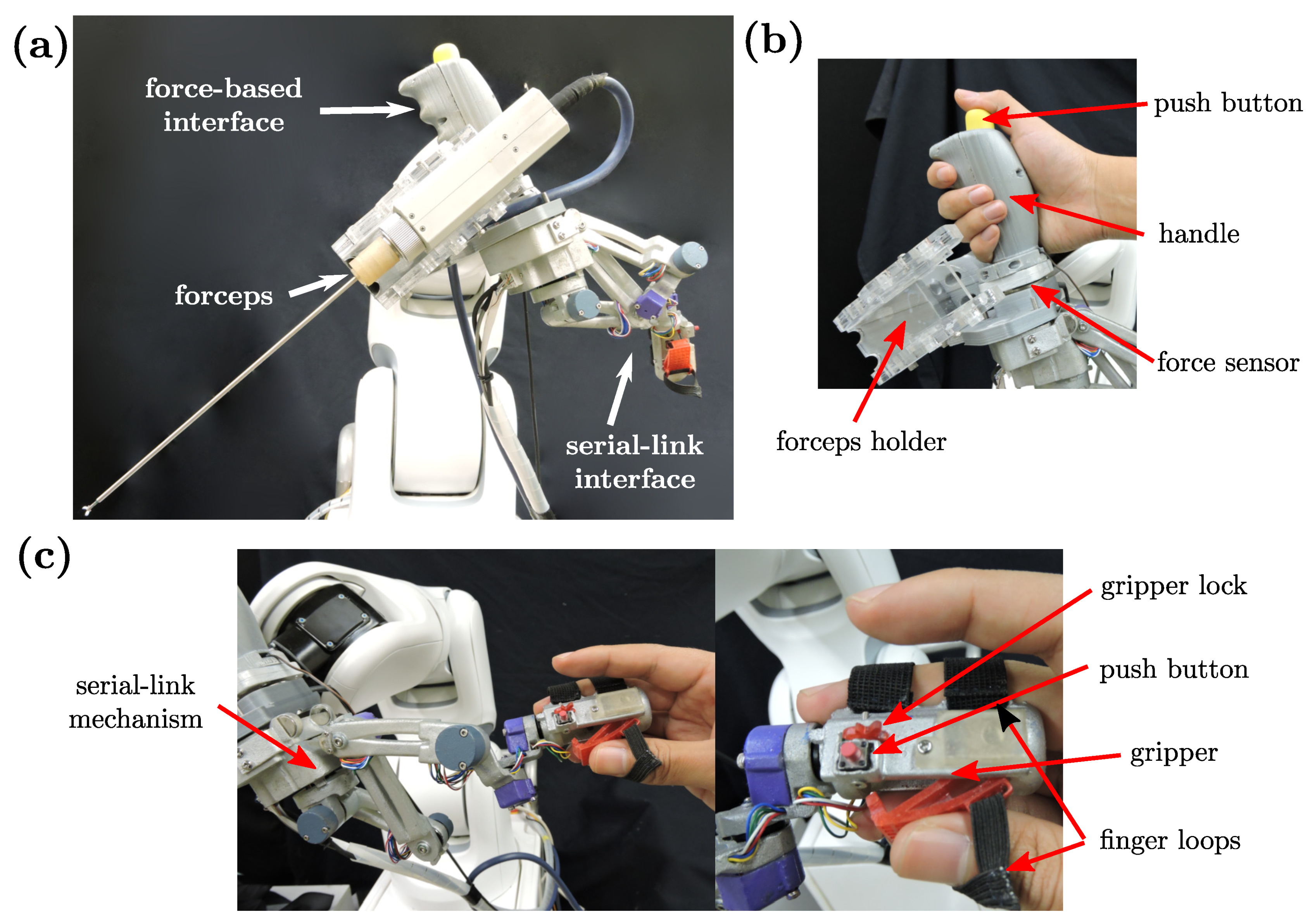
2.4. Cooperative Human-Robot Interface

We identified the following four repetitive activities during a common endonasal surgical operation: (1) positioning, (2) insertion, (3) manipulation, and (4) extraction. The surgeon first positioned the tip of the surgical instrument close to the nostril orifice and inserted the surgical instrument through the nasal cavity constrained by the nostril. Subsequently, once the target was reached, the surgeon performed a manipulation task. Finally, the instrument was extracted to replace the tool or finish the surgical procedure. In robot-assisted surgery, each activity would require a different level of assistance. From this observation, we define the following requirements for our human-robot interface as:
  • Workspace constraints
  • Multiple levels of assistance
  • Intuitive and ergonomic operation
  • Safe and stable operation
In this paper, we propose a hybrid human-robot cooperative interface designed to satisfy all these requirements. The proposed cooperative system was composed of a force based interface and a remote-controlled serial-link interface attached in a single device to control the position and the orientation of the articulated forceps. Different levels of assistance were provided by a state machine implemented with five states S n ( n { 1 , . . . , 5 } ) depending on the current surgical task, as shown in Figure 4, where S 1 is positioning, S 2 is insertion, S 3 is manipulation, S 4 is extraction, and S 5 is halt. First, the surgeon positioned the forceps from a neutral position to the nostril entrance ( S 1 ) using the force based interface. Then, a virtual remote-center-of-motion (VRCM) was set at this location, which constrained the motion of the forceps during the subsequent insertion sequence ( S 2 ). Once having reached the target zone, in the manipulation phase, the serial-link interface was used to control the articulated forceps tip motion and the robotic arm pose, simultaneously preserving the VRCM constraints ( S 3 ). Finally, the forceps were extracted again using the force based interface ( S 4 ). Once outside the nose, the VRCM was deactivated, and the robot could be freely positioned to a neutral position by the force based interface. As described above, the use of the interface was switched according to the state, where the force based interface was used during S 1 (positioning), S 2 (insertion), and S 4 (extraction) and the remote-controlled interface was used during S 3 (manipulation).

Mechanical Interface Design

The proposed interface (see Figure 5a–c) was equipped with an ergonomic vertical handle attached to a 6 axis force/torque sensor (Mini40, ATI Industrial Automation, North Carolina, USA) and a serial-link mechanism placed below. This interface also included a forceps slot for quick instrument exchange. In the force based control, the force exerted over the handle was used to operate the robot arm. The serial-link mechanism was composed of seven revolute joints and a gripper with finger loops for the middle finger and thumb, as well as a push-button in the handle. This serial-link interface provided a 6-DOF range of motion, allowing an additional redundant DOF to increase mobility and facilitate decoupling between the articulated interface motion and the robotic arm motion, i.e., the robot arm velocity B p ˙ A did not produce a change in the position of the interface’s gripper B p ˙ H = 0 . This could be achieved by compensating the robot arm motion with an internal motion of the interface joints. The gripper controlled the open/close motion of the forceps tip, and the push-button near the gripper activated the resting mode that kept the position of the robot fixed, e.g., while the surgeon was at rest or manipulating additional instruments. Each joint of the serial-link mechanism had a rotary position sensor (SV01, Murata) to measure the angle of the joint. The detailed kinematic structure with the D-H parameters is depicted in Figure 6.
To provide a comfortable position of the surgeon’s hands, the neutral position of the forceps tip was mapped with a 45 offset with respect to the wrist axis, as depicted in Figure 7a. The workspace of the serial-link mechanism is shown in Figure 7b.

2.5. Robot Motion Control

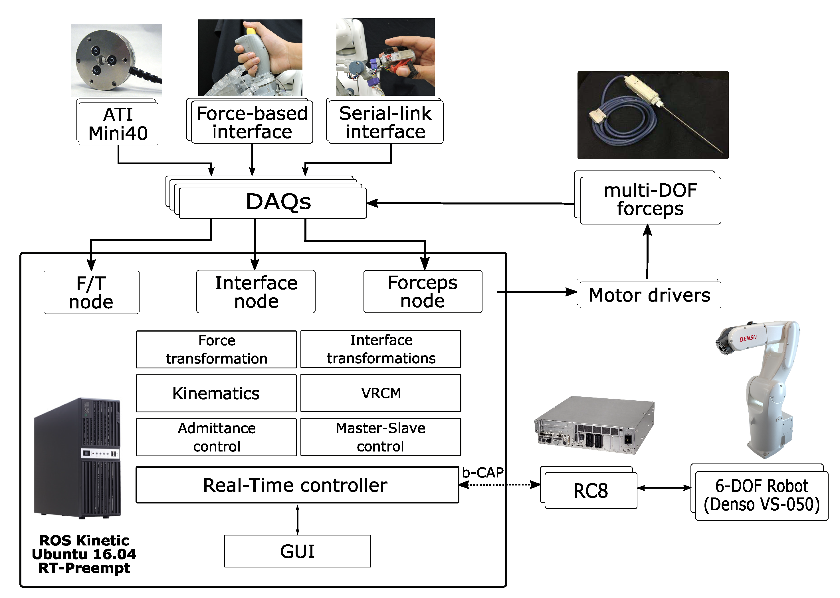
2.5.1. Software Architecture

The developed system architecture is depicted in Figure 8. In the proposed robotic surgical system, the control scheme consisted of two levels: one was a low-level joint motion controller, and the other was a high-level robot controller. At the low level, an industrial robot controller (RC8, DENSO Corporation, Aichi, Japan) controlled the manipulator joint positions, monitored arm singularities, and limited the joint velocities and workspace for safety motion. Motor drivers (ESCON, Maxon Motor, Sachseln, Switzerland) in the forceps controller box controlled the multi-DOF forceps joint positions. The high-level controller provided the target robot pose based on the input from the interface devices. The proposed control system was implemented on a 2.4 GHz Core i7 CONTEC computer running Linux (Ubuntu 16.04, Canonical) with real-time patches (RT-PREEMPT) and the Robot Operating System (ROS) framework on top of it. For the communication between the high-level controller and the robot manipulator, the b-CAP protocol was implemented with the C++ libraries provided by the robot manufacturer. The interface devices were connected to 16 bit data acquisition (DAQ) systems (PCI-1227U-AE, Advantech, USA), and the forceps low-level controller was connected to analog input/output boards (PCI-1216U-AE, Advantech, USA) and four axis encoder boards (PCI-1284-AE, Advantech, USA). The control loop ran at a rate of 500 Hz in synchronous mode with the RC8. In each cycle, the current robot pose was updated, and then, the target robot pose was computed and sent to the RC8 and the forceps controller box. In order to provide a modular and scalable architecture, communication with the interface devices was implemented as ROS nodes in the middleware level. In addition, virtual constraints (virtual RCM and workspace virtual walls) were implemented to enhance the operational safety by preventing damage to the surrounding tissues when accessing areas with high risks.

2.5.2. Positioning

To accomplish proper positioning of the articulated forceps before insertion, the robot followed the operator’s desired motion through forces/torques exerted over the commanding handle attached to the robot. An admittance control scheme was used to enable compliant motion of the manipulator [28]. The implemented admittance controller measured the externally applied forces/torques via the 6-DOF F/T sensor and generated the target velocity from the following admittance model bounded within the saturation limits:
F h = M v V ˙ e e + D v V e e
where F h 6 is the external force/torque command, V e e 6 and V ˙ e e 6 are the desired EE velocity and acceleration, respectively, and M v and D v 6 × 6 are constant positive definite diagonal matrices that represent the desired virtual mass and damping, respectively. The velocity and force vectors consisted of linear and angular components, respectively, as:
V e e = p ˙ e e ω e e , and F h = f h τ h .
The desired pose of the robot was then obtained by integrating the forceps tip target velocity. Figure 9 depicts a block diagram of the proposed 6-DOF cooperative force controller based on admittance control. Given the force/torque command applied by the surgeon f h and τ h , the discretized desired velocity of the forceps tip (EE) is obtained as follows:
B V e e [ k ] = M v B V e e [ k 1 ] + Δ T B F h [ k ] M v + Δ T D v
where k is a discrete time step and Δ T is the control period. We can then obtain the translational motion of the forceps tip as:
B p e e [ k ] = B p e e [ k 1 ] + Δ T B p ˙ e e [ k ] .
For the rotational motion, we used the relationship between the time derivative of the rotation matrix R and the angular velocity ω ,
R ˙ e e = S ( ω e e ) R e e
where S ( ω e e ) 3 × 3 is the angular velocity tensor (skew-symmetric matrix). The desired orientation of the EE can be computed by integrating (5) as:
B R e e [ k ] = B R e e [ k 1 ] e S ( Δ T ω e e [ k ] ) .
By using the Rodrigues rotation formula, we obtain:
B R e e [ k ] = B R e e [ k 1 ] ( I + sin σ S ^ + ( 1 cos σ ) S ^ 2 )
where S ^ is the normalized skew-matrix and σ is the magnitude of the rotation vector θ = Δ T ω e e :
σ = Δ T ω e e , and S ^ = S ( Δ T ω e e ) σ .
Note that we ensured the orthogonality of the resulting rotation matrix with QR decomposition using Householder reflections.

2.5.3. Insertion And Extraction

During the insertion and extraction of the robotic forceps, the same admittance controller presented in Section 2.5.2 was used, but with two additional features to ensure the safe and stable motion of the forceps inside the patient’s nasal cavity: variable admittance parameters and a virtual remote-center-of-motion (VRCM).

Variable Admittance Parameters

During the forceps insertion and extraction, a human-arm like motion was desired to provide intuitiveness and safe control of the forceps motion. Thus, a rapid movement was commonly performed close to the nostril area, whilst an accurate and slow positioning was preferred when reaching the target inside the sella region. In the admittance model, high precision and smooth motion could be achieved with high damping parameters, but large forces and time were needed. Low damping, on the other hand, required small forces and a short time, but the motion was less accurate. To this end, we implemented a variable admittance model, where the damping parameters in (1) were modified online in proportion to the distance between the forceps tip and the VRCM as:
D v = D v 0 + α p e e p v r c m
with
α = α d if ( V R C M p e e ) V R C M u x > 0 0 otherwise
where D v 0 is a constant initial damping matrix, α d is a positive constant, and V R C M u x is the unit vector along the forceps shaft.

Virtual Remote-Center-of-Motion

To prevent damage to the surrounding tissues and enhance operation safety, we introduced a VRCM at specific transition and task states, which was automatically activated at the transition ( T 1 ) phase and enabled during the insertion ( S 2 ), manipulation ( S 3 ), and extraction ( S 4 ) states. When the positioning ( S 1 ) state ended, the forceps tip was at the entrance of the nostril, and this position was recorded and the VRCM position fixed around this point. To constrain the movement of the forceps through the VRCM, we used a hard virtual fixture [29]. The force command F h was decomposed into the parallel ( F h ) and orthogonal ( F h ) components to the forceps shaft axis ( E E u x = V R C M u x ) as:
B F h = B F h || + B F h
where:
B F h = B F h ( B R V R C M V R C M u x ) .
We could now constrain the forceps motion with the of use a force/torque command ( B F d ) defined by:
B F d = f d τ d = B f h B τ h B τ h .
The parallel force component B f h and the orthogonal torque component B τ h = B τ h B τ h were selected to generate a translational velocity command along the direction of V R C M u x and to remove rotational motions around the same axis V R C M u x . As a result, the forceps motion was constrained within 3-DOF, only allowed to generate inclinations pivoted over the VRCM and translations along the shaft axis.

2.5.4. Manipulation

In the manipulation state, it was assumed that the forceps tip was situated in the target area. The multi-DOF forceps and the robot arm motion were controlled simultaneously by the 7-DOF serial-link interface. To match the workspace, the reference frame of the interface B p h r e f = B R I I p h r e f + B p r r e f and the target position B p t were registered during the transition T 3 by pressing the push button located at the top of the interface gripper and using the EE position as a reference B p g = B p e e .
Figure 10 depicts the block diagram of the master-slave controller achieving simultaneous control of the robot arm and the forceps tip by the serial-link interface for the manipulation state. The surgeon’s hand pose B X h = { B p h , B R h } was obtained from the interface, and the robot kinematics was computed at each control cycle. The master-slave controller scaled the surgeon’s hand displacement Δ X h by a factor of K s and generated the desired displacement of the forceps tip pose Δ X e e with respect to the target reference. We then obtained the desired EE pose, described as:
B p e e = B p g + K s [ B R I ( I p h I p h r e f ) + ( B p r B p r r e f ) ]
B R e e = B R I ( I R h I R h r e f ) B R I B R g .
To ensure the safety of the robot motion, two active constraints were implemented: workspace boundaries (virtual walls) and a VRCM.

Workspace Virtual Walls

With the workspace virtual walls, the forceps tip workspace was constrained within a cuboid with dimensions 40 × 25 × 40 mm, as shown in Figure 11a. Compared to other common workspace constraints (e.g., sphere or prism), a cuboid was simple to implement for faster computation and could provide a wider workspace for a knot tying task, in which the thread must be tightened by pulling the end of the suture using the forceps. The desired position of the forceps tip in the target frame G p e e = G R B B p e e + G p b was projected inside the cuboid as:
G p e e i i { x , y , z } = i m i n G p i i m i n i m a x G p i i m a x G p e e i otherwise
where i m i n and i m a x are the workspace predefined minimum and maximum limits, respectively. We then applied the inverse operation B p e e = G R B ( G p e e G p b ) to obtain again the desired forceps tip position in the base frame.

Virtual Remote Center of Motion (VRCM)

Once the desired pose of the forceps tip X e e was obtained, it was then split into a desired position command p e e d and an orientation command R e e d for a two level controller, giving priority to preserve the VRCM constraint defined in Section 2.5.3. We followed a simultaneous rotation-translation sequence [30] to reach the desired EE position p e e , as shown in Figure 11b.
First, we computed the unit vectors V R C M u g = V R C M p g V R C M p g , V R C M u e e d = V R C M p e e d V R C M p e e d from the target position and desired EE position, respectively. Next, the rotation operation to obtain V R C M u e e d from V R C M u g was represented as an angle-axis operation composed of an axis of rotation v and the angle of rotation θ , defined as:
V R C M v = V R C M u g × V R C M u e e d , and θ = arccos ( ( V R C M u g ) V R C M u e e d ) .
The same rotation was applied over the target frame to obtain the partial forceps tip orientation B R ^ e e :
B R ^ e e = B R ( v , θ ) B R e e .
To reach the desired orientation command B R e e , the additional DOF from the active forces were used. The complementary orientation is obtained as:
B R f o r c e p s = B R e e ( B R ^ e e ) ( r o l l d , y a w d , p i t c h d ) .
From the rotation matrix, a Euler angle representation ( r o l l d , y a w d , p i t c h d ) was generated for the multi-DOF forceps within the joints’ range of motion and projected onto the available DOF of the forceps (2-DOF: roll and grasp, 4-DOF: roll, yaw, pitch, and grasping).
The implementation of the VRCM was experimentally verified by a tracing task in which the forceps tip followed a trajectory defined by a circumference with a diameter of 2 cm. A magnetic motion capture (Aurora, Northern Digital Inc., Ontario, Canada) was used to track the position of a magnetic sensor placed over the forceps shaft where the VRCM was defined. We measured the RMS error between the position of the sensor and the VRCM, and we obtained a maximum RMS error of 1.59 mm and a median of 0.35 mm.

Online Trajectory Generation

The robot arm desired pose B X a = { B p a , B R a } is computed by frame transformations as:
B p a = B p e e B R A A p e e
and:
B R a = B R e e B R E E .
A smooth Cartesian EE trajectory was generated online by using the Reflexxes Type II Motion Library [31]. This online trajectory generator (OLT) provides commands for low-level motion control in real-time with position and velocity constraints. The TRAC-IK library [32] was used to enforce minimal configuration change combining two inverse kinematics approaches, pseudo-inverse Jacobian (22) and SQP-SS (23), which can be computed within the control loop of 500 Hz as:
q [ k ] = q [ k 1 ] + J p e r r
arg min q R 6 p e r r p e r r s . t . q b i , i = 1 , . . . , 6
where q represents the joint position, p e r r the Cartesian error vector, and b i the joint limits. For the transition to a halt state ( S 5 ), we used the current robot pose and null velocity as a target for the OLT. When the velocity reached zero, the halt state was enabled. For transitions between other states, the OLT ensured smooth transition with continuous position and velocity.

3. Experiments And Discussion

To evaluate the performance of our proposed scheme, we designed four testing experiments oriented toward testing the reachability, manipulability, and dexterity during common surgical tasks. We compared it with the use of conventional forceps used in endoscopic endonasal surgery. The following four tasks were performed by the participants using both the conventional surgical instruments and the proposed cooperative interface: (1) a reachability task to test the ability of the robot to reach anatomic areas of interest in endonasal surgery such as pituitary tumors in the sellar area, (2) a pick-and-place task to determine if the users can manipulate objects and translate them dexterously in a constrained environment, (3) a block-in-the-hole task to add the need of orientation adjustments in object manipulation, and (4) a needle stitching task to evaluate the performance in a common surgical task in endonasal surgery. All subjects gave their informed consent for inclusion before they participated in the study. The study was approved by the Ethical Research Committee of Nagoya University.

3.1. Experiment 1: Reachability

The aim of this experiment was to determine if potential users could operate the robotic system to position and insert an articulated forceps satisfactorily within the anatomical constraints of the nasal cavity to reach an area of interest. The experimental setup is presented in Figure 12a. We used a human head phantom (M01-SET-TSPS-E1, SurgTrainer Ltd., Ibaraki, Japan), prepared by a surgeon to expose the sphenoid sinus, and the area of interest was a pituitary adenoma model represented with a green mark (see Figure 12b). The head phantom was rigidly attached to a support and slightly tilted to resemble a normal clinical setup. A rigid endoscope ( 30 , 2.7 mm diameter) was used for visualization inside the head phantom and targeting the area of interest. The participants were asked to introduce a surgical tool from the left nostril and reach the area of interest with the use of conventional surgical instruments and with the proposed robotic system. A magnetic motion capture system (Aurora, Northern Digital Inc., Ontario, Canada) was utilized to measure the motions of the surgical instruments for both the manual and robot task operation. Five subjects between the ages of 20 and 35 participated in this experiment. We defined the optimal trajectory as the line connecting the center of the nostril and the center of the target pituitary region. The root mean squared error (RMSE) of the distance between trajectory performed and its projection over the optimal trajectory unit vector u o p t = x t a r g e t x n o s t r i l x t a r g e t x n o s t r i l was used as metric to evaluate the system performance as:
R M S E = i = 1 n s a m p l e s ( x ( x u o p t ) u o p t ) 2 n s a m p l e s .
A representative trajectory is shown in Figure 12c. The RMSE is shown in Figure 13a. The trajectory obtained with manual operation showed frequent direction changes and oscillations because of hand tremor. With the use of the proposed robotic system, the trajectory became smoother, and the deviation error was reduced by 30%. The time to complete the task is shown in Figure 13b. Although a velocity limitation of 10 mm/s was imposed on the robot, the completion time showed a 20% reduction with the proposed system compared with a manual insertion. The virtual remote-center-of-motion constrained the forceps motion to avoid collision with the surrounded tissue, and the variable damping in the force control provided stable and smooth motion control while approaching the target.

3.2. Experiment 2: Pick-and-Place and Experiment 3: Block-in-Hole

In the pick-and-place task, the forceps were employed to grasp four silicon tubes (inside diameter: 3 mm, outside diameter: 5 mm, length: 8 mm) and place them on numbered pegs (see Figure 14b). The testbed was placed 100 mm away from the nostril. Right and left hands were alternated for each silicon tube. The task was repeated three times for each hand with both the conventional instruments and the proposed cooperative user interface. The block-in-hole task was similar to the pick-and-place task with an additional need for orientation adjustments while positioning the blocks. The forceps were employed to grasp three blocks (two 5 mm edge cube and one 4 mm edge tetrahedron) and place them on the corresponding hole located under the initial hole, with a similar shape, but different orientation (see Figure 14c). The testbed was located 100 mm away from the nostril. Right and left hands were alternated for each block. The task was repeated three times for each participant with both the conventional instruments and the proposed cooperative user interface.
For the pick-and-place and block-in-hole tasks, a nose phantom was used (shown in Figure 14a). It comprised a 3D printed nose model and an acrylic platform for the testbeds. A magnetic motion capture system (Aurora, Northern Digital Inc., Ontario, Canada) was used to measure the motions of the surgical instrument for both the manual and robot task operation for evaluation purposes. For each trial, we considered the following aspects to evaluate the performance:
  • Task completion time (s): starting from the first contact with the tube/block until the release of the last tube/block.
  • Motion smoothness: we used the root mean squared jerk (RMSJ) [33] as a metric, defined by:
    R M S J = 1 t 1 t 0 t = t 0 t = t 1 x 2 d t .
Eight subjects between the ages of 20 and 35 who had no previous surgical training took part in these experiments. Before the experiments, each participant was instructed to practice for 5–10 min until they were familiarized with the operation. The results for the pick-and-place task are depicted in Figure 15.
The time to complete the pick-and-place task was approximately 66% longer with the use of our proposed system than the case of the manual operation of conventional forceps. This was expected due to the velocity limitation of 10 mm/s imposed on the forceps tip motion on the robot arm. Despite this, the root mean squared jerk, used as a metric of smoothness, showed approximately a 20% reduction of the variability and mean values when using our proposed system. A higher dexterity in the right hand compared with the left hand was observed as lower variability in the manual operation. In the case of the robotic system, both cases showed a similar variability, which indicated that similar levels of dexterity could be rapidly achieved for both hands. Furthermore, the combined box confidence interval did not show any overlap, which indicated that the robotic system provided a smoother motion compared with the use of conventional instruments.
The results for the block-in-hole are depicted in Figure 16. Similar to the pick-and-place task, the time to complete the block-in-hole task was approximately 66% longer with the use of our proposed system due to the velocity limitation. However, in this case, the root mean squared jerk showed more than a 40% reduction of the mean values when using our proposed system on both hands. The combined box confidence interval did not show any overlap, which indicated that the robotic system was able to provide a smoother motion compared with the use of conventional instruments when orientation adjustments and higher precision were required.

3.3. Experiment 4: Needle Stitching Task

The stitching task was intended to replicate a common task in endonasal surgery, where suturing of the dura matter is performed to prevent the leaking of cerebrospinal fluid. The experimental setup is shown Figure 14a with the testbed shown in Figure 14c. The same nose model of Experiment 2 and Experiment 3 was used for this task. A force sensor (Nano17, ATI Industrial Automation, North Carolina, USA) was placed behind the elastic tissue to register the force applied during the needle manipulation.
The task consisted of grasping a 6-0 surgical needle and puncturing an elastic tissue with a 6-0 surgical needle. The participants were asked to follow a five-step procedure: (1) remove the needle from its initial position, and insert it from a mark on the right tissue using the right forceps (R-Insertion); (2) extract the needle from under the tissue (R-Extraction); (3) hold the needle using the right forceps with a proper orientation (Regrasping); (4) insert the needle from under the left tissue (L-Insertion); (5) extract the needle using the left forceps (L-Extraction). A total of three series of the full task were requested of each participant. The needle was initially inserted in the tissue and had to be grasped with the right forceps for the insertion and the left forceps for the final extraction. Five subjects between the ages of 20 and 35 who had no previous surgical training participated in these experiments. Before the experiments, each participant was instructed about the procedure and practiced for up to 15 min until they were familiarized with the operation. We used both the 2-DOF forceps and the 4-DOF forceps for this experiment.
For each trial, we considered the following aspects to evaluate the task performance:
  • Task completion time (s): starting from removing the needle from its initial position until the complete needle extraction on the left side.
  • Interaction force (N): recorded with a force sensor placed behind the tissue.
The resulting task completion times are depicted in Figure 17. Using the proposed robotic system with the 2-DOF forceps exhibited a longer time, but with a shorter confidence interval for all the steps, except for the Regrasping step. Passing the needle with a proper orientation from one forceps to another required a precise control of the needle and was challenging to achieve without training. When using our proposed system, the time to perform this task was reduced by approximately 50%. With the robotic system and the 4-DOF forceps, the completion time was reduced for the R-Insertion and L-Insertion steps, and the Regrasping step was no longer needed because the R-Extraction could be performed easily with the right forceps thanks to the two additional DOF. For the R-Insertion and L-Extraction steps, the operation with both articulated forceps showed a higher completion time, which may be caused by the limitation in the grasping force of the articulated forceps used.
Figure 18 shows the force distribution resulting from the forceps interaction with the tissue during the needle insertion/extraction. The larger the number of bins close to 0 N, the less force applied to the tissue (less potential damage). The use of the robotic system (considering the use of both 2-DOF and 4-DOF forceps) reduced the range of applied force to almost half compared with the use of conventional forceps, from around [−0.4 N,0.4 N] to [−0.2 N, 0.2 N].
Finally, a complete stitching sequence achieved with the robotic system is shown in Figure 19.

4. Conclusions

In this paper, we proposed a cooperative human-robot interface for robot-assisted endoscopic endonasal surgery based on a hybrid concept of a force based and a serial-link interface to enhance intuitiveness and safety during highly dexterous anatomically constrained surgical tasks in EES. First, the surgical task was divided into stages, each of which was concerned with specific challenges and constraints. A force based interface was chosen for positioning, insertion, and extraction of the articulated forceps because of the simplicity and natural control arising from human-robot physical interaction. During the positioning stage, the robot worked in gravity compensation mode and followed the force applied by the surgeon over the interface. Then, the robot constrained the forceps motion along a virtual remote-center-of-motion fixed in the nostril during the insertion and extraction states. Once the tool was placed at the target workspace, we used a serial-link interface for precise control of the articulated forceps while keeping a virtual remote-center-of-motion at the nostril. Workspace constraints were implemented based on virtual fixtures to limit the tool workspace and ensure safe motion inside the patient. We defined the constraints from a phantom head to determine the sinus cavity and the dura workspace. We proposed a state based real-time controller that combined an admittance controller for positioning and insertion/extraction with a position tracker to control the forceps tip during the surgical task, ensuring smooth transition between these stages. Finally, we compared the performance of our proposed system with the use of conventional surgical instruments in common surgical tasks. A reachability experiment in a phantom head showed the capability of reaching the areas of interest such as the pituitary area in a smooth and precise way compared with the use of conventional instruments. Pick-and-place and block-in-hole experiments were performed to evaluate the manipulation of objects inside the nasal cavity under the anatomic constraints imposed by the nostril. The results showed a noticeable improvement in the motion smoothness. In addition, a needle stitching task was conducted to test the system in the highly dexterous surgical task. The robotic system showed a similar time for each phase, with a high reduction in the Regrasping phase, where passing the needle was challenging with the requirement of keeping a proper needle orientation. The same experiment showed a reduction in the force distribution applied over the tissue during the needle insertion/extraction. The results demonstrated that the proposed system could control and safely constrain the motion of bimanual robot arms with articulated multi-DOF forceps for endoscopic endonasal surgical tasks. Future work will focus on implementing optimization algorithms to generate a constrained trajectory that tracks the user interface motion during a complete multi-throw suturing sequence.

Author Contributions

Conceptualization, J.N. and Y.H.; methodology, J.C.; software, J.C.; experiments, J.C.; writing, original draft preparation, J.C.; writing, review and editing, J.N., T.A., and Y.H.; supervision, J.N., T.A., and Y.H.; project administration, Y.H.; funding acquisition, Y.H. All authors read and agreed to the published version of the manuscript.

Funding

This work was funded by the ImPACTProgram of the Council for Science, Technology and Innovation (Cabinet Office, Government of Japan).

Acknowledgments

We thank Murilo Marinho at the University of Tokyo for his assistance with the real-time control implementation and Tsuyoshi Ueyama at Denso Corporation for his help with the robot hardware setup.

Conflicts of Interest

The authors declare no conflict of interest.

References

  1. Cutler, A.R.; Barkhoudarian, G.; Griffiths, C.F.; Kelly, D.F. Transsphenoidal endoscopic skull base surgery: State of the art and future perspective. Innov. Neurosurg. 2013, 1, 15–35. [Google Scholar] [CrossRef]
  2. Kenan, K.; İhsan, A.; Dilek, O.; Burak, C.; Gurkan, K.; Savas, C. The learning curve in endoscopic pituitary surgery and our experience. Neurosurg. Rev. 2006, 29, 298–305. [Google Scholar] [CrossRef] [PubMed]
  3. Cimon, K.; Pautler, S. Robot-Assisted Surgery Compared with Open Surgery and Laparoscopic Surgery: Clinical Effectiveness and Economic Analyses. CADTH Technol. Rep. 2011. [Google Scholar] [PubMed]
  4. Schneider, J.S.; Burgner, J.; Webster, R.J.; Russell, P.T. Robotic surgery for the sinuses and skull base: What are the possibilities and what are the obstacles? Curr. Opin. Otolaryngol. Head Neck Surg. 2013, 21, 11–16. [Google Scholar] [CrossRef] [Green Version]
  5. Schleer, P.; Drobinsky, S.; de la Fuente, M.; Radermacher, K. Toward versatile cooperative surgical robotics: A review and future challenges. Int. J. Comput. Assist. Radiol. Surg. 2019, 14, 1673–1686. [Google Scholar] [CrossRef]
  6. Guthart, G.S.; Salisbury, J.K. The Intuitive telesurgery system: overview and application. In Proceedings of the 2000 IEEE International Conference on Robotics and Automation, San Francisco, CA, USA, 22–28 April 2000; pp. 618–621. [Google Scholar] [CrossRef]
  7. Massie, T.H.; Salisbury, J.K. The PHANTOM Haptic Interface: A Device for Probing Virtual Objects. In Proceedings of the ASME Winter Annual Meeting, Symposium on Haptic Interfaces for Virtual Environment and Teleoperator Systems, Chicago, IL, USA, November 1994; pp. 295–300. [Google Scholar]
  8. Tobergte, A.; Helmer, P.; Hagn, U.; Rouiller, P.; Thielmann, S.; Grange, S.; Albu-Schäffer, A.; Conti, F.; Hirzinger, G. The sigma.7 haptic interface for MiroSurge: A new bi-manual surgical console. In Proceedings of the 2011 IEEE/RSJ International Conference on Intelligent Robots and Systems, San Francisco, CA, USA, 25–30 September 2011; pp. 3023–3030. [Google Scholar] [CrossRef]
  9. Lee, J.Y.; O’Malley, B.W., Jr.; Newman, J.G.; Weinstein, G.S.; Lega, B.; Diaz, J.; Grady, M.S. Transoral robotic surgery of the skull base: A cadaver and feasibility study. ORL 2010, 72, 181–187. [Google Scholar] [CrossRef]
  10. Hanna, E.Y.; Holsinger, C.; DeMonte, F.; Kupferman, M. Robotic Endoscopic Surgery of the Skull Base. Arch. Otolaryngol. Neck Surg. 2007, 133, 1209. [Google Scholar] [CrossRef] [PubMed] [Green Version]
  11. Burgner, J.; Rucker, D.C.; Gilbert, H.B.; Swaney, P.J.; Russell, P.T.; Weaver, K.D.; Webster, R.J. A Telerobotic System for Transnasal Surgery. IEEE/ASME Trans. Mechatron. 2014, 19, 996–1006. [Google Scholar] [CrossRef] [Green Version]
  12. Piccigallo, M.; Focacci, F.; Tonet, O.; Megali, G.; Quaglia, C.; Dario, P. Hand-held robotic instrument for dextrous laparoscopic interventions. Int. J. Med Robot. Comput. Assist. Surg. 2008, 4, 331–338. [Google Scholar] [CrossRef]
  13. Zahraee, A.H.; Paik, J.K.; Szewczyk, J.; Morel, G. Toward the Development of a Hand-Held Surgical Robot for Laparoscopy. IEEE/ASME Trans. Mechatron. 2010, 15, 853–861. [Google Scholar] [CrossRef]
  14. MacLachlan, R.A.; Becker, B.C.; Tabarés, J.C.; Podnar, G.W.; Lobes, L.A., Jr.; Riviere, C.N. Micron: An Actively Stabilized Handheld Tool for Microsurgery. IEEE Trans. Robot. 2012, 28, 195–212. [Google Scholar] [CrossRef] [PubMed]
  15. Song, C.; Park, D.Y.; Gehlbach, P.L.; Park, S.J.; Kang, J.U. Fiber-optic OCT sensor guided “SMART” micro-forceps for microsurgery. Biomed. Opt. Express 2013, 4, 1045. [Google Scholar] [CrossRef] [PubMed] [Green Version]
  16. Payne, C.J.; Yang, G.Z. Hand-Held Medical Robots. Ann. Biomed. Eng. 2014, 42, 1594–1605. [Google Scholar] [CrossRef] [PubMed]
  17. Jakopec, M.; Baena, F.y.; Harris, S.J.; Gomes, P.; Cobb, J.; Davies, B.L. The Hands-on Orthopaedic Robot “Acrobot”: Early Clinical Trials of Total Knee Replacement Surgery. IEEE Trans. Robot. Autom. 2003, 19, 902–911. [Google Scholar] [CrossRef]
  18. Hagag, B.; Abovitz, R.; Kang, H.; Schmitz, B.; Conditt, M. RIO: Robotic-Arm Interactive Orthopedic System MAKOplasty: User Interactive Haptic Orthopedic Robotics. In Surgical Robotics; Springer: Boston, MA, USA, 2010; pp. 219–246. [Google Scholar] [CrossRef]
  19. Taylor, R.; Jensen, P.; Whitcomb, L.; Barnes, A.; Kumar, R.; Stoianovici, D.; Gupta, P.; Wang, Z.; Dejuan, E.; Kavoussi, L. A Steady-Hand Robotic System for Microsurgical Augmentation. Int. J. Robot. Res. 1999, 18, 1201–1210. [Google Scholar] [CrossRef]
  20. Matinfar, M.; Baird, C.; Batouli, A.; Clatterbuck, R.; Kazanzides, P. Robot-assisted skull base surgery. In Proceedings of the 2007 IEEE/RSJ International Conference on Intelligent Robots and Systems, San Diego, CA, USA, 29 October–2 November 2007; pp. 865–870. [Google Scholar] [CrossRef]
  21. Xia, T.; Baird, C.; Jallo, G.; Hayes, K.; Nakajima, N.; Hata, N.; Kazanzides, P. An integrated system for planning, navigation and robotic assistance for skull base surgery. Int. J. Med. Robot. Comput. Assist. Surg. 2008, 4, 321–330. [Google Scholar] [CrossRef] [Green Version]
  22. He, Y.; Hu, Y.; Zhang, P.; Zhao, B.; Qi, X.; Zhang, J. Human-Robot Cooperative Control Based on Virtual Fixture in Robot-Assisted Endoscopic Sinus Surgery. Appl. Sci. 2019, 9, 1659. [Google Scholar] [CrossRef] [Green Version]
  23. García, Á.M.; Rivas, I.; Turiel, J.P.; Muñoz, V.; Marinero, J.C.F.; de la Fuente, E.; Sabater, J.M. Integration of a Surgical Robotic Co-worker in an Endoscopic Neurosurgical Assistance Platform. In Robot 2019: Fourth Iberian Robotics Conference; Springer: Cham, Switzerland, 2020; pp. 453–464. [Google Scholar] [CrossRef]
  24. Travaglini, T.A.; Swaney, P.J.; Weaver, K.D.; Webster, R.J., III. Initial Experiments with the Leap Motion as a User Interface in Robotic Endonasal Surgery. In Robotics and Mechatronics. Mechanisms and Machine Science; Springer: Cham, Switzerland, 2016; Volume 37, pp. 171–179. [Google Scholar] [CrossRef] [Green Version]
  25. Nathan, C.A.; Chakradeo, V.; Malhotra, K.; D’Agostino, H.; Patwardhan, R. The Voice-Controlled Robotic Assist Scope Holder AESOP for the Endoscopic Approach to the Sella. Skull Base 2006, 16, 123–131. [Google Scholar] [CrossRef] [Green Version]
  26. Marinho, M.M.; Nakazawa, A.; Nakanishi, J.; Ueyama, T.; Hasegawa, Y.; Arata, J.; Mitsuishi, M.; Harada, K. Conceptual design of a versatile robot for minimally invasive transnasal microsurgery. In Proceedings of the 2016 International Symposium on Micro-NanoMechatronics and Human Science, Nagoya, Japan, 28–30 November 2016; pp. 65–66. [Google Scholar] [CrossRef]
  27. Arata, J.; Fujisawa, Y.; Nakadate, R.; Kiguchi, K.; Harada, K.; Mitsuishi, M.; Hashizume, M. Compliant four degree-of-freedom manipulator with locally deformable elastic elements for minimally invasive surgery. In Proceedings of the 2019 IEEE International Conference on Robotics and Automation, Montreal, QC, Canada, 20–24 May 2019; pp. 2663–2669. [Google Scholar] [CrossRef]
  28. Keemink, A.Q.; van der Kooij, H.; Stienen, A.H. Admittance control for physical human–robot interaction. Int. J. Robot. Res. 2018, 37, 1421–1444. [Google Scholar] [CrossRef] [Green Version]
  29. Bettini, A.; Marayong, P.; Lang, S.; Okamura, A.M.; Hager, G.D. Vision-Assisted Control for Manipulation Using Virtual Fixtures. IEEE Trans. Robot. 2004, 20, 953–966. [Google Scholar] [CrossRef] [Green Version]
  30. Marinho, M.M.; Bernardes, M.C.; Bo, A.P.L. Using General-Purpose Serial-Link Manipulators for Laparoscopic Surgery with Moving Remote Center of Motion. J. Med. Robot. Res. 2016, 1, 1650007. [Google Scholar] [CrossRef]
  31. Kröger, T.; Wahl, F.M. Online Trajectory Generation: Basic Concepts for Instantaneous Reactions to Unforeseen Events. IEEE Trans. Robot. 2010, 26, 94–111. [Google Scholar] [CrossRef]
  32. Beeson, P.; Ames, B. TRAC-IK: An open-source library for improved solving of generic inverse kinematics. In Proceedings of the 2015 IEEE-RAS 15th International Conference on Humanoid Robots, Seoul, Korea, 3–5 November 2015; pp. 928–935. [Google Scholar] [CrossRef]
  33. Young, R.P.; Marteniuk, R.G. Acquisition of a multi-articular kicking task: Jerk analysis demonstrates movements do not become smoother with learning. Hum. Mov. Sci. 1997, 16, 677–701. [Google Scholar] [CrossRef]
Figure 1. (a) Endoscopic endonasal surgery. (b) Instrument trajectory channel and the sellar target representation. (c,d) Physical human nasal model for endonasal surgery training. (e) 3D model of a human nasal model.
Applsci 10 04809 g001
Figure 2. (a) The proposed robotic surgical system based on the SmartArm concept for endoscopic endonasal surgery (EES). (b) 4-DOF articulated forceps [27]. (c) 2-DOF articulated forceps.
Applsci 10 04809 g002
Figure 3. Definition of the coordinate frames on the proposed robotic surgical system.
Applsci 10 04809 g003
Figure 4. State machine for surgical task characterization. The states defined are S 1 : positioning, S 2 : insertion, S 3 : manipulation, S 4 : extracting, and S 5 : halt. Transition states are represented with arrows: T 1 and T 2 are activated by the handle push-button; T 3 is activated by the gripper push-button; and T 4 is automatically activated when the tool is outside of the nostril. The virtual remote-center-of-motion (VRCM) position is set at the beginning of T 1 .
Applsci 10 04809 g004
Figure 5. (a) The proposed robotic surgical system. (b) Handle attached to a force sensor for the force-controlled interface. (c) Serial-link mechanism for the remote-controlled interface.
Applsci 10 04809 g005
Figure 6. Kinematic structure of the serial-link mechanism.
Applsci 10 04809 g006
Figure 7. (a) The neutral posture of the surgeon’s hands having a 45 offset to provide comfortable operation. (b) Serial-link mechanism workspace.
Applsci 10 04809 g007
Figure 8. Software architecture of the proposed robotic surgical system.
Applsci 10 04809 g008
Figure 9. Block diagram of the force based cooperative control.
Applsci 10 04809 g009
Figure 10. Block diagram of the master-slave controller.
Applsci 10 04809 g010
Figure 11. Virtual constraints. (a) Workspace virtual walls specified by a cuboid. (b) VRCM constraint implemented as a simultaneous rotation and translation along the VRCM frame.
Applsci 10 04809 g011
Figure 12. (a) Reachability experiment setup. (b) Adenoma model in the pituitary region represented with a green mark in the human head phantom. (c) Forceps tip trajectory comparison between manual and robot operation.
Applsci 10 04809 g012
Figure 13. (a) Root mean squared error (RMSE) between the trajectory performed and the optimal trajectory. (b) Task completion time.
Applsci 10 04809 g013
Figure 14. (a) Experiment setup. (b) Pick-and-place testbed. (c) Block-in-hole testbed. (d) Stitching testbed.
Applsci 10 04809 g014
Figure 15. Experimental results of the pick-and-place task.
Applsci 10 04809 g015
Figure 16. Experimental results of the block-in-hole task.
Applsci 10 04809 g016
Figure 17. Completion time for needle stitching per phases with the use of (a) regular forceps, (b) the robot with 2-DOF forceps, and (c) the robot with 4-DOF forceps. Note that in the case of (c) the robot + 4 DOF, the Regrasping phase is not needed with the benefit of the dexterity of the articulated forces, reducing the task completion time significantly.
Applsci 10 04809 g017
Figure 18. Force distribution during the needle insertion/extraction.
Applsci 10 04809 g018
Figure 19. Needle stitching sequence.
Applsci 10 04809 g019

