Article

Development of Energy-Based Impact Formula-Part II: Scabbing Depth, Scabbing Limit, and Perforation Limit

1
Department of Architectural Engineering, Kyonggi University, Suwon 16227, Korea
2
Department of Architecture and Architectural Engineering, Seoul National University, Seoul 08826, Korea
*
Author to whom correspondence should be addressed.
Appl. Sci. 2020, 10(16), 5481; https://doi.org/10.3390/app10165481
Submission received: 21 June 2020 / Revised: 1 August 2020 / Accepted: 5 August 2020 / Published: 7 August 2020

Abstract

:
Numerous formulae are available for predicting the scabbing limit and perforation limit thicknesses subjected to impact loading, but no formula has yet been proposed for estimating the scabbing depth, which is the damaged depth at the rear face when the back of the concrete panel is peeled. In this paper, a new energy-based impact formula along with a theoretical background is proposed to estimate the scabbing depth, scabbing limit, and perforation limit. Based on the scabbing theory, energy–depth relation, and energy conservation law, the new formula is developed and verified with test results. Compared to other impact formulae, the proposed impact formula is found to be more effective.

1. Introduction

Concrete and steel materials are two of the most common construction materials [1,2,3,4]. Concrete or concrete–steel composite plate members are often exposed to high strain-rate loading, such as blasts and impacts [5], and there are impact formulae for estimating the local damage caused by high-velocity impact loading. These impact formulae are classified into penetration depth, scabbing limit, and perforation limit formulae, where the scabbing and perforation limits indicate the minimum thicknesses required to prevent scabbing and perforation, respectively [6,7,8]. Penetration depth, in particular, has been extensively studied, and over 27 formulae have been proposed, so far, for predicting local damage [9,10,11,12,13,14,15,16,17,18,19,20,21]. However, despite the importance of scabbing and perforation limit formulae in assessing secondary risk, they are fewer than the penetration depth formulae proposed so far. Secondary critical threats, such as chemical and biological weapons, conventional weapons, and soldiers, can enter concrete structures through perforated holes, even if a building does not collapse. When a spalling/scabbing failure occurs due to impact loadings, the fragments/debris can fly into people/things in concrete structures, resulting in secondary physical and personal damage. As the thickness of the concrete panels increases, the safety of the concrete structures against external threats is enhanced. However, the concrete thickness cannot be increased to an unlimited extent and increasing it can be very expensive. Therefore, the scabbing and perforation limits are as important as the penetration depth.
To estimate the damage level of the concrete member caused by impact loadings, various studies have been conducted. Most studies first focused on deriving the penetration depth using the force–penetration relation, and then derived the scabbing and perforation limit formulae from the regression analysis conducted using the relations between penetration depth and low boundary of scabbing and perforation [17]. In other words, there are hardly any scabbing and perforation limit formulae obtained using the theoretical background.
Hwang et al. [12] proposed energy-based penetration depth based on the theoretical background. Kim and Kang [22] defined the impact mechanism and energies involved and proposed the penetration depth formula using the energy conservation law. The impact mechanism involves seven types of energy: kinetic energy (KE), deformed energy of the projectile (EDP), elastically deformed energy of the concrete panel (EEP), overall deformed energy of the concrete panel (ESD), spalling-resistant energy (ESP), tunneling-resistant energy (ET), and scabbing-resistant energy (ESC). Of these, scabbing-resistant energy occurs in the case where the target concrete panel is insufficient to absorb the spalling-resistant energy and/or tunneling-resistant energy.
In this paper, the condition of scabbing failure, including perforation failure, is theoretically defined using the energy-depth relation and scabbing-resistant energy. Also, the scabbing depth, scabbing limit, and perforation limit formulae underpinned by a theoretical framework are proposed rather than that based on the experimental results. In particular, this study is important in that the scabbing depth formula is proposed, since there have been no prior existing formulae to estimate scabbing depth. The proposed impact formulae are then compared with the existing data.

2. Literature Review

Kim et al. [6] summarized the history and key points of impact formulae and described some representative scabbing and perforation limit formulae in detail. The Army Corps of Engineers (ACE) proposed an impact formula based on extensive impact tests [9], conducted using 37, 75, 76.2, and 155 mm steel cylindrical missiles. After obtaining additional experimental data for 0.5 caliber bullets, the scabbing and perforation limit thickness formulae were modified (Equations (4) and (5)). Additional tests were conducted with a panel thickness of 3–18 times the projectile diameter and a concrete strength of 10–50 MPa. The difference between Equations (2), (3) and Equations (4), (5) is within 10%. The data for larger missiles were analyzed using the original formula. Therefore, Equations (2) and (3) are more appropriate for designing the impact resistance of nuclear power plants [11].
x p e d p = 3.5 × 10 4 f c ( M p d p 3 ) d p 0.215 V i m p 1.5 + 0.5
h p f d p = 1.32 + 1.24 x p e d p   for   1.35 < x p e d p < 13.5   or   3 < h p f d p < 18
h s c d p = 2.12 + 1.36 x p e d p   for   0.65 < x p e d p 11.75   or   3 < h s c d p 18
h p f d p = 1.23 + 1.07 x p e d p   for   1.35 < x p e d p < 13.5   or   3 < h p f d p < 18
h s c d p = 2.28 + 1.13 ( x p e d p )   for   0.65 < x p e d p 11.75   or   3 < h s c d p 18
where xpe is the penetration depth (m); Mp is the mass of the projectile (kg); dp is the diameter of the projectile (m); Vimp is the impact velocity of the projectile (m/s); f’c is the compressive strength of concrete (Pa); hpf is the perforation limit thickness (m); and hsc is the scabbing limit thickness (m).
The National Defense Research Committee (NDRC) suggested impact formulae based on the results of the impact tests conducted by ACE and further experiments. The impact function (G-function), concrete penetrability factor (K), and nose shape factor (Np) were introduced, where Np had values of 0.72, 0.84, 1.0, and 1.14 for flat, hemispherical, blunt, and very sharp noses, respectively. The concrete penetrability factor was further studied in the 1960s by Kennedy, and the original NDRC formula was modified as shown in Equations (6) and (7). The scabbing and perforation limit formulae, which are related to penetration depth, were proposed as shown in Equations (8) to (11).
G = 3.8 × 10 5 N M p d p f c ( V i m p d p ) 1.8
G = ( x p e 2 d p ) 2   for   x p e d p 2   or   G = x p e d p 1   for   x p e d p > 2
h p f d p = 3.19 ( x p e d p ) 0.718 ( x p e d p ) 2   for   x d 1.35
h p f d p = 1.32 + 1.24 ( x p e d p )   for   1.35 < x p e d p < 13.5
h s c d p = 7.91 ( x p e d p ) 5.06 ( x p e d p ) 2   for   x p e d p 0.65
h s c d p = 2.12 + 1.36 ( x p e d p )   for   0.65 < x p e d p 11.75
where xpe is the penetration depth (m); Np is the nose shape factor (0.72, 0.84, 1.0 and 1.14 for flat, hemispherical, blunt and very sharp noses, respectively); Mp is the mass of the projectile (kg); dp is the diameter of the projectile (m); Vimp is the impact velocity of the projectile (m/s); hpf is the perforation limit thickness (m); hsc is the scabbing limit thickness (m); and f’c is the compressive strength of concrete (Pa).
After World War II, the safety of nuclear power plants became a major issue, and the impact resistance of concrete members was extensively studied. Hughes [17] proposed an impact formula with a dynamic increase factor (SHughes), considering the strain rate effect of concrete materials (Equations (12) to (19)). Hughes suggested that, unlike the other impact formulae, the tensile strength of concrete governs the impact mechanism, and developed a dimensionless impact factor considering this fact. The penetration depth formula was derived from the force-penetration depth model, and the perforation limit thickness and scabbing limit were derived from the upper bounds of the data.
S H u g h e s = 1 + 12.3 ln ( 1 + 0.03 I )
I = M p V i m p 2 f r d p 3
f r = 0.63 f c
x p e d p = 0.19 N p I S H u g h e s ;   I < 3500
h p f d p = 3.6 x p e d p   for   x p e d p < 3.5
h p f d p = 1.58 x p e d p + 1.4   for   x p e d p 3.5
h s c d p = 5.0 x p e d p   for   x p e d p < 3.5
h s c d p = 1.74 x p e d p + 2.3   for   x p e d p 3.5
where, xpe is the penetration depth (m); fr is the tensile strength of concrete (Pa); Mp is the mass of the projectile (kg); dp is the diameter of the projectile (m); Vimp is the impact velocity of the projectile (m/s); Np is the nose shape factor (1, 1.12, 1.26, and 1.39 for flat, blunt, spherical and very sharp noses, respectively); f’c is the compressive strength of the concrete (Pa); hsc is the scabbing limit thickness (m); and hpf is the perforation limit thickness (m).

3. Development of Scabbing Depth Formula

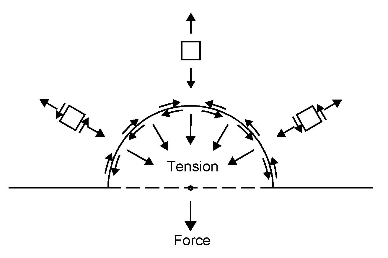
In Part I of Kim and Kang’s paper [22], the scabbing failure could occur in the case where the target concrete panel’s thickness was insufficient to absorb the impact energy (Figure 1). The impact force from the collided point at the front face was transmitted to the opposite face, and reflected and transferred to the tensile force, which could peel the concrete panel. Based on the scabbing failure mode and theoretical background studied by Park et al. [23], the stress flow is defined as shown in Figure 2. Similar to the slab punching failure studied by Choi et al. [24], the rear face failure is governed by the tension stress and shear stress. The dynamic shear stress (Equations (20)–(24)) capacity controlled by the dynamic tension was derived by Kim and Kang [22]. Herein, if there was no measured concrete tensile strength (ft,st), the fib Model Code 2010 [25] provided the equation for obtaining the tensile strength of concrete, based on compressive strength.
v n t , d y n ( z ) = 0.24 ( f t , d y n ) 2 + 0.25 f t , d y n f c , d y n
f c , d y n f c , s t = ( ε ˙ 30 × 10 6 ) 0.014   for   ε ˙ c 30   s 1
f c , d y n f c , s t = 0.012 ( ε ˙ 30 × 10 6 ) 1 / 3   for   ε ˙ c > 30   s 1
f t , d y n f t , s t = ( ε ˙ 1 × 10 6 ) 0.018   for   ε ˙ c t 10   s 1
f t , d y n f t , s t = 0.0062 ( ε ˙ 1 × 10 6 ) 1 / 3   for   ε ˙ c t > 10   s 1
where, vnt,dyn(z) is the dynamic shear stress capacity (MPa) controlled by the dynamic tension; f’c,dyn is the dynamic compress stress of concrete (MPa); ft,dyn is the dynamic tensile stress of concrete (MPa); f’c,st is the the compressive stress of concrete under the static loading (MPa); ft,st is the tensile stress of concrete under the static loading (MPa); and ε ˙ is the strain rate.
The steel fiber-reinforced concrete has higher tensile strength than normal concrete, and leads to reduced scabbing failure [6]. Therefore, the tensile strength resulting from steel fibers should be considered the predicted tensile strength depending on the length and diameter of the steel fiber, and the steel fiber volume fraction can be obtained from Equation (25) below, which was derived in the Part I paper (also available in the first author’s dissertation).
f t s , d y n = f t , d y n ( 1 + 2 3 l f d f V f )
where, fts,dyn is the dynamic tensile stress of steel fiber-reinforced concrete affected by strain rate, respectively; lf is the steel fiber length (mm); df is the steel fiber diameter (mm); and Vf is the steel fiber volume fraction (%).

3.1. Scabbing-Resistant Energy

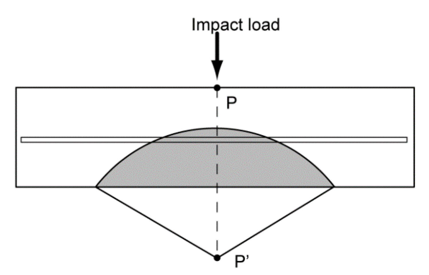
The scabbing theory was introduced to derive the scabbing-resistant energy. According to this theory [8,26], compressive stress is generated and radiated from the force induced at the impact point on the front face, P, in Figure 3, and is transferred to the rear face of the panel. The transferred stress is transformed into tensile stress, assuming that the tensile stress is generated and reflected at the free point (P′), as shown in Figure 3. If the tensile stress exceeds the properties of the concrete, scabbing occurs. The force (Fsc) acting between the scabbed concrete cone and the slab can be obtained similarly as spalling-resistant energy is obtained (Equation (26)). The scabbing-resistant energy should be considered for the tensile effect of the rebar, and can be obtained using the acting force and energy density (Equation (27)).
F s c = [ v n t , d y n π ( d p + x s c tan θ s c ) x s c cos θ s c + v n t , d y n π d p 2 4 ]
E s c = [ v n t , d y n π ( d p + x s c tan θ s ) x s c cos θ s + v n t , d y n π d p 2 4 ] α 2 V s c A s c
where, Fsc is the force upon between the scabbed concrete cone and the concrete panel (N); Esc is the scabbing-resistant energy (kN-m); vnt,dyn is the tensile strength of concrete controlled by the compression under the dynamic loading (MPa); dp is the sectional diameter of the projectile (mm); xsc is the scabbing depth (mm); θsc is the angle of the scabbed cone (degree); Volsc is the volume of the scabbed cone (mm3); and Asc is the base area of the scabbed cone (mm2).
Herein, how much energy reaches and is reflected from the rear face of a concrete panel is very important for predicting the scabbing phenomenon. To estimate the amount of reached or reflected energy, the stress-depth relation of contact theory is used. The stress distribution for the half-space along the z-axis is shown in Equation (28) [27].
σ z = P c t , max ( z c t 2 a c t 2 + 1 ) 1
where, σ z is the stress at zct point; Pct,max is the maximum force on contact point; zct is the distance from a contact point along z-direction; and act is the radius of the contact area.
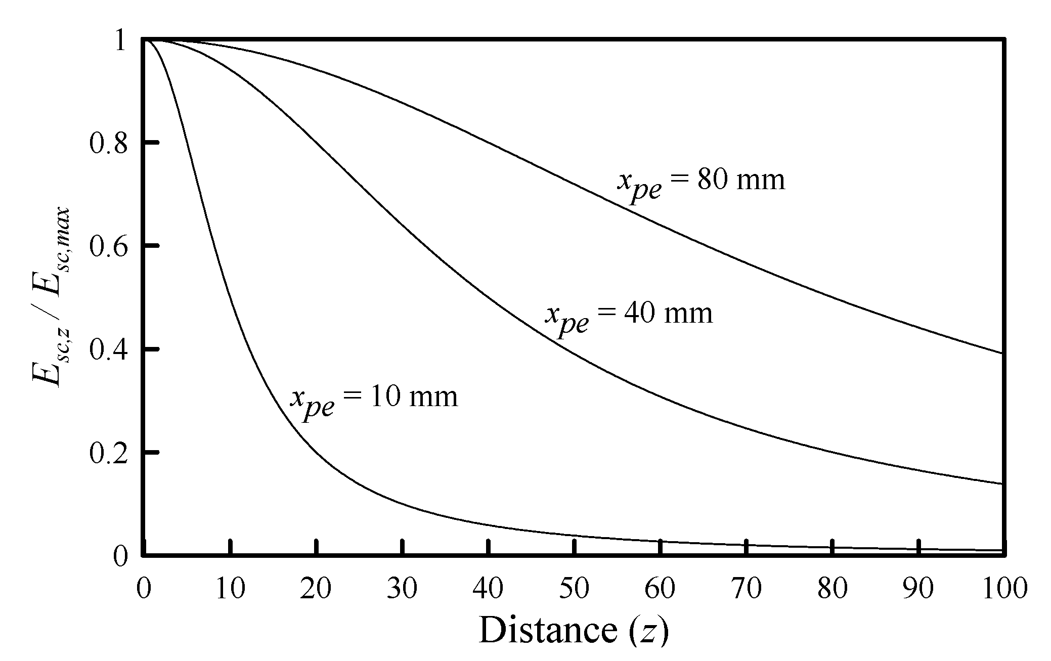
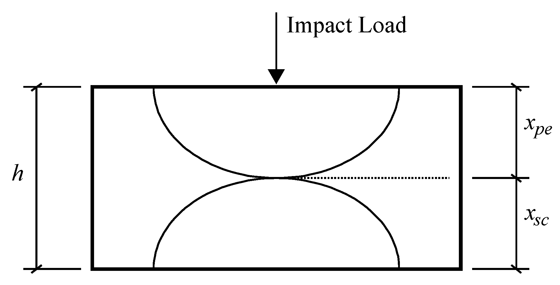
The load (Pct,max) in Equation (28) can be considered as an energy, which can be expressed as Equation (29). Here, act is assumed to be equal to the sectional radius of the projectile. If the penetration depth (xpe) is deeper than the sectional radius of the projectile, act can be considered as the penetration depth. However, if the penetration depth is less than the radius of the sectional radius of the projectile, the value of act should be changed. In Hertzian contact theory, act is the radius of the contact area, which is considered the penetration depth (xpe) in this paper. In other words, the spalled cone is assumed to be in contact with the unpenetrated slab at the penetration depth, as shown in Figure 4. In summary, act is the penetration depth if the penetration depth is greater than the projectile radius, and act is the projectile radius if the penetration depth is less than the projectile radius. The energy reflected from the rear face of the slab can be defined as Equation (30). As Ez is equal to Esc, Equations (27) and (30) become Equation (31). The relations between distance and Esc,z-to-Esc,max ratio according to various penetration depths are plotted in Figure 5.
E z = E max ( z c t 2 a c t 2 + 1 ) 1
E z = E max ( ( h x p e x t ) 2 ( x p e x t ) 2 + 1 ) 1 = E s c , max
E s c , z = E s c , max ( ( h x p e x t ) 2 ( x p e x t ) 2 + 1 ) 1 = [ v n t , d y n π ( d p + x s c tan θ s ) x s c cos θ s + v n t , d y n π d p 2 4 ] α 2 V o l s c A s c
where, Esc,z is the scabbing energy at zct point (N-mm); Esc,max is the maximum energy on contact point (N-mm); zct is the distance from a contact point along z-direction (mm); act is the radius of the contact area (mm); h is the thickness of reinforced concrete panel (mm); xpe is the penetration depth (mm); xt is the tunneling depth (mm); vnt,dyn is the shear stress controlled by tension under the dynamic loading (MPa); dp is the diameter of the projectile (mm); xsc is the scabbing depth (mm); As is the sectional area of reinforcing bar (mm); α2 is the projectile length factor; Volsc is the volume of scabbed cone (mm3); and Asc is the area of scabbed cone (mm).

3.2. Derivation of Scabbing Depth Formula

The scabbing depth (xsc) can be obtained using the scabbing-resistant energy (Equation (32)). When the scabbed cone shape is assumed to be hemispherical, Equation (32) is rearranged with respect to the scabbing depth, as shown in Equations (33) and (34).
E s c , z = E s c , max ( ( h x p e x t ) 2 ( x p e x t ) 2 + 1 ) 1 = [ v n t , d y n π ( d p + x s c tan θ s ) x s c cos θ s + v n t , d y n π d p 2 4 ] α 2 V o l s c A s c
x s c = E s c , z × 6 × α 2 8 × v n t , d y n × π 3
α 2 = ln ( 0.8 + l p d p )
where, Esc,z is the scabbing energy at zct point (N-mm); Esc,max is the maximum energy on contact point (N-mm); h is the thickness of reinforced concrete panel (mm); xpe is the penetration depth (mm); xt is the tunneling depth (mm); vnt,dyn is the shear stress controlled by tension under the dynamic loading (MPa); dp is the diameter of the projectile (mm); xsc is the scabbing depth (mm); As is the sectional area of reinforcing bar (mm); θsc is the angle of the scabbed cone (degree); Volsc is the volume of scabbed cone (mm3); Asc is the area of scabbed cone (mm); and α2 is the projectile length factor.

3.3. Derivation of Scabbing Limit Formula

The scabbing energy (Esc,z) converges to zero as the distance from the collision point becomes deeper (Figure 5); however, it does not reach zero. At this time, the partially reflected energy would offset EEP and ESD, because the overall deformed and elastic penetrated slab will return to normal. The remaining thickness (h–xpe–xt) for preventing the scabbing phenomenon can absorb the remaining energy, which is obtained by subtracting EEP and ESD from ESP, as shown in Equation (35). However, EEP and ESD cannot be calculated because the slab thickness is unknown. As the values of EEP and ESD are not large, they are neglected in Equation (36). As mentioned above, the equation converges but does not reach zero; thus, an appropriate lower limit value should be presented. Here, the lower limit assumes 5% of ESC. The 5% of the remaining energy is expected to be consumed by cracks in the rear face of a reinforced concrete panel. Therefore, the value of h in Equation (37) can be summarized in Equation (38), where h is equal to the scabbing limit thickness (hsc).
E S P E E P E S D = E S C , r e m a i n
E S P = E S C , r e m a i n
E s c ( ( h ( x p e + x t ) ) 2 ( x p e + x t ) 2 + 1 ) 1 = E s c , r e m a i n = 0.05 E S P
h = h s c = 5.36 ( x p e + x t )
where, ESP is the spalling resistant energy (N-mm); EEP is the elastic penetrated energy (N-mm); ESD is the overall deformed energy of panel (N-mm); ESC,remain is the remaininig energy (N-mm) to be absorbed in the panel; ESC is the scabbing resistant energy (N-mm); h is the thickness of the panel (mm); xpe is the penetration depth (mm); hsc is the scabbing limit thickness (mm); and xt is the tunneling depth (mm).

3.4. Derivation of Perforation Limit Formula

A perforation can occur when the sum of penetration depth (xpe), tunneling depth (xt), and scabbing depth (xsc) exceeds the panel thickness, as shown in Figure 6. Therefore, in this paper, the perforation limit thickness (hpf) can be obtained as the sum of xpe, xt, and xsc, as shown in Equation (39).
h p f = x p e + x t + x s c
where, hpf is the perforation limit thickness (mm); xpe is the penetration depth (mm); xt is the tunneling depth (mm); and xsc is the scabbing depth (mm).
Similar to the scabbing limit thickness, the perforation limit thickness can be used to calculate the thickness of the reinforced concrete panel to prevent the perforation. The elastic penetrated energy (EEP) and overall deformed energy (ESP), which can be obtained only by knowing the thickness of the reinforced concrete panel, should be neglected. When calculating the penetration, tunneling, and scabbing depths required in Equation (38), only the energy measured by not considering EEP and ESP should be used.

4. Verification of Energy-Based Impact Formula

4.1. Scabbing Depth Assessment

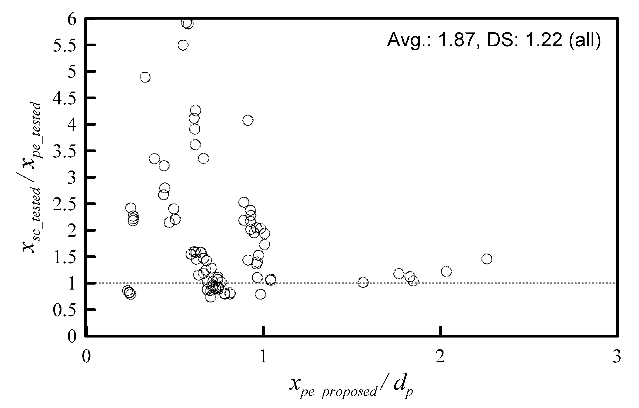
As mentioned in the Introduction, there is no formula that predicts the scabbing depth, which is a failure on the rear face of the concrete panel. In this section, the newly proposed scabbing depth formula is verified using the experimental results. However, there is little experimental data on scabbing depth, as the penetration depth and penetration were the main objectives in the previous impact studies. According to the experimental results obtained by Abdel-Kader [28] and Kim [29], 81 specimens were measured for scabbing depth, and the ratios of tested-to-predicted scabbing depth are shown in Figure 7.
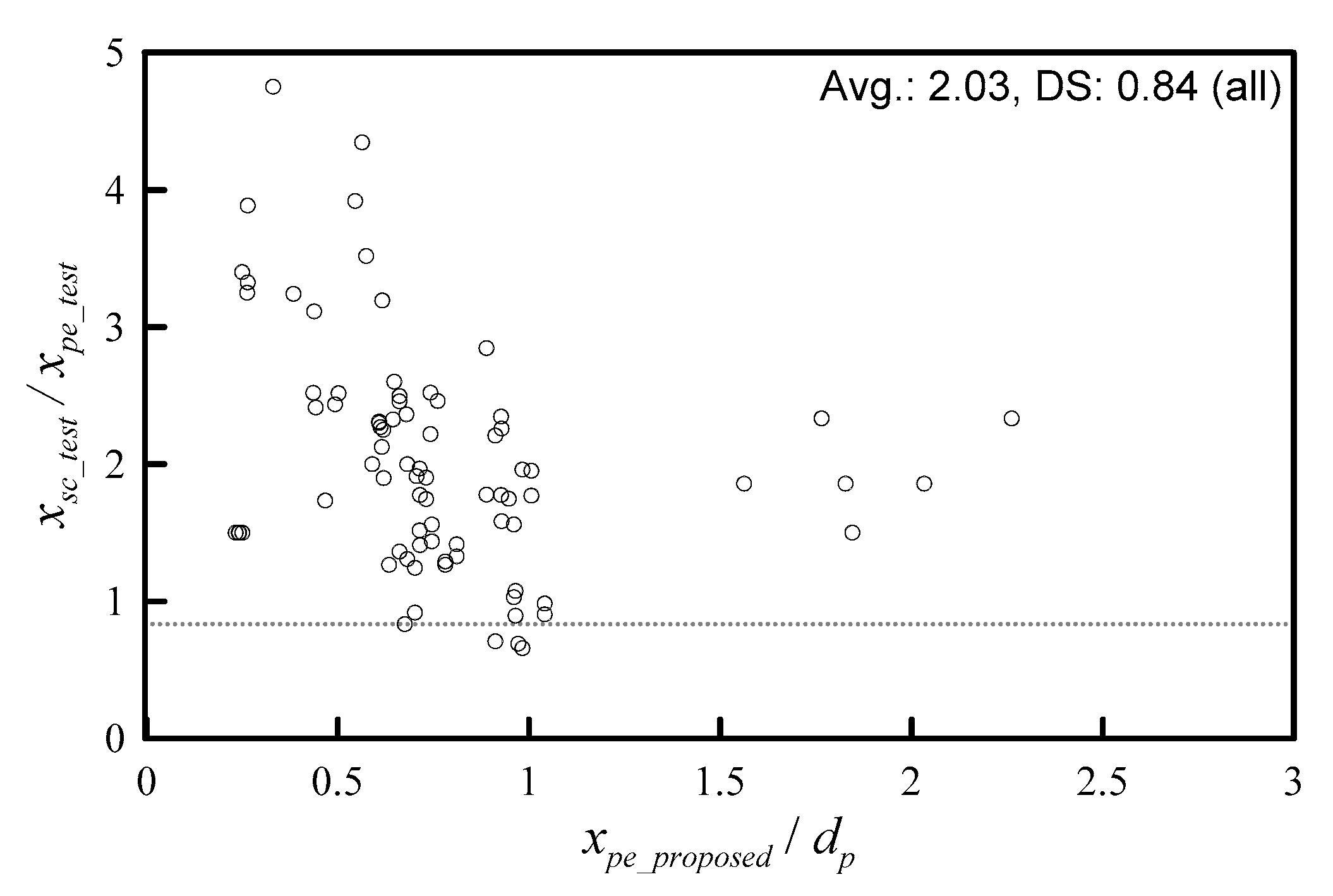
The minimum and maximum ratios of the tested-to-predicted scabbing depth were 0.74 and 5.92, respectively. Of the 81 specimens, 52 were predicted at a ratio of 2 or less, with an average of 1.16. On the other hand, 29 specimens were predicted with a ratio of 2 or more, with an average of 3.14 (Table 1). The accuracy was lower than that of the penetration depth prediction formula. Similar penetration depths were observed in the impact experiments conducted under similar conditions. However, the scabbing depths were not similar even under the same conditions. Figure 8 shows the tested scabbing depth-to-tested penetration depth ratios, most of which are scattered below 2.5. However, for some specimens, the ratios are observed to be above 3, with a maximum value of about 5. In other words, it is quite difficult to predict the scabbing depth. As the reflected energy may be amplified depending on the reflection angle and the properties of materials in the concrete matrix, it is not easy to predict the reflected energy accurately. Despite these difficulties, the scabbing depth prediction formula presented in this paper seems to be predicted quite well.

4.2. Scabbing Limit Assessment

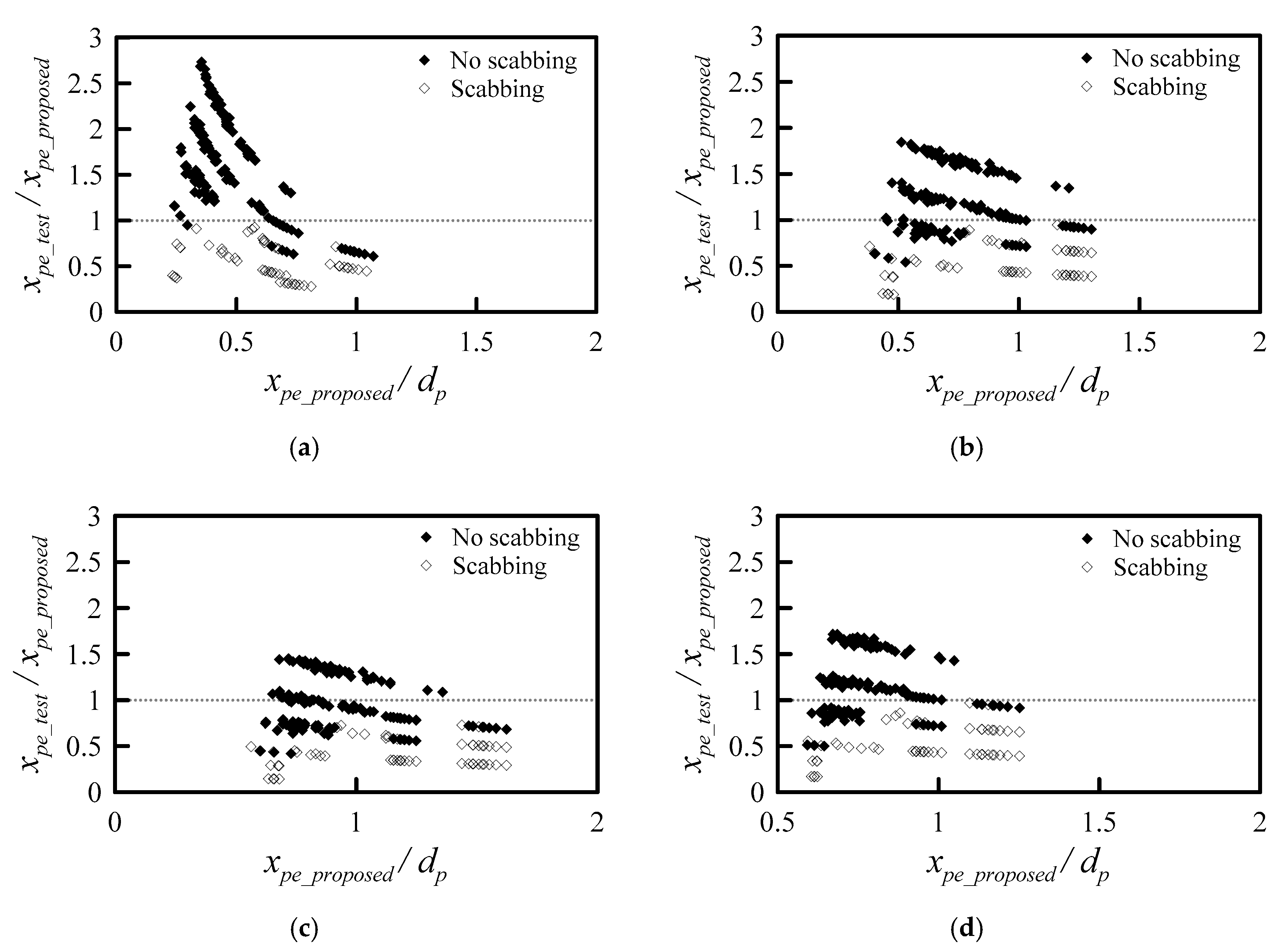
Based on the energy-depth relation, a new scabbing limit thickness formula is proposed and the thickness required to absorb 95% spalling and tunneling energy is suggested. Figure 9 shows the panel thickness (h) divided by the predicted scabbing limit thickness (hsc), based on the new proposed formula. The modified NDRC, Hughes, and UK Atomic Energy Authority (UKAEA) formulae predict the penetration depth well, as shown in the Paper I [22]. Only the experimental results obtained from the test program conducted by Kim [29] are used for the analysis of scabbing limit thickness, because all other experimental results in other studies presented unclear scabbing depth and failures.
As shown in Figure 9, the specimen with the scabbed failure is assumed to lie below 1 [30]. Table 2 shows the accuracy of the scabbing limit thickness formula. The four formulae predict that all specimens incur scabbing failure. However, each formula shows different prediction results, where the specimens should not scab on the rear face of the concrete panel. The proposed scabbing limit thickness formula is predicted such that 139 specimens do not incur scabbing failure. No scabbing failure is observed in 172 specimens, and the proposed formula is ~81% accurate. In addition, in 33 specimens, scabbing failure is predicted to occur but does not occur. The NDRC, Hughes, and ACE formulae are 66%, 43%, and 66% accurate, respectively. Therefore, our proposed scabbing limit thickness formula turns out to be the most accurate.

4.3. Perforation Limit Assessment

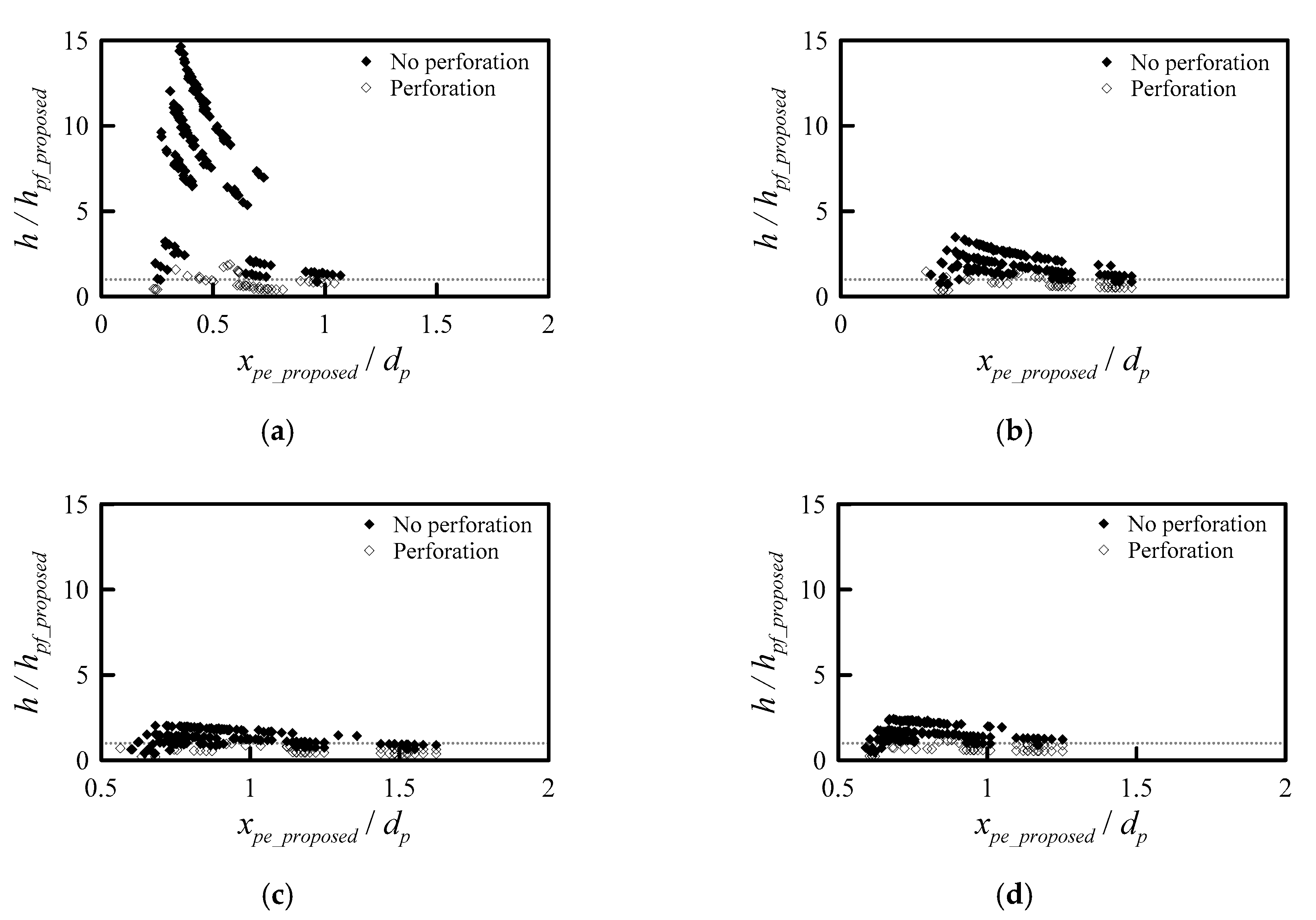
The perforation limit thickness formula is newly suggested as Equation (38), and is equal to the sum of penetration depth (xpe), tunneling depth (xt), and scabbing depth (xsc). To verify this formula, only the experimental results obtained by Kim [29] are likely used in the assessment of the scabbing limit formula. The modified NDRC, Hughes, and ACE formulae are used for comparison.
As shown in Figure 10, the specimen with perforation failure is assumed to lie below 1 [30]. Table 3 classifies the specimens into perforated and non-perforated, and shows the accuracy of impact formulae. Sixty-three specimens are perforated in the experiments, of which the proposed formula obtains 41, with 63% accuracy. In addition, in 37% of the specimens, perforated failure is not predicted to occur but does occur. By contrast, the proposed formula predicts that 180 out of 182 specimens does not incur perforated failure, which is 99% accurate. The ACE formula predicts that 57 of the 63 perforated specimens would perforate, which is 88% accurate. Six specimens are predicted to not perforate, but are perforated in practice. The ACE formula predicts that 166 out of 182 unperforated specimens would not perforate, which is 91% accurate. Thus, the ACE formula exhibits a good accuracy compared to the other formulae. Considering that the perforation limit thickness is calculated to prevent perforation, the proposed formula predicts, with an accuracy rate of 99%, that the thickness calculated from the proposed formula can prevent perforation.

5. Conclusions

In this paper, scabbing-resistant energy was defined using the energy–depth relation and scabbing theory, and the energy-based impact formula was developed for the scabbing depth, scabbing limit, and perforation limit considering various impact conditions. In particular, the scabbing depth formula was first proposed. Based on a comparison of the proposed formulae and impact test results, the following conclusions were drawn:
  • The scabbing depth formula is derived using the same concept as that of penetration depth, based on Hertzian contact theory, but is not applied with the energy concentration effect of the impact velocity and projectile shape. The scabbing depth formula is proposed and verified using the experimental data. The mean value of the tested-to-predicted scabbing depth ratio is 1.87 and the standard deviation is 1.22. The scabbing depth formula is less accurate than the penetration depth formula. This is because it is difficult to predict the scabbing depth due to the energy amplified by reinforcing bars and/or aggregate and reflection angle. Despite these challenges, in 52 of the 81 specimens (64%), the scattering ratio is 2 and the average ratio is 1.16. Therefore, the scabbing depth formula is good overall.
  • The scabbing limit formula can be obtained from the scabbing depth formula. The scabbing limit thickness, which is equal to the thickness that makes the scabbing depth zero. The Hughes formula is the best for predicting perforation failure, while the proposed equation is the most conservative. However, the proposed formula is the best for predicting non-perforation, with 99% accuracy. The interface between perforation and non-perforation is properly divided.
  • The perforation limit thickness can be obtained from the penetration depth, tunneling depth, and scabbing depth, whose sum is equivalent to the minimum thickness required to prevent perforation. This is equal to the perforation limit thickness. To prevent perforation, the slab thickness should be equal to or greater than the sum of the penetration depth, tunneling depth, and scabbing depth.
  • A new formula for predicting the scabbing limit and perforation limit thickness is derived using the theoretical framework and verified using experimental data. The proposed formulae predict all scabbing failures. However, non-scabbing failure is predicted with an accuracy of 81%. This formula is found to be the most accurate.

Author Contributions

Conceptualization, S.K.; Formal analysis, S.K.; Funding acquisition, T.H.-K.K.; Investigation, S.K.; Methodology, S.K.; Project administration, T.H.-K.K.; Supervision, T.H.-K.K.; Validation, S.K.; Writing—original draft, S.K.; Writing—review & editing, T.H.-K.K. All authors have read and agreed to the published version of the manuscript.

Funding

This work was supported by the Nuclear Safety Research Program through the Korea Foundation Of Nuclear Safety (KoFONS) using the financial resource granted by the Nuclear Safety and Security Commission (NSSC) of the Republic of Korea (No2003007).

Acknowledgments

This manuscript is based on the PhD dissertation by Kim [29].

Conflicts of Interest

The authors declare no conflict of interest.

References

  1. Probst, A.D.; Kang, T.H.K.; Ramseyer, C.; Kim, U. Composite flexural behavior of full-scale concrete-filled tubes without axial loads. J. Struct. Eng. 2010, 136, 1401–1412. [Google Scholar] [CrossRef]
  2. Kang, T.H.K.; Kim, W.; Massone, L.M.; Galleguillos, T.A. Shear-flexure coupling behavior of steel fiber-reinforced concrete beams. ACI Struct. J. 2012, 109, 435–444. [Google Scholar] [CrossRef]
  3. Kang, T.H.K.; Martin, R.D.; Park, H.G.; Wilkerson, R.; Youssef, N. Tall building with steel plate shear walls subject to load reversal. Struct. Des. Tall Spéc. Build. 2011, 22, 500–520. [Google Scholar] [CrossRef]
  4. Kang, T.H.K.; Ha, S.S.; Choi, D.U. Bar pullout tests and seismic tests of small-headed bars in beam-column joints. ACI Struct. J. 2010, 107, 32–42. [Google Scholar]
  5. Hong, S.; Kang, T.H.K. Dynamic strength properties of concrete and reinforcing steel subject to extreme loads. ACI Struct. J. 2016, 113, 983–995. [Google Scholar] [CrossRef]
  6. Kim, S.; Kang, T.H.K.; Yun, H.D. Evaluation of impact resistance of steel fiber-reinforced concrete panels using design equations. ACI Struct. J. 2017, 114, 911–921. [Google Scholar] [CrossRef]
  7. Li, Q.; Reid, S.; Wen, H.; Telford, A. Local impact effects of hard missiles on concrete targets. Int. J. Impact Eng. 2005, 32, 224–284. [Google Scholar] [CrossRef]
  8. Kim, S.; Kang, T.H.K.; Jang, S.J.; Kim, K.S.; Yun, H.D. High-velocity impact experiment of concrete panels reinforced with crimped wire mesh and steel fibers. Struct. Concr. 2018, 19, 1818–1828. [Google Scholar] [CrossRef]
  9. ACE. Fundamentals of Protective Structures (Report No. AT120 AT1207821); Army Corps of Engineering: Washington, DC, USA, 1946. [Google Scholar]
  10. White, M.P. Effects of Impact and Explosion; Defense Technical Information Center (DTIC): Fort Belvoir, VA, USA, 1946; Volume 1. [Google Scholar]
  11. Kennedy, R. A review of procedures for the analysis and design of concrete structures to resist missile impact effects. Nucl. Eng. Des. 1976, 37, 183–203. [Google Scholar] [CrossRef]
  12. Hwang, H.J.; Kim, S.; Kang, T.H.K. Energy-based penetration model for local impact-damaged concrete members. ACI Struct. J. 2017, 114, 1189–1200. [Google Scholar] [CrossRef]
  13. Luk, V.; Forrestal, M. Penetration into semi-infinite reinforced-concrete targets with spherical and ogival nose projectiles. Int. J. Impact Eng. 1987, 6, 291–301. [Google Scholar] [CrossRef]
  14. Forrestal, M.J.; Luk, V.K. Dynamic spherical cavity-expansion in a compressible elastic-plastic solid. J. Appl. Mech. 1988, 55, 275–279. [Google Scholar] [CrossRef]
  15. Haldar, A.; Miller, F.J. Penetration depth in concrete for nondeformable missiles. Nucl. Eng. Des. 1982, 71, 79–88. [Google Scholar] [CrossRef]
  16. Haldar, A.; Hamieh, H.A. Local effect of solid missiles on concrete structures. J. Struct. Eng. 1984, 110, 948–960. [Google Scholar] [CrossRef]
  17. Hughes, G. Hard missile impact on reinforced concrete. Nucl. Eng. Des. 1984, 77, 23–35. [Google Scholar] [CrossRef]
  18. Barr, P. Guidelines for the Design and Assessment of Concrete Structures subjected to Impact (Report No. SRD-R-439); UK Atomic Energy Authority, Safety and Reliability Directorate: Abingdon, UK, 1990.
  19. Reid, S.R.; Wen, H.M. Predicting Penetration, Cone Cracking, Scabbing and Perforation of Reinforced Concrete Targets Struck by Flat-faced Projectiles (Report No. ME/AM/02.01/TE/G/018507/Z); University of Manchester institute of Science and Technology (UMIST): Manchester, UK, 2001. [Google Scholar]
  20. BNFL. Appendix H Reinforced concrete slab local damage assessment. In R3 Impact Assessment Procedure; Magnox Electric plc & Nuclear Electric Limited: Berkely, UK, 2003; Volume 3. [Google Scholar]
  21. Li, Q.M.; Tong, D.J. Perforation thickness and ballistic limit of concrete target subjected to rigid projectile impact. J. Eng. Mech. 2003, 129, 1083–1091. [Google Scholar] [CrossRef]
  22. Kim, S.; Kang, T.H.K. Development of energy-based impact formula—Part I: Penetration depth. Appl. Sci. 2020, 10, 4964. [Google Scholar] [CrossRef]
  23. Park, H.G.; Choi, K.K.; Chung, L. Strain-based strength model for direct punching shear of interior slab–column connections. Eng. Struct. 2011, 33, 1062–1073. [Google Scholar] [CrossRef]
  24. Choi, K.K.; Shin, D.W.; Park, H.G. Shear strength model for slab-column connections subjected to unbalanced moment. ACI Struct. J. 2014, 111, 491–502. [Google Scholar] [CrossRef]
  25. fib. Model Code for Concrete Structures 2010 (fib Model Code 2010); Ernst & Sohn: Berlin, Germany, 2010. [Google Scholar]
  26. Society of Material Science of Japan. Impact Engineering; Nikkan Kogyo Shimbun Ltd.: Tokyo, Japan, 1998. (In Japanese) [Google Scholar]
  27. Williams, J.A.; Dwyer-Joyce, R.S. Contact Between Solid Surfaces, Chapter 3 in Modern Tribology Hanbook, Two Volume Set; Bhushan, B., Ed.; CRC Press: Boca Raton, FL, USA, 2000; pp. 121–162. [Google Scholar]
  28. Abdel-Kader, M.; Fouda, A. Effect of reinforcement on the response of concrete panels to impact of hard projectiles. Int. J. Impact Eng. 2014, 63, 1–17. [Google Scholar] [CrossRef]
  29. Kim, S. Impact Resistance of High Performance Concrete Panels under High Velocity Projectile Collision. Ph.D. Thesis, Seoul National University, Seoul, Korea, August 2018. [Google Scholar]
  30. Williams, M.S. Modeling of local impact effects on plain and reinforced concrete. ACI Struct. J. 1994, 91, 178–187. [Google Scholar] [CrossRef]
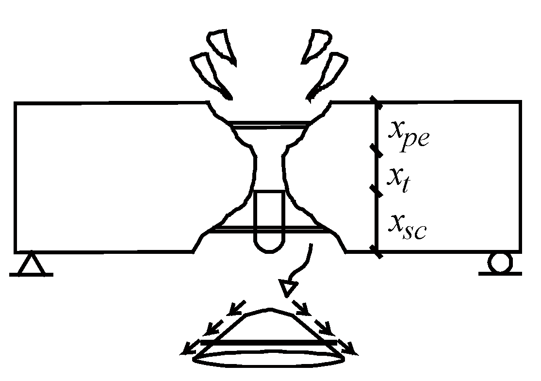
Figure 1. Scabbing-resistant energy (ESC).
Applsci 10 05481 g001
Figure 2. Stress flow on interface between scabbed concrete and slab.
Applsci 10 05481 g002
Figure 3. Scabbing theory [8].
Applsci 10 05481 g003
Figure 4. Definition of the radius of the contact area (act).
Applsci 10 05481 g004
Figure 5. Relation between distance (z) and penetration depth (xpe).
Applsci 10 05481 g005
Figure 6. Perforation definition in this paper.
Applsci 10 05481 g006
Figure 7. Ratio of tested-to-predicted scabbing depth.
Applsci 10 05481 g007
Figure 8. Ratio of tested penetration depth-to-scabbing depth.
Applsci 10 05481 g008
Figure 9. (a) Proposed formula; (b) modified National Defense Research Committee (NDRC); (c) Hughes formula; (d) Army Corps of Engineers (ACE) formula. Panel thickness (h) divided by predicted scabbing limit thickness (hsc).
Applsci 10 05481 g009
Figure 10. (a) Proposed formula; (b) modified NDRC; (c) Hughes formula; (d) ACE formula. Panel thickness (h) divided by predicted perforation limit thickness (hpf).
Applsci 10 05481 g010
Table 1. Number of specimens with scabbing failure.
Ratio RangeNumber of SpecimensAverage Ratio
Under 1190.85
Under 1.5431.05
Under 2521.16
Over 2293.14
Table 2. Accuracy of scabbing limit thickness formula.
FormulaScabbing Failure
(Predicted/Tested)
No Scabbing Failure
(Predicted/Tested)
Proposed100%
(75 of 75 specimens)
81%
(139 of 172 specimens)
Modified NDRC100%
(75 of 75 specimens)
66%
(113 of 172 specimens)
Hughes100%
(75 of 75 specimens)
43%
(74 of 172 specimens)
ACE100%
(75 of 75 specimens)
66%
(113 of 172 specimens)
Table 3. Accuracy of perforation limit thickness formula.
FormulaPerforation FailureNo Perforation Failure
Proposed63%
(41 of 65 specimens)
99%
(180 of 182 specimens)
Modified NDRC77%
(50 of 65 specimens)
93%
(170 of 182 specimens)
Hughes100%
(65 of 65 specimens)
67%
(125 of 182 specimens)
ACE88%
(57 of 65 specimens)
91%
(166 of 182 specimens)