Article

Analysis of Phase Noise in a Hybrid Photonic/Millimetre-Wave System for Single and Multi-Carrier Radio Applications

School of Electronic Engineering, Dublin City University, Glasnevin, Dublin 9, Ireland
*
Author to whom correspondence should be addressed.
Appl. Sci. 2020, 10(17), 5800; https://doi.org/10.3390/app10175800
Submission received: 17 July 2020 / Revised: 6 August 2020 / Accepted: 19 August 2020 / Published: 21 August 2020
(This article belongs to the Special Issue Photonic Technology in 5G)

Abstract

:
The future evolution of wireless networks, throughout the 5G era and beyond, will require the expansion and augmentation of millimetre-wave systems for both terrestrial and satellite communications. Photonic technologies offer a cost efficient and high bandwidth platform for millimetre-wave carrier generation and distribution, but can introduce high levels of phase noise through optical heterodyning, which is highly problematic for mobile signal waveforms. In this work, a detailed analytical model of a hybrid photonic/mm-wave system is developed and discussed. Through careful system design, the system is found to support both 5G compatible multi-carrier (OFDM) and single carrier (APSK) modulation at 60 GHz. APSK is found to offer higher tolerance mm-wave phase noise compared to OFDM, ultimately easing optical linewidth restrictions to ∼30 kHz. The model is extended to include a novel millimetre wave phase noise cancelling receiver, which is shown to significantly alleviate these restrictions even further—enabling phase noise free mm-wave operation for optical linewidths up to ∼2 MHz. Detailed analysis and discussion of this extended system lead to the establishment of a theoretical relationship between the mm-wave receiver design and the achievable system performance in terms of error vector magnitude (EVM). Excellent matching of the predicted theoretical with simulated performances is shown.

1. Introduction

Today’s internet users are exposed to a constant stream of newly developed advanced mobile applications. Unprecedented levels of device connectivity and the continual shift toward remote working are driving the demand for cloud-based services such as high definition video streaming and teleconferencing. As wireless communication systems evolve throughout the 5G era and beyond, they will be required to support futuristic and extremely data-hungry services, such as virtual reality (VR) and autonomous vehicles (AV). This incessant growth in required network capacity can only be catered for by the enhancement of fixed and wireless networks through the adoption of new communication techniques and technologies.
In recognition of the need for increased spectral usage, 5G new radio (NR) protocols have identified frequencies up to 52.6 GHz for use in its FR2 frequency band [1]. This paves the way for the introduction of millimetre-wave (mm-wave) communication technologies for high-speed mobile data transfer. For terrestrial systems, mm-wave transmission ranges are relatively short, but the expected proliferation of small cell antenna sites, and the ability to perform hybrid beam-forming of the mm-wave signal will make its use viable for high throughput applications [2]. Satellite broadband links already make use of mm-wave frequencies in the Ku (12–18 GHz) and Ka (26.5–40 GHz) bands, but in order for these links to complement future terrestrial mobile service delivery, further expansion of the V-band (40–75 GHz) and the W-band (75–110 GHz) will likely be required to deal with predicted demand [3].
The extent to which mm-wave communications can be leveraged for future wireless systems depends greatly on the ability to easily generate mm-wave frequency carriers. The difficulty and expense currently associated with generating high quality carriers in this frequency range, by purely electronic means, hinder the potential wide deployment of these systems. An alternative method for mm-wave generation is optical heterodyning, which involves the photo-mixing of two optical carriers, spaced by a mm-wave frequency, on a high speed photo diode (PD)—producing a beat term mm-wave carrier at the output of the PD. The relative ease of optical carrier generation, operation over a wide bandwidth/frequency range, inherent compatibility with optical distribution technologies, avoidance of costly high frequency electronic components, and the continued development of small form factor integrated microwave/mm-wave photonic components make heterodyning a highly promising contender for mm-wave systems, in the 5G era and beyond [4,5].
Optical heterodyning has long been proposed as a method for mm-wave and terahertz carrier generation [6,7], with many demonstrations showcasing its ability to form the basis for high bandwidth, high throughput wireless systems [8]. However, studies of the compatibility of such photonic systems with the modulation formats required for future mobile service delivery have been limited to date. Our own recent works have shown how mm-wave phase noise derived from the optical domain, through the heterodyne process, can severely degrade multi-carrier modulation (MCM) mobile formats [5,9,10]. In an effort to mitigate this system limitation, we recently proposed and experimentally demonstrated an analog noise-cancelling photonic/mm-wave system design, which enabled phase noise free reception of an MCM mobile signal at 61 GHz [11].
In this work, detailed analytical models of a hybrid photonic/mm-wave system, employing both a traditional stand-alone local oscillator (LO) based receiver, and the phase noise cancelling (PNC) receiver described in [11], are presented. The systems are evaluated and compared in terms of their ability to handle next generation multi-carrier orthogonal frequency division multiplexing (OFDM) and the single-carrier 32 amplitude phase shift keying (32-APSK) formats. For both systems, and both waveforms, the critical impact of the optical source linewidths (and resulting mm-wave phase noise) is investigated in terms of overall performance—revealing important system limitations in all cases. Furthermore, through theoretical analysis, PNC receiver design rules are established, allowing mm-wave system optimization for given optical linewidths, optical carrier and sideband frequency spacing and target performance (in terms of EVM or signal-to-noise ratio (SNR)).
The outline of the paper is as follows: Section 2 outlines the potential of photonic assisted mm-wave communications in a networking context and Section 3 discusses the waveforms which hold importance for these networking scenarios. Section 4.1 details the developed hybrid photonic/mm-wave platform and Section 5 provides an analysis of system performance. Finally, Section 6 concludes the work.

2. Millimetre-Wave Network Applications

Within the context of 5G communications and future mobile networking, the following two subsections outline two key applications which motivate the development and testing of the hybrid photonic/mm-wave system presented in this work.

2.1. Terrestrial

For next generation mobile networks, the application of mm-wave technologies can be considered, both for high bandwidth application specific scenarios (such as live high-definition video editing or AV data transfer) and wider-scale mobile service provisioning. Particularly in the latter case, mm-wave transmission and generation will be required to integrate seamlessly with radio-over-fibre (RoF) links, which transport data signals between a baseband unit (BBU), located at a central office (CO), and a remotely deployed remote radio head (RRH), from where the wireless signal is transmitted and received. These optical distribution links (known as fronthaul) are now critical radio access network (RAN) components, which must support future mobile network scaling, in terms of both data rate and the number of deployed RRHs. This network evolution will require a shift away from the currently deployed binary modulation based fronthaul, which uses the enhanced common public radio interface (eCPRI) protocol, to a more spectrally efficient and flexible scheme [12]. Within this context, many recent works have proposed the use of more advanced single and multi-carrier modulation formats (which can be broadly categorised as digital (D)-RoF and analog (A)-RoF, respectively) for fronthaul transmission [13,14,15].
The potential of RoF and other photonic technologies to enable the deployment of high throughput mm-wave communications has been noted by the research community. This has led to a major focus on the development of hybrid photonic/mm-wave systems [16,17,18], including those leveraging the heterodyne process [19,20,21].

2.2. Satellite

The rising demands for device connectivity and enhanced mobile broadband have led to somewhat of a resurgence in satellite communications. With the continued deployment of high throughput satellites (HTS), and the pursuit of terabit-scale network capacities [22], the potential for satellite technology to complement, and augment, terrestrial mobile networks (by providing robust 5G service delivery) has been widely recognised [23,24]. Indeed, the term ’Non Terrestrial Networks’ (NTN) is now used to refer to 5G communications, including satellites, unmanned aerial systems (UAVs) and high altitude platforms (HAPs), with ongoing standardization seeking to seamlessly integrate these facilities with the 5G eco-system [25,26]. In rural areas where fibre penetration may be low, mm-wave satellite links may be used to provide 5G data transport—effectively acting as a 5G RAN node in a hybrid satellite-terrestrial network [24], with the potential to provide front-haul and back-haul services. The convenient overlap between 5G NR’s FR2 and the Ka band strengthens the case for mm-wave service delivery through such a hybrid networking scheme [27].
With photonic technologies offering reduced size, weight and power consumption, and robustness to RF interference compared to conventional electronic components, it is no surprise that hybrid photonic/mm-wave systems have also been proposed for deployment in satellite communications systems [28].

3. Waveforms for Millimetre-Wave Mobile Communications

As well as defining initial frequency bands of operation, 5G NR also specifies the use of the OFDM waveform for system deployments, with increased signal bandwidths and subcarrier spacings compared to 4G long-term evolution (LTE). For operation in the FR2 band, ref. [1] defines OFDM bandwidths up to 400 MHz and subcarrier spacings of 60/120/240 kHz. In hybrid photonic/mm-wave systems using MCM schemes, such as OFDM, our previous work [5] has shown that the phase noise of the heterodyne mm-wave carrier relative to the subcarrier spacing/baud rate is of critical importance. This ultimately leads to the requirement for ultra-low linewidth optical sources in the sub-kHz to kHz range, greatly hindering the wide-scale deployment of such systems. Our recent work [11,29] has focused on developing phase noise robust photonic/mm-wave systems, which help to ease these laser linewidth restrictions and enable the use of lower cost commercially available devices—which typically exhibit a higher linewidth.
APSK is a highly popular modulation format for satellite communications. The single-carrier modulation format was first adopted for satellite digital TV through the Satellite Digital Video Broadcasting (DVB-S) open standards. Today, DVB-S2 (up to 32-APSK), and optional extension DVB-S2X (64/128/256-APSK) have been widely adopted to encapsulate satellite broadband traffic, including transmission in the Ka band [30]. DVB-S’ popularity stems from its relatively high spectral efficiency and inherent robustness against nonlinear distortion, which can be attributed to its unique APSK constellation. The ideal 32-APSK constellation (which is presented later in Section 4.2) consisting of three concentric rings is shown in Figure 3b. The absence of a wide range of symbol amplitudes results in a reduced peak-to-average power ratio (PAPR) compared to the equivalent quadrature amplitude modulation (QAM) constellation—making APSK more resilient to nonlinear distortions introduced by high-power amplifiers (HPAs). Furthermore, the ratio of the APSK ring radii can be varied in order to tailor the waveform PAPR for a given channel, at the cost of altering the Euclidean distance between constellation points.
It is worth noting that, although OFDM exhibits relatively high levels of PAPR, its advantages in terms of subcarrier flexibility, spectral efficiency and inherent compatibility with terrestrial broadband and 5G networks have led to its inclusion in discussion around next generation waveforms for satellite broadband applications [3,31,32]. Adaptations to OFDM’s basic form, in order to limit PAPR and out-of-band (OOB) emission, may be required for satellite communications [32], but its key potential benefits are clear; the provision of a ubiquitous 5G networking platform and the ease of interaction with terrestrial systems.
With the aims of demonstrating the proposed hybrid system’s relevance to the networking applications outlined in Section 2, and providing a comparative study of single-carrier and multi-carrier modulation performances in the presence of mm-wave phase in such a system, both 32-APSK and 32-QAM OFDM are applied in the simulation platform which is outlined in the following section.

4. Hybrid Photonic/Millimetre-Wave System and Simulation Details

4.1. System Simulation

The hybrid photonic/mm-wave platform is depicted in Figure 1. The system is simulated in Matlab and is designed to resemble the experimental setup presented in [11]. Table 1 gives the key simulation parameters. The optical portion of the system contains two optical sources that are simulated by way of the generation of two carriers separated by the mm-wave frequency (60 GHz), each with independently generated noise terms. The electric field associated with a simulated carrier is described using the general expression:
E ( t ) = 1 + n R I N · E 0 · exp ( j 2 π f c t + ϕ ( t ) ) .
where E 0 represents the optical field amplitude, f c is the carrier frequency and n R I N is the band-limited relative intensity noise (RIN), which is formulated as described in [5]. Moreover, ϕ ( t ) contains the phase noise of the optical carrier. Its discrete form is implemented by taking m samples (where m is also the length, in samples, of the data signal to be transmitted) of a uniformly Gaussian distributed noise vector with zero mean and unity variance, f ^ ( m ) , and performing a scaled running sum over the vector, such that the random walk phase noise at the l th time step is given by:
ϕ ( l ) = 2 π · L W o p t · t s m = 0 l f ^ ( m ) .
where L W o p t is the 3-dB optical linewidth and t s is the sampling period, which was 5 ps in this work. The optical sources shown in Figure 1 both produce an optical carrier as per Equation (1), with each being assigned the same levels of independently generated (i.e., un-correlated) RIN and phase noise. The frequencies of the carriers were set within the simulation spectral window (±100 GHz), to have a frequency separation of 60 GHz.
Partial single-sideband (SSB) modulation of one of the optical carriers with a real valued intermediate frequency (IF) OFDM/APSK signal is performed using a modelled Mach–Zehnder modulator (MZM), followed by an optical band-pass filter (OBPF), while the other carrier is unmodulated. The MZM is biased close to, but not on, the null point of its transfer characteristic. This provides optical field modulation, while allowing the optical carrier to remain relatively unsuppressed. Such operation is required by the PNC receiver stage, whose operation is described below. In practice, ideal optical SSB modulation is difficult to achieve at frequencies close to the carrier, if the carrier itself is to be maintained. This is replicated here by setting the OBPF (with passband of 5 GHz) such that the lower frequency sideband is suppressed by ∼25 dB relative to the upper sideband. All filtering in the simulated system is implemented using a Gaussian shaped profile applied in the frequency domain. The simulated spectra of the unmodulated and partial SSB modulated optical carriers are shown in Figure 2a,b, respectively. Figure 2a illustrates the Lorentzian-shaped spectral profile synonymous with optical carrier generation [33].
The optical carriers are combined and fed to a PIN photodetector with a bandwidth of 100 GHz and a shot and thermal noise as defined in [5]. Optical heterodyning of the modulated and unmodulated carriers takes place, producing an electrical signal with a strong carrier term at 60 GHz and information sideband signal at 62 GHz, as shown by the mm-wave spectrum in Figure 2c. Following V-band wave-guide filtering, the electrical signal can be directed to one of two simulated mm-wave receivers:
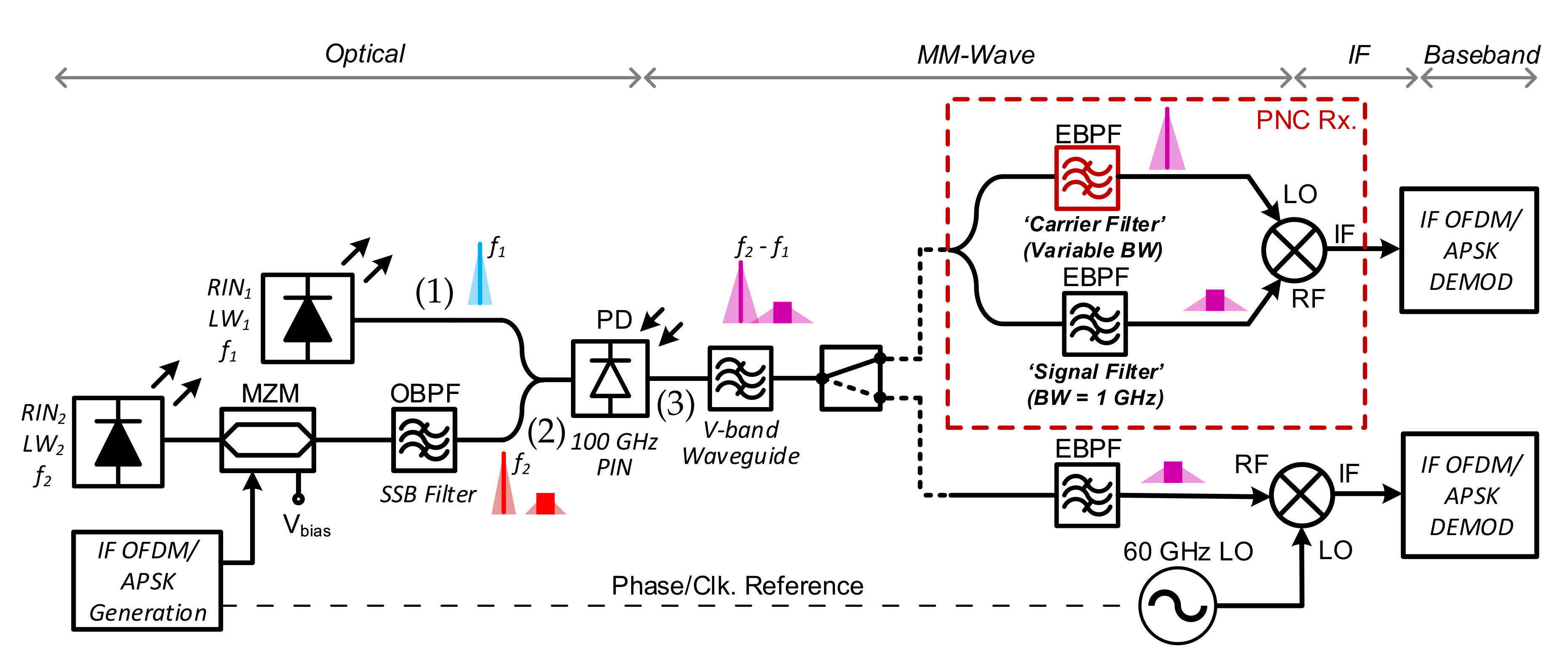
  • LO-based Receiver: A standard receiver structure consisting of a mm-wave mixer and local oscillator (LO) is depicted in the lower half of the receiver side in Figure 1. The incoming signal is passed through an electrical band-pass filter (EBPF), which serves to isolate the upper data sideband portion of the mm-wave spectrum, centred at 62 GHz. The filtered signal is mixed with a 60 GHz carrier generated by the receiver LO, which is phase locked to the transmitter side. The down-converted IF signal at 2 GHz is then passed to the IF OFDM/APSK demodulator.
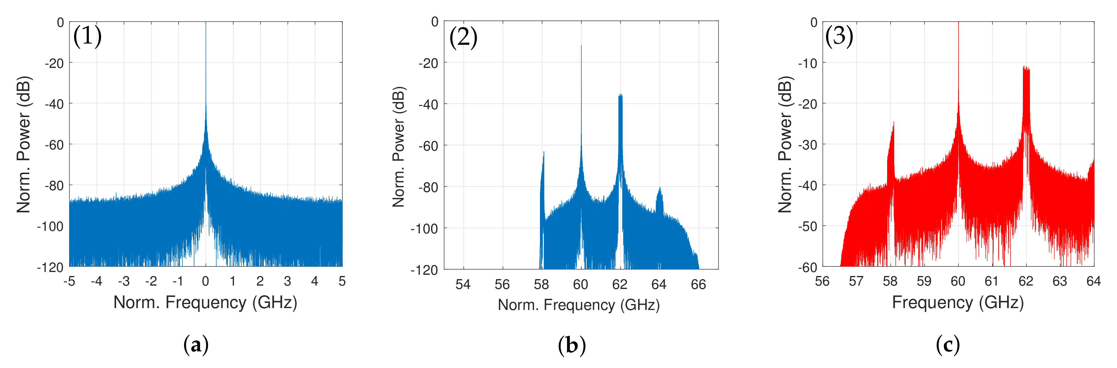
  • PNC Receiver: The analog phase noise cancelling mm-wave receiver architecture is outlined by a dotted red line in Figure 1. This architecture allows phase noise and frequency offset cancellation at the IF down-conversion stage without the requirement for a standalone receiver LO, and this is described in detail in [11]. After photo detection, the electrical spectrum shown in Figure 2c is split into two paths. The PNC receiver contains an EBPF in each path; a signal filter and a carrier filter, which are used to isolate the upper data sideband (at 62 GHz) and mm-wave carrier term (at 60 GHz), respectively (these terms are represented by the purple illustrative spectra in Figure 1). The filtered signal and carrier terms are then used as the ‘RF’ and ‘LO’ inputs to a mm-wave mixer, respectively. These filtered components exhibit matching phase noise as a result of being generated through the same photo-mixing process. This allows the filtered carrier term to be used as a phase noise correlated ‘LO’, which, when mixed with the signal term, produces an IF data signal (at 2 GHz) free from phase noise.
For both receiver stages, sharp band-pass filtering in the mm-wave domain is implemented in the model by using 10th order Gaussian shaped frequency domain filter profiles, as given by the function:
g ( f ) = exp ( f f o ) n 2 σ n .
where f o is the filter center frequency, 2 σ is the 3-dB bandwidth of the filter and n in the filter order.

4.2. Waveform Generation and Reception

Multi-carrier IFFT based OFDM generation is performed broadly in line with the 5G NR (3GPP Rel. 15) specifications for mm-wave communications. Overall, 800 active subcarriers modulated with 32-QAM and with a baud rate/frequency spacing of 244 kHz, are used to generate the ∼1 Gb/s OFDM signal. The first OFDM symbol is designated as a training symbol (TS). A cyclic prefix (CP) of 6.25% of the signal length is added after IFFT processing. Following parallel-to-serial operation, I/Q up-conversion of the baseband OFDM signal to 2 GHz, results in the real-valued IF OFDM spectrum are shown in Figure 3a. This transmit sequence is then over-sampled to match the global simulation sample rate.
At the IF OFDM demodulator, the IF signal produced at the output of the receivers described in Section 4.1 is re-sampled and digitally down-converted to baseband. CP removal precedes receiver FFT de-modulation. Channel estimation is then performed through comparison of the transmitted and received TS—facilitating single-tap frequency domain equalization (FDE). Finally, EVM is calculated for all received QAM symbols.
The 32-APSK ideal signal constellation is shown in Figure 3b. The 32 constellation points are arranged in three concentric circles which, in this case, are equidistant. Then, 32-APSK encoding of a random binary stream is performed at 200 MBaud, resulting in a total spectral bandwidth of 400 MHz (3-dB bandwidth = 200 MHz). I/Q up-conversion of the time domain signal results in the APSK spectrum shown in Figure 3c. At the receiver, the single-carrier IF APSK signal is re-sampled and down-converted through a digital I/Q mixer. Using the ideal 32-APSK constellation (Figure 3b) as a reference plane, a blind decision directed least mean squares (DD-LMS) algorithm is optionally implemented for phase estimation and correction of the received constellation.
Table 2 lists the main waveform parameters of interest for both APSK and OFDM signals.

5. Results and Discussion

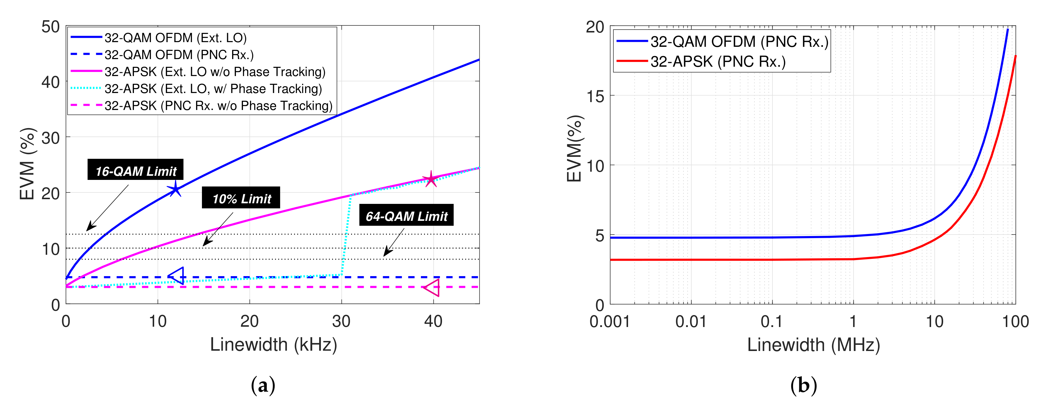
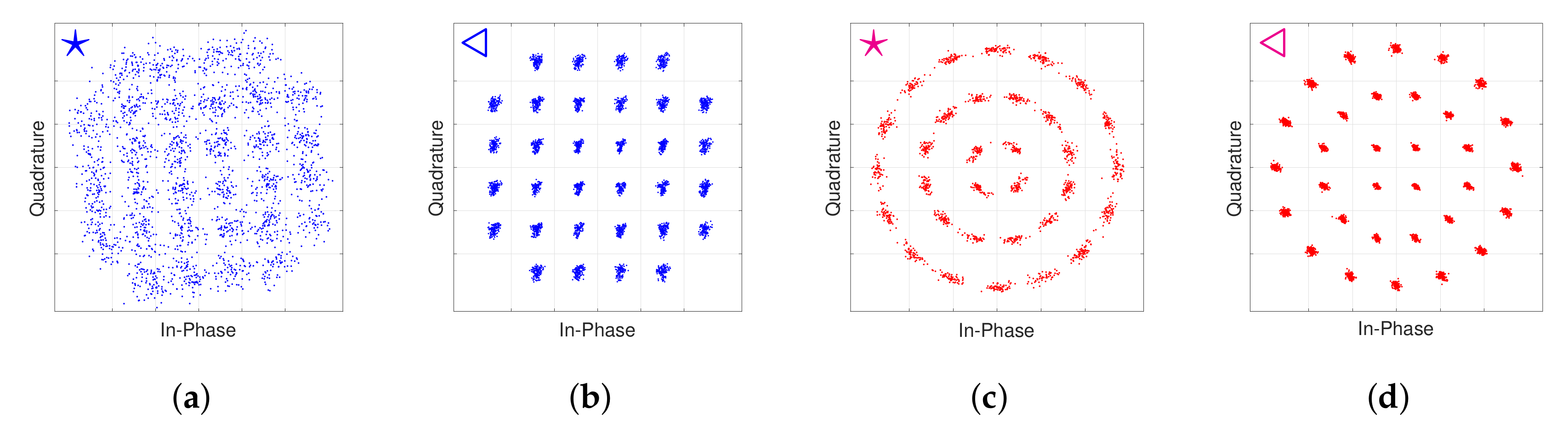
5.1. OFDM Versus APSK

The simulated photonic/mm-wave test-bed outlined in the previous section was firstly evaluated in terms of the tolerance of both waveforms to mm-wave phase noise produced through the heterodyne process. Figure 4a shows the system performance, in terms of EVM, for both mm-wave receivers, as the linewidths of the optical sources were varied. It should be noted that the independent optical phase noise terms are set to have the same linewidth value. After the photo-mixing of these two carriers at the PD, the resultant 60 GHz mm-wave carrier and mm-wave data signal will possess a phase noise, characterized by a linewidth value which is the summation of the optical linewidths. In the case where the standard external LO based receiver is used, Figure 4a shows that OFDM reception is highly sensitive to increased optical linewidth. This is as a direct result of OFDM’s MCM FFT-based implementation, which requires strict alignment of orthogonal subcarriers in the frequency domain, as discussed in [5]. Here, the perturbation of the 244 kHz bandwidth data-carrying subcarriers through the introduction of phase noise leads to severe degradation, where EVMs above 10% can be observed for optical source linewidths of just a few kHz. It should be noted that 5G NR specifies an EVM limit of 8% and 12.5% for 64-QAM and 16-QAM, respectively, but does not specify for 32-QAM to date. An EVM target of 10% is discussed in this work as it is sufficient to obtain a bit error rate (BER) below the 7% forward error correction (FEC) limit of 3.8 × 10 3 . Figure 5a shows the received 32-QAM OFDM constellation (EVM = 21%), where optical source linewidths are both set to 12 kHz. For all OFDM results, channel estimation, as well as single-tap frequency domain equalization, was performed.
For the same external LO-based receiver, the figure shows that APSK exhibits a higher tolerance to phase noise compared to OFDM. APSK’s single-carrier implementation means that the information to be transmitted is spread across the entire APSK signal bandwidth (400 MHz). This effectively lowers the relative impact of a given level of mm-wave phase noise, compared to that experienced by a single OFDM subcarrier (244 kHz in this case). However, the results show that the level of performance improvement achieved by using APSK does not depend exclusively on the ratio of carrier modulation bandwidth to phase noise, but also on the application of receiver phase error correction. The cyan colored curve in Figure 4a represents the performance of APSK, where a blind least mean square (LMS) algorithm is used to estimate and correct phase offsets in the received constellation. Compared to the case where no phase tracking is applied (pink curve), a much improved performance, close to the system error floor, can be observed for optical source linewidth values up to 30 kHz—equating to 60 kHz of mm-wave phase noise. For higher linewidth values, the greater levels of phase noise variance become impossible to track, and this leads to the convergence of the APSK curves in the figure. Figure 5c shows the received 32-APSK signal in this case, where the optical linewidths are set at 40 kHz. It is possible that the inclusion of more advanced phase correction techniques [34] may help to sustain acceptable APSK performance beyond the 30 kHz limitation shown in Figure 4a. Nevertheless, for APSK baud rates around 200 MBaud, the results show that laser sources exhibiting linewidths in the order of 10’s kHz will be required for heterodyne operation, with a standard mm-wave receiver architecture.
When the PNC receiving architecture is used, the SSB information is down-converted to the IF stage by the carrier×carrier term which is isolated by the ’Carrier Filter’ highlighted in Figure 1. As discussed, the effect of this is to enable the cancellation of any phase noise (and any frequency offsets within the bandwidth of the filter) arising from the interaction of the optical carriers, via the heterodyne process. In this case, Figure 4a shows performances at the system error floor (i.e., performances attained for linewidth values of 0 kHz) for both APSK (EVM = 3.5%) and OFDM (EVM = 5%) modulation, for all linewidth values. The difference in optimum performance EVMs for both formats is a consequence of the relative impact of system intensity noise (RIN, PD shot noise and thermal noise) on APSK and OFDM, whose PAPRs are 1.79 dB and 12.46 dB, respectively—highlighting one of the major drawbacks of conventional OFDM. Corresponding phase noise free 32-QAM OFDM and 32-APSK constellations can be observed in Figure 5b,d, respectively.
Figure 4b shows the performances of both OFDM and APSK, where the PNC receiver is enabled and optical linewidth values are swept over a broad range. EVMs corresponding to the optimum performance for both modulation formats are apparent for optical source linewidth values up to about 3 MHz, after which the received signal deteriorates.
The performance limitation evident in Figure 4b stems from the fact that the PNC receiver does not enable perfect phase noise cancellation in cases where the mm-wave carrier spectral profile is significantly band-limited by the PNC’s carrier filter. The phase noise contained in the mm-wave carrier term can be thought of as ’information’ required for analog noise cancellation at the mixing stage. In cases where the carrier filter bandwidth is large relative to the spectral profile of the mm-wave carrier, almost all of the carrier’s Lorentzian-shaped phase noise spectral component passes to the IF mixer and is used to cancel the equivalent component in the information signal. In cases where the filter bandwidth is small relative to the carrier’s spectral width, only partial phase noise cancellation can be performed, as the mm-wave carrier has been stripped of some of its phase noise detail, due to band-limiting. It follows that the performance of the system is proportional to the level of phase noise cancellation which can be performed, and hence the ratio of filter bandwidth to generated mm-wave phase noise. So, intuitively, the SNR of the received signal can be maximised when full phase noise cancellation is permitted by appropriate filtering. This points toward a relationship between the received signal SNR, carrier filter bandwidth and carrier linewidth, which is explored in the following section.

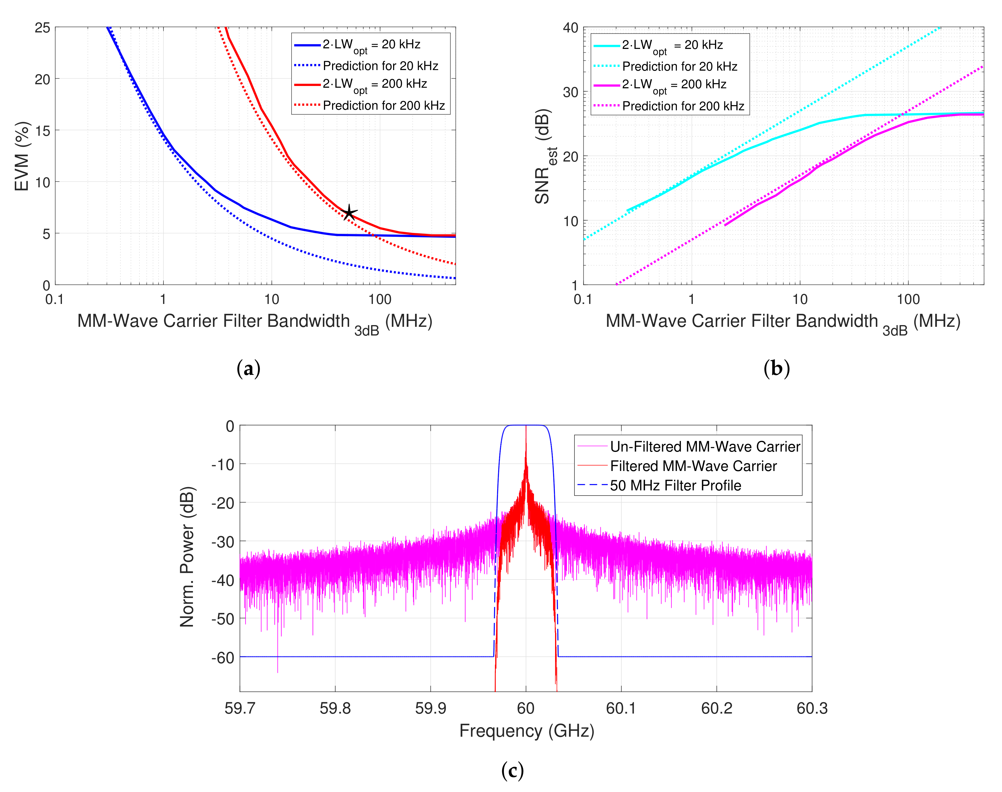
5.2. Impact of PNC Receiver Design

Consider an ideal implementation of the PNC receiver which comprises an ideal carrier filter, with bandwidth 2 B . This filter is used to isolate the mm-wave carrier generated through the heterodyne process, and whose phase noise is characterized by a 3-dB linewidth value L W e l e c . SNR, arising from the presence of phase noise only, can be approximated (conservatively), as follows (see Appendix A):
SNR 2 B L W e l e c ,
It should be noted that this relationship only holds when the PNC’s signal filter bandwidth is sufficient to allow the information signal and associated phase noise component to pass without curtailment. Here, an SNR of 1 indicates that the filter bandwidth is equal to the 3-dB linewidth of the mm-wave carrier component. Practically speaking, this scenario equates to the case where the mm-wave carrier spectrum is band-limited, such that only half of its spectral power can be used for the phase noise cancellation step at the IF down-conversion stage. Considering the high-order Gaussian filter design used in this work (with a bandwidth of F 3 d B ), and the fact that the generated mm-wave carrier linewidth is equal to the summation of the independent optical carrier linewidths (given by the term L W o p t in Equation (2)), the above relationship can be extended as follows:
SNR F 3 d B 2 × L W o p t ,
Given that SNR is related to the root mean square EVM performance metric through the following equation:
SNR = 1 EVM 2 ,
an approximate expression for EVM can also be given as:
EVM ( % ) 2 × L W o p t F 3 d B · 100 .
In order to minimize EVM, the expression (7) indicates that F 3 d B should be as large as possible. However, as this filter is required to isolate the mm-wave carrier term only, a large value of F 3 d B effectively precludes the use of frequencies around the carrier (i.e., within the carrier filter pass-band) for data modulation. In other words, relatively large IFs must be selected for optical modulation if F 3 d B is large—leading to a wider frequency separation between carrier and signal (sideband) terms in both the optical and mm-wave domains. Considering that the PNC based system which hinges on the co-transmission of both the carrier and signal sideband terms, the requirement for a large frequency separation between these terms is clearly sub-optimal from the perspective of spectral usage. A significant motivating factor for reducing the frequency separation between these components is the ease of compatibility with integrated photonic beam-forming networks (e.g., [35]), whose complexity can be reduced, and achievable mm-wave beam steering angle increased, with narrow-band operation [36].
In essence, when it comes to determining the filter criteria, a trade-off exists between performance optimization through wide-band filtering of the mm-wave carrier, and the efficient use of mm-wave spectrum.
Figure 6a shows the performance of the proposed system using the PNC receiver with OFDM modulation, where the bandwidth of the mm-wave carrier filter is varied from 0.1–500 MHz. For optical linewidth values of 10 and 100 kHz (which equates to mm-wave carrier linewidths/phase-noise of 20 kHz (blue curve) and 200 kHz (red curve), respectively), performances improve with increased carrier filter bandwidth, until the performance floor is reached. These scenarios can be observed for bandwidth values of around 30 and 200 MHz, for the blue and red curves. Performances below 10% EVM can be guaranteed for reduced filter bandwidth values of 2.5 and 20 MHz, respectively.
The accompanying dotted lines in the figure are the predicted performance curves given by expression (7). The figure shows that this conservative estimate for the achievable system SNR exhibits good matching with the simulated system which also incorporates the intensity noise processes (RIN, shot noise, thermal noise), which are inherent to optical heterodyne implementations. The theoretical and simulated curves diverge as the system performance plots begin to reach the performance floor (evident due to the inclusion of intensity noise). Nevertheless, the results show that, with prior knowledge of the optical source linewidths (which would typically be known), the expression given in (7) can be used to indicate the minimum required carrier filter bandwidth for a target EVM, for the system described.
Using the expression given by (6), this analysis can be extended to the system electrical SNR. Figure 6b shows how the received SNR varies with carrier filter bandwidth—for the same linewidth conditions given above. The dotted lines in the figure represent the predicted variance in SNR given by the expression (5). As expected, the prediction shows good alignment with the simulated results for lower filter bandwidth values. For example, given two optical sources with 100 kHz linewidth each and a target SNR of 20 dB, the predicted SNR curve (cyan dotted line) indicates that a minimum carrier filter 3-dB bandwidth of 2 MHz is required. This is matched well by the corresponding simulated curve which, for higher filter bandwidths, converges to the maximum achievable electrical SNR value for the given system conditions. In general, for the cases presented, the theoretical plots indicate that for a target electrical SNR value of ≥100 (equating to ≤10% EVM), the mm-wave carrier filter must have a 3-dB bandwidth which exceeds the combined optical linewidth value by a factor of at least 100.
Figure 6c shows spectral profiles of the 60 GHz heterodyne generated carrier before and after filtering by the PNC receiver’s carrier filter. The profile of this mm-wave carrier filter is also shown to be superimposed on the figure. In this case, F 3 d B was set to 50 MHz and L W o p t was set to 10 kHz—corresponding to the system performance point denoted with a star in Figure 6a.

6. Conclusions

The continued evolution of mobile broadband networks relies on the exploitation of new spectra, and the creation of a robust service delivery platform, incorporating both terrestrial and satellite technologies. This points toward the likely proliferation of mm-wave frequency transmission systems for high throughout applications and use within 5G distribution networks, particularly considering recent efforts in standardization. The generation, processing and distribution of mm-wave signals by photonic means offer a flexible and high-bandwidth solution compared to electronic technologies. Inherent compatibility with optical distribution networks and the continued advancement of chip-scale photonic circuits make the convergence of mm-wave and optical communications technologies inevitable. Through the development and evaluation of a detailed model of a hybrid photonic/mm-wave communications system employing optical heterodyning, this work has shown how such systems can be used to deliver the single and multi-carrier waveforms synonymous with both satellite and terrestrial broadband communications.
Overall, due to its single-carrier implementation, the APSK format exhibits superior tolerance to both intensity noise and mm-wave phase noise generated through the optical heterodyne process, albeit without offering the subcarrier flexibility and single-tap frequency domain equalization provided by OFDM. The 5G compatible multi-carrier OFDM signal performs poorly in the presence of phase noise, due to the relatively low subcarrier spacing, imposing severe limitations on the optical source linewidths, ranging from kHz to sub-kHz levels.
Extending the model to include an analog phase noise cancellation stage at the receiver reveals that these optical linewidth restrictions can be significantly alleviated for both waveforms. The evaluated system is shown to enable phase noise free operation for optical linewidth values up to ∼2 MHz, showcasing its potential to provide an efficient platform for photonic/mm-wave system deployment by enabling the use widely available optical sources, such as distributed feedback (DFB) lasers. This relaxed upper bound on optical linewidth is found to be determined by the receiver’s carrier filter design. The related analysis leads to a direct relationship between the filter’s bandwidth and the achievable system performance (in terms of EVM and SNR) in the presence of phase noise, with good matching exhibited for both theoretically predicted and simulated performances. This relationship serves as a critical design rule for mm-wave receiver optimization; by indicating the minimum required filter bandwidth for a target SNR/EVM and, in turn, facilitating optimum spectral usage.
Ultimately, through the significant alleviation of optical linewidth requirements—enabling the use of cost-efficient laser diodes—and an optimized receiver design, the hybrid photonic/mm-wave system discussed and analyzed in the work has the potential to provide a flexible, low-cost and bandwidth efficient solution for next generation mm-wave applications, employing both single and multi-carrier transmission techniques.

Author Contributions

Conceptualization, C.B.; methodology, D.D. and C.B.; software, D.D., A.D. and C.B.; validation, D.D. and C.B.; formal analysis, D.D., C.B. and S.O.; investigation, D.D. and C.B.; writing—original draft preparation, D.D. and C.B.; writing—review and editing, D.D., S.O. and A.D.;g supervision, C.B.; project administration, C.B.; funding acquisition, C.B. All authors have read and agreed to the published version of the manuscript.

Funding

This research was funded by Science Foundation Ireland under grant number 18/SIRG/5579.

Conflicts of Interest

The authors declare no conflict of interest.

Appendix A

Assume that a carrier containing phase noise generated through an optical heterodyne process can be approximated in the spectral domain by a Lorentzian shaped profile. The expression for a Lorentzian distribution is given as:
L ( f ) = 1 γ γ 2 ( f f 0 ) + γ 2 ,
where f 0 is the frequency offset and γ specifies half width at half maximum (and 2 γ is the 3-dB linewidth of the carrier source with phase noise). Setting f 0 = 0 , γ = 1 and normalizing f with respect to γ for a standard distribution yields:
L ( f ) = 1 1 + f 2 ,
Integrating this expression reveals the power of the normalized Lorentzian distribution:
1 1 + f 2 d f = arctan ( ) arctan ( ) = π 2 π 2 = π .
Consider a band-limited distribution with frequency bounds B f B . The single-sided power of the band-limited distribution can be expressed as:
0 B 1 1 + f 2 d f = arctan ( B ) arctan ( 0 ) = arctan ( B ) ,
For the purposes of enabling noise cancellation across the full spectral range of a secondary signal, using band-pass filtering of a carrier containing phase noise (as discussed in Section 5.2), an SNR metric can be defined, where the signal component is the power of the distribution retained by band-limiting, and the noise component is the power of the distribution lost by band-limiting. This can be expressed as follows:
P s i g = 2 · arctan ( B ) and P n o i s e = π 2 · arctan ( B ) ,
and hence,
SNR = P s i g P n o i s e = 2 · arctan ( B ) π 2 · arctan ( B ) ,
Since f is normalized to γ , and B ϵ f , the above expression can be generalized to:
SNR = 2 · arctan ( B γ ) π 2 · arctan ( B γ ) ,
It is clear from the above expression that the SNR metric varies in proportion to the ratio of B, the single sided band-limit, to γ , half the linewidth. Setting B = γ —which is equivalent to setting the pass-band of an ideal band-limiting filter ( 2 B ) equal to the 3-dB linewidth of the Lorentzian ( 2 γ )—gives
SNR = 2 · arctan ( 1 ) π 2 · arctan ( 1 ) = 1 ,
and so for B γ and B γ an approximation of the SNR metric is given by:
SNR B γ .
For B γ , which describes most practical scenarios, the following approximation can be made:
arctan B γ π 2 1 B / γ ,
which allows the Equation (A7) to be approximated to:
SNR B γ · π 2 1 .
Compared to this approximation, the expression given in (A9) can be viewed as a conservative estimation of the achievable system SNR, for given linewidth and ideal filter pass-band values.

References

  1. 3GPP. 3GPP TR 21.915 V15.0.0; Technical Report; ETSI: Valbonne, France, 2019; p. 25. [Google Scholar]
  2. Wei, L.; Hu, R.Q.; Qian, Y.; Wu, G. Key elements to enable millimeter wave communications for 5G wireless systems. IEEE Wirel. Commun. 2014, 21, 136–143. [Google Scholar]
  3. De Sanctis, M.; Cianca, E.; Rossi, T.; Sacchi, C.; Mucchi, L.; Prasad, R. Waveform design solutions for EHF broadband satellite communications. IEEE Commun. Mag. 2015, 53, 18–23. [Google Scholar] [CrossRef]
  4. Alavi, S.; Soltanian, M.; Amiri, I.; Khalily, M.; Supa’at, A.; Ahmad, H. Towards 5G: A Photonic Based Millimeter Wave Signal Generation for Applying in 5G Access Fronthaul. Sci. Rep. 2016, 6, 2045–2322. [Google Scholar] [CrossRef] [PubMed] [Green Version]
  5. Browning, C.; Elwan, H.H.; Martin, E.P.; O’Duill, S.; Poette, J.; Sheridan, P.; Farhang, A.; Cabon, B.; Barry, L.P. Gain-Switched Optical Frequency Combs for Future Mobile Radio-Over-Fiber Millimeter-Wave Systems. J. Light. Technol. 2018, 36, 4602–4610. [Google Scholar] [CrossRef]
  6. Stohr, A.; Heinzelmann, R.; Malcoci, A.; Jager, D. Optical heterodyne millimeter-wave generation using 1.55-/spl mu/m traveling-wave photodetectors. IEEE Trans. Microw. Theory Tech. 2001, 49, 1926–1933. [Google Scholar] [CrossRef]
  7. Shams, H.; Fice, M.J.; Balakier, K.; Renaud, C.C.; van Dijk, F.; Seeds, A.J. Photonic generation for multichannel THz wireless communication. Opt. Express 2014, 22, 23465–23472. [Google Scholar] [CrossRef] [PubMed]
  8. Puerta, R.; Yu, J.; Li, X.; Xu, Y.; Vegas Olmos, J.J.; Tafur Monroy, I. Single-Carrier Dual-Polarization 328-Gb/s Wireless Transmission in a D-Band Millimeter Wave 2 × 2 MU-MIMO Radio-Over-Fiber System. J. Light. Technol. 2018, 36, 587–593. [Google Scholar] [CrossRef]
  9. Delmade, A.; Verolet, T.; Browning, C.; Lin, Y.; Aubin, G.; Lelarge, F.; Ramdane, A.; Barry, L.P. Quantum Dash Passively Mode Locked Laser for Optical Heterodyne Millimeter-Wave Analog Radio-over-Fiber Fronthaul Systems. In Proceedings of the Optical Fiber Communication Conference (OFC) 2020, San Diego, CA, USA, 8–12 March 2020; Optical Society of America: Washington, DC, USA, 2020; p. 2. [Google Scholar] [CrossRef]
  10. Browning, C.; Martin, E.P.; Farhang, A.; Barry, L.P. 60 GHz 5G Radio-Over-Fiber Using UF-OFDM With Optical Heterodyning. IEEE Photonics Technol. Lett. 2017, 29, 2059–2062. [Google Scholar] [CrossRef] [Green Version]
  11. Browning, C.; Delmade, A.; Lin, Y.; Poette, J.; Elwan, H.H.; Barry, L. Phase Noise Robust Optical Heterodyne System for Reduced Complexity Millimeter-Wave Analog Radio-over-Fibre. In Proceedings of the European Conference on Optical Communication, Dublin, Ireland, 22–26 September 2019. [Google Scholar]
  12. Gomes, N.J.; Assimakopoulos, P.; Al-Hares, M.K.; Habib, U.; Noor, S. The new flexible mobile fronthaul: Digital or analog, or both? In Proceedings of the 18th International Conference on Transparent Optical Networks (ICTON), Trento, Italy, 10–14 July 2016; pp. 1–4. [Google Scholar]
  13. Breyne, L.; Torfs, G.; Yin, X.; Demeester, P.; Bauwelinck, J. Comparison Between Analog Radio-Over-Fiber and Sigma Delta Modulated Radio-Over-Fiber. IEEE Photonics Technol. Lett. 2017, 29, 1808–1811. [Google Scholar] [CrossRef] [Green Version]
  14. Li, W.; Chen, A.; Li, T.; Penty, R.V.; White, I.H.; Wang, X. Novel Digital Radio Over Fiber (DRoF) System With Data Compression for Neutral-Host Fronthaul Applications. IEEE Access 2020, 8, 40680–40691. [Google Scholar] [CrossRef]
  15. Delmade, A.; Browning, C.; Farhang, A.; Marchetti, N.; Doyle, L.; Koilpillai, R.; Barry, L.; Venkitesh, D. Performance Analysis of Analog IF Over Fiber Fronthaul Link With 4G and 5G Coexistence. J. Opt. Commun. Netw. 2018, 10, 174–182. [Google Scholar] [CrossRef]
  16. Ruggeri, E.; Tsakyridis, A.; Vagionas, C.; Leiba, Y.; Kalfas, G.; Pleros, N.; Miliou, A. Multi-user V-band uplink using a massive MIMO antenna and a fiber-wireless IFoF fronthaul for 5G mmWave small-cells. J. Light. Technol. 2020. [Google Scholar] [CrossRef]
  17. Morant, M.; Trinidad, A.; Tangdiongga, E.; Koonen, T.; Llorente, R. Experimental Demonstration of mm-Wave 5G NR Photonic Beamforming Based on ORRs and Multicore Fiber. IEEE Trans. Microw. Theory Tech. 2019, 67, 2928–2935. [Google Scholar] [CrossRef]
  18. Kanno, A.; Dat, P.T.; Yamamoto, N.; Kawanishi, T. Millimeter-Wave Radio-Over-Fiber Network for Linear Cell Systems. J. Light. Technol. 2018, 36, 533–540. [Google Scholar] [CrossRef]
  19. Kaszubowska-Anandarajah, A.; Delmade, A.; Martin, E.; Anandarajah, P.; Barry, L.; Browning, C. Bidirectional fiber transmission of mmW signals using remote downconversion and wavelength reuse. In Proceedings of the Conference on Lasers and Electro-Optics, San Jose, CA, USA, 5–10 May 2019; Optical Society of America: Washington, DC, USA, 2019; p. 4. [Google Scholar]
  20. Carpintero, G.; Balakier, K.; Yang, Z.; Guzman, R.C.; Corradi, A.; Jimenez, A.; Kervella, G.; Fice, M.J.; Lamponi, M.; Chitoui, M.; et al. Microwave Photonic Integrated Circuits for Millimeter-Wave Wireless Communications. J. Light. Technol. 2014, 32, 3495–3501. [Google Scholar] [CrossRef]
  21. Li, X.; Yu, J. Generation and Heterodyne Detection of >100-Gb/s Q -Band PDM-64QAM mm-Wave Signal. IEEE Photonics Technol. Lett. 2017, 29, 27–30. [Google Scholar] [CrossRef]
  22. Beidas, B.F. Radio-Frequency Impairments Compensation in Ultra High-Throughput Satellite Systems. IEEE Trans. Commun. 2019, 67, 6025–6038. [Google Scholar] [CrossRef]
  23. Giambene, G.; Kota, S.; Pillai, P. Satellite-5G Integration: A Network Perspective. IEEE Netw. 2018, 32, 25–31. [Google Scholar] [CrossRef]
  24. Jia, M.; Gu, X.; Guo, Q.; Xiang, W.; Zhang, N. Broadband Hybrid Satellite-Terrestrial Communication Systems Based on Cognitive Radio toward 5G. IEEE Wirel. Commun. 2016, 23, 96–106. [Google Scholar] [CrossRef]
  25. Kodheli, O.; Lagunas, E.; Maturo, N.; Sharma, S.K.; Shankar, B.; Montoya, J.F.M.; Duncan, J.C.M.; Spano, D.; Chatzinotas, S.; Kisseleff, S.; et al. Satellite Communications in the New Space Era: A Survey and Future Challenges. arXiv 2020, arXiv:eess.SP/2002.08811. [Google Scholar]
  26. Bacco, M.; Davoli, F.; Giambene, G.; Gotta, A.; Luglio, M.; Marchese, M.; Patrone, F.; Roseti, C. Networking Challenges for Non-Terrestrial Networks Exploitation in 5G. In Proceedings of the IEEE 2nd 5G World Forum (5GWF), Dresden, Germany, 30 September–2 October 2019; pp. 623–628. [Google Scholar]
  27. Arapoglou, P.D.M.; Cioni, S.; Re, E.; Ginesi, A. Direct Access to 5G New Radio User Equipment from NGSO Satellites in Millimeter Waves. arXiv 2020, arXiv:abs/2003.11078. [Google Scholar]
  28. Pan, S.; Zhu, D.; Liu, S.; Xu, K.; Dai, Y.; Wang, T.; Liu, J.; Zhu, N.; Xue, Y.; Liu, N. Satellite Payloads Pay Off. IEEE Microw. Mag. 2015, 16, 61–73. [Google Scholar] [CrossRef]
  29. Delmade, A.; Browning, C.; Farhang, A.; Koilpillai, R.D.; Venkitesh, D.; Barry, L.P. OFDM Baud Rate Limitations in an Optical Heterodyne Analog Fronthaul Link using Unlocked Fibre Lasers. In Proceedings of the International Topical Meeting on Microwave Photonics (MWP), Ottawa, ON, Canada, 7–10 October 2019; pp. 1–4. [Google Scholar]
  30. Arapoglou, P.D.; Ginesi, A.; Cioni, S.; Erl, S.; Clazzer, F.; Andrenacci, S.; Vanelli-Coralli, A. DVB-S2X-enabled precoding for high throughput satellite systems. Int. J. Satell. Commun. Netw. 2016, 34, 439–455. [Google Scholar] [CrossRef] [Green Version]
  31. Beidas, B.F.; Iyer Seshadri, R. OFDM-Like Signaling for Broadband Satellite Applications: Analysis and Advanced Compensation. IEEE Trans. Commun. 2017, 65, 4433–4445. [Google Scholar] [CrossRef]
  32. Guidotti, A.; Vanelli-Coralli, A.; Conti, M.; Andrenacci, S.; Chatzinotas, S.; Maturo, N.; Evans, B.; Awoseyila, A.; Ugolini, A.; Foggi, T.; et al. Architectures and Key Technical Challenges for 5G Systems Incorporating Satellites. IEEE Trans. Veh. Technol. 2019, 68, 2624–2639. [Google Scholar] [CrossRef] [Green Version]
  33. Hinkley, E.D.; Freed, C. Direct Observation of the Lorentzian Line Shape as Limited by Quantum Phase Noise in a Laser above Threshold. Phys. Rev. Lett. 1969, 23, 277–280. [Google Scholar] [CrossRef]
  34. Colavolpe, G.; Barbieri, A.; Caire, G. Algorithms for iterative decoding in the presence of strong phase noise. IEEE J. Sel. Areas Commun. 2005, 23, 1748–1757. [Google Scholar] [CrossRef]
  35. Grootjans, R.; Roeloffzen, C.; Taddei, C.; Hoekman, M.; Wevers, L.; Visscher, I.; Kapteijn, P.; Geskus, D.; Alippi, A.; Dekker, R.; et al. Broadband Continuously Tuneable Delay Microwave Photonic Beamformer for Phased Array Antennas. In Proceedings of the 49th European Microwave Conference (EuMC), Paris, France, 1–3 October 2019; pp. 812–815. [Google Scholar]
  36. Cao, Z.; Ma, Q.; Smolders, A.B.; Jiao, Y.; Wale, M.J.; Oh, C.W.; Wu, H.; Koonen, A.M.J. Advanced Integration Techniques on Broadband Millimeter-Wave Beam Steering for 5G Wireless Networks and Beyond. IEEE J. Quantum Electron. 2016, 52, 1–20. [Google Scholar] [CrossRef]
Figure 1. Simulated hybrid photonic/mm-wave system setup diagram, including the phase noise cancelling analog receiver architecture.
Applsci 10 05800 g001
Figure 2. Simulated (a) Unmodulated optical carrier, (b) partial SSB modulated optical carrier and (c) mm-wave spectrum after photo-detection. Numbering corresponds to measurement points in Figure 2.
Applsci 10 05800 g002
Figure 3. (a) IF 200 MHz bandwidth 32-QAM OFDM spectrum, (b) Ideal 32-APSK constellation diagram and (c) IF 200 MBaud 32-APSK spectrum.
Applsci 10 05800 g003
Figure 4. (a) Performance of OFDM and APSK with optical source linewidth variation, with LO based and PNC receivers, and (b) APSK and OFDM performance of a wider range of optical source linewidths, where the PNC receiver is engaged.
Applsci 10 05800 g004
Figure 5. Received OFDM constellations with the (a) external LO based receiver and (b) PNC receiver when the optical linewidths are set to 12 kHz; and received APSK constellations with the (c) external LO based receiver and (d) PNC receiver when the optical linewidths are set to 40 kHz.
Applsci 10 05800 g005
Figure 6. Simulated system and theoretical predicted performance for varying mm-wave carrier filter bandwidths in terms of (a) EVM and (b) SNR, and (c) mm-wave spectral profiles of the un-filtered and filtered heterodyne mm-wave carrier, and PNC carrier band-pass filter.
Applsci 10 05800 g006
Table 1. Simulation Parameters.
S.No.PropertyValue
1.mmWave Carrier Frequency60 GHz
2.Intermediate Frequency2 GHz
3.Optical LinewidthVariable
4.RIN−140 dB/Hz
5.Carrier Frequency Offset0 Hz
6.System Sample Rate200 GSa/s
Table 2. Waveform Parameters.
S.No.PropertyAPSKOFDM
1.Total Data Rate1 Gb/s0.98 Gb/s
2.Bandwidth200 MHz (3-dB)195.2 MHz
3.Modulation Order3232
4.Phase Tracking/EQLMSSingle-Tap FDE
5.No. Subcarriers-800
6.FFT Size-1024
7.Subcarrier Spacing-244 kHz
8.CP-6.25%

