Numerical Simulation and Design of a High-Temperature, High-Pressure Fluid Transport Pipe


1
Safety System R&D Group, Korea Institute of Industrial Technology, Cheonan-si 31056, Chungcheongnam-do, Korea
2
Korea Institute of Industrial Technology, 320 Techno sunhwan-ro, Yuga-myeon, Daegu 42994, Dalseong-gun, Korea
3
School of Mechatronics Engineering, Korea University of Technology & Education, 600, Chungjeol-ro, Byeongcheon-myeon, Dongnam-gu, Cheonan-si 31253, Chungcheongnam-do, Korea
*
Author to whom correspondence should be addressed.
Appl. Sci. 2020, 10(17), 5890; https://doi.org/10.3390/app10175890
Submission received: 20 July 2020
/
Revised: 13 August 2020
/
Accepted: 18 August 2020
/
Published: 25 August 2020
(This article belongs to the Special Issue Reliability of Materials and the Systems)
Abstract
:When designing a hand caliber with a high-temperature, high-pressure internal fluid transport pipe, reliability, safe use, and performance must be considered. Reliability refers to the stress caused by thermo-mechanical load; safe use refers to the low-temperature burns that might occur upon contact, and high-temperature burns caused by gas leakage occurring in the cylinder gap; and performance refers to projectile velocity. In this study, numerical simulation methods for heat transfer, structure analysis, and gas leakage are proposed so that solutions can be designed to account for the above three criteria. Furthermore, a hand-caliber design guide is presented. For heat transfer and structural analysis, mesh size, the transient convective heat transfer coefficient, and boundary conditions are described. Regarding gas leakage, methods reflecting projectile motion and determination of the molecular weight of the propellant are described. As a result, a designed hand caliber will have a high reliability, because the thermo-mechanical stress is lower than the yield stress. There will be little risk of low-temperature burns, but there will be a high temperature-burn risk, owing to gas leakage in the cylinder gap. The larger the cylinder-gap size, the greater the gas leakage and the smaller projectile velocity. The presented numerical simulation method can be applied to evaluate various aspects of other structures that require high-temperature, high-pressure fluid-transport pipes.
1. Introduction
When designing any product, reliability and performance should be at the forefront. However, even with the best designs, unexpected problems can occur during use. For example, in the case of a laptop or a smart device, reliability and performance are guaranteed. However, low-temperature burns occur frequently during their use. Thus, it is necessary to design products that emphasize and prioritize safe use. For this reason, this study addresses the design of a hand-caliber that uses a high-temperature, high-pressure internal fluid transport pipe (i.e., barrel), in consideration of reliability, safe use, and performance. In terms of reliability, the strength of the hand caliber is checked to prevent damage from high-temperature, high-pressure internal gas. In terms of safe use, low-temperature burns caused by contact and high-temperature burns caused by high-temperature gas leakage in the cylinder gap is considered. In terms of performance, the projectile velocity is considered. Considering all these aspects, the experimental approach for designing a hand-caliber becomes quite time consuming and expensive, as compared to the mathematical approach or the numerical method. Moreover, numerical methods are mainly used as tools for predicting the temperature distribution, stress, and other fluid mechanisms. When approaching a hand-caliber design that accounts for reliability, safe use, and performance by numerical methods, heat-transfer, structural, and gas-leak analyses are required. The related studies are as follows:
(1) Heat transfer is primarily caused by the force convection from high-temperature combustion gases generated inside the barrel during firing. As barrel wear is an important consideration in design and is very closely related to the inner surface temperature, many studies on barrel-heat transfer were conducted [1]. Most researchers are interested in determining total heat transfer and barrel-temperature distribution. Barrel-heat transfer is obtained using thermo-chemical approaches, lumped-parameter methods, and inverse-heat conduction modeling. Barrel-temperature distributions were predicted by numerical simulation and were experimentally verified [2,3,4,5,6]. (2) The stress analysis of the hand caliber was caused by thermo-mechanical loading at high-temperatures and pressures inside the barrel. Many researchers analyzed stress, as it is related to hand caliber failure. Energy-based methods are used to obtain a simple analytical solution for the plastic stress of a thick-walled steel cylinder and to analyze that of the barrel affected by dynamic pressure [7]. Using a numerical simulation of the dynamic loading process of the barrel, researchers examined the radial effects of gas pressures [8]. The transient heat flux inside the barrel was obtained by using the conjugate gradient method; thus, temperature distributions and thermal stresses were predicted [9]. Using the heat-transfer and structure-coupled finite element analysis method, the strength of the barrel under thermo-mechanical loads was evaluated, and a study was performed on the thermo-mechanical stress response through projectile friction, contact pressure between projectile and barrel, and grain size and initial temperature of double-base propellants [10,11,12]. (3) Gas-leakage analysis requires computational fluid dynamics (CFD) simulation. The main CFD simulation studies of muzzle flow deal with the unsteady muzzle-blast phenomenon that affects the firing accuracy [13,14].
The transient convective heat-transfer coefficient of the barrel is required for heat transfer and structure analysis of the hand caliber. However, few studies were conducted in this regard. Although thermal stress and mechanical stress caused by thermo-mechanical loading were approached independently, there were none that compared thermal and mechanical stresses. Additionally, it was necessary to predict the surface temperature of the hand caliber to evaluate low-temperature burns. Most studies focused only on the inside-surface temperature of the barrel rather than the surface temperature of the hand caliber. Finally, there were no studies of gas leakage in the cylinder gap regarding the causation of high-temperature burns.
This study proposes a numerical simulation method to design a hand caliber for reliability, safe use, and performance. Heat-transfer and structural analyses were performed to predict thermal distribution and thermo-mechanical stresses. Here, we describe the process for determining the mesh size using the thermal penetration depth. We further calculate the transient convective heat-transfer coefficient and apply a boundary condition that changes over time. To predict the amount of gas leakage in the cylinder gap and to examine the effect of its size on gas leakage and projectile velocity, we reflect the movement of the projectile using a dynamic mesh, and determine the molecular weight of the propellant after combustion, using the molecular weight of the propellant prior to combustion. Ultimately, the temperature distribution and thermo-mechanical stress of the hand caliber were predicted, and the thermal and mechanical stresses were compared. The amount of gas leakage in the cylinder gap was predicted, determining the effect of the cylinder-gap size on the gas-leakage amount and the projectile velocity.
2. Methodology and Implementation
2.1. Problem Description
Figure 1 shows the geometric configuration of the problem. As the propellant explodes, the projectile is fired, and the barrel heats up due to the forced convection of the hot combustion gas and is thus subjected to a dynamic pressure. A small amount of hot combustion gas is released into the cylinder gap. The reason the projectile is fired is that the chemical energy of the solid propellant is converted into kinetic energy. This occurs when the solid propellant combusts, causing hot gases to evolve from the burning surface of each train of propellant. The chamber pressure rises rapidly until the pressure is sufficient to accelerate the projectile. The projectile then travels down the barrel until it exits the hand caliber. The goal is to apply a propellant with the highest possible efficiency. For example, we seek to determine the least amount of propellant to get the fastest projectile velocity, while minimizing the weight of the hand caliber. Internal ballistics is applied to efficiently design the hand caliber. Specifically, by applying the chemical and physical parameters of the propellant, hand-caliber breech geometry, projectile mass, and barrel parameters, one can adjust the many design parameters to improve performance.
Figure 2 shows the variations of the dynamic pressure inside the barrel, the temperature, and the velocity of the combustion gas. The distance traveled by the projectile is shown, based on empirical interior ballistics results obtained using the Frankford Arsenal approach [15]. The structural deformation and gas leakage of the cylinder gap caused by the firing of a bullet are analyzed via simulation.
2.2. Theoretical Approach
2.2.1. Heat Transfer and Structure Analysis
Figure 3 shows a schematic of the heat transfer in a hand caliber, showing the inner and outer radii, Ri and Ro, respectively. The radius of the interface between the two metal layers is RL. In the heat transfer, the governing equation, Equation (1), is the heat diffusion equation—Fourier’s conduction equation. This is combined with the energy equation [16]. Here, the subscript i of temperature Ti and the thermal diffusivity, αi, for time t refers to the region of barrel (i = 1) and the region of the barrel housing (i = 2).
The friction heating between the projectile driving band and the barrel is neglected [17]. The effect of gravity on the convective heat transfer is also neglected because the heat transfer in the barrel is caused by forced convection, in which the flow is generated by external forces rather than gravity. As the heat transferred to the internal barrel surface via radiation is very low, it is ignored. As expressed in Equation (2), the initial uniform temperature (t = 0) is . Regarding time t > 0, the boundary conditions are given by Equations (3)–(6).
Note that q(t) is the heat flux, k is the thermal conductivity, and R is the interlayer thermal contact resistance. ,, , and are the convective heat transfer coefficient between the internal surface of the barrel and the hot propellant gases, the film temperature, the convective heat transfer coefficient between the external barrel housing surface and the surrounding atmosphere, and the temperature of outer surrounding atmosphere, respectively. are the emissivity of the barrel housing and the Stefan–Boltzmann constant, respectively.
The convective heat-transfer coefficient for a fully developed turbulent pipe flow can be calculated using the Nusselt number (Nu) as a function of the Reynolds (Re) and Prandtl numbers (Pr), using the Dittus-Boelter equation [18]. Notably, the hydrodynamic entrance region should be considered because the flow is not fully developed in the breech. Therefore, the convective heat transfer coefficient applied to the internal barrel surface should be calculated by incorporating the entrance factor, Ke, in the Dittus-Boelter equation, using Equations (7)–(9) [19].
where , D, , , and are the fluid thermal conductivity, the hydraulic diameter, average propellant velocity, and the kinematic viscosity, respectively. Ke is a function of the axial position considering that the flow is not fully developed in the breech. Its value is approximately 1.75 at the breech, and it decays to 1 at a distance of the hand caliber, where the flow is thought to be fully developed. For a conservative approach, Ke is assumed to be 1.75, to obtain the convective heat transfer coefficient.
Applying a thermal structural-coupled analysis, the thermal strain can be described by Equation (10) when the temperature-field distribution via heat transfer is known. and are the coefficient of thermal expansion and the reference temperature at time t = 0, respectively. For an isotropic linear elastic material, the stress–strain relations, including thermal effects, are shown by Equation (11) [20]. Thermal stresses generated by the thermal expansion of the material, the temperature differential, and the structural constraints can be obtained from this relationship. Additionally, mechanical stresses generated by external forces, such as the dynamic pressure, can be obtained using .
Note that is the shearing strain; and , , and are the modulus of elasticity, Poisson’s ratio, and shear modulus, respectively.
2.2.2. Gas Leakage
The velocity, pressure, and temperature of the fluid in the chamber and the barrel can be determined from the following governing equations, which reflect the conservations of mass, momentum, and energy when a projectile moves with time. The set of equations that governs a compressible fluid flow include the continuity equation and the unsteady Navier–Stokes equation. These are solved using the Ansys Fluent CFD software in their conservation forms [21,22]. The conservation of mass is represented by the continuity equation and can be written as
where is the density, t is time, is the velocity vector, and Sm is a source term that represents the mass added to the continuous phase from the dispersed second phase (e.g., due to vaporization of liquid droplets) and any user-defined sources. In other words, the source term refers to the external mass addition that occurs inside the system, not the boundary. The source term is assumed to be zero because there is no external mass added to inside the hand caliber, and gas leakage occurs at the boundary.
The conservation of momentum is represented by the Navier–Stokes equation and can be expressed as
where P is the pressure, is the gravitation vector, and is the external body force. Here, the viscous stress tensor, , is described as
where and are the gravitational body force and unit tensor, respectively. As the fluid flow inside the hand caliber is mainly determined by the chamber pressure, these forces are neglected. and are assumed to be zero.
The total energy, , of the flow is described using the energy equation:
where h is enthalpy, which is related to the specific internal energy; kt is the turbulent thermal conductivity, which depends on the turbulence model being used; k is the thermal conductivity; T is the temperature; and V is the velocity. Furthermore, is the dissipation function that represents the work done against viscous forces, which is irreversibly converted into internal energy. Here,
2.3. Numerical Method
2.3.1. Simulation of Heat Transfer, Thermal Stress, and Mechanical Stress
As thermal stress is based on thermal distribution, a heat transfer analysis must be preceded. The heat transfer in a barrel caused by hot combustion gases is important in the radial direction. The thermal penetration depth, , is calculated using an approximate analytical thermal-layer method [23], based on which, the mesh size in the radial direction is determined. When the barrel material is steel, and heat transfer occurs for 0.5 ms, the thermal penetration depth obtained using Equation (18) was 0.23 mm. Because the number of meshes is three within the thermal penetration depth, the minimum mesh size in the radial direction is 0.07 mm. Figure 4 shows the numerical simulation model.
The initial condition is T0 = 298 K in Equation (2). The computation of the forced-convection boundary condition at the interior surface of the barrel must be carried out. For a turbulent flow, the heat-transfer coefficient, , is calculated using Equation (7), based on empirical interior ballistics code data (Figure 2). Table 1 lists the parameter values required for the calculation. is also applied using empirical interior ballistics code data. Since the boundary conditions vary with time and position, the calculated and values are applied to each region, R1~R9, as shown in Figure 5.
As heat is transferred, even after the bullet is fired, the and values were assumed to decrease linearly with the natural convection heat transfer coefficient of 5 W/mK and a room temperature of 293 K, respectively, when applied to each region from 0.5 ms to 1 s. Here, perfect thermal contact is assumed, meaning no temperature drop occurs at the interface. Finally, the thermal stress is derived from the heat distribution obtained from the heat transfer analysis.
The mechanical stress is caused by the dynamic pressure developed inside the barrel. As the pressure applied to the inside of the barrel varies with time, it is divided into four regions with respect to the distance traveled by the projectile from the barrel entrance. As listed in Table 2, for the pressure applied to each region, the maximum value of the empirical interior ballistics code data corresponding to each region is applied. The barrel and its housing are considered to be made of structural steel and aluminum alloy, respectively. Table 3 lists the properties used in the structural analysis.
2.3.2. Gas-Leak Simulation
As the cylinder, barrel, and projectile are rotating bodies, they are simplified via the application of axial symmetry. A simulation was performed using 2D axisymmetric grids. Figure 6 shows the mesh model used for the simulation. The number of elements was 63.000, and tri, and quad meshes were used.
The initial conditions were determined on the basis of the empirical interior ballistics code data (i.e., the chamber pressure, projectile velocity, fluid temperature inside the chamber, and projectile travel time). The chamber pressure was at its maximum at t = 0.174 ms, after propellant ignition. At this time, as the propellant traveled 5.8 mm, the projectile did not pass the cylinder gap. Hence, the maximum pressure point in the chamber was set to the initial condition. At t = 0.174 ms, the chamber pressure was 190 MPa, fluid temperature inside the chamber was 3.200 K, and projectile velocity was 120 m/s. Owing to the short distance between the breech and the projectile base, we assumed that the projectile velocity and fluid velocity inside the chamber were largely the same. Therefore, the fluid velocity inside the chamber was set to 120 m/s in the muzzle direction. Figure 7 shows the initial and boundary conditions. Drag and mechanical friction were neglected when the projectile, weighing 7.46 g, moved in the barrel under the influence of pressure.
The density-based solver was selected for this simulation, because the density-based approach was suitable for high-speed compressible flows [24]. As the Reynolds number (Re) was greater than 2.300, turbulence effects also needed to be considered. The two most typical turbulence models used in CFD simulations were the model and the model. These models differed in terms of their convergence times and the number of iterations [25]. The model was more suitable for fully turbulent flows. Thus, the realizable model was selected as the turbulence model and applied with an enhanced wall treatment provided by the Fluent software.
The dynamic-mesh method in Fluent could be used to model flows in which the domain shape varied with time, as a result of the motion on the domain boundaries [26]. The motion of the projectile was thus computed using a user-defined function (UDF), based on Fluent’s six degrees-of-freedom (DOF) UDF and dynamic mesh motion. This UDF computed the total force acting on the projectile base and its nose. Then, Newton’s second law (Equation (19)) was used to compute the acceleration of the projectile [27]. The new velocity of the projectile was calculated using a finite difference.
where is the total force (viscous plus pressure), m is the body mass, and is the acceleration of the projectile. The dynamic-mesh method was applied for smoothing and layering. The split factor and collapse factor were both set to 0.4. This implied that a new layer of cells was created when the preceding layer stretched beyond 1.4 times the ideal height and that a layer was removed when the last layer shrunk to less than 0.6 times the ideal height. Table 4 lists the conditions that define the behavior of the projectile and surrounding fluid.
The fluid in the chamber behind the projectile was the propellant, and the fluid in front of the projectile was air. However, in the simulation, the propellant properties were applied as the properties of all fluid regions. This was mainly because it reflected the movements determined by the propellant properties.
When the propellant burned, its molecular weight (Mw) changed. The molecular weight information of the burned propellant was required for the gas leakage analysis. Therefore, the molecular weight of the burned propellant was estimated using a CFD simulation. The molecular weights of the fluid region were set to 26.33, 33.38, and 39.5 g/mol (Table 5), to determine the appropriate molecular weight that could minimize the difference between the simulation data and the empirical interior ballistics code data.
Table 6 lists the empirical interior ballistics code data and the CFD simulation results. The empirical interior ballistics code data were used to estimate the events when the propellant was ignited, and the projectile accelerated along the barrel. Therefore, Fluid_3 was considered suitable for simulating the gas-leakage phenomenon, because it yielded minimum errors.
Thus, the fluid properties of the propellant were employed, as detailed in Table 7. For a compressible flow, the density of the fluid was given by the ideal gas equation (i.e., Equation (20)).
where P is the pressure, Ru is the universal gas constant, Mw is the molecular weight, and T is the temperature.
As expressed in Equation (20), the density of the gas in the chamber was proportional to the molecular weight. Thus, the density increased with the molecular weight, and finally, the pressure inside the chamber increased. The pressure applied to the projectile base increased with the molecular weight. As expressed in Equation (19), the acceleration of the projectile increased with the pressure applied to the projectile base, such that the velocity of the projectile at the muzzle increased, and the travel time decreased. Thus, it was important to determine the appropriate molecular weight of the fluid in the CFD simulation, as it affects the chamber pressure, velocity, and travel time.
3. Results and Discussion
3.1. Simulation of Heat Transfer, Thermal Stress, and Mechanical Stress
With regards to a single shot, the barrel experienced heating and cooling for approximately 1 s. The results of the heat-transfer analysis (Figure 8a) showed that the temperature of the barrel and the barrel housing was 37 °C or less. This was a very low temperature compared with a high-temperature gas of 2.800 °C (3.000 K). The reason was that the heating time for the barrel was very short—0.5 ms. Thus, there was no danger of low-temperature burns, because the surface temperature of the barrel housing was below 37 °C. A low-temperature burn was caused by continuous exposure at the 40 °C level, which was more dangerous than expected, because people did not immediately feel symptoms or pain. In the case of products that had continuous body contact (such as hand calibers), designers must consider the surface temperature for this reason.
As the thermal stress increased when the barrel and the barrel housing were constrained to each other, and the temperature difference was greater, the maximum temperatures of the barrel and the barrel housing were examined over time. When t = 0.3 s, the temperature difference was the highest at 9 °C. At t = 0.3 and 1 s, the thermal stress in the barrel was maximum—17 and 21 MPa, respectively. Figure 8b shows the maximum mechanical stress generated by the dynamic pressure. Similar to the previous case, the stress was maximized when the projectile traveled 6 mm, and its value was 770 MPa. As the dynamic pressure decreased as the projectile advanced, the mechanical stress gradually decreased.
The maximum value of thermo-mechanical stress—the sum of the thermal and mechanical stress—was approximately 791 MPa. As the yield stress of the barrel was about 1 GPa, there was little risk of failure. When comparing the thermal and mechanical stresses, the thermal stress was only 3% of the thermo-mechanical stress and 2% of the mechanical stress. It could be seen that the effect of the thermal stress on the strength of the hand caliber was small during a single shot.
3.2. Gas-Leak Simulation
To examine the influence of the cylinder-gap size on gas leakage, cylinder-gap sizes of 0.1, 0.15, and 0.3 mm were set. For an ideal compressible flow, the mass-flow rate [28] was defined as
where and denote the mass flow rate, cross-sectional vector area, Mach number, speed of sound, and specific heat ratio, respectively.
Figure 9 shows that the cylinder-gap size did not have a significant effect on the pressure, temperature, or velocity of the fluid in the cylinder gap. However, as shown in Figure 10, and the gas-leakage ratio from Equation (23) in the gap, increased linearly with the cylinder gap size. This shows that, as the cylinder gap size increased, the P, V, and T values of the fluid in the cylinder gap did not vary. Thus, and the gas-leakage ratio were influenced only by the cross-sectional vector area-related gap size.
The velocity and time at which the projectile reached the muzzle were examined. We found that, as the cylinder-gap size increased, the velocity of the projectile at the muzzle and the time at which it arrived at the muzzle decreased, as listed in Table 8. This was because the increased cylinder-gap size corresponded to a decreased pressure on the projectile base.
4. Conclusions
(1) When designing a product, it is important to consider safe use as well as the reliability and performance aspects. For example, design should be carried out in consideration of the case where it is difficult for the user to recognize the danger, such as with low-temperature burns.
(2) For a hand caliber that had a high-temperature, high-pressure internal fluid transport pipe, the temperature distribution, thermal stress, mechanical stress, and gas leakage amounts in the cylinder gap were predicted in this study, using the numerical simulation method of heat-transfer, structural, and gas-leakage analyses. Through this, it was shown to be possible to design a hand caliber that adequately considered reliability, safe use, and performance.
(3) Using the numerical simulation results of this study, the design guide for the hand caliber that fired once, was provided. First, thermal stress was approximately 3% of the thermo-mechanical stress. If low-temperature burn was less likely, a design that considered reliability to be focused on dynamic pressure rather than heat transfer was recommended. Second, the smaller the cylinder-gap size, the smaller the risk of high-temperature burns. However, the projectile velocity was decreased, which could cause performance problems. Therefore, it was necessary to determine the appropriate cylinder-gap size in consideration of reliability and safe use.
(4) In the case of a structure that included a pipe for transporting high-temperature, high-pressure internal fluid, such as a nuclear power or thermal power plant, the numerical simulation method proposed in this study could be applied to evaluate reliability, safe use, and performance.
Author Contributions
Conceptualization, J.Y., J.P. (Junkyu Park), and J.P. (Jinhyoung Park); Writing-original draft preparation, J.Y.; writing-review and editing, J.P. (Junkyu Park) and J.P. (Jinhyoung Park); Supervision and project administration, J.P. (Jinhyoung Park). All authors have read and agreed to the published version of the manuscript.
Funding
This research received no external funding.
Acknowledgments
This study was conducted with the support of the Korea Institute of Industrial Technology (KITECH) under the “AI platform for vision systems and applications Project” (JA200003).
Conflicts of Interest
The authors declare no conflict of interest.
References
- Chung, D.Y.; Shin, N.; Oh, M.; Yoo, S.H.; Nam, S.H. Prediction of erosion from heat transfer measurement of 40 mm gun tubes. Wear 2007, 263, 246–250. [Google Scholar] [CrossRef]
- Suyadnya, K.A.; Tarwidi, D.; Umbara, R.F. Numerical modeling of heat transfer in gun barrel with experimental validation. Int. J. Eng. Technol. 2019, 8, 62–66. [Google Scholar]
- Degirmenci, E.; Dirikolu, M.H. A thermochemical approach for the determination of convection heat transfer coefficient in a gun barrel. Appl. Therm. Eng. 2012, 37, 275–279. [Google Scholar] [CrossRef]
- Abhilash, P.; Chopade, M.R. Analysis of heat transfer coefficient inside gun barrel. Int. J. Curr. Eng. Technol. 2016, 5, 460–463. [Google Scholar]
- Mishra, A.; Hameed, A.; Lawton, A. A novel scheme for computing gun barrel temperature history and its experimental validation. J. Pressure Vessel Technol. 2010, 132, 1–6. [Google Scholar] [CrossRef]
- Noh, J.H.; Kwak, D.B.; Kim, K.B.; Cha, K.U.; Yook, S.J. Inverse heat conduction modeling to predict heat flux in a hollow cylindrical tube having irregular cross-section. Appl. Therm. Eng. 2018, 128, 1310–1321. [Google Scholar] [CrossRef]
- Babaei, H.; Malakzadeh, H.; Asgari, H. Stress analysis of gun barrel subjected to dynamic pressure. Int. J. Mech. Eng. Appl. 2015, 3, 71–80. [Google Scholar] [CrossRef]
- Yu, Q.; Yang, G. Dynamic stress analysis on barrel considering the radial effect of propellant gas flow. J. Pressure Vessel Technol. 2018. 141, 1114–1126. [CrossRef]
- Lee, H.L.; Yang, Y.C.; Chang, W.J.; Wu, T.S. Estimation of heat flux and thermal stresses in multilayer gun barrel with thermal contact resistance. Appl. Math. Comput. 2009, 209, 211–221. [Google Scholar] [CrossRef]
- Yang, Y.; Zhang, X.; Xu, C.; Fan, L. Dynamic stress analysis of anisotropic gun barrel under coupled thermo-mechanical loads via finite element method. J. Solids Struct. 2019, 17, 1–20. [Google Scholar] [CrossRef]
- Degirmenci, E.; Evci, C.; Isik, H.; Macar, M.; Yilmaz, N.; Dirikolu, M.; Celik, V. Thermo-mechanical analysis of double base propellant combustion in a barrel. Appl. Therm. Eng. 2016, 102, 1287–1299. [Google Scholar] [CrossRef]
- Anderson, G.; Delfania, F. FEM analysis of a 0.50 Caliber rifle barrel. In Proceedings of the ASME 2010 International Mechanical Engineering Congress and Exposition, Vancouver, BC, Canada, 12–18 November 2010. [Google Scholar]
- Hristov, N.; Kari, A.; Jerkovic, D.; Savic, S. Application of a CFD model in determination of the muzzle blast overpressure in small arms and its validation by measurement. Tech. Gaz. 2018, 25, 1399–1407. [Google Scholar]
- Dayan, Y.; Touati, D. Simulation of unsteady muzzle flow of a small-caliber gun. Adv. Fluid Mech. 2006, 52, 165–171. [Google Scholar]
- Goldstein, S. Interior Ballistics Modeling Applied to Small Arms Systems; Technical report ARSCD-TR-79001; Comandier ARRADCOM STINFO, DRDAR-TSS: Dover, NJ, USA, 1979. [Google Scholar]
- John, H.; Lienhard, V. Modes of Heat Transfer. In A Heat Transfer Textbook, 5th ed.; Phlogiston Press: Cambridge, MA, USA, 2019; pp. 11–34. [Google Scholar]
- Gerber, N.; Bundy, M. Effect of Variable Thermal Properties on Gun Tube Heating; Report No. BRLMR-3984; Army Ballistic Research Laboratory: Aberdeen Proving Ground, MD, USA, 1992. [Google Scholar]
- Dittus, F.W.; Boelter, L.M.K. Heat transfer in automobile radiators of the tubular type. Int. Commun. Heat Mass Transf. 1985, 12, 3–22. [Google Scholar] [CrossRef]
- Hill, R.; McLeod, L. Methodology for transient thermal analysis of machine gun barrels subjected to burst firing schedules. In Proceedings of the 27th International Symposium on Ballistics, Freiburg, Germany, 22–26 April 2013. [Google Scholar]
- Peiying, B.; Xiaodong, S.; Jingli, D. Finite element analysis of thermal stress and thermal deformation in typical part during SLM. Appl. Sci. 2019, 9, 2231. [Google Scholar]
- Anderson, J.D., Jr. Governing Equation of Fluid Dynamics. In Computational Fluid Dynamics, 3rd ed.; Springer-Verlag Berlin Heidelberg: Washington, DC, USA, 2009; pp. 15–51. [Google Scholar]
- Palacio-Caro, I.D.; Alvarado-Torres, P.N.; Cardona-Sepulveda, L.F. Numerical simulation of the flow and heat transfer in an electric steel tempering furnace. Energies 2020, 13, 3655. [Google Scholar] [CrossRef]
- Ozisik, M.N. Boundary Value Problems of Heat Conduction; Dover: New York, NY, USA, 2002; Chapter 7; pp. 301–342. [Google Scholar]
- Miettinen, A.; Siikonen, T. Application of pressure and density-based methods for different flow speeds. Int. J. Numer. Methods Fluids 2015, 79, 243–267. [Google Scholar] [CrossRef]
- Menter, F.R.; Egorov, Y. The scale-adaptive simulation method for unsteady turbulent flow predictions. Part 1: Theory and model description. Flow Turbul. Combust. 2010, 85, 113–138. [Google Scholar] [CrossRef]
- Jybrink, A. Dynamic CFD Modeling of Deploying Fins during Transitional Ballistic. Master’s Thesis, Luleå University, Luleå, Sweden, 2018. [Google Scholar]
- Wang, Z.J.; Parthasarathy, V. A fully automated Chimera methodology for multiple moving body problems. Int. J. Numer. Methods Fluids 2000, 33, 919–938. [Google Scholar] [CrossRef]
- Cengel, Y.A.; Boles, M.A. Thermodynamics: An Engineering Approach, 8th ed.; McGraw-Hill Education: New York, NY, USA, 2015; pp. 824–839. [Google Scholar]
Figure 1.
Geometric configuration.

Figure 2.
Internal ballistic code data. (a) Pressure, velocity, and temperature of the fluid; and (b) distance traveled projectile.
Figure 2.
Internal ballistic code data. (a) Pressure, velocity, and temperature of the fluid; and (b) distance traveled projectile.
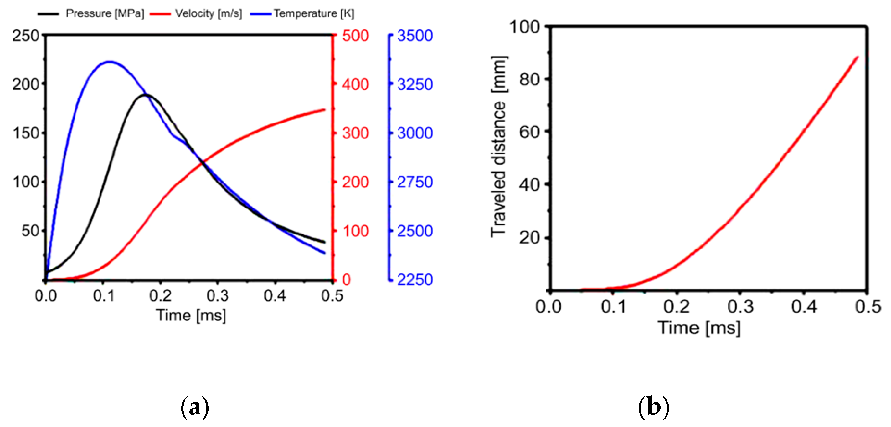
Figure 3.
Schematic of heat transfer in the barrel and barrel housing.

Figure 4.
Numerical simulation model for barrel cross-section.
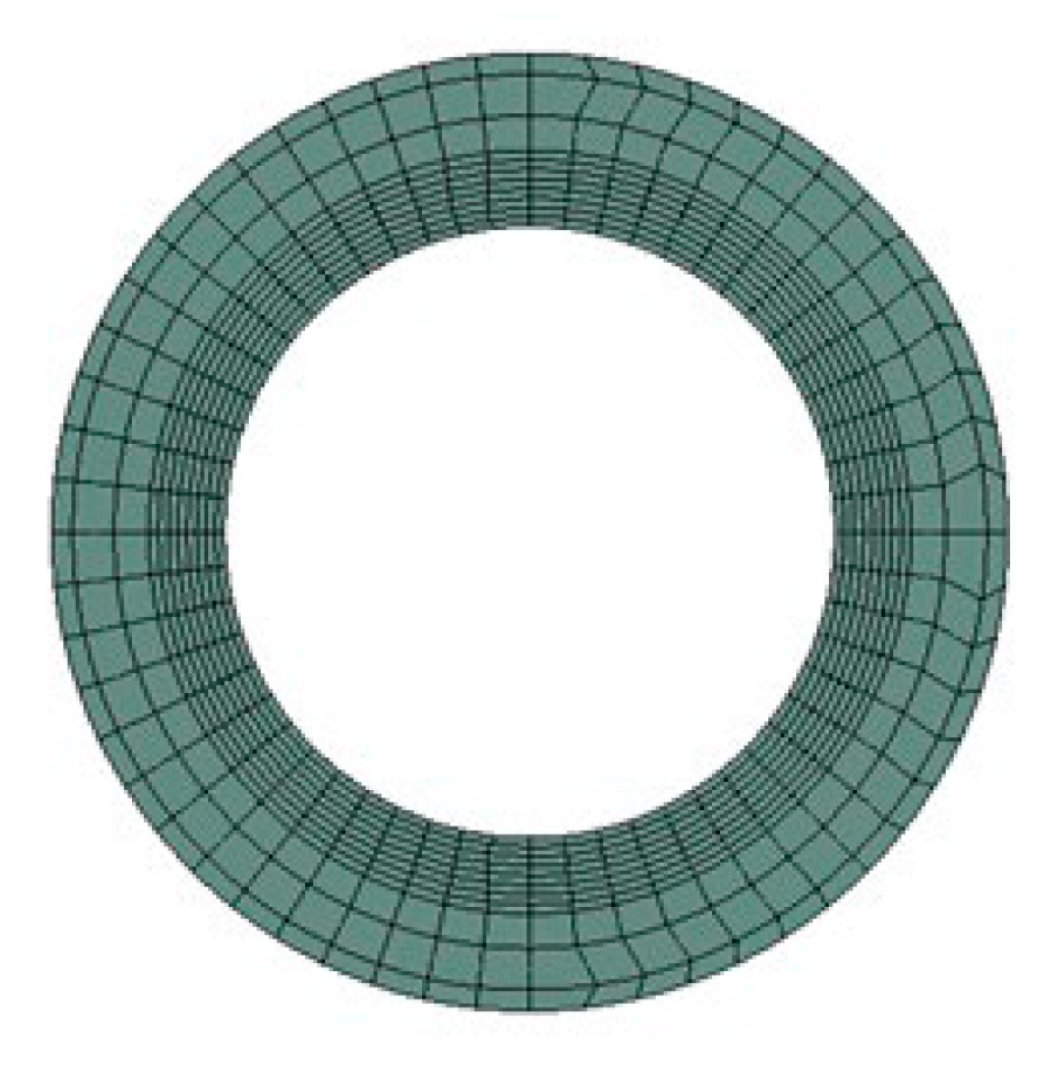
Figure 5.
Boundary conditions applied at the interior surface of the barrel—(a) dividing the cylinder and barrel into regions; (b) and applied to each region for 0.5 ms.
Figure 5.
Boundary conditions applied at the interior surface of the barrel—(a) dividing the cylinder and barrel into regions; (b) and applied to each region for 0.5 ms.
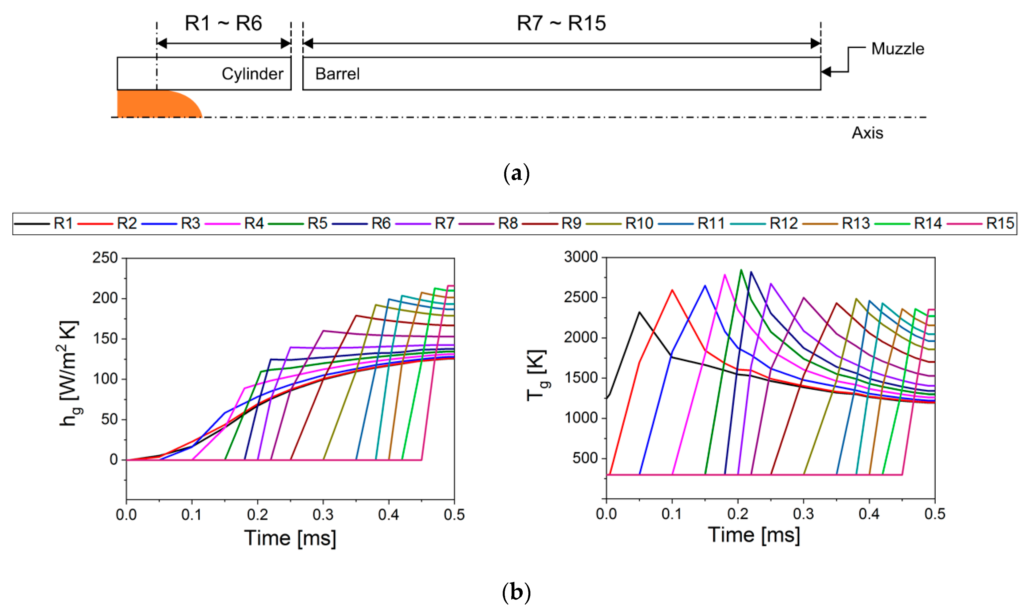
Figure 6.
Mesh model for gas-leak simulation.
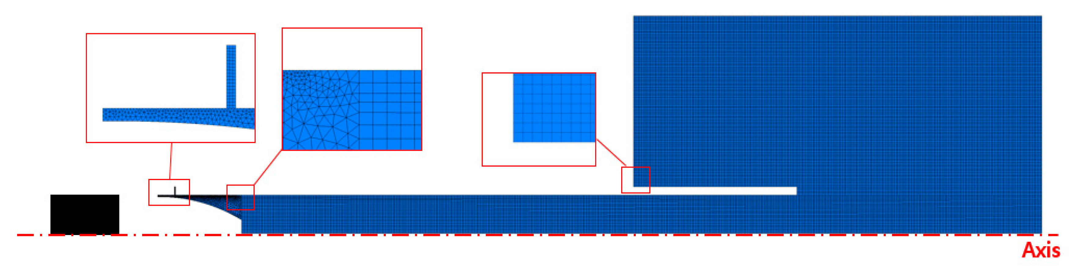
Figure 7.
Schematic of the initial and boundary conditions.
Figure 8.
Heat transfer and mechanical stress analysis results—(a) maximum temperatures of barrel and barrel housing over time and (b) maximum stress in the barrel over projectile travel distance.
Figure 8.
Heat transfer and mechanical stress analysis results—(a) maximum temperatures of barrel and barrel housing over time and (b) maximum stress in the barrel over projectile travel distance.
Figure 9.
Simulation results around the gap with respect to the cylinder gap—(a) pressure; (b) velocity; and (c) temperature.
Figure 9.
Simulation results around the gap with respect to the cylinder gap—(a) pressure; (b) velocity; and (c) temperature.
Figure 10.
Simulation results for various cylinder gap sizes—(a) mass-flow rate and (b) gas-leakage ratio
Figure 10.
Simulation results for various cylinder gap sizes—(a) mass-flow rate and (b) gas-leakage ratio

Table 1.
Parameters for obtaining the heat transfer coefficient.
| Kf | D | Pr | Ke | γ |
|---|---|---|---|---|
| 0.023 W/mK | 8.8 mm | 0.7 | 1.75 | 49 × 10−5 m2/s at 2.800 K |
Table 2.
Dynamic pressure applied inside the barrel.
| Distance Traveled by Projectile from Barrel Entrance [mm] | Time [ms] | Pressure [MPa] |
|---|---|---|
| 6 | 0.25 | 137 |
| 18 | 0.3 | 100 |
| 41 | 0.48 | 63 |
| 76 | 0.5 | 40 |
Table 3.
Properties for barrel and barrel housing.
| Parts | E [GPa] | ν | αT [/K] | ρ [kg/m3] | Specific Heat, c [J/kg·K] | k [W/m·K] |
|---|---|---|---|---|---|---|
| Barrel | 210 | 0.3 | 1.2 × 10⁻⁵ | 7850 | 434 | 60.5 |
| Barrel housing | 71 | 0.3 | 2.3 × 10⁻⁵ | 2770 | 875 | 170 |
Table 4.
Dynamic mesh zone setting.
| Type | Dynamic Mesh Zone | Six DOF Options |
|---|---|---|
| Rigid body | Projectile | On |
| Moving Fluid Region | On | |
| Stationary body | Breech, Outlet_a | - |
Table 5.
Molecular weight of the fluid region.
| Name | Mw [g/mol] | Description |
|---|---|---|
| Fluid_1 | 26.33 | Before combustion, propellant Mw |
| Fluid_2 | 33.38 | After combustion, Mw of the major components of the propellant |
| Fluid_3 | 39.5 | 1.5 times Mw of Fluid_1 |
Table 6.
Comparison of internal ballistics code data with computational fluid dynamics (CFD) simulation results.
Table 6.
Comparison of internal ballistics code data with computational fluid dynamics (CFD) simulation results.
| Name | Velocity at the Muzzle [m/s] | Travel Time [ms] |
|---|---|---|
| Ballistic Data | 347 | 0.31 |
| Fluid_1 | 335 | 0.318 |
| Fluid_2 | 341 | 0.316 |
| Fluid_3 | 345 | 0.314 |
Table 7.
Fluid properties of the propellant.
| ρ | Mw [g/mol] | cp [J/gK] | k [W/mK] | Molecular Viscosity [kg/m·s] |
|---|---|---|---|---|
| Equation (18) | 39.5 | 1870 | 0.0242 | 1.7894 × 10⁻⁵ |
Table 8.
Velocity of the projectile and the time at which it reached the muzzle for different cylinder- gap sizes.
Table 8.
Velocity of the projectile and the time at which it reached the muzzle for different cylinder- gap sizes.
| Cylinder Gap Size [mm] | Velocity [m/s] | Time [ms] |
|---|---|---|
| 0.1 | 348 | 0.312 |
| 0.15 | 345 | 0.314 |
| 0.3 | 337 | 0.318 |
© 2020 by the authors. Licensee MDPI, Basel, Switzerland. This article is an open access article distributed under the terms and conditions of the Creative Commons Attribution (CC BY) license (http://creativecommons.org/licenses/by/4.0/).
Share and Cite
MDPI and ACS Style
Yoon, J.; Park, J.; Park, J. Numerical Simulation and Design of a High-Temperature, High-Pressure Fluid Transport Pipe. Appl. Sci. 2020, 10, 5890. https://doi.org/10.3390/app10175890
AMA Style
Yoon J, Park J, Park J. Numerical Simulation and Design of a High-Temperature, High-Pressure Fluid Transport Pipe. Applied Sciences. 2020; 10(17):5890. https://doi.org/10.3390/app10175890
Chicago/Turabian StyleYoon, Jiyoung, Junkyu Park, and Jinhyoung Park. 2020. "Numerical Simulation and Design of a High-Temperature, High-Pressure Fluid Transport Pipe" Applied Sciences 10, no. 17: 5890. https://doi.org/10.3390/app10175890
Note that from the first issue of 2016, this journal uses article numbers instead of page numbers. See further details here.