Article

Performance Evaluation of Current Leads for a 5 Tesla Electromagnetic Properties Measurement System

Korea Basic Science Institute, Daejeon 34133, Korea
*
Author to whom correspondence should be addressed.
Appl. Sci. 2020, 10(19), 6712; https://doi.org/10.3390/app10196712
Submission received: 28 August 2020 / Revised: 24 September 2020 / Accepted: 24 September 2020 / Published: 25 September 2020
(This article belongs to the Special Issue Superconductor Technologies and Their Applications)

Abstract

:
The development of the Electromagnetic Property Measurement System is underway at the Korea Basic Science Institute. The Electromagnetic Property Measurement System is used for electrical, thermal, and magnetic specimen property measurements in variable magnetic fields and temperatures with a low-temperature superconducting magnet. To activate low-temperature superconducting magnet that operates with liquid helium, we propose the use of vapor-cooled current leads. The low-temperature superconducting magnet is connected to the power supply at room temperature through a pair of current leads. Accordingly, heat inflows through the current leads and represents one of the major contributory factors of the entire heat inflow. Therefore, design optimization and evaluation of the current leads is necessary to minimize heat and liquid helium consumption. Vapor-cooled, and hybrid current leads were designed and fabricated, and testing in liquid helium cryostat was conducted. The low-temperature superconducting magnet was charged with electrical current up to the operating level, and the liquid helium boil-off rate was measured with respect to the supplied electrical current level. The performances of the two current leads were accessed based on the thermal load and boil-off rate of the liquid helium. The experimental and analyzed liquid helium boil-off rates associated with the current leads were in close agreement.

1. Introduction

Increased magnetic fields required for power applications are generated by superconducting magnets. Superconducting magnets are usually activated by currents supplied from a power source at room temperature [1]. Energy level is varied depending on the size of the superconducting magnet and the current that passes through the current leads. The power source must be connected to the superconducting magnet by a pair of current leads with the operating temperatures in a range between room temperature and 4.2 K. Therefore, any heat leakages into the superconducting magnet system must be minimized or eliminated.
Typically, superconducting devices are mainly composed of three main components, namely, the superconducting magnet, current leads, and the cryogenic cooling system. The use of superconducting devices for energy application has attracted considerable attention because it generates relatively high-magnetic field strengths as compared with the conventional power device [2]. For example, superconducting cables were shown to (a) have 60–70% lower losses than conventional ones and (b) have the ability to prevent over-current flows [3]. The high temperature superconducting (HTS) power devices, such as HTS motor [4] and HTS fault current limiter [5], are beneficial not only in terms of energy but also in environmental and economic terms, reducing the use of oil and the size of equipment by more than half. Zhu et al. demonstrated the implementation and use of a high-temperature superconducting energy storage system for renewable power grids. They used yittrium barium copper oxide (YBCO) tapes to build the superconducting magnet with an operating current of 10 A at temperatures in the range of 65 to 77 K [6]. In the superconducting magnetic energy storage (SEMS) system, the length of current lead supplying the current to the superconducting magnet was designed based on consideration of the layout of the SMES components [7]. In such superconducting magnet application systems, the current lead connecting the superconducting magnet and the power supply is very important. HTS tapes can be attractive materials for current leads because they have high current density and low thermal conductivity. Several laboratories are presently investigating the development of a current lead using HTS tapes. Research groups such as the National Institute for Fusion Science [8,9,10], Yonsei University [11], and Huazhong University of Science and Technology have performed research related to HTS current leads [12]. The Karlsruhe Institute of Technology has recently manufactured the HTS current leads for the current supply of the satellite tokamak JT-60SA [13]. The aim of the development is the design and construction of a 20 kA HTS current lead using Rare-Earth Barium Copper Oxide (REBCO) material. After manufacturing of the HTS current lead, it was tested in the test facility CuLTKa. Some other researches about HTS current lead have been performed for the Italian National Institute for Nuclear Physics magnet test facility [14]. In these researches regarding the current lead using HTS materials, it is important to demonstrate the applicability of HTS current lead in the actual application scale.
A research program involving the current leads for the Electromagnetic Property Measurement System (EMPS) is underway at the Korea Basic Science Institute. The objective of the project is the development of an efficient low temperature superconducting (LTS) magnet system cooled by continuous liquid helium. In addition, the LTS magnet has a wide bore as compared with the conventional device [15], therefore several samples can be installed in the magnetic space and physical and magnetic properties can be measured at the same time. The drawing of a 5 T superconducting magnet system used for property measurement applications is shown in Figure 1. As mentioned above, the system mainly consists of the superconducting magnet, current leads, and cryogenic system. The cryogenic vessel is composed of a liquid helium vessel, liquid nitrogen vessel, and a vacuum vessel. A pair of current leads is installed in the system, and both current leads are used to supply electrical current to the magnet. The 5 T superconducting magnet is installed and operated in the liquid helium vessel. The detailed specifications of the magnet are listed in Table 1. As indicated, the central magnetic field and energy of the magnet are, respectively, equal to 5.01 T and 15.2 kJ for electrical current of 45 A.
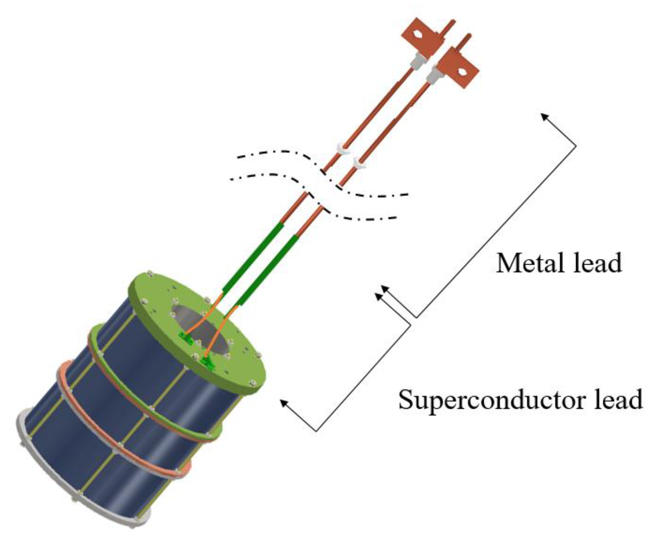
The vapor-cooled current lead was developed to supply current and generate an approximately magnetic field strength of 5 T in the EMPS. Design optimization was conducted to minimize helium consumption, and relevant tests were also performed. In addition, the hybrid type current lead was used because it eliminated conductive heat leakage. Figure 2 shows the detailed structure of the hybrid current lead. It is composed of (a) a metal lead made of copper or brass that conducts the current from room to an intermediate temperature, and (b) a high-temperature superconductor (HTS) lead that conducts the current at the liquid helium temperature. The metal lead is connected to the HTS lead at the joint and heat generation at the interface is affected by contact resistance [16].
As described above, two types of current lead for LTS magnet system have been proposed, in this study. The detailed design process such as material selection and size determination of vapor-cooled current lead has been investigated. After fabrication, the hybrid current lead was tested in the 5 T EMPS system and the results were compared to the results of design optimization. The effects of heat leakage through the current lead on the total cryogenic load in terms of liquid helium boil-off rate are also considered and discussed.

2. Design and Fabrication of the Current Leads

As shown in Figure 1, a pair of current leads were installed to supply electrical current to the superconducting magnet’s top plate at room temperature and the magnet itself at the liquid helium temperature. For a superconducting magnet that operates at 4.2 K, a vapor-cooled current lead can be a major source of heat leakage. Thus, design optimization is essential. The basic design concept for an optimum vapor-cooled lead is to remove the heat by funneling cold helium vapor through the lead.

2.1. Vapor-Cooled Current Lead

Vapor-cooled current leads are generally used in a superconducting magnet system that uses liquid helium, and they are cooled by the evaporated helium gas to minimize heat inflow [17]. Typically, copper and brass are used for the fabrication of current lead. The total heat input Qin flowing into and generated within a differential volume AΔz of vapor-cooled current leads carrying the current lead’s rated current I0 is expressed as Equation (1) [18]:
Q i n = [ A k ( T ) d T d z ] z + Δ z + m ˙ I C p ( T ) T + ρ ( T ) I 0   2 A Δ z
where z is the axial distance along the current lead, and z = 0 at the current lead’s cold end. The symbols k (T), A, and ρ (T), are the thermal conductivity, active cross-sectional area, and electrical resistivity of the current lead, respectively. The symbols m ˙ I and C p ( T ) denote the helium mass flow rate and specific heat, respectively. It is assumed that the heat transfer rate between liquid helium and current lead is perfect. The symbol T is the temperature of both at z. The total heat output Qout flowing out of the differential volume of AΔz is expressed as Equation (2) [18]:
Q o u t = [ A k ( T ) d T d z ] z + m ˙ I C p ( T ) ( T + Δ T )
In the steady state condition, The Qin and Qout are perfectly equal. Thus, Equation (3) [18] can be obtained as:
[ A k ( T ) d T d z ] z + Δ z [ A k ( T ) d T d z ] z m ˙ I C p ( T ) ( T + Δ T ) + ρ ( T ) I 0   2 A Δ z
dividing Equation (3) by Δz and replace Δz to 0, Equation (4) can be obtained as:
d d z [ A k ( T ) d T d z ] m ˙ I C p ( T ) d T d z + ρ ( T ) I 0   2 A
The heat input Q at the cold end for a given electrical current I, and the optimized shape ratio of vapor-cooled current leads are obtained from Equations (5) and (6), respectively [18] as follows:
Q I = h L k 0 ρ 0 c p 0
( I 0   L A ) = T 0 T l d T ρ ( T ) C p 0 k 0 ρ 0 h L
where hL, k0, ρ0, and Cp0 are latent heat of vaporization of liquid helium, thermal conductivity of metal current lead at cold end, electrical resistivity at cold end, and specific heat of liquid helium, respectively.
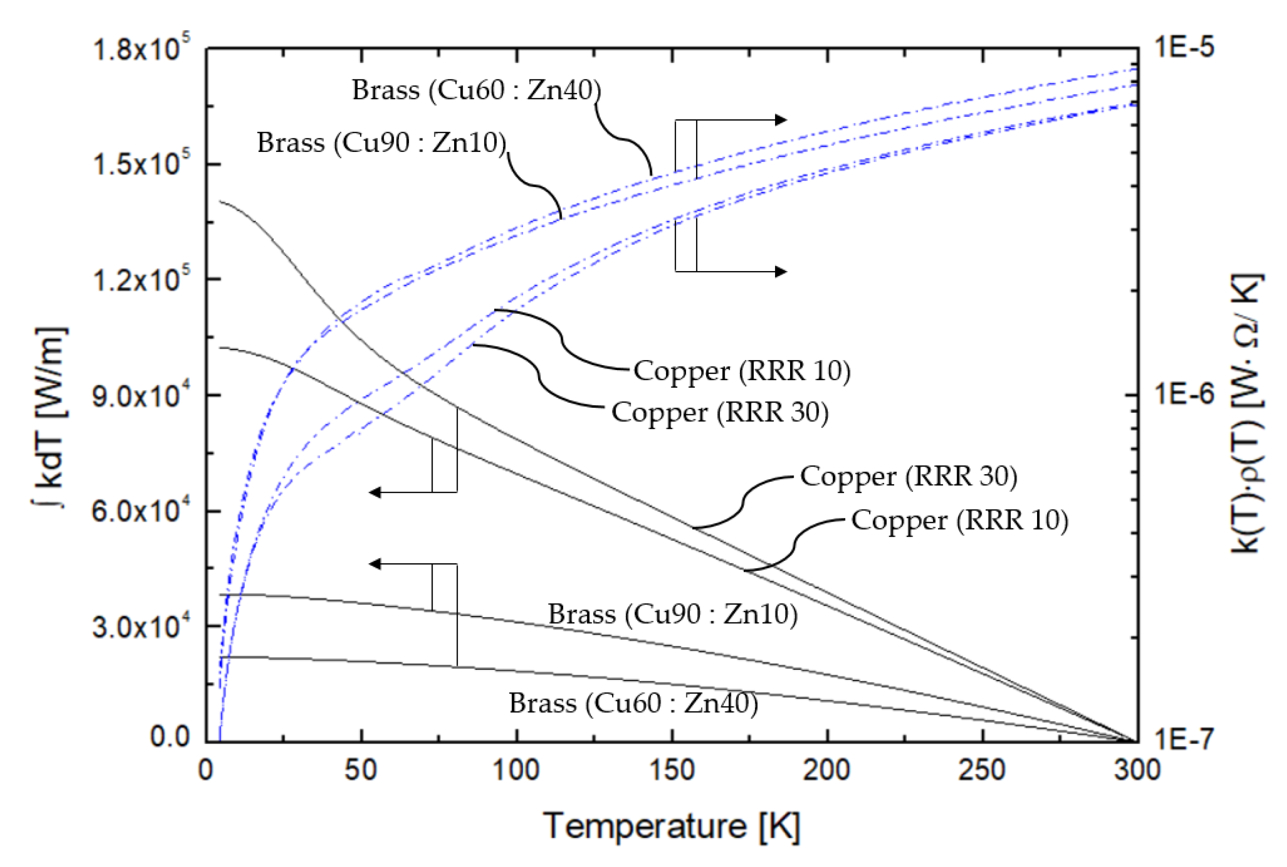
Figure 3 shows the thermal properties of the copper and brass. The solid line indicates the variations of the integral value of the thermal conductivity. The dashed line indicates the values obtained by multiplication of the thermal conductivity and electrical resistivity of brass and copper in the temperature range 4–300 K [19,20]. As indicated by Equation (2), the heat input value is related to the thermal properties.
The Q/I value, at the liquid helium temperature for brass (Cu90:Zn10) obtained through Equation (5), as well as for brass (Cu60:Zn40), copper RRR10, and copper RRR30 are 0.7332, 0.7560, 0.6153, and 0.6155 mW/A, respectively. The optimum shape ratio (I∙L/A) values calculated through Equation (6) for brass (Cu90: Zn10), brass (Cu60:Zn40), copper RRR10, and copper RRR30 are 1.967 × 10⁶, 1.036 × 10⁶, 9.008 × 10⁶, and 1.880 × 10⁷ A/m, respectively. For a more accurate design, the elemental analysis of commercially available brass was conducted with a glow discharge mass spectrometer (GDMS). Correspondingly, the ratio of copper to zinc was approximately 60:40 [21]. Considering the height of the cryostat for a 5 T superconducting magnet, the total length of the current lead is 0.98 m. For a length of 0.98 m, the cross-sectional areas of the brass (Cu60:Zn40) and copper RRR10 vapor-cooled current leads are 42.56 and 4.90 mm2, respectively. The shape ratio values indicate that the cross-sectional area of the brass current lead was approximately nine times that of copper.
Q 0 = h L   k   ˜ c p 0 ( A l ) ln [ c p 0 ( T l T 0 ) h L + 1 ]
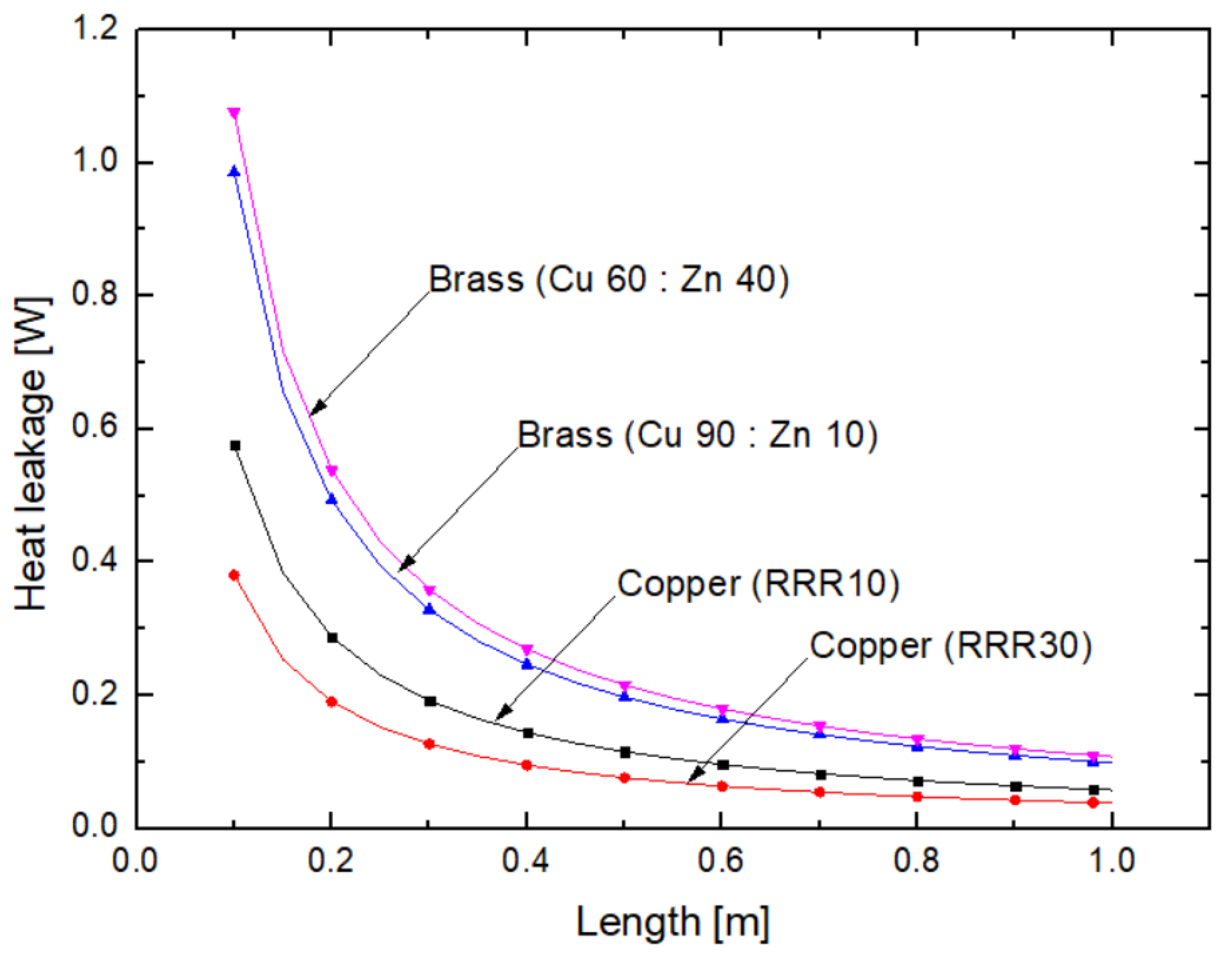
The minimum conductive heat input (Q0) at the cold end through the vapor-cooled current lead can be calculated through Equation (7) [18]. When copper RRR10, RRR 30, and brass (Cu 60: Zn 40) are used as the constituent materials of the vapor-cooled current lead, the conducted heat leakages per single current lead from room temperature to the temperature of liquid helium are 0.0294 W, 0.0190 W and 0.0549 W, respectively. When the current lead’s warm and cold ends are 300 K and 4 K, a conductive heat leakage with respect to the length of the current lead as a function of material is shown in Figure 4. The amount of conductive heat leakage decreases as the length of the current lead increases. When a 1 m length of copper (RRR10) is used as a metal current lead, conductive heat leakage is 0.057 W. When the length of the current lead is 0.98 m, the conductive heat leakage attributed to the two current leads is 0.0588 W for copper (RRR 10), 0.0380 W for copper (RRR 30), and 0.1098 W for brass (Cu 60:Zn 40).
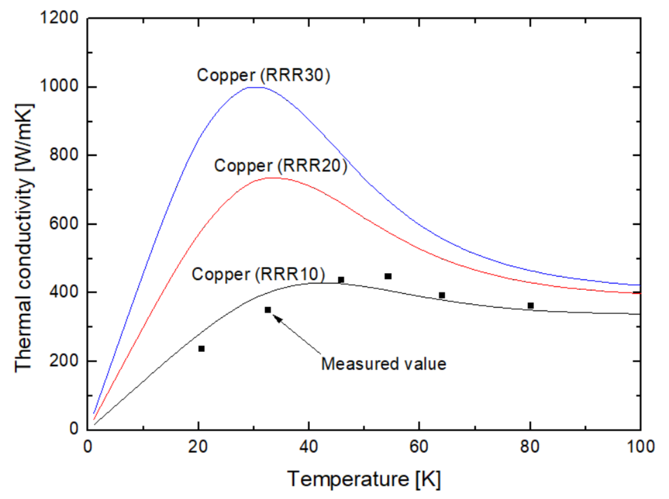
The heat generation of the current lead by electrical current should be considered. According to Ohm’s law, the resistance and heat generation of current lead are proportional to each other. Therefore, material with relatively low resistance should be selected. As a result of analyses with Equations (5)–(7), it is advantageous in terms of thermal and shape optimization to use copper as a material for vapor-cooled current leads rather than brass. Detailed calculation result values of current lead with respect to the material are summarized in Table 2. Accordingly, brass was not considered in the fabrication process of the current lead. We measured the thermal conductivity of the copper used in this system. In the previous study [22], the measurement system of thermal contact conductance and thermal conductivity was developed, and the thermal conductivity of copper test sample was obtained by measuring the temperature deviation that occurred when a specific amount of heat was applied to the test sample. The measured results are shown in Figure 5. As indicated, the measured values were in close agreement with the RRR 10 value. Therefore, the thermal properties of copper RRR 10 were used for the design of the current lead. There are various sources of heat leakage in the superconducting magnet system, including the instrumental wire conduction, support conduction, liquid helium vessel wall conduction, radiation, residual gas conduction, and heat leakage owing to current lead. Among these, heat leakage by current leads, conductive heat leakage by liquid helium vessel neck, and conductive heat leakage by residual gas account for approximately 90 % of the total heat leakage. When a 45 A electrical current is supplied through the current lead, the total amount of heat leakage of the superconducting magnet is 0.4322 W, and the liquid helium boil-off rate is predicted to be approximately 14.31 L/day. The heat leakage through current lead is 0.114 W accounting for 26% of the total heat leakage, which represents the largest proportion among each heat source. Therefore, the boil-off rate of liquid helium through the current lead must be minimized.

2.2. Hybrid Current Lead

The thermal heat leakage owing to the current leads can be divided into conductive heat transfer and Joule heating. To minimize the heat leakage attributed to the current lead, a hybrid with HTS tape whose critical temperature is approximately 90 K [23,24] can be a good option. Given that the resistance of the current lead is zero at the superconducting state [25], heat is not generated owing to electrical current.
Figure 6a,b shows the detailed structure of the hybrid current lead and the joint between the metal and HTS current lead, respectively. As indicated in Figure 6a, the hybrid current lead is composed of metal and HTS lead. The metal and HTS were jointed using soldering; and tube made of glass fiber reinforced plastic was installed around the HTS lead for protection. The HTS with 4 mm width and 200 A critical current at 77 K from SuNAM Co. (Anseong, Korea), Ltd. was used in this study [26]. The HTS tape was composed of several layers, including substrate, buffer, protection, and superconductor layers [27]. Among various layers of the HTS tape, some conductor layers such as the stainless steel layer used as a substrate, the copper layer used as a stabilizer layer, and the silver layer used as a protecting layer, can transfer conductive heat. However, the cross-sectional areas of these layers are very small, and the conductive heat transfer is also very small as compared with the metal current lead. The stacking structure of the HTS tape is an inevitable design feature to prepare for critical current degradation by physical damage of the HTS tape and to pass by the current when damaged. Therefore, three-layer stacked HTS tape was applied to the hybrid current lead in this study.
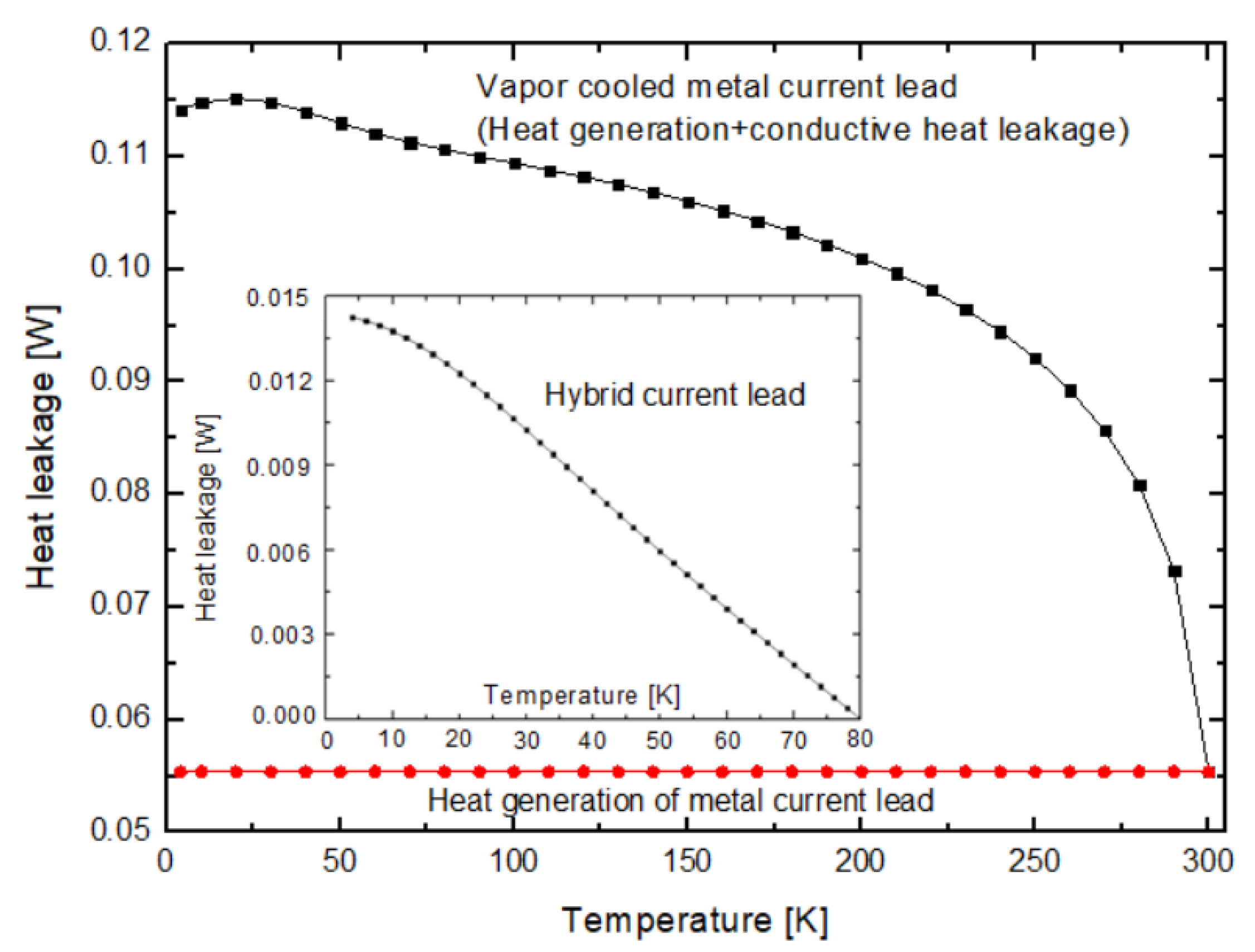
The heat leakages from the vapor-cooled and hybrid current leads are compared in Figure 7. As mentioned above, the heat leakage including the conductive heat using Equation (4) and the generated heat using Equation (2) is 0.114 W. In the case of hybrid current lead, conductive heat transfer occurs from approximately 80 K to the liquid helium temperature through intermediate cooling. Accordingly, heat is not generated because the resistance of the HTS tape is zero at temperatures below 80 K. The conductive heat transfer through the HTS tape calculated using the Fourier’s law conduction equation is 0.0143 W. When an electrical current of 45 A is supplied through the hybrid current lead, the total amount of heat leakage of the superconducting magnet is 0.3396 W, and the liquid helium boil-off rate is predicted to be approximately 11.23 L/day.

3. Experimental Setup

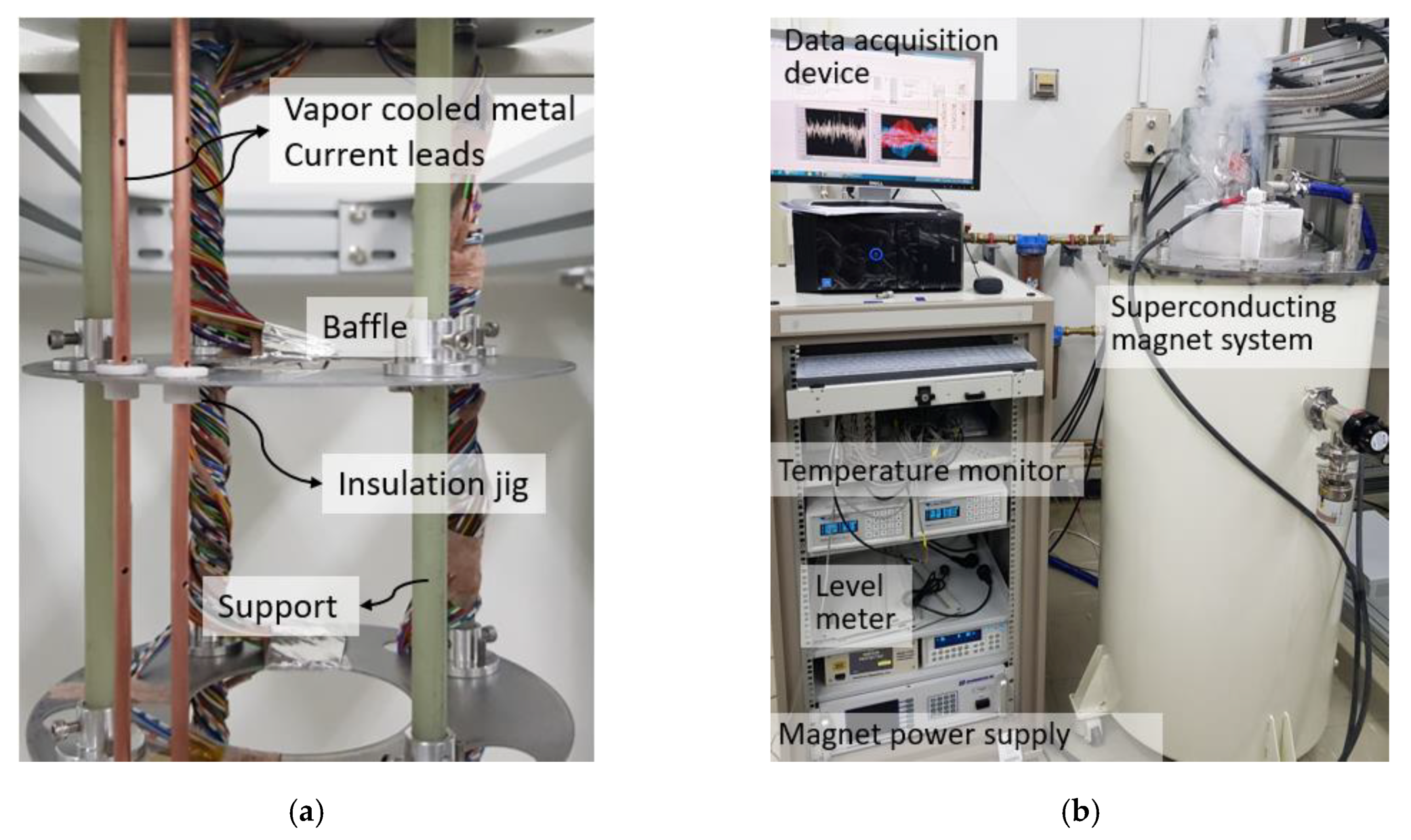
As shown in Figure 1, the cryostat for superconducting magnet is composed of a liquid helium vessel, liquid nitrogen vessel, and vacuum vessel. In general, the liquid nitrogen vessel surrounds the liquid helium vessel and the space between the liquid nitrogen vessel and liquid helium vessel is maintained in a vacuum condition to minimize conduction heat transfer by residual gas. The liquid nitrogen vessel has a capacity of about 70 L, and thirty layers of multilayer insulation (MLI) [28] is applied to minimize the radiant heat transfer and to maintain a temperature of 77 K. The liquid helium vessel has a capacity of about 76 L. A superconducting magnet, current leads, baffles, and liquid helium level sensor were installed inside the liquid helium vessel. In this experiment, we used the standard liquid helium level sensor from AMI [29], and it has an active length of 20 inches. Figure 8a shows the installation of the vapor-cooled current lead. Several baffles were installed in the superconducting magnet system for the minimization of the radiant heat leakage and the current lead was installed through the baffles. To prevent electrical contact between the baffles and the current lead, an insulation jig made of Teflon was installed, as shown in Figure 8a. There were four supports for installing the superconducting magnet in the system, which were made of glass fiber reinforced plastic with lower thermal conductivity than metal material, because they were directly connected to a superconducting magnet from room temperature like current leads. Figure 8b shows the experimental setup of a 5 T superconducting magnet system for the performance test of the current lead with data acquisition device. The data acquisition device consists of a computer for collection of experimental data, temperature monitor (model Lakeshore 218, Lakeshore Cryotronics Inc., Westerville, OH, USA) for temperature measurement, gauss meter (model Lakeshore 475, Lakeshore Cryotronics Inc., Westerville, OH, USA) for magnetic field energy measurements, and level meter (model AMI 1700, American Magnetics Inc., Oak Ridge, TN, USA) for liquid helium level measurements. The electrical current was supplied via a magnet power supply (model Cryomagnetics 4G-200, Cryomagnetics Inc., Oak Ridge, TN, USA) equipped with a quench protection module and a free ramping rate control. All instruments were controlled with the LabviewTM software (Labview 2017, National Instruments, Austin, TX, USA), and the experimental data were saved automatically every second through the GPIB communication module.

4. Results and Discussions

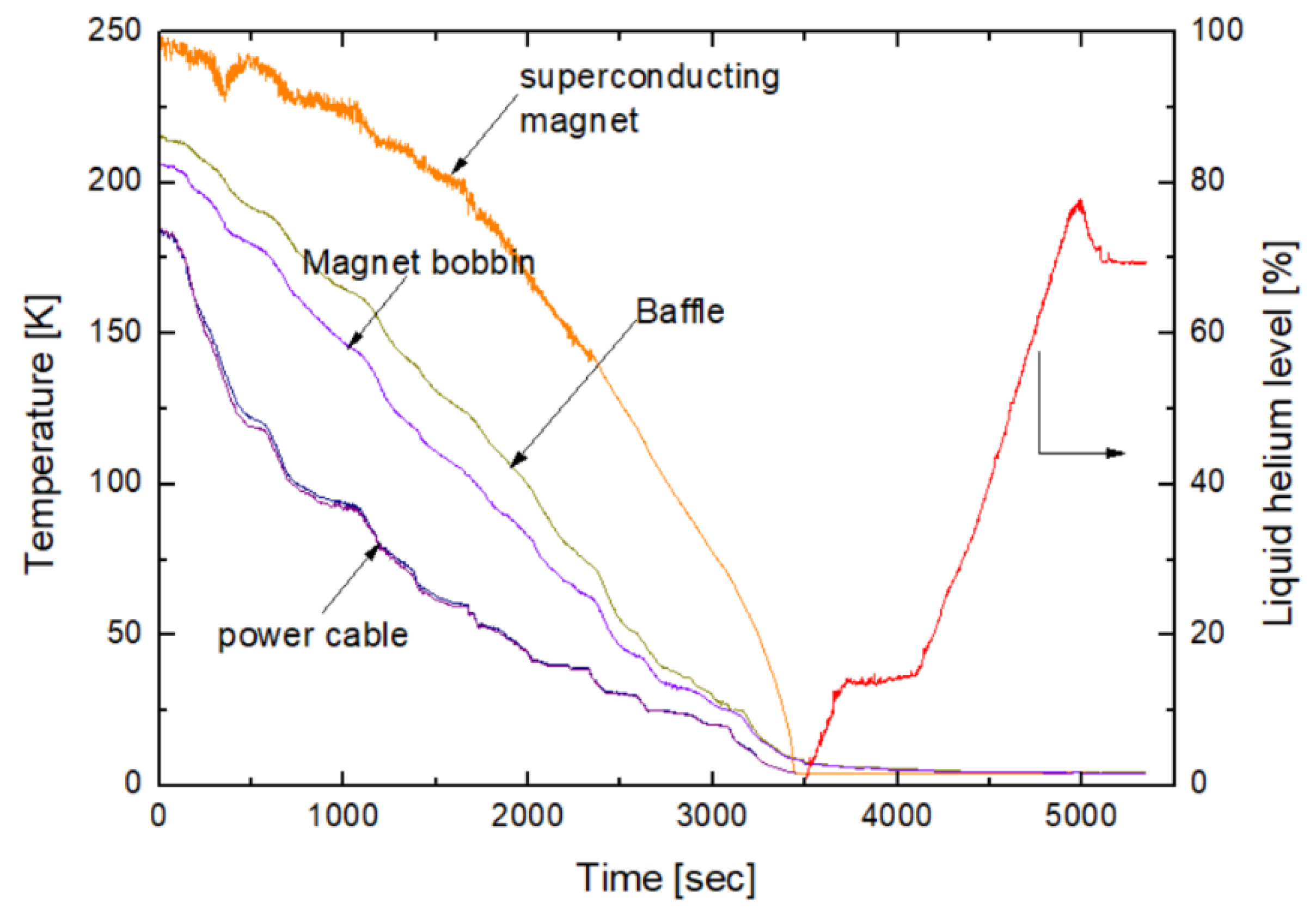
Figure 9 shows the cool-down curve of the superconducting magnet system, while liquid helium is supplied to the cryostat. In order to reduce the heat leakage by residual gas conduction and minimize the affection to the boil-off test results, a vacuum environment was maintained of about 0.018 Pa during the whole experimental process. To minimize the use of liquid helium, initial cooling was performed first by filling the liquid nitrogen container before liquid helium was supplied. The temperature of the superconducting magnet was measured using platinum resistance thermometer (accuracy rating ± 0.5 K) and it was approximately 250 K. The temperature sensor (model Lakeshore CernoxTM 1010-AA, Lakeshore Cryotronics Inc., Westerville, OH, USA) on the current lead and baffle was installed at a position of about 590 mm from the top part of the system, and operated at approximately 180 and 215 K. It took approximately 1.2 h for the temperature of the superconducting magnet to cool to the liquid helium temperature. The amount of liquid helium was measured with a helium level sensor (model AMI liquid helium level sensor, American Magnetics Inc., Oak Ridge, TN, USA). After liquid helium was supplied, the level of liquid helium was approximately 69.72%. The quantity of liquid helium per 1% level was 0.69 L and the total amount of liquid helium was approximately 48.11 L.
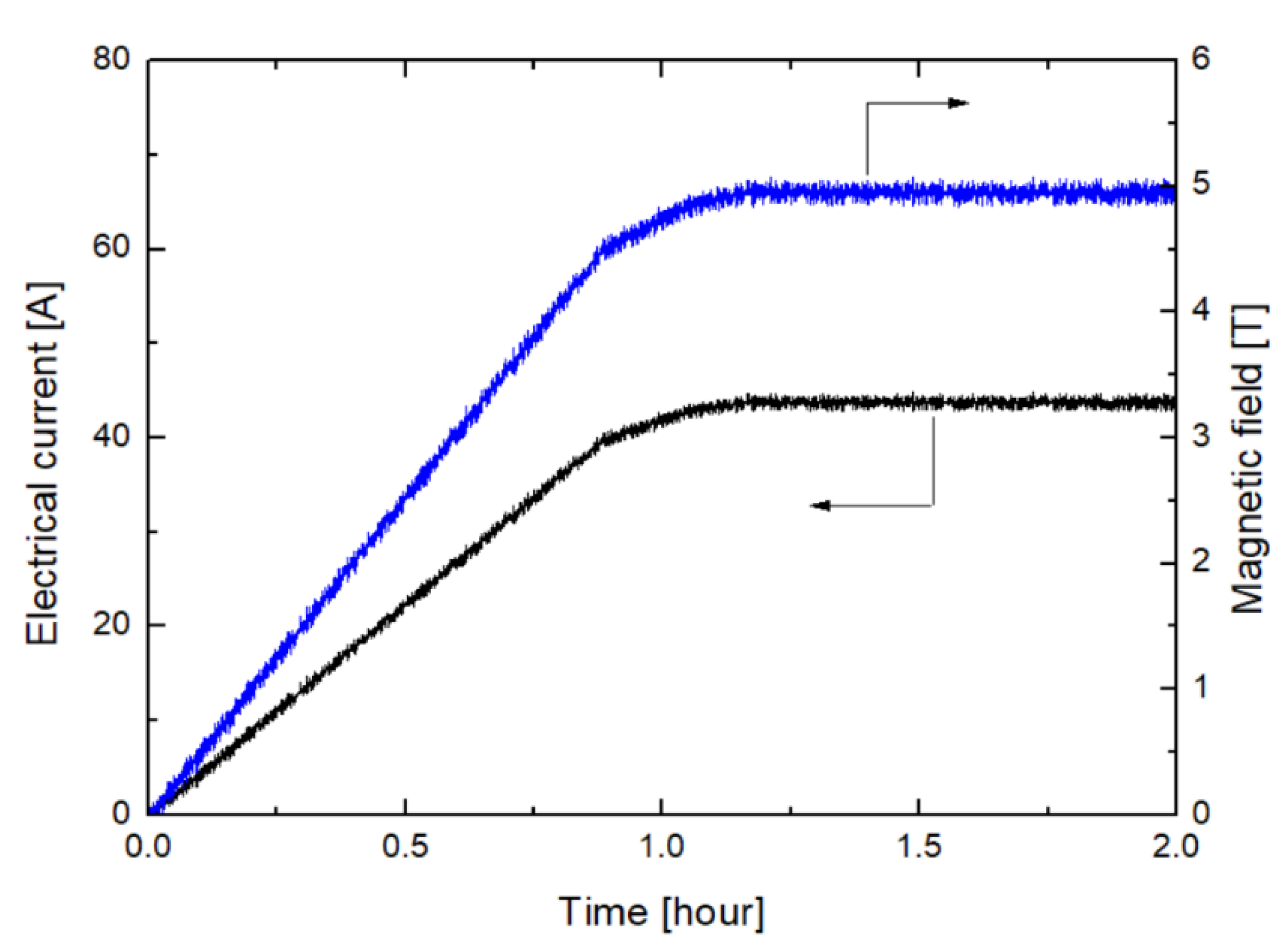
Figure 10 shows the magnetic field variation with respect to the supplied electrical current. After the liquid helium was transferred, the electrical current was supplied to the superconducting magnet to generate magnetic field. The ramping rate of electrical current was 0.75 A/min and the operating range was 0–40 A. For currents in the range from 40 to 45 A, the ramping rate of electrical current was 0.3 A/min. It took approximately 1.1 h to reach the magnetic field of 5 T, and this magnetic field was maintained subsequently during 0.8 h. After reaching the magnetic field of 5 T, when the liquid helium level was approximately 30%, the temperature of the warm end (joint with vapor-cooled metal lead) and the cold end (joint with LTS magnet) of the HTS current lead was maintained approximately at 10 and 4.2 K, respectively.
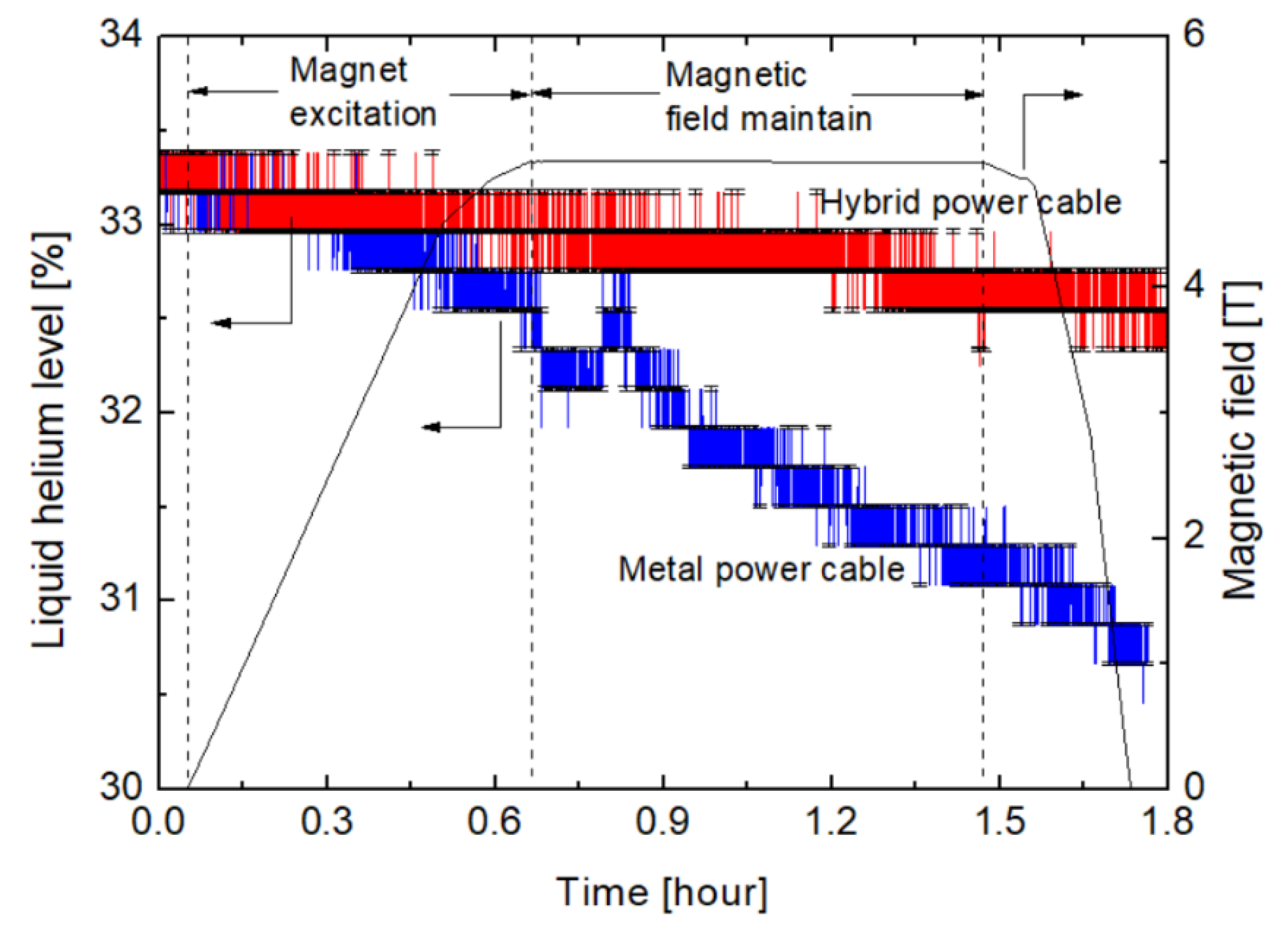
Figure 11 shows the liquid helium level variations with respect to the magnetic field for different current leads. The cooling and magnetic field generation experiments of superconducting magnet system were conducted to assess the performances of the two types of current lead. After the superconducting magnet was cooled to 4.2 K, 45 A electrical current was supplied to generate 5 T magnetic field. Furthermore, the performance of the current lead was evaluated based on the calculation of the amount of liquid helium that decreased, while the magnetic field was maintained constant. As shown in Figure 11, when measuring the liquid helium level, a fluctuation of about ±0.6% occurred by signal noise. The experimental results obtained during the boil off of liquid helium used the average value for 30 s.
When the vapor-cooled current lead was applied, the liquid helium level decreased from 32.34% to 31.60%, while the magnetic field of the superconducting magnet was maintained at 5 T. The liquid helium level was decreased by 0.74% over the 0.8 h time span, as shown in Figure 11. The decreasing rate of liquid helium was approximately 15.21 L/day. As mentioned earlier in the design section of the vapor-cooled current lead, the calculated liquid helium boil-off rate was approximately 14.31 L/day. The results of the experiment boil-off test agreed with the analysis and were within a 6.0% margin.
In the case of the hybrid current lead, the liquid helium level decreased by 0.56% during the 0.8 h time from 32.97% to 32.41%. The decreasing rate of liquid helium was approximately 11.53 L/day. The difference between the test and the design results of the hybrid current lead was within 2.6%. When the hybrid current lead was applied, the boil-off rate of liquid helium decreased by approximately 24% from 15.21 to 11.53 L/day as compared with those of the vapor-cooled current lead. The results of a longer test of more than 1 h, indicated that the slope of the liquid helium level decreases as time passes because the amount of conduction heat leakage through the neck of liquid helium vessel decreases. The boil-off test of each current lead was performed several times at different liquid helium level and the repeatability of result was within 2%. The representative test result values are indicated in Table 3.

5. Conclusions

We successfully designed, fabricated, and tested current leads used for the generation of magnetic field in superconducting magnet systems. The vapor-cooled and hybrid current leads were developed, and both current leads successfully generated a magnetic field of 5 T at the operating current of 45 A. Both leads were installed in 5 T superconducting magnet systems, and performance tests were conducted based on measurements of the boil-off rate of liquid helium when electrical current was supplied to the magnet. The boil-off rate of liquid helium decreased by approximately 24% when the hybrid current lead was applied as compared with the vapor-cooled current lead. It was confirmed that the minimization of the generated heat by the hybrid current lead achieves efficient reduction of the liquid helium boil-off rate. As the consumption of liquid helium decreases, the 5 T magnetic field of the superconducting magnet can be maintained for a longer time. The time to maintain the 5 T magnetic field increased, therefore, the constraints of properties measurement were diminished, and the hall coefficient measurement was possible at various angles and temperatures. The Electromagnetic Property Measurement System with a central magnetic field of 9 T and a wide room temperature bore above 2 inches or more will be developed under Korea Basic Science Institute. The design and manufacturing technique, and test results of the current lead obtained through this study will be applied to a 9 T Electromagnetic Property Measurement System.

Author Contributions

Design, J.Y.J. and Y.J.H.; test and data acquisition, M.S.K.; writing—original draft preparation, M.S.K.; writing—review and editing, Y.S.C. All authors have read and agreed to the published version of the manuscript.

Funding

This research was funded by the Korea Basic Science Institute (KBSI) grant number D010200.

Conflicts of Interest

The authors declare no conflict of interest.

Nomenclature

QinTotal heat input
ACross-sectional area
zAxial distance along the current lead
I0Thermal conductivity
k(T)Brood termination rate
ρ(T)Electrical resistivity
m ˙ I Helium mass flow rate
Cp(T)Specific heat of liquid helium
hLLatent heat of liquid helium
k0Thermal conductivity of metal current lead at cold end
ρ0Electrical resistivity at cold end

References

  1. Wilson, M.N. Current Supply. In Superconducting Magnets, 1st ed.; Oxford Science Publications: New York, NY, USA, 1986; pp. 256–278. [Google Scholar]
  2. Lee, S.J.; Yang, H.S. Recent progress and design of three-phase coaxial HTS power cable in Korea. IEEE Trans. Appl. Supercond. 2019, 29, 5402705. [Google Scholar] [CrossRef]
  3. Hartikainen, T.; Mikkonen, R.; Lehtone, J. Environmental advantages of superconducting devices in distributed electricity-generation. Appl. Energy 2007, 84, 29–38. [Google Scholar] [CrossRef]
  4. Moon, H.J.; Kim, Y.C.; Park, H.J.; Park, M.W.; Yu, I.K. Development of a MW-Class 2G HTS ship propulsion motor. IEEE Trans. Appl. Supercond. 2016, 26, 5203805. [Google Scholar] [CrossRef]
  5. Lee, H.S.; Kang, H.K. Conceptual design of a resistive 154-kV/2-kA superconducting fault current limiter. IEEE Trans. Appl. Supercond. 2016, 26, 5601805. [Google Scholar] [CrossRef]
  6. Zhu, J.; Yuan, W.; Qiu, M.; Wei, B.; Zhang, H.; Chen, P.; Yang, Y.; Zhang, M.; Huang, X.; Li, Z. Experimental demonstration and application planning of high temperature superconducting energy storage system for renewable power girds. Appl. Energy 2015, 137, 692–698. [Google Scholar] [CrossRef] [Green Version]
  7. Shi, J.; Xu, Y.; Liao, M.; Guo, S.; Li, Y.; Ren, L.; Su, R.; Li, S.; Zhou, X.; Tang, Y. Integrated design method for superconducting magnetic energy storage considering the high frequency pulse width modulation pulse voltage on magnet. Appl. Energy 2019, 248, 1–17. [Google Scholar] [CrossRef]
  8. Zhang, S.; Feng, H.; Zhuang, M.; Ding, K.; Liu, C.; Zhou, Y. Experimental Research of a 10 kA HTS Current Lead Using YBCO Tapes. IEEE Trans. Appl. Supercond. 2020, 30, 4801307. [Google Scholar] [CrossRef]
  9. Yamada, Y.; Ishii, Y.; Sakai, S.; Shiohara, K.; Tachikawa, K.; Aoki, Y.; Kaneko, A.; Koizumi, T.; Tamura, H.; Mito, T. HTS current leads prepared by the TFA-MOD processed YBCO tapes. IEEE Trans. Appl. Supercond. 2011, 21, 1054–1057. [Google Scholar] [CrossRef]
  10. Matsumura, R.; Hosono, Y.; Tanimoto, R.; Yamada, Y.; Takahashi, K.; Hironaga, R.; Hasegawa, T.; Tamura, H.; Mito, T. Transport Performance and Current Distribution of HTS Current Lead Prepared by YBCO Tapes. IEEE Trans. Appl. Supercond. 2015, 26, 4800104. [Google Scholar] [CrossRef]
  11. Lee, W.S.; Hwang, Y.J.; Kim, J.; Nam, S.; Park, Y.G.; Ko, T.K. Quench Protection for HTS Current Leads by Adding Connected HTS Bridges. IEEE Trans. Appl. Supercond. 2014, 24, 4801804. [Google Scholar]
  12. Ren, L.; Tang, Y.; Li, J.; Li, Z.; Chen, L.; Chen, J.; Shi, J.; Wen, J. Conduction-cooled YBCO HTS current lead for SMES application. IEEE Trans. Appl. Supercond. 2010, 20, 1737–1740. [Google Scholar] [CrossRef]
  13. Fietz, W.H.; Heller, R.; Kienzler, A.; Lietzow, R. High Temperature Superconductor Current Leads for WENDELSTEIN 7-X and JT 60SA. IEEE Trans. Appl. Supercond. 2009, 19, 2202–2205. [Google Scholar] [CrossRef]
  14. Saggese, A.; Iannone, G.; Gambardella, U.; Califano, N.; Ferrentino, A. 20 kA HTS Current Leads for the INFN Magnet Test Facility. IEEE Trans. Appl. Supercond. 2014, 25, 4801304. [Google Scholar] [CrossRef]
  15. Oshi, I.; Naoaki, K.; Misato, T.; Yusuke, Y.; Satoshi, A.; Koichi, M. Thermal expansion and magnetostriction measurement using Quantum Design Physical Property Measurement System. J. Phys. Conf. Ser. 2014, 568, 032002. [Google Scholar]
  16. Kim, M.S.; Choi, Y.S. Interfacial contact resistance along the thermal link in conduction-cooled low temperature superconducting magnet system. J. Supercond. Nov. Magn. 2015, 28, 681–684. [Google Scholar] [CrossRef]
  17. Lee, H.G.; Paul, A.; Kenneth, R.E.; Yukikazu, I. Helium vapor-cooled brass current lead: Experimental and analytical results. Cryogenics 2001, 41, 485–489. [Google Scholar] [CrossRef]
  18. Yukikazu, I. Case Studies in Superconducting Magnets; Plenum Press: New York, NY, USA, 1994; pp. 125–162. [Google Scholar]
  19. Cryogenic Technology Resources. Available online: https://trc.nist.gov/cryogenics/aboutCryogenics (accessed on 15 April 2020).
  20. Ekin, J. Experimental Techniques for Low-Temperature Measurements; Oxford University Press: New York, NY, USA, 2006; pp. 517–536. [Google Scholar]
  21. Kim, M.S.; Choi, Y.S. Characteristics of conduction-cooled binary current leads used in cryogen free probe station. IEEE Trans. Appl. Supercond. 2017, 27, 4800404. [Google Scholar]
  22. Kim, M.S.; Seo, Y.H.; Choi, Y.S. Thermal contact conductance of various metal interfaces at cryogenic temperature. Int. J. Nanotechnol. 2019, 16, 213–219. [Google Scholar] [CrossRef]
  23. Miao, W.; Wan-min, Y.; Jia-wei, L.; Zhong-Ling, F.; Peng-Tao, Y. F Comparison of the superconducting properties in GdBCO bulk superconductors fabricated with two different solid phases. Supercond. Sci. Technol. 2015, 28, 035004. [Google Scholar]
  24. Park, S.; Cho, B.; Park, H.; Ri, H.-C. Analysis of the local current in GdBCO coated conductors using low-temperature scanning laser and hall probe microscopy. Cryogenics 2012, 52, 744–748. [Google Scholar] [CrossRef]
  25. Lee, S.; Sung, H.; Park, M.; Won, D.; Yoo, J.; Yang, H.S. Analysis of the temperature characteristics of three-phase coaxial superconducting power cable according to a liquid nitrogen circulation method for real-grid application in Korea. Energies 2019, 12, 1740. [Google Scholar] [CrossRef] [Green Version]
  26. SuNAM Co., Ltd. Homepage. Available online: https://www.i-sunam.com (accessed on 20 June 2020).
  27. Ibi, A.; Fukushima, H.; Yamada, Y.; Miyata, S.; Kuriki, R.; Takahashi, K.; Shiohara, Y. Development of long GdBCO coated conductor using the IBAD/MPMT-PLD method. Supercond. Sci. Technol. 2006, 19, 1229–1232. [Google Scholar] [CrossRef]
  28. Fesmire, J.E.; Johnson, W.L. Cylindrical cryogenic calorimeter testing of six types of multilayer insulation systems. Cryogenics 2018, 89, 58–75. [Google Scholar] [CrossRef]
  29. American Magnetics Inc. Homepage. Available online: https://www.americanmagnetics.com (accessed on 11 September 2020).
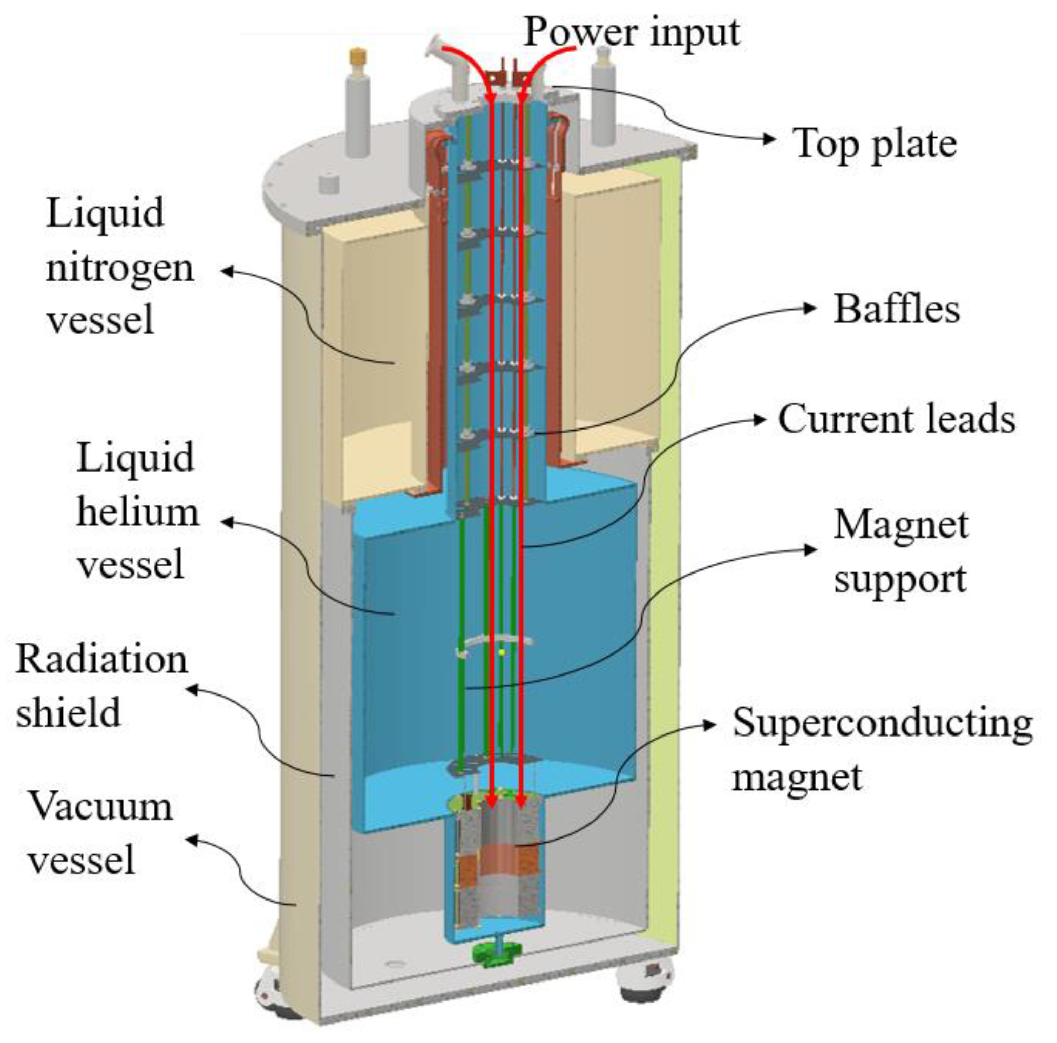
Figure 1. Drawing of the 5 T superconducting magnet for the Electromagnetic Property Measurement System (EMPS).
Applsci 10 06712 g001
Figure 2. Structure of hybrid current leads.
Applsci 10 06712 g002
Figure 3. Thermal properties of metals as a function of temperature.
Applsci 10 06712 g003
Figure 4. Heat leakage through the current lead composed of different materials as a function of its length.
Applsci 10 06712 g004
Figure 5. Thermal conductivity of copper with respect to temperature at different copper purity values.
Applsci 10 06712 g005
Figure 6. Structure of hybrid current lead. (a) Shape of the hybrid current lead; (b) Joint between metal current lead and HTS.
Applsci 10 06712 g006
Figure 7. Heat leakages of vapor-cooled and hybrid current leads.
Applsci 10 06712 g007
Figure 8. Experimental setup of the 5 T superconducting magnet system. (a) Installation of the vapor-cooled current leads; (b) Entire experimental setup including the data acquisition system.
Applsci 10 06712 g008
Figure 9. Cool-down curve for the 5 tesla superconducting magnet system.
Applsci 10 06712 g009
Figure 10. Magnetic field variation with respect to the supplied electrical current.
Applsci 10 06712 g010
Figure 11. Liquid helium level variation with respect to the magnetic field as a function of current lead.
Applsci 10 06712 g011
Table 1. Specifications of the low temperature superconducting magnet.
ParameterValueUnit
ConductorNbTi
Conductor length6.06km
Central magnetic field5.01tesla (T)
Operating current45A
Inductance15H
Magnetic field energy15.2kJ
Table 2. Summary of experimental results and as compare with the design value.
MaterialA (mm2) (L = 0.98 m)Conductive Heat LeakageHeat GenerationTotal Heat Leakage (W)
Brass (Cu 90: Zn 10)22.520.10050.065980.1665
Brass (Cu 60: Zn 40)42.560.10980.068040.1778
Copper (RRR30)2.380.03800.05540.0934
Copper (RRR10)4.900.05880.05520.1140
Table 3. Summary of experimental results as compare with the design value.
Vapor-Cooled Metal Current Lead (Copper RRR10)Hybrid Current Lead
Design valueTest valueDesign valueTest value
Heat leakage0.4322 W0.4599 W0.3396 W0.3486 W
Boil-off rate14.31 L/day15.21 L/day11.23 L/day11.53 L/day
Decreasing rate21.53%24.19%