Article

Numerical and Experimental Studies of the ŁK Type Shaped Charge

1
Department of Mechanics, Materials and Biomedical Engineering, Wroclaw University of Science and Technology, Smoluchowskiego 25 str., 50-370 Wroclaw, Poland
2
Department of Lightweight Elements Engineering, Foundry and Automation, Wroclaw University of Science and Technology, Lukasiewicza 7-9 str., 50-371 Wroclaw, Poland
3
Institute of Mechanics and Printing, Faculty of Production Engineering, Warsaw University of Technology, Narbutta 85 str., 02-524 Warsaw, Poland
4
Military Institute of Engineer Technology, Ammunition Testing Laboratory, Obornicka 136 str., 50-961 Wroclaw, Poland
*
Author to whom correspondence should be addressed.
Appl. Sci. 2020, 10(19), 6742; https://doi.org/10.3390/app10196742
Submission received: 15 August 2020 / Revised: 22 September 2020 / Accepted: 24 September 2020 / Published: 26 September 2020
(This article belongs to the Section Mechanical Engineering)

Abstract

:
In this paper, the authors presented an analysis of the strengthening of the cumulative jet by the appropriate formation of the detonation wave front acting under the influence of high pressure on the liner. The analysis of the Polish ŁK cumulative charge was carried out using numerical methods in the ABAQUS program. Simulation studies were carried out on axial and peripheral initiations of the explosive cumulative liner. For this purpose, two types of cumulative charges were made with the same design parameters, differing only in the explosive detonation-initiation system. The impact of the elastomer insert on the focusing of the cumulative jet was verified. The influence of peripheral and axial initiation on a cumulative jet’s velocity was investigated. The authors proposed a new conical insert placed in the explosive between the pocket for the detonator and the liner, also changing the material of the cumulative liner. The smoothed-particle hydrodynamics method was used to describe the formation of a cumulative jet. The obtained results were verified experimentally, and they show that modification of the ŁK charge has a positive effect on jet amplification, with an inevitable collapse in the final stage of formation. The obtained results correlate with the literature’s data.

1. Introduction

The described cumulative effect was already being used for military applications during World War II in many varieties of anti-tank weapons. Technological developments after World War II took a rapid leap in terms of the advancement of cumulative missiles.
The literature contains many studies of theoretical–experimental approaches to the problem [1,2,3,4], whereby many parameters related to the cumulative effect have been analyzed. This phenomenon is very well described from the physical point of view [5,6]. It should be noted that if a cone-shaped crater is hollowed out in a cylindrical explosive charge, its detonation will manifest a focusing of the explosive detonation products, generating intense local forces. This concentration of forces was used in the construction of shaped charges [6,7]. The lining of this cavity with a specific material called a liner creates a jet which is driven by the wave emitted by the detonation of the explosive [8]. The jet formation process is caused by an increase in the pressure of detonation products acting on the liner [9,10]. The liner collapses under this pressure. The decomposition of the resultant pressure wave into orthogonal components, i.e. the radial component and the axial component, causes, on the one hand, causes the liner material to be compressed, while on the other hand driving the compressed material along the axis of symmetry of the operation of the very high pressure. The result of the collapse of the liner is the classic Birkhoff effect [11,12], which results from the liner material in the slug and the jet (see Figure 1). As a consequence, this process leads to the creation of an appropriate and effective jet.
This effect can be strengthened by the appropriate formation of the detonation wave front [12,13].
This efficiency depends, among other things, on the type of insert material [6], its cone angle [14] and the speed of detonation wave front propagation (the so-called detonation velocity), “i.e., it depends on the explosive material used [15,16]”, and it usually amounts to 7–10 km/s.
Studies have also been carried out with tandem heads, investigating their efficiency for armor [17,18]. Among others, studies [19,20,21,22] have analyzed various materials and thicknesses of cumulative inserts. The asymmetry of constructional parameters was examined in study [20], while the influences of the casing material, the linear angle, the spacing and many other parameters affecting the efficiency of the cumulative charge were comprehensively included in studies [23,24,25]. In [26], the focus was on bore-center annular-shaped charge studies, wherein the axial velocity and radial velocity of the head were analyzed. In study [27], inserts made of five different materials were compared. A truncated conical liner was compared with a classical conical-shaped charge. The truncated conical liner included a disc between the explosive material and the liner. In this way, the penetration depth was increased by several percent. The efficiency of single and double-layer liners was examined in [28] and compared with the penetration explosion effect of a single Cu liner.
As the computational power of computers evolved, numerical methods applied to the advancement of science in relation to cumulative phenomenon also developed. Many mathematical–physical models have been created and employed in specialized software [29,30], which can be adapted for research into, and the optimization and evaluation of, the parameters of various types of charges. Johnson–Cook (J-C) or Steinberg strength models have often been used [31,32,33] as they can accurately reproduce the formation of jets in metal materials. However, in the case of modern composite materials, the commonly used J-C strength model has limitations. Therefore, high explosive burn, the Jones–Wilkins–Lee equation of state (JWL-EOS), elastic-plastic hydrodynamic analysis, and the Mei–Gruneisen EOS are the basic constitutive models currently used to describe the material in numerical simulations [34,35,36]. The issue of cumulative jet formation is now analyzed with various numerical methods, usually using smoothed-particle hydrodynamics (SPH) [37,38,39].
The problem of the formation of an effective jet is still a field that requires researchers to seek solutions in the sphere not only of modern materials for liners or innovative high-energy materials. Knowledge of the problem from the physical side allows the possibility of jet optimization by directing the detonation wave front of the explosion in an appropriate way. It allows a better use of the Birkhoff phenomenon. In this regard, computer simulation methods based on hybrid methods are helpful.
The authors of this paper present analysis of two types of the Polish ŁK cumulative charge, differing only in the explosive detonation-initiation system. The purpose of this analysis was to strengthen the cumulative jet by shaping the front of the detonation wave acting on the liner. By introducing additional inserts between the explosive and the liner into the LK charge, it was possible to influence the way the collapsing liner spreads over a part of the slug and the jet. This task was accomplished by means of numerical simulations. The results of simulations shown that mechanical properties as well as hybrid combinations of the materials used in production of the cumulative liner had influence to stability of the cumulative jet. The obtained results were compared with experimental results. The experimental tests were limited to the execution of test batches of shaped charges with an additional aluminum insert and without an insert in order to compare their effectiveness on the armor plate. On this basis, conclusions pertaining to the impact of the geometry of the insert on the durability of the cumulative jet speed were formulated.

2. Theory

Explosives exposed to a cumulative jet show a different susceptibility to initiating detonation, depending on the configuration of the system. They are much easier to detonate in systems with an air gap between the metal shield and the explosive being tested than when the explosive is in direct contact with the shield. This results from the compression of the shock wave propagated in the metal partition and the explosive before the cumulative jet. The introduction of an air gap disperses the shock wave after it leaves the partition and makes the explosive more susceptible to being triggered by the penetrating jet. This process is influenced by many factors related to the characteristics and production technology of the explosive charge [40,41]. The criterion for initiating detonation in a given explosive material is usually described as follows:
V 2 · d = const
where V is the critical jet speed and d is its diameter.
It is possible to derive relations connecting the penetration depth in the steel shield with the cumulative jet velocity using the Bernoulli principle in the following way:
V b = d x p d t = V j 1 + r   and   r = ρ b ρ j  
where xp is the penetration depth, r is the square root of target to jet density, and ρb and ρj are the partition and jet density.
Assuming that x0 means the virtual beginning of the jet, the time it takes the jet front to reach the partition is determined by the relation
t 0 = Z 0 V j 0
and the speed of subsequent jet particles reaching the bottom of the crater stems from the correlation
V j = x p + Z 0 t p + t 0
where Z0 means the distance from the beginning of the jet to the barrier, tp is the penetration time, and V0 is the initial jet velocity.
By substituting the relation (4) to Equation (3), we obtain
d x p d t = 1 1 + r · x p + Z 0 t p + t 0
From the above equation the penetration time will be as follows, assuming the initial condition xp(0) = 0:
t p = Z 0 V j 0 [ ( 1 + x p Z 0 ) 1 + r 1 ]
and the jet velocity after penetration into a partition with thickness xp can be estimated from Equation (4).

3. Experimental Method and Results

3.1. Assumptions

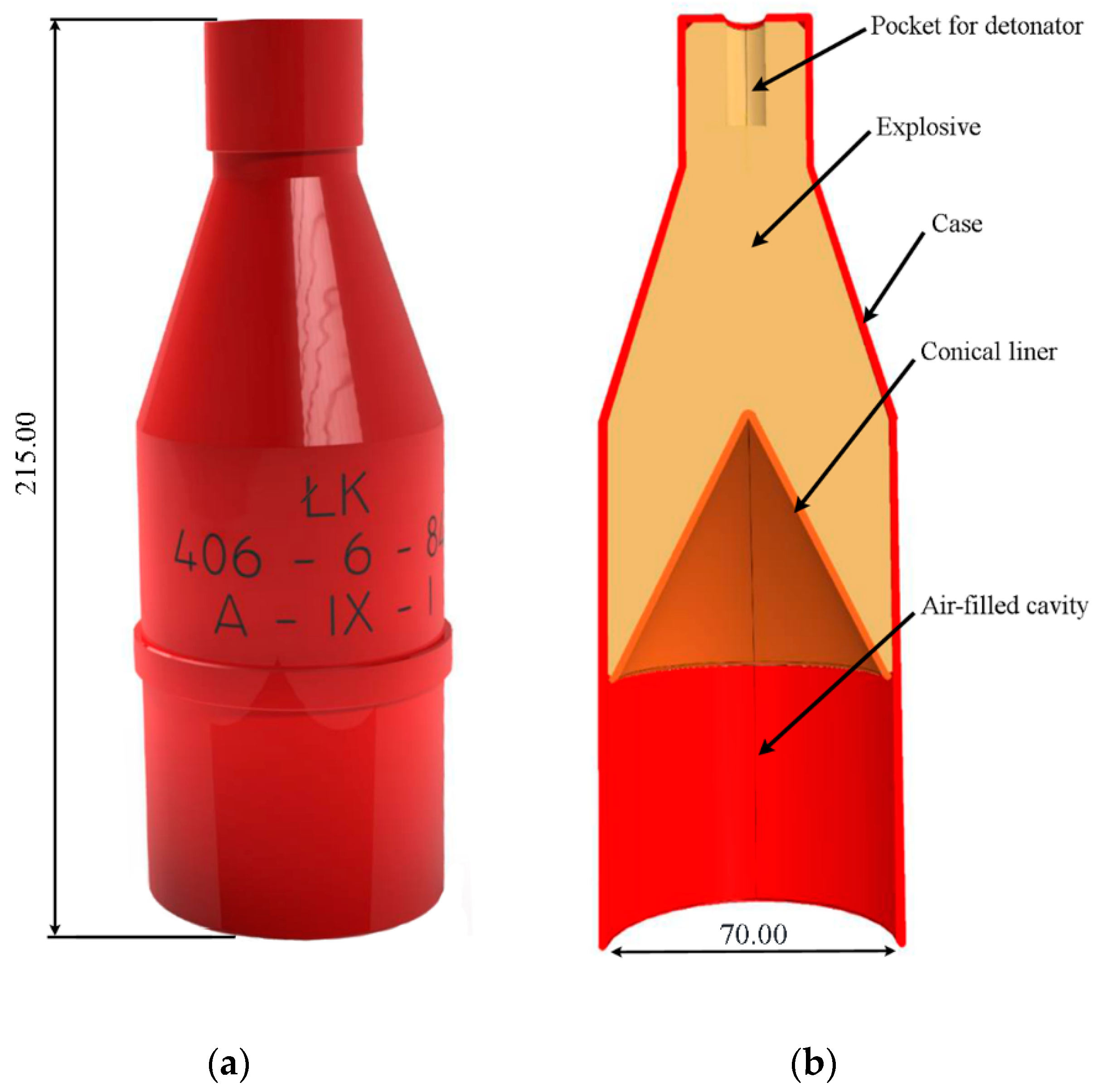
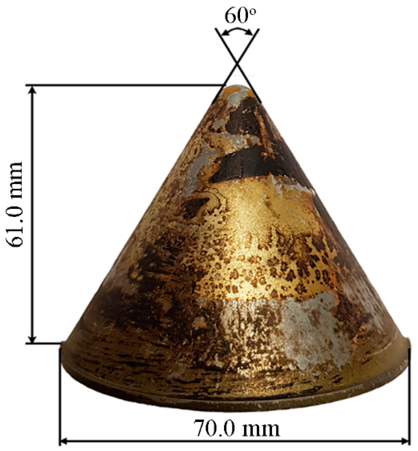
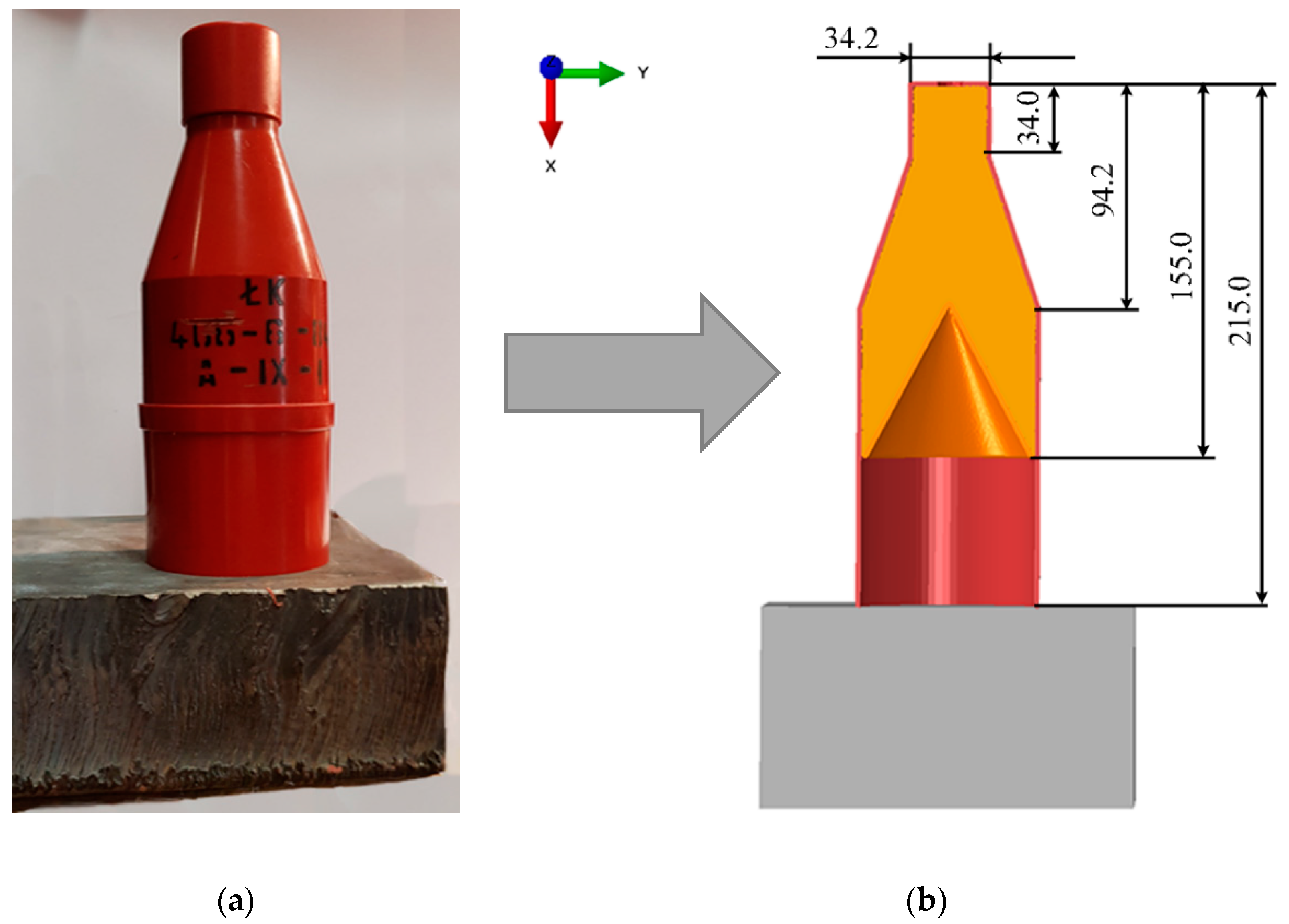
For tests, a typical ŁK charge was used, which is a charge made of explosive crushing material, pressed into a plastic casing and closed with a conical liner. The cumulative liner, with an opening angle of 60°, was made of zinc aluminum alloy (Zn5Al). Below the liner there is a cylindrical spacer sleeve creating an air gap between the charge and the plane on which is placed the ŁK cumulative charge. This distance is 60 mm. The basic data relating to the cumulative charge are shown in Figure 2.
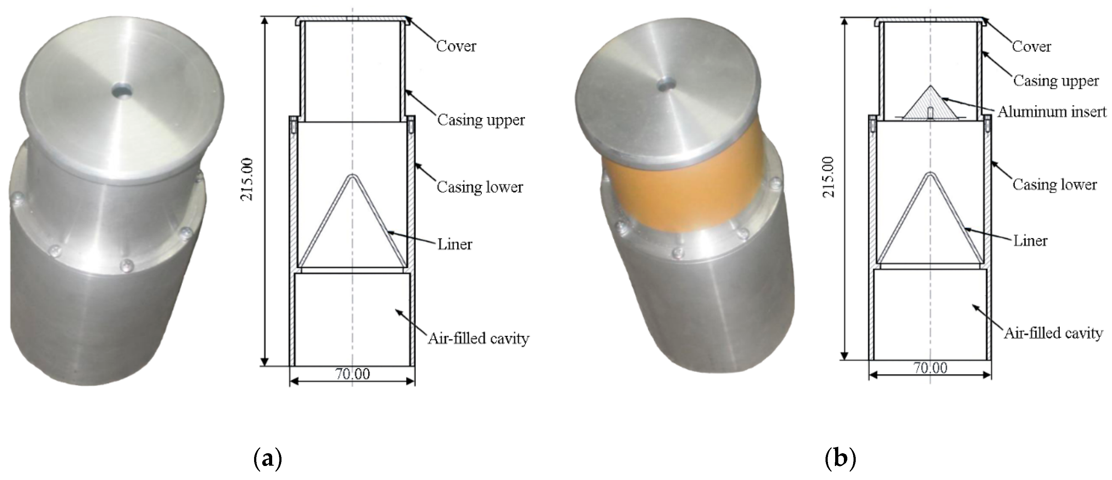
The ŁK charge was filled with explosive hexogen containing 10% granulated TNT, and the so-called “ballast” was made of crystalline pentrite [42]. The explosive can be excited by a fuse or an electric detonator. The ŁK charge was prepared correctly and modified to suit the needs of the test, as presented in Figure 3.
The modification takes into account the criteria for initiating detonation in a given material as well as the penetration depth of the steel shield. Hence, detonations with axially and peripherally induced explosion wave propagation could be performed. The explosive material was modified as the plastic explosive PMW-14.
It should be emphasized that the primary shaped charge (see Figure 2) is a non-dismountable structure. It was impossible to use it in this shape for tests, therefore separable metal casings were used. Metal casings (see Figure 3) were used only because this allowed for the technological possibilities of preparing shaped charges with additional inserts. To be sure of the comparative results, charges were also made in metal casings with axial initiation. It was possible to practically compare their effectiveness with the original ŁK-shaped charge. In the ballistic tests, after the visual inspection, it was assumed that the results did not differ from the assumed ones. Therefore, the impact of the casing on the explosion was ignored, focusing on the explosive, the liner, and additional elements introduced into the shaped charge causing the appropriate orientation of the detonation wave front.

3.2. The Structure of Shaped Charge Tests

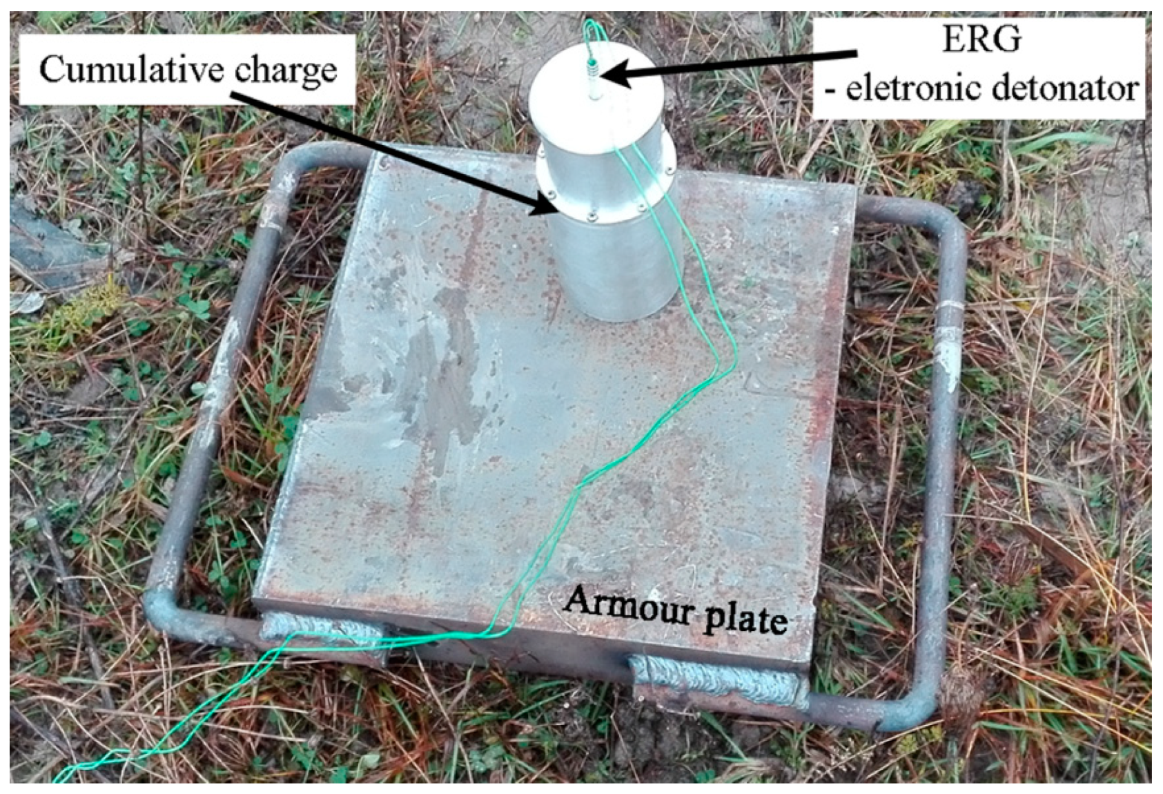
For the purposes of the test, six charges of each type were made. The purpose of this test was to assess the efficiency of charges with two types of detonation initiation. The differences in the detonations process could have influence to characteristics of the detonation wave acting on the liner and finally on the cumulative jet effectiveness. The ARMOX 370T (see Table 1) armored plate (80 mm class 2 and 100 mm class 1 thickness, and dimensions of 1000 × 700 mm) was loaded dynamically with an accumulation charge (70 mm in diameter) according to prepaid charges (see Figure 3).
The cumulative charge used an insert made of the original ŁK, with the geometry shown in Figure 4 and a 2 mm thick liner.
The charges were elaborated with a plastic explosive (PMW-14) containing 84% hexogen (RDX) and 16% binder. This plastic explosive has the following parameters: a density of 1.43 g/cm3, and a detonation speed of 7500 m/s.

3.3. Experimental Results

Six shooting tests were performed, three for each type of charge, as shown in Figure 5.
The shooting resulted in perforations of the steel plates loaded with a cumulative jet (see Figure 6a). Preliminary visual inspection showed that charges with axially (1A, 2A and 3A) induced explosive wave propagation were less effective, which was indicated by the lack of plate puncture—1A and 2A (see Figure 6b).
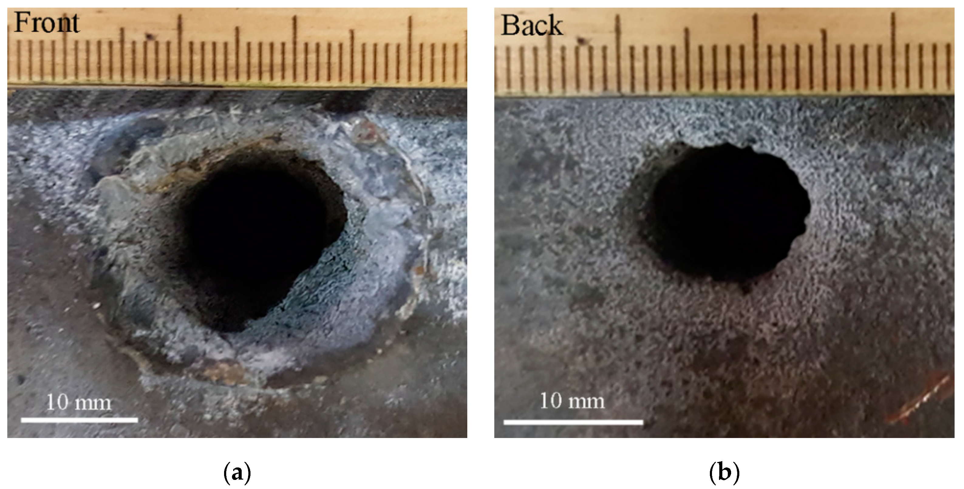
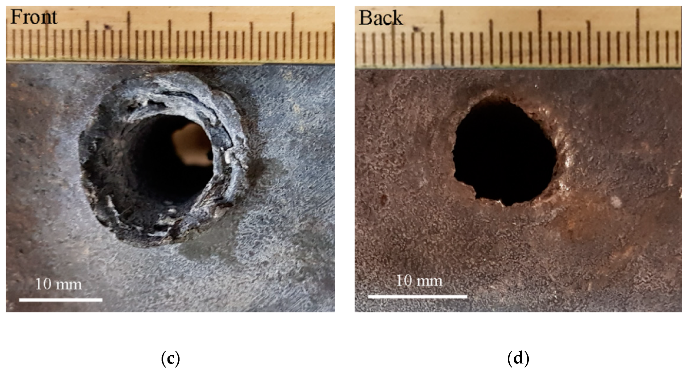
Visual inspection of the armored plate was limited to the evaluation of entry and exit holes from the impact of the cumulative jet on the material of the armored plate being assessed. Such an example is shown in Figure 7, and values are summarized in Table 2. These results indicate that the jet was more regular with the peripheral charge. The diameter of the entrance hole was almost identical to the exit hole (see Figure 7c,d). However, for the axial charge, the jet formation was more disturbed. The entrance hole was significantly larger than the exit hole (see Figure 7a,b).
This was confirmed by the measured diameters of the entry and exit holes (see Table 2) for the two types of shaped charge in 80 mm and 100 mm thick armor plates.

4. Numerical Analysis

4.1. Assumptions for Modelling

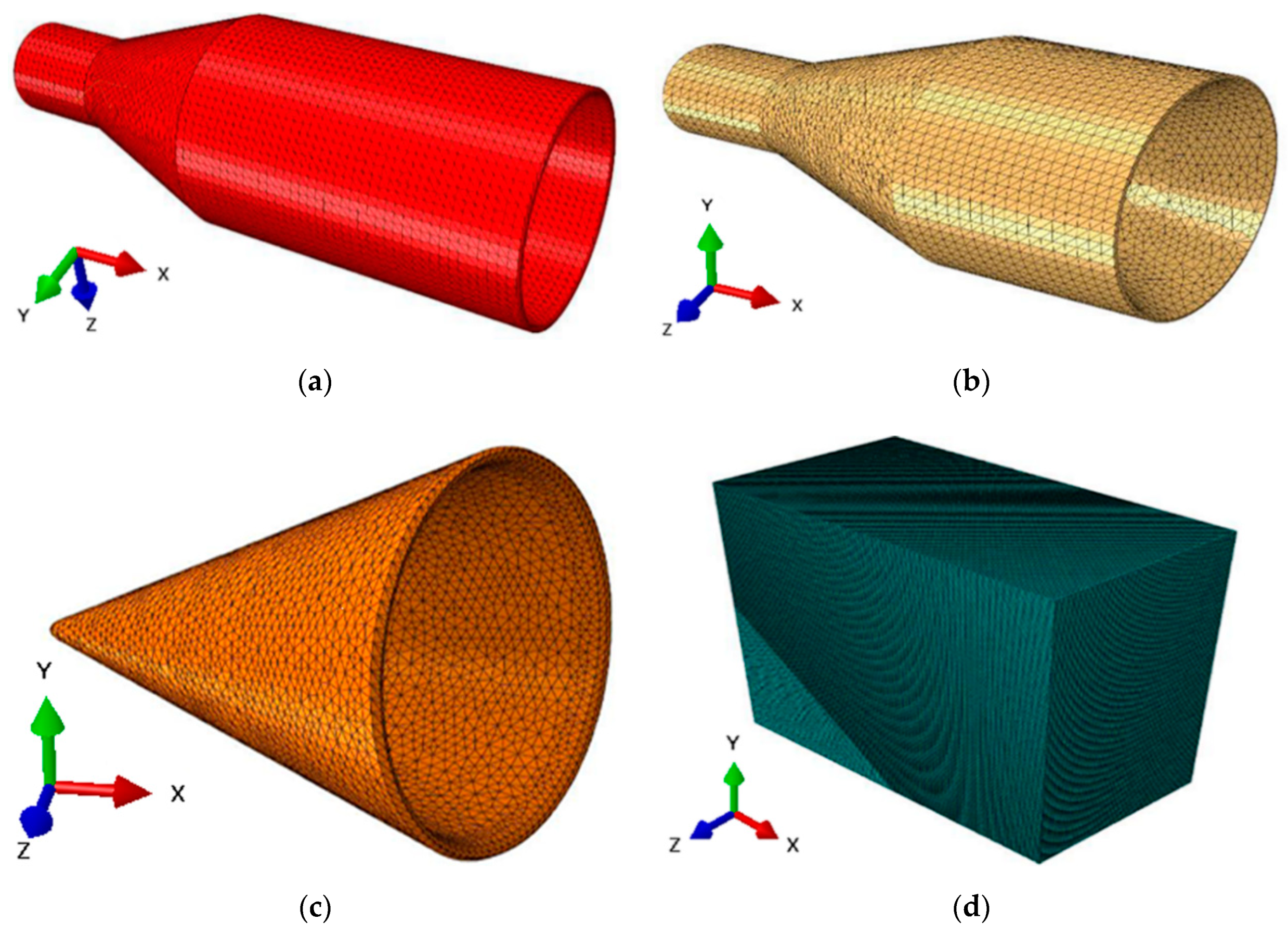
It was necessary to make a geometric model of the charge in question in order to perform the numerical analysis. The geometric model (see Figure 8) was made in Inventor 2018 and then exported in step format to the ABAQUS program, where it was discredited.
The case and the explosive were modeled with 0.5–1.0 mm tetra elements. The cumulative liner with a 60° cone angle was modeled by volume using 0.2 mm tetra-type elements, and 0.5 mm hex elements were used for discrediting the armor plate. Figure 9 displays numerical models of the ŁK charge and armor plate components.
In the modeling, the SPH method described by Lagrange’s equations was adopted because it is a gridless method, which is very efficient for simulating dynamic high speeds. This method involves two stages of approximation. The first stage (kernel approximation) is described by the function:
f ( x ) = Ω f ( x ) W ( x x , h ) d x
where f ( x ) is the approximated value, W is the “smoothing” function representing h, which is the “smoothing length”, and x is the position vector of the particle.
In the second step (particle approximation), the field function f(x) and its derivative Δf(x) are approximated as a weighted sum over surrounding particles within the support area, which can be written as per references [44,45].

4.2. Description of Materials

The equivalent explosive charge in the form of trinitrotoluene (TNT), the so-called TNT equivalent, was assumed in modeling [46,47,48]. This equivalent refers to the determination of such a TNT mass for which the explosion effects are identical to those of the explosive being tested, namely as:
κ T = m T m = E E T
where κT means the TNT equivalent of the explosive in question, m is the mass of the explosive in question, mT is the mass of the reference explosive, E is the explosive energy of the charge in question, and ET is the explosive energy of the referenced explosive.
The JWL mathematical model [34,41,44,45] was assigned, as it allows for determining the pressure according to the following relation:
p = A * ( 1 ω η R 1 ) e x p R 1 η + B * ( 1 ω η R 2 ) e x p R 2 η + ω ρ κ p d
where η is the ratio of the density (ρ) of detonation products to the initial density (ρ0) of the original explosive, κpd is the pre-detonation bulk modulus, and A*, B*, R1, R2 and ω are the fitting coefficients obtained from experiments.
The air properties were described using the Mie–Gruneisen equation [49,50] in accordance with the following relation:
P = p 0 + γ ρ a E 0
where p0 is the initial air pressure, γ is the Gruneisen coefficient, ρa is the density of air, and E0 is the initial internal energy.
The cumulative insert and armor plate are described by the J-C model together with the J-C damage model per [51,52], as follows:
σ = ( A + B ε n ) · [ 1 + C l n ( ε ˙ ε ˙ 0 ) ] · [ 1 ( ( T T 0 T m T 0 ) m ]
ε f = ( D 1 + D 2 e x p D 3 σ * ) · [ 1 + D 4 l n ( ε ˙ ε ˙ 0 ) ] · [ 1 D 5 ( T T 0 T m T 0 ) m ]
where ε is the plastic strain, ε ˙ is the plastic strain rate, ε ˙ 0 is the reference strain rate, T is the current temperature, T0 is the room temperature, Tm is the melting temperature, A, B, C, n and m are the J-C material behavior coefficients, ε f is the plastic strain to fracture, σ * is the equivalent stress, and D1, D2, D3, D4 and D5 are the input constants determined empirically.
The description of material parameters was mainly drawn from data from the literature (see Table 3).

4.3. ŁK Charge Options

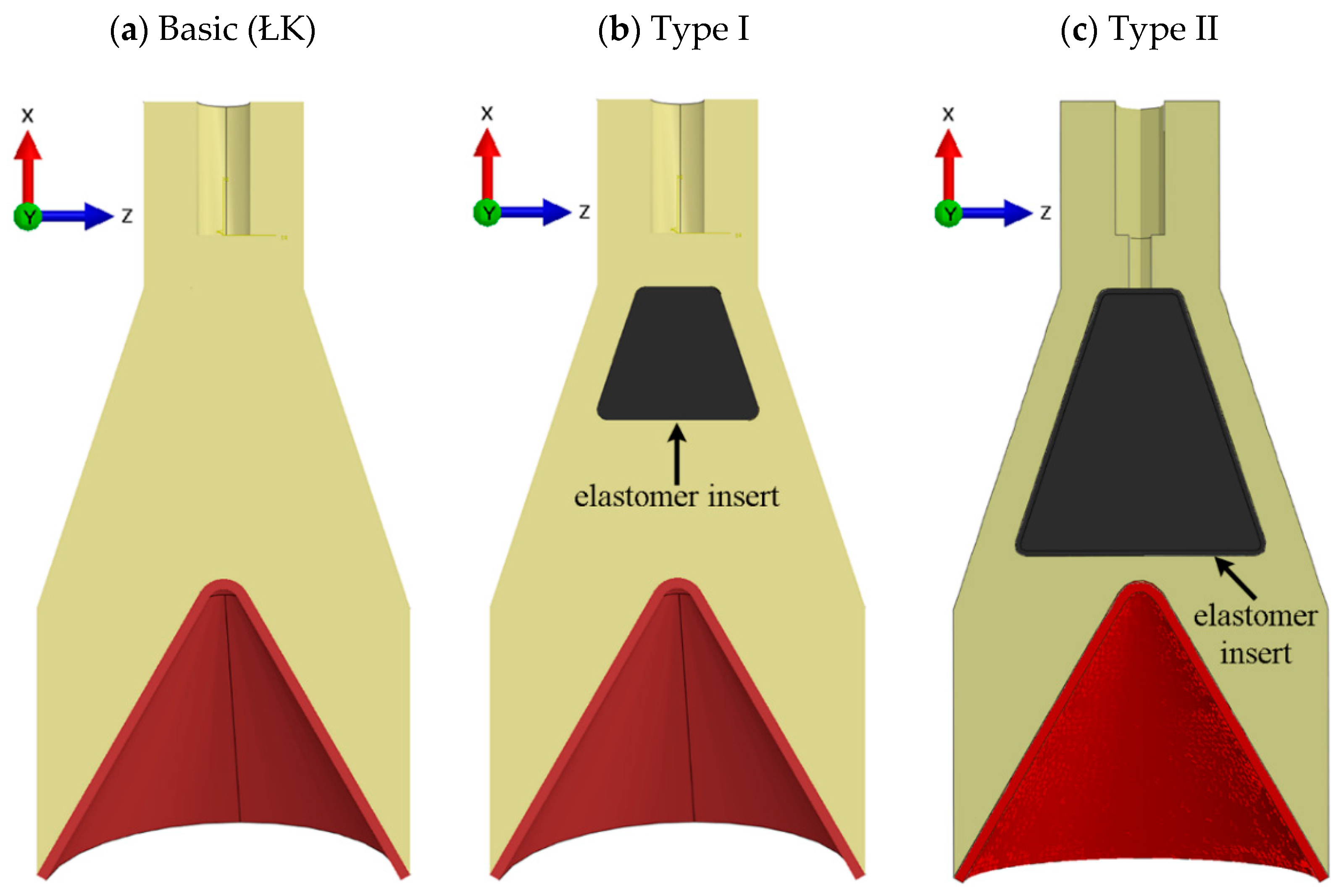
Due to the nature of charge optimization work, the diameter of the base of the coupler remains constant, and we used copper alloy as the liner material. In addition to the basic numerical models for the experimental conditions (see Figure 2), two additional ŁK charge models (see Figure 10) with axially and peripherally induced explosion wave propagation were developed.
An additional insert made of elastomeric material (rubber) was used for peripheral propagation. The material was selected so that the propagation of the detonation wave in the medium caused a greater angle of incidence on the liner, and thus the effect of dividing the forming jet into a slug and a jet was changed. The insert, in the shape of a truncated cone with a broader base directed towards the cumulative core formation, was adopted for the first and second type. The dimensions of these inserts were chosen so as to leave a 10 mm wide explosive at the perimeter and avoid expiration of the detonation propagation. The modified parameters included the height of the insert and the size of the rubber element (see Figure 10).

5. Results and Discussion

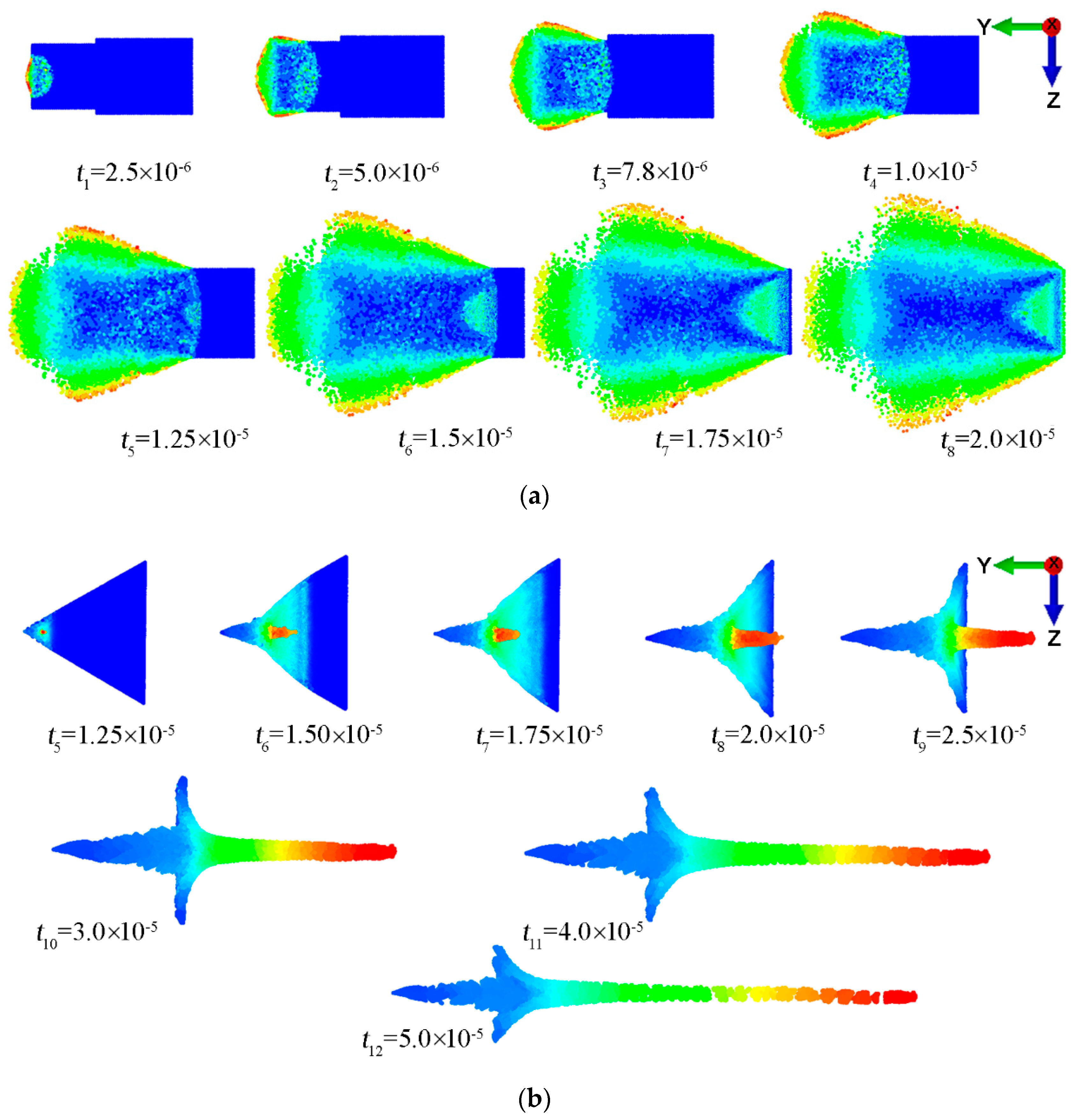
The numerical simulations that we conducted enabled us to analyze cumulative jet formation. In the basic ŁK charge (see Figure 3a), the detonation wave reached the surface perpendicularly to the object. Cumulative jet formation occurred from the detonation wave, which reached the cumulative insert and generate a great number of small incidence angles. Such an arrangement resulted in too short a cumulative jet. The results of this simulation are shown in Figure 11.
Despite its shorter jet, its velocity distribution was linear (see Figure 11b). On the other hand, the phenomenon of liner collapse, determined by the Birkhoff effect, was slightly less favorable [58].
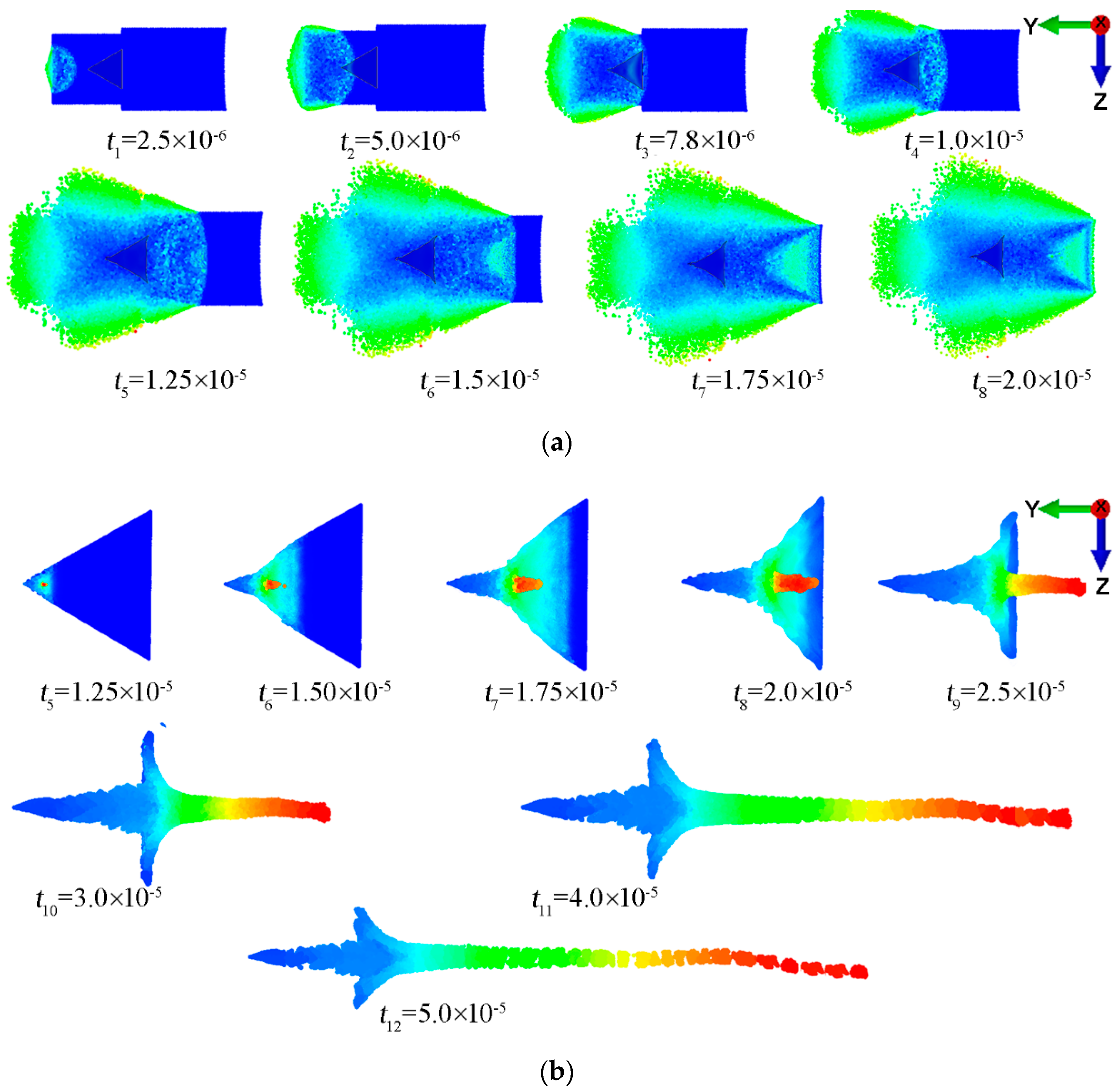
In a charge with an additional insert (see Figure 3b), the charge jet formation parameters improved slightly. The results of this analysis are shown in Figure 12. The numerical simulation results relating to the formation of jets (based on the model assumptions for charges used in the experimental tests) indicated different tendencies in these formations. The axial charge was more stable, but its jet was shorter (see Figure 11b). In the case of a peripheral charge, a lengthening of the jet (see Figure 12b) was caused by a significant difference in velocity between the head and tail of the jet, and in the case of the axial charge, these differences were smaller. They resulted from the different angles of incidence of the detonation wave on the liner. For an axial charge, this angle was smaller than for a peripheral charge. The reliability of the numerical results was verified by evaluating the entry and exit holes of the cumulative jet’s passage in the armored plate. In the experiment, the entry hole average for the axial charge was 22.7 mm, and the exit hole was 15.7 mm. In the case of the peripheral charge, the entry hole average was 13 mm, and the exit hole was 12.5 mm. In the simulation, the entry was 21.8 mm, and the exit was 19.7 mm, but the peripheral charge had a 12.0 mm entry hole and 11.6 mm exit hole, which is a satisfactory result.
The jet formation times were also compared (see Figure 13). As can be seen, in the first phase of jet formation, the addition of an insert into the ŁK charge (see Figure 3b) caused a significant velocity difference, and the liner collapsed for the peripheral charge. It can be assumed that the stagnation point was more favorable for this type of charge. The effectiveness of such a charge is determined by the air gap between the charge and the obstacle. In this case, the gap was 60 mm. As can be seen, axial charges, due to the higher focusing, resulted in larger entry hole diameters in the pierced armor plate.
The jets of these charges were shorter than those of the peripheral charges, and in two cases, no perforation was noted (see Table 2). In the peripheral charges, this jet had a lower focal length, which made it more effective, despite the fact that in the final phase, the jet lost its axisymmetric parameters. Ultimately, the jet velocities were 7.8 km/s for the axial charge and 7.58 km/s for the peripheral charge.
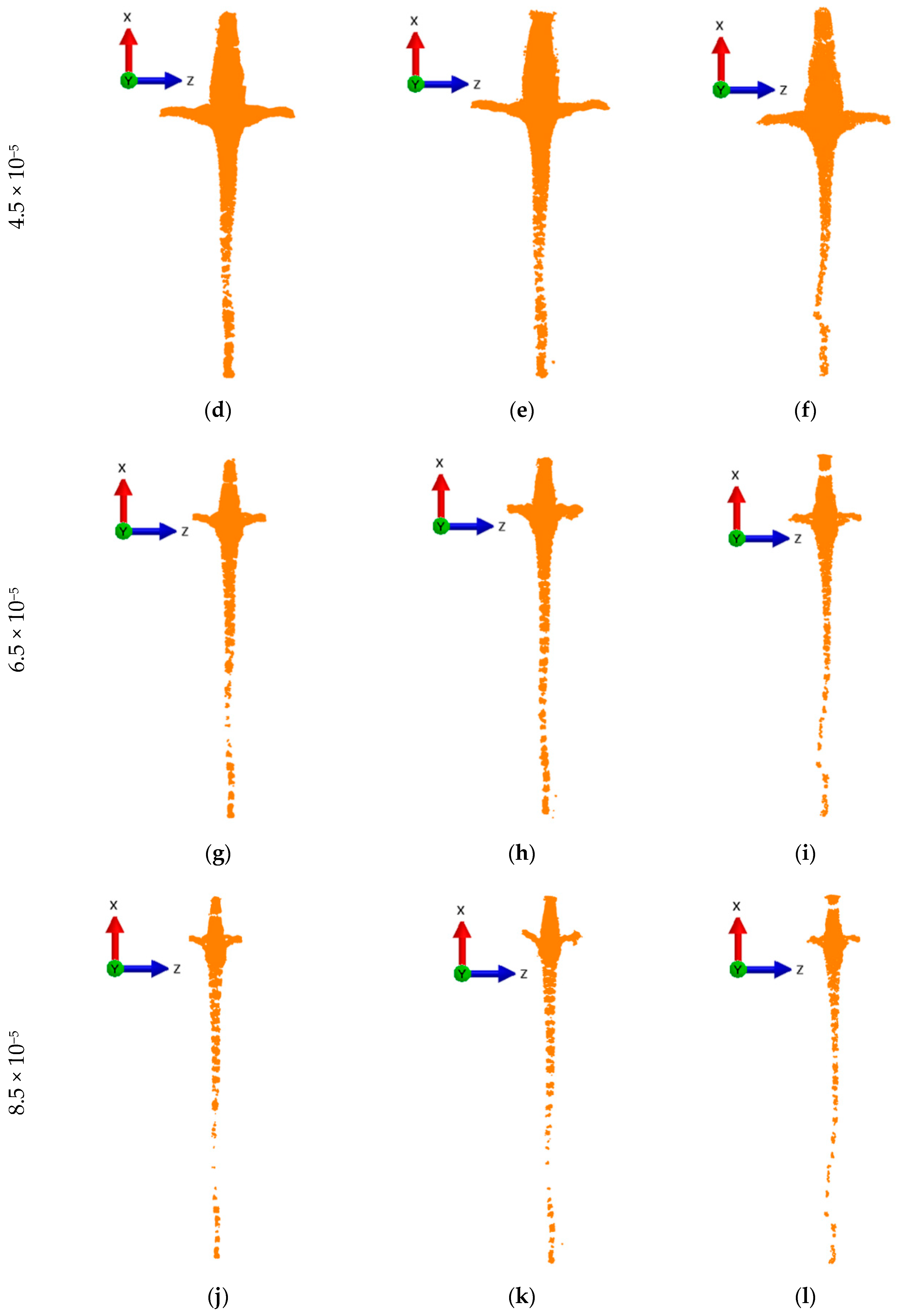
In the following part, the explosive charge was modified in order to extend the range of incidence angles of the detonation wave on the insert and increase jet formation. The results from the studied numerical models are presented in the figure below (see Figure 14).
Some differences can be seen among the stages of cumulative jet formation shown for individual types of charges. The basic ŁK charge was assessed as being the most stable in the range of axial formation of the cumulative jet. Type I and II charges showed, in the final phase, a tendency towards jet deviation. It is evident from our analysis that the jet of the basic ŁK charge was more effective. Nevertheless, based on a detailed analysis of individual time steps of jet formation in the simulation for type I and II charges, it was concluded that the division of the forming jet into a slug and a jet is more advantageous for modified charges. The type II charge is slightly more favorable because the insert (which separates the inner part passing into the jet from the outer one passing into the slug) causes the jet to be amplified, and thus its depth of focus is the most advantageous.
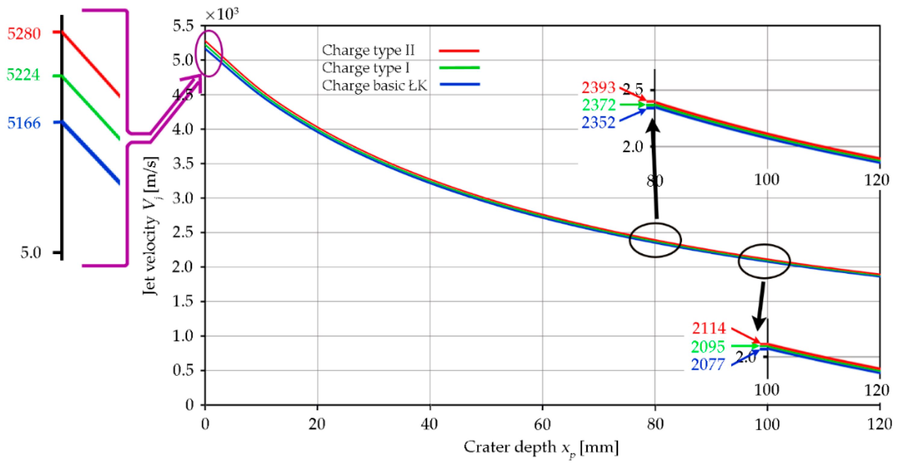
In the simulation for the basic ŁK charge, the jet velocity was 5166 m/s for the type I charge 5224 m/s, and for the type II charge it was 5280 m/s. Due to the limitations of the X-ray registration of the cumulative jet formation, the estimation of the relationship between jet velocity and penetration depth of the armor plate was based on numerical analysis. Example results were obtained from dependencies (4) and (6), as shown in Figure 15.
The estimates of jet velocity for the basic ŁK charge (see Figure 10) after piercing an 80 mm thick partition are at the level of 2352.2 m/s, and with a 100 mm partition, this value was 2077.5 m/s. With charge modifications, the speed of the jet increased slightly. As shown, the use of an additional insert makes sense despite the slight increase in jet velocity. For identify the phenomena of the jet collapsing region two configurations in the numerical simulations (see Figure 16) were elaborated.
There is clearly a smaller percentage of collapsing liner in the jet formation for the axial load (see Figure 16a) than for the peripheral load (see Figure 16b).
Nevertheless, attention should be paid to further modifications that should be made when selecting an appropriate liner material.
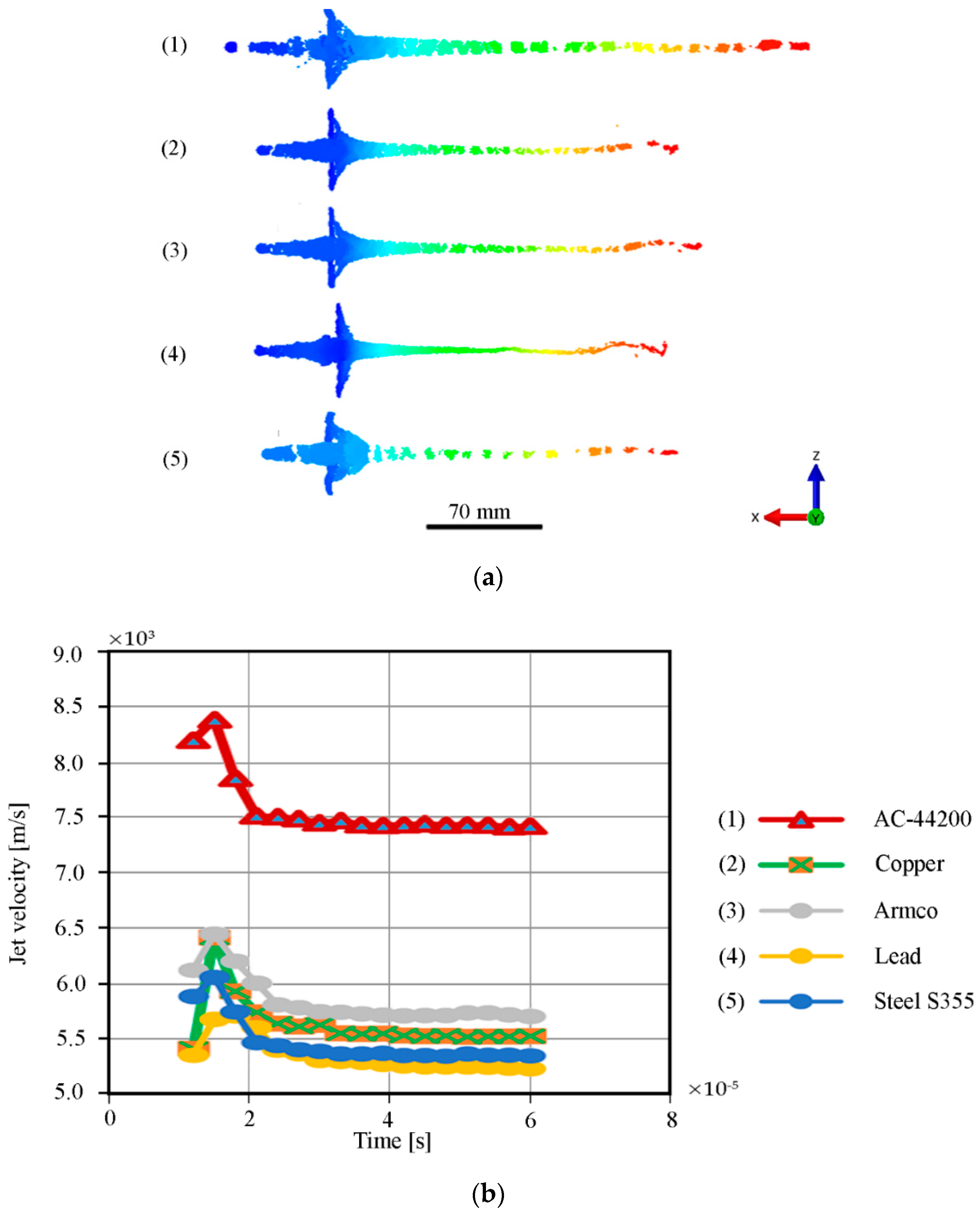
In the last step of this analysis, the influence of the insert material on the velocity of cumulative jet formation and its stability was investigated. Figure 17 displays exemplary results from numerical simulations.
As indicated in the diagram (see Figure 17a), for all types of cumulative insert materials tested, the best results were obtained with the material made of AC-44200 alloy. The jet showed a perfectly axial symmetrical geometry. Materials such as copper and Armco alloy showed the same speeds in the initial phase, while in the next part of the jet formation, the copper alloy gave way to Armco. The differences were approximately 300 m/s. Lead-based inserts showed the lowest jet speeds.

6. Conclusions

This article presents the results of modeling the cumulative jet for the ŁK charge. The SPH method enabled us to obtain accurate results from modeling cumulative core formation with a relatively fast calculation time. The results from the numerical simulation (see Figure 13) of the jet velocity showed a correlation with the results described in the literature. As indicated, the jet front reaches speeds between 7 and 10 km/s (see Figure 1). In the case of numerical simulation, a speed is included in this range. It has been shown that the modification of the ŁK charge had a positive effect on jet amplification, with an inevitable collapse in the final stage of formation (see Figure 14). This is also due to the increased initiation of the cumulative jet’s velocity, which indicated better parameters for the peripheral charge. The above was also confirmed in the experiment. Numerical tests and theoretical analysis (see Section 2) show that the jet still retains its ability to penetrate after penetrating the shield. It follows that this ŁK charge can effectively pierce shields of this type with a thickness of more than three calibers. It has been observed that peripherally initiated charges have a positive effect on the jet growth in the procession of the collapsing liner. Moreover, it was confirmed with the literature data that the material for the liner is of significant importance in achieving the velocity of the cumulative jet (see Figure 17). Summarizing the presented results of modeling the efficiency of the jet, based on numerical methods applied to the ŁK-shaped charge, confirms the correct direction of the research. The results presented, which are mostly based on simulation studies, will be validated in multi-variant ballistic tests, as well as in the material examination of the liner in further work.

Author Contributions

Conceptualization, K.J., A.K. and D.P.; methodology, K.J., A.K., M.B. (Miroslaw Bocian) and M.B. (Marcin Bajkowski); software, D.P., M.B. (Miroslaw Bocian) and M.M.; validation, M.B. (Marcin Bajkowski) and D.P.; formal analysis, A.K., K.J., M.B. (Miroslaw Bocian), D.P. and J.S.; investigation, K.J., J.S. and D.P.; resources, K.J., M.B. (Marcin Bajkowski) and M.M.; data curation, A.K., K.J., D.P. and M.B. (Miroslaw Bocian); writing—original draft preparation, K.J., D.P. and A.K.; writing—review and editing, M.M., M.B. (Marcin Bajkowski) and M.B. (Miroslaw Bocian); visualization, A.K., K.J., J.S. and D.P.; supervision, K.J., M.B. (Marcin Bajkowski) and M.M.; project administration, D.P., A.K. and M.B. (Miroslaw Bocian); funding acquisition, M.B. (Marcin Bajkowski), K.J. and M.M. All authors have read and agreed to the published version of the manuscript.

Funding

This research was funded by the National Centre for Research and Development of Poland, grant No. TECHMATSTRATEG 2/410049/12/NCBR/2019.

Acknowledgments

Calculations have been carried out in Wroclaw Centre for Networking and Supercomputing (http://www.wcss.pl), grant No. 452.

Conflicts of Interest

The authors declare no conflict of interest.

References

  1. Austin, C.F. Lined-Cavity Shaped Charges and Their Use in Rock and Earth Materials; Bulletin 59; New Mexico Institute Mining and Technology, State Bureau of Mines and Mineral Research: Socorro, NM, USA, 1959; Available online: https://geoinfo.nmt.edu/publications/monographs/bulletins/downloads/69/Bulletin69.pdf (accessed on 20 January 2020).
  2. Cheng, X.; Huang, G.; Liu, C.; Feng, S. Design of a novel linear shaped charge and factors. Appl. Sci. 2018, 8, 1863. [Google Scholar] [CrossRef] [Green Version]
  3. Bohanek, V.; Dobrilović, M.; Škrlec, V. The efficiency of linear shaped charges. Tehnički Vjesnik 2014, 21, 525–531. [Google Scholar]
  4. Magier, M.; Burian, W.; Rotkegel, M.; Szymala, J. Experimental analysis of the concrete penetration by using warheads from demobilized ammunition. Key Eng. Mater. 2016, 715, 243–248. [Google Scholar] [CrossRef]
  5. Kennedy, D.R. History of the Shaped Charge Effect, the First 100 Years; AD-A220 095; U. S. Department of Commerce: Washingdon, DC, USA, 1983.
  6. Walters, W.P.; Zukas, J.A. Fundamentals of Shaped Charges; Wiley: New York, NY, USA, 1989. [Google Scholar]
  7. Balagansky, I.A.; Bataev, A.A.; Bataev, I.A. Explosion Systems with Inert High-Modulus Components; Wiley: Hoboken, NJ, USA, 2019. [Google Scholar]
  8. Wojewodka, A.; Belzowski, J.; Witkowski, T. Shaped charge and numerical modeling of their detonation. Chemik 2010, 64, 25–32. [Google Scholar]
  9. Lavrent’ev, M.A. Cumulative charge and the principles of its operation. Math Net. Ru 1957, 12, 41–56. Available online: http://www.mathnet.ru/links/644214662b2c98a79b446b5f0cc6a666/rm7663.pdf (accessed on 15 September 2020).
  10. Birkhoff, G.; MacDougall, D.; Pugh, E.; Taylor, G. Explosive with lined cavities. J. Appl. Phys. 1948, 19, 563–582. [Google Scholar] [CrossRef]
  11. Birkhoff, G.; Zarantonello, E.H. Jets, Wakes and Cavities; Academic Press: New York, NY, USA, 1957. [Google Scholar]
  12. Minin, I.V.; Minin, O.V. Physics of hypercumulation: Jet formation in shaped charge and ablatively-driven implosion of hollow cones. Int. Lett. Chem. Phys. Astron. 2014, 22, 76–86. [Google Scholar] [CrossRef] [Green Version]
  13. Chou, P.C.; Carleone, J.; Karpp, R.R. Criteria for jet formation from impinging shells and plates. J. Appl. Phys. 1976, 47, 2975–2981. [Google Scholar] [CrossRef]
  14. Nariman-Zadeh, N.; Darvizeh, A.; Darvizeh, M.; Gharababaei, H. Modelling of explosive cutting process of plates using GMDH-type neural network and singular value decomposition. J. Mater. Process. Tech. 2002, 128, 80–87. [Google Scholar] [CrossRef]
  15. Hu, N.; Zhu, X.; Chen, C. Theoretical calculation of the fragment initial velocity following aerial explosion of the cylindrical warhead with two terminals. IOP Conf. Ser. Mater. Sci. Eng. 2017, 274, 012049. [Google Scholar] [CrossRef] [Green Version]
  16. Wang, Z.; Jiang, J.-W.; Wang, S.-Y.; Liu, H. Jet formation and penetration study of double-layer shaped charge. J. Energetic Mater. 2018, 36, 152–168. [Google Scholar] [CrossRef]
  17. Wiśniewski, A.; Podgórzak, P. Research results on precursor of the tandem shaped charge projectile model. Probl. Tech. Uzbroj. 2005, 94, 31–38. [Google Scholar]
  18. Kurzawa, A.; Pyka, D.; Bocian, M.; Jamroziak, K.; Sliwinski, J. Metallographic analysis of piercing armor plate by explosively formed projectiles. Arch. Civ. Mech. Eng. 2018, 8, 1686–1697. [Google Scholar] [CrossRef]
  19. Novotney, D.; Mallery, M. Historical development of linear shaped charge. AIAA 2007, 5141. [Google Scholar] [CrossRef]
  20. Ayisit, O. The influence of asymmetries in shaped charge performance. Int. J. Impact. Eng. 2008, 35, 1399–1404. [Google Scholar] [CrossRef]
  21. Hokamoto, K.; Raghukandan, K. Explosion Shock Waves and High Strain Rate Phenomena; Materials Research Forum LLC: Millersville, PA, USA, 2019. [Google Scholar]
  22. Wang, H.; Guo, H.; Geng, B.; Yu, Q.; Zheng, Y. Application of PTFE/Al reactive materials for double-layered liner shaped charge. Materials 2019, 12, 2768. [Google Scholar] [CrossRef] [Green Version]
  23. Saran, S.; Ayisit, O.; Yavuz, M.S. Experimental investigations on aluminum shaped charge liners. Proc. Eng. 2013, 58, 479–486. [Google Scholar] [CrossRef] [Green Version]
  24. Naeem, K.; Hussain, A.; Abbas, S. A review of shaped charge variables for its optimum performance. Eng. Tech. Appl. Sci. Res. 2019, 9, 4917–4924. [Google Scholar]
  25. Abdo, G.M.; Elshenawy, T. Density effect of the compacted copper-tungsten shaped charge powder liners on its penetration performance. J. Powder. Metall. Min. 2017, 6, 172. [Google Scholar] [CrossRef]
  26. Wenlong, X.; Cheng, W.; Dongping, C. Formation of a bore-center annular shaped charge and its penetration into steel targets. Int. J. Impact Eng. 2019, 127, 122–134. [Google Scholar] [CrossRef]
  27. Xu, W.; Wang, C.; Chen, D. The jet formation and penetration capability of hyperveloci-ty shaped charges. Int. J. Impact Eng. 2019, 132, 103337. [Google Scholar] [CrossRef]
  28. Lee, S.; Kim, J.; Kim, S.; Lee, S.; Jeong, J.; Lee, C. Performance comparison of double-layer liner for shaped charge fabricated using kinetic spray. J. Therm. Spray. Tech. 2019, 28, 484–494. [Google Scholar] [CrossRef]
  29. Wang, C.; Ding, J.; Zhao, H. Numerical Simulation on jet formation of shaped charge with different liner materials. Def. Sci. J. 2015, 65, 279–286. [Google Scholar] [CrossRef]
  30. Elshenawya, T.; Elbeihb, A.; Klapötkec, T.M. A numerical method for the determination of the virtual origin point of shaped charge jets instead of using flash X-ray radiography. J. Energetic Mater. 2018, 36, 127–140. [Google Scholar] [CrossRef]
  31. Hussain, G.; Hameed, A.; Hetherington, J.G.; Barton, P.C.; Malik, A.Q. Hydrocode simulation with modified Johnson-Cook model and experimental analysis of explosively formed projectiles. J. Energetic Mater. 2013, 31, 143–155. [Google Scholar] [CrossRef]
  32. Ou, J.H.; Ou, J.B.; Jhu, Y.J. The design and analysis for shaped charge liner using Taguchi method. Int. J. Mech. 2014, 8, 53–61. [Google Scholar]
  33. Steinberg, D.J.; Lund, C.M. A constitutive model for strain rates from 10-4 to 106 s-1. J. Appl. Phys. 1989, 65, 1528. [Google Scholar] [CrossRef]
  34. Baudin, G.; Serradeill, R. Review of Jones-Wilkins-Lee equation of state. EPJ Web Conf. 2010, 10, 00021. [Google Scholar] [CrossRef] [Green Version]
  35. Downes, D.; Bouamoul, A.; Ensan, M.N.; Baillargeon, Y. Development of an efficient numerical model for shaped charge analysis. J. Def. Mod. Simul. Appl. Met. Tech. 2016, 13, 355362. [Google Scholar] [CrossRef]
  36. Zhang, Z.; Jin, W.-W. Finite element modeling of the shaped charge jet and design of the reusable perforating gun. Pet. Sci. 2020, 17, 1389–1399. [Google Scholar] [CrossRef]
  37. Yi, J.; Wang, Z.; Yin, J.; Zhang, Z. Simulation study on expansive jet formation characteristics of polymer liner. Materials 2019, 12, 744. [Google Scholar] [CrossRef] [PubMed] [Green Version]
  38. Feng, D.L.; Liu, M.B.; Li, H.Q. Smoothed particle hydrodynamics modeling of linear shaped charge with jet formation and penetration effects. Comput. Fluids. 2013, 86, 77–85. [Google Scholar] [CrossRef] [Green Version]
  39. Zhang, Z.; Wang, L.; Silberschmidt, V.V. Damage response of steel plate to underwater explosion: Effect of shaped charge liner. Int. J. Impact. Eng. 2017, 103, 38–49. [Google Scholar] [CrossRef] [Green Version]
  40. Held, M. Time distance diagram of the jet initiation of covered high explosive charges. Int. J. Impact. Eng. 2007, 34, 702–707. [Google Scholar] [CrossRef]
  41. Ding, L.; Tang, W.; Ran, X. Simulation study on jet formability and damage characteristics of a low-density material liner. Materials 2018, 11, 72. [Google Scholar] [CrossRef] [PubMed] [Green Version]
  42. Industry standard: BN-72/6096-01. Open type directional cumulative hexogen charges HT/P-26 Z and HT/P-32. (In Polish). Available online: http://bc.pollub.pl/Content/3037/PDF/BN_72_6096_01.pdf (accessed on 20 January 2020).
  43. Data Sheet. Armox 370T, ARMOX® Protection Plate; SAAB: Stockholm, Sweden, 2017. [Google Scholar]
  44. Liu, G.R.; Liu, M.B. Smoothed Particle Hydrodynamics; A Meshfree Particle Method; World Scientific: London, UK, 2003. [Google Scholar]
  45. Zhang, Z.; Wang, C.; Xu, W.; Hu, H. Penetration of annular and general jets into underwater plates. Comp. Partical Mech. 2020, 1–8. [Google Scholar] [CrossRef]
  46. Panowicz, R.; Konarzewski, M.; Trypolin, M. Analysis of criteria for determining a TNT equivalent. Stroj. Vestn. J. Mech. E. 2017, 63, 666–672. [Google Scholar] [CrossRef]
  47. Handley, C.A.; Lambourn, B.D.; Whitworth, N.J.; James, H.R.; Belfield, W.J. Under-standing the shock and detonation response of high explosives at the continuum and meso scales. Appl. Phys. Rev. 2018, 5, 011303. [Google Scholar] [CrossRef]
  48. Xiao, W.; Andrae, M.; Gebbeken, N. Air blast TNT equivalence concept for blast-resistant design. Int. J. Mech. Sci. 2020, 185, 105871. [Google Scholar] [CrossRef]
  49. Kucewicz, M.; Baranowski, P.; Malachowski, J.; Trzcinski, W.; Szymanczyk, L. Numerical modelling of cylindrical test for determining Jones–Wilkins-Lee equation parameters. In Proceedings of the 14th International Scientific Conference: Computer Aided Engineering. CAE 2018. Lecture Notes in Mechanical Engineering; Rusiński, E., Pietrusiak, D., Eds.; Springer: Cham, Switzerland, 2019; pp. 338–394. [Google Scholar]
  50. Shin, Y.S.; Lee, M.; Lam, K.Y.; Yeo, K.S. Modeling mitigation effects of watershield on shock waves. Shock Vib. 1998, 5, 225–234. [Google Scholar] [CrossRef] [Green Version]
  51. Malachowski, J.; Mazurkiewicz, P. Elastic-plastic Half Cylidrical Surface Response under Blast Loading. CMM-2011–Computer Methods in Mechanics. 2011. Available online: https://pdfs.semanticscholar.org/1a60/2fd261123bb1f40f4d3ba6f92b49e42c5977.pdf (accessed on 20 January 2020).
  52. Kurzawa, A.; Pyka, D.; Jamroziak, K.; Bocian, M.; Sliwinski, J. Experimental and metallographic analysis of the energy absorbing shield subjected to the EFP impact. AIP Conf. Proc. 2019, 2078, 020035. [Google Scholar] [CrossRef]
  53. Jach, K. Computer Modeling of Dynamic Body Interactions Using a Smoothed Particles Hydrodynamics; PWN: Warsaw, Poland, 2001. (In Polish) [Google Scholar]
  54. Sliwinski, J.; Ludas, M.; Kosnik, S.; Pyka, D.; Jamroziak, K. Investigations of the Detonation Wave Propagation Process in the ŁK Cumulative Charge; Research report; Ammunition Testing Laboratory: Wroclaw, Poland, 2016; Unpublished materials. [Google Scholar]
  55. Panowicz, R.; Konarzewski, M. Influence of imperfect position of a striker and input bar on wave propagation in a Split Hopkinson Pressure Bar (SHPB) Setup with a pulse-shape technique. Appl. Sci. 2020, 10, 2423. [Google Scholar] [CrossRef] [Green Version]
  56. Xu, Y.J.; Wang, Z.J.; Wu, G.D.; Yin, J.P.; Dong, F.D.; Jin, Y.X. Density effect of PTFE-copper powder metallurgy liner material on the perforation performance of shaped charge jets. Strength Mater. 2019, 51, 616–623. [Google Scholar] [CrossRef]
  57. Kurzawa, A.; Pyka, D.; Jamroziak, K.; Bocian, M.; Kotowski, P.; Widomski, P. Analysis of ballistic resistance of composites based on EN AC-44200 aluminum alloy reinforced with Al2O3 particles. Compos. Struct. 2018, 201, 834–844. [Google Scholar] [CrossRef]
  58. Curtis, J.P.; Kelly, R.J. Circular streamline model of shaped-charge jet and slug formation with asymmetry. J. Appl. Phys. 1994, 75, 7700–7709. [Google Scholar] [CrossRef]
Figure 1. Speeds of the resulting individual components of the collapsing liner.
Applsci 10 06742 g001
Figure 2. General view of the ŁK cumulative charge: (a) 3D view; (b) cross-sectional view.
Applsci 10 06742 g002
Figure 3. Cumulative charges prepared for testing: (a) axial of cumulative charge; (b) peripheral of cumulative charge.
Applsci 10 06742 g003
Figure 4. Liner geometry.
Applsci 10 06742 g004
Figure 5. A way of loading the armor plate with a cumulative charge.
Applsci 10 06742 g005
Figure 6. Plate class 1 after firing with ŁK charge: (a) holes after axial (1A, 2A and 3A) and peripheral charges (1P, 2P and 3P); (b) no perforation for 1A and 2A shots.
Applsci 10 06742 g006
Figure 7. Examples of results of the entry and the exit openings after a shot with a ŁK type shaped charge: (a) hole of axial charge entrance; (b) hole of axial charge exit; (c) hole of peripheral charge entrance; (d) hole of peripheral charge exit.
Applsci 10 06742 g007aApplsci 10 06742 g007b
Figure 8. Models of the ŁK charge: (a) physical model; (b) geometrical model.
Applsci 10 06742 g008
Figure 9. Numerical models of the ŁK charge components: (a) plastic case; (b) explosive; (c) cumulative liner; (d) armor plate.
Applsci 10 06742 g009
Figure 10. Models for the simulation analysis of the ŁK charge.
Applsci 10 06742 g010
Figure 11. Stages of formation jet of the axial charge for individual time steps: (a) process of propagation of explosion detonation wave; (b) stages of the jet’s formation in the liner.
Applsci 10 06742 g011
Figure 12. Stages of jet formation of the peripheral charge for individual time steps: (a) the process of propagation of an explosion detonation wave onto an additional insert in order to increase the angles of incidence on the liner; (b) stages of the jet formation in main liner.
Applsci 10 06742 g012
Figure 13. Jet velocities for two types of shaped charge.
Applsci 10 06742 g013
Figure 14. Time steps of the three types of ŁK charges analyzed: (ac) time step for t = 2.5 × 10⁻⁵; (df) time step for t = 4.5 × 10⁻⁵; (gi) time step for t = 6.5 × 10⁻⁵; (jl) time step for t = 8.0 × 10⁻⁵.
Applsci 10 06742 g014aApplsci 10 06742 g014b
Figure 15. Dependence of the jet velocity on the armor plate penetration depth.
Applsci 10 06742 g015
Figure 16. Qualitative comparison of the effect of the collapsing liner material on the formation of the slug and the jet. (a) the jet from detonation of an axial charge; (b) the jet from detonation of an peripheral charge.
Applsci 10 06742 g016
Figure 17. Simulations of cumulative charges with liners of different material structures: (a) formation of the cumulative jet; (b) jet velocities for different insert materials.
Applsci 10 06742 g017
Table 1. Mechanical properties [18,43].
Specimens Thickness
(mm)
Yield Strength
Rp02 (MPa)
Tensile Strength
Rm (MPa)
Hardness
(HBW)
Charpy-V
(J)
Elongation A5
(min %)
Elongation A50
(min %)
plate 80800900–1100280–33060 J/−40 °C1315
plate 100--300–35040 J/−40 °C--
Table 2. A list of the diameters of the entrance and exit holes from a shaped charge.
Specimens
[mm]
Axial ChargesPeripheral Charges
1A2A3A1P2P3P
plate 100front21.222.723.012.914.113.2
backNoneNone14.812.013.412.9
plate 80front22.023.024.012.012.513.0
back15.316.015.011.712.312.8
None—no perforation.
Table 3. Material constants.
Explosive
ρ*DPCJA*B*R1R2ωκpdSources
(kg/m3)(m/s)(GPa)(GPa)(GPa)(-)(-)(-)(GPa)
TNT1730819328.00609.0013.004.501.400.259.00[48,53]
Liner Material
ρEνABCnmSources
(kg/m3)(GPa)(-)(MPa)(MPa)(-)(-)(-)
Zn5Al7010980.301802000.0080.1001.0[53,54]
Cooper89601.280.3680500-0.6051.00[55,56]
AC-442002730700.331103300.0080.1001.00[57]
Steel S35578202100.3580716600.0080.1001.00[26,53]
Armco78702100.372334600.0470.3200.55[53]
Lead11,3001150.4224400.0100.5001.00[53]
Elastomer1.2000.010.491020---[53,54]
Note: ρ* is the density of high explosives; D is the velocity of detonation; PCJ is the Chapman–Jouguet pressure; A*, B*, R1 and R2 are parameters; ω is the Gruneisen parameter; κpd is the pre-detonation bulk modulus; ρ is the density of material insert; E is the Young’s modulus; ν is the Poisson’s ratio; A is the yield strength of the material; B is the strain hardening constant; C is the strengthening coefficient of strain rate; n is the hardening exponent; m is the thermal softening exponent.