Abstract
Composite materials have attracted significant attention with regard to the manufacturing of structures that require weight reduction, such as automobiles and aircraft, because they are more resistant to corrosion and fatigue than conventional metal materials. However, such materials exhibit a reliability degradation problem, i.e., their mechanical and physical properties deteriorate due to the occurrence of delamination and voids. Ultrasonic inspection methods have been widely applied for nondestructive detection of such defects in structures; however, the application of these approaches has been impeded due to high anisotropy and acoustic attenuation. In addition, the existing ultrasonic inspection methods require considerable time and cost for the inspection of large materials or structures. These problems were addressed in this study by developing an automatic ultrasonic inspection system; this was achieved by adopting a squirter-type water injection device, which uses a multi-joint robot and the through-transmission ultrasonic method. In addition, a software program to correct axis misalignment was developed and verified to solve the deterioration in defect detectability and accuracy that was caused by axis misalignment, which may occur during the use of the developed system. This development was accomplished after measuring the coordinates of the deformed mechanical part using a three-dimensional laser measuring instrument.
1. Introduction
Composite materials are artificially manufactured from two or more materials that complement their most attractive properties while maintaining their macroscopic characteristics, which is in contrast to the metal alloys that have been widely used in the past as raw materials for various structures. Representative composite materials include carbon fiber reinforced plastic (CFRP), glass fiber reinforced plastic (GFRP), and epoxy resin materials [1,2]. Composite materials are stronger, lighter, and more resistant to corrosion and fatigue than conventional metal materials [3]; therefore, they have attracted significant attention as materials for structures that require weight reduction, such as automobiles, aircraft, and structures for defense and aerospace industries. However, the initial production costs of these composite materials are higher than those of metal materials. This cost encompasses all the expenditures incurred from the sourcing of raw materials to the manufacturing process. From a technical perspective, the reliability of structures composed of these materials may be lower because the mechanical and physical properties of such structures deteriorate due to the occurrence of delamination, voids, inclusions, fiber misalignment, fiber fracture, debonding, etc., which are volumetric defects present in composite material structures [2]. In particular, delamination is regarded as a defect because it can significantly reduce the mechanical properties of the structure [4]. A void is the most common defect in the manufacturing process and affects mechanical properties, such as lowering the shear strength [5]. To address this problem, various nondestructive inspection methods have been applied [6,7,8,9].
Among the nondestructive inspection methods, ultrasonic inspection methods have been most widely applied due to the nature of composite materials. Inspection in water for large structures has been excluded due to their sheer size and methods that efficiently use space with water injection have been widely used instead [10]. Composite materials exhibit higher levels of anisotropy and acoustic attenuation than other materials, which makes it difficult for ultrasound to pass through them. To address this problem, the through-transmission ultrasonic (TTU) method has been widely used. This method generates ultrasound on one side of a structure and receives it on the other side using two sensors; consequently, the ultrasound needs to pass through the specimen only once. In addition, as composite materials have already been used in large structures such as aerospace structures, automobiles, and submarines, numerous studies have been conducted using robot systems to inspect them with nondestructive inspection methods [10,11]. Previous research has focused on developing multi-joint robotic ultrasonic inspection systems for the inspection of large composite material structures and verifying their validity [12]. However, multi-joint robotic ultrasonic inspection systems that use the TTU method may misinterpret an intact part as a defect if the two sensors are not accurately aligned because of the change in ultrasonic transmission intensity. To address this problem, two robot systems are precisely adjusted during the production of a multi-joint robotic ultrasonic inspection system with the objective of accurately aligning the two sensors. For the existing multi-joint robotic ultrasonic inspection systems, however, deformation occurs in many areas over time; for instance, at the floor level and in the machine assembly. Changes in the level values affect the ultrasonic inspection results. Regular adjustments to system levels and assembly are required to solve this problem; however, these require considerable time and are not cost-efficient. Therefore, this study focused on the development of a software program for automatic control of a multi-joint robot and correction of the level values by measuring the coordinates of the deformed mechanical part and applying the results to pre-developed software. The abovementioned coordinates were determined using a three-dimensional (3D) laser measuring instrument. Subsequently, the developed program was verified.
2. Related Theory
2.1. TTU Method Using Water Injection
In the TTU method, ultrasound is generated by one sensor and received by the other sensor while water is injected through the squirters on both sides, as shown in Figure 1; the water is used as a couplant and it must be continuously injected. The sound pressure of the received ultrasound varies, depending on the acoustic impedance or attenuation/scattering. The defects are detected by scanning the area that is to be inspected and representing the sound pressure change of the scanned area on a two-dimensional (2D) plane. The sound pressure at the receiver varies, depending on the acoustic impedance, attenuation, and scattering. The acoustic impedance results in a change in the sound pressure of ultrasound, which is reflected or transmitted at an interface, because it propagates from one medium to another or to a defect. The reflection and transmission coefficients of ultrasound at an interface are determined by Equations (1) and (2) at normal incidence.
where is the reflection coefficient at the interface for propagation in two media, is the transmission coefficient at the interface, and Z is the acoustic impedance, which is expressed as the product of the density and the speed of sound in the material.
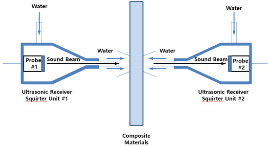
Figure 1.
Through-transmission ultrasonic method with squirter.
As shown in Figure 2, when ultrasound propagates into another medium, the sound pressure received by the opposite side varies depending on the impedance of the medium. If the magnitude of this sound pressure is represented on a 2D plane, it can be expressed with different contrasts, as shown on the right. When the obtained ultrasonic images are evaluated, intact and defective parts exhibit different sound pressures, making it possible to determine the presence of a defect.
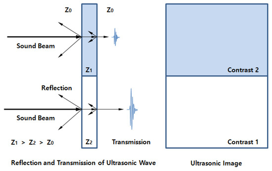
Figure 2.
Ultrasonic image of a material with different impedances.
Figure 3 shows the case of delamination, which is a defect that frequently occurs in composite materials. The delaminated part causes total reflection (100%) of ultrasound due to the air layer formed. The parts of the structure that receive ultrasound and those that do not (as a result of total reflection) clearly show differences in the transmitted sound pressure. Delamination can be detected by finding such differences in sound pressure in ultrasonic images.
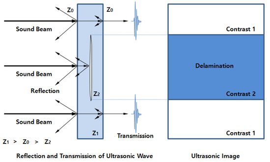
Figure 3.
Ultrasonic image obtained from a delamination layer.
A defect that frequently occurs in composite materials along with delamination is a void, as shown in Figure 4. Ultrasonic scattering occurs on the surface of a void, resulting in a difference in sound pressure between an intact part without a void and a defective part with a void. The defects can be detected using this difference in the sound pressure.
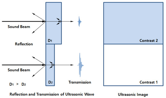
Figure 4.
Change in ultrasonic sound pressure due to a void.
The ultrasound sound pressure changes because of the acoustic impedance change and attenuation/scattering in a material. Defects are also detected through the ultrasonic sound pressure images obtained as a result of such changes.
The pre-developed multi-joint robotic ultrasonic inspection system performs inspections by arranging the transmitter and receiver sensors in a straight line. If their coordinates are misaligned due to deformation of the mechanism, a spurious sound pressure change occurs because the two sensors are no longer arranged in a straight line. In this case, the reliability of the inspection is degraded because the sound pressure change occurs even in an intact part that is not a defect. To address this problem, it is necessary to measure the degree of misalignment caused by the deformation of the mechanism and to correct the misalignment.
2.2. Collection and Arrangement of Coordinates for Improvement of Systems’ Accuracy
We addressed the problem of misinterpreting an intact part for a defect when the sound pressure changes due to the misalignment of the two sensors, which is caused by the deformation of the mechanism. Consequently, an algorithm was developed that is capable of measuring the degree of deformation by a stepwise procedure that involves using a 3D laser measuring instrument, calculating the correction values based on the measurements, and compensating for the axis misalignment. This algorithm first follows a motion along the bogie axis (yy-axis) after setting the coordinate system, as shown in Figure 5; it also measures the coordinate values of the x-, y-, and z-coordinates at the robot control point position to correct the coordinate misalignment of coordinates due to the deformation of the mechanism. In this instance, it is assumed that the control of the traveling multi-joint robot is accurate and that deformation occurs only in the bogie that moves the robot.
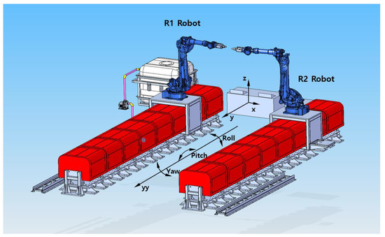
Figure 5.
Robot coordinate setting for collecting coordinate values.
To confirm the roll, pitch, and yaw using the measured spatial coordinates, the misalignment of the robot bogies in 3D space is calculated on all yy-axes using Equations (3)–(5), respectively.
As the actual multi-joint robot is controlled using the x-, y-, and z-coordinate values, the calculated roll, pitch, and yaw values are applied to the rotation matrices of Equations (6)–(8), respectively, to calculate the misaligned coordinate values on all the yy-axes.
Using the obtained coordinate values, the misaligned coordinate values can be accurately restored even when the position changes due to movement of the robot.
3. Experimental Setup and Method
In this study, we attempted to solve the deterioration in the accuracy and reliability of inspection, which is known to be caused by the deformation and misalignment of the bogie part. The misalignment occurs due to the usage environment of the pre-developed multi-joint robotic ultrasonic inspection system. To this end, a software algorithm capable of automatically compensating for the level values of the multi-joint robot was developed and applied to an actual system for verification. The ultrasonic system used for the analysis generated/received signals using a pulser/receiver; amplification and filter devices were installed in consideration of the attenuation of ultrasonic signals. To convert the received analog signal to digital, an analog–digital converter was installed and programmed.
First, to examine the axis misalignment of the system intuitively, the water columns of the two robots were accurately aligned with no product to be inspected, as shown in Figure 6. Data were acquired while the robots were moved by 100 mm in the z direction and by 650 mm in the y direction, in 3 mm intervals; the data were expressed as 2D images. The frequency of the ultrasonic sensor was set to 0.5 MHz. Regarding the ultrasonic sound pressure, the linear scale was set to 50% and the log scale to 80%.
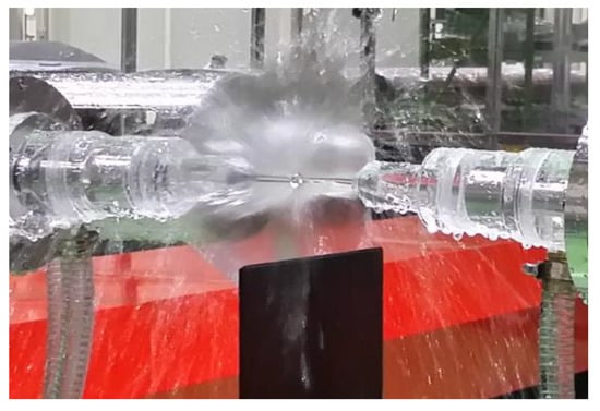
Figure 6.
Shape of the squirter.
After intuitively examining the axis alignment, the spatial coordinates were measured at the respective control points of the R1 robot (x-axis origin distance: 2393.058 mm; y-axis origin distance: 0.000 mm; z-axis origin distance: −250.535 mm) and the R2 robot (x-axis origin distance: 2104.081 mm; y-axis origin distance: 311,737.000 mm; z-axis origin distance: −250.554 mm); this was achieved by using a laser tracker (Absolute Tracker from Leica, Switzerland) to obtain the spatial coordinates of the bogie axis that was misaligned.
The roll, pitch, and yaw were calculated using the measured coordinate values and Equations (3)–(5). Subsequently, these roll, pitch, and yaw values were applied in the rotation matrices of Equations (6)–(8) with the objective of calculating the misaligned coordinate values on all the yy-axes. In the developed algorithm, correction values were derived by using these values, with the aim of performing movements while each axis was corrected.
To verify the performance of the algorithm, a reference specimen that simulated artificial defects was fabricated, as shown in Figure 7.
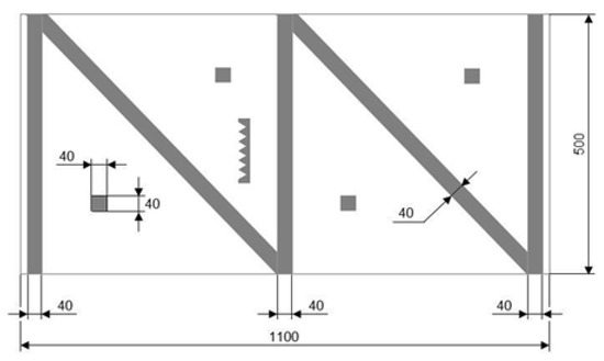
Figure 7.
Shape and dimension of reference specimen (mm).
The geometry and simulated defects of the specimen were fabricated in accordance with the Airbus standard. The specimen was scanned to acquire an image before compensating for the misalignment of the bogie axis, as shown in Figure 8. Another image was also acquired after performing the pitch and yaw corrections. The images were compared and analyzed. In addition, for a composite material specimen without defects, the images obtained before and after correction were compared and analyzed.
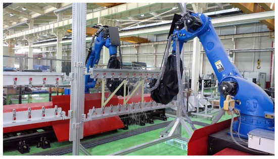
Figure 8.
Scanning for reference specimens with artificial defects.
4. Results
Figure 9 shows the ultrasonic image acquired in the absence of the specimen and the position coordinate values for three axes, which were measured using the laser tracker during transport of the bogie axis to identify axis misalignment. As shown in Figure 9, the ultrasonic image acquired during the transport of the bogie axis was observed to include dark and bright sections, which appear to have occurred because of the change in sound pressure caused by axis misalignment.
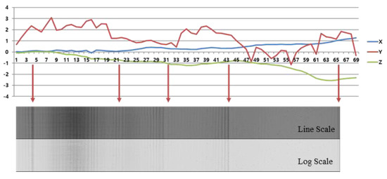
Figure 9.
Image of x-, y-, and z-axis misalignment for the R1 and R2 robots.
In the case of the y-axis, the intensity of the ultrasound sharply decreased at positions where there were rapid changes on the coordinate axis, resulting in the formation of dark images. The misalignment of the y-axis had the greatest effect on the ultrasonic image. The x-axis, which represents the distance between the robots, had a lower effect on the change in sound pressure.
To correct the axis misalignment, the roll, pitch, and yaw values were calculated at each point. This calculation was achieved by using the coordinate values that were measured using the laser tracker and Equations (3)–(5). Subsequently, these roll, pitch, and yaw values were applied in the rotation matrices to calculate the misaligned coordinate values on all yy-axes and the derived correction values. Based on this procedure, the developed software performed automatic correction during scanning.
Figure 10 shows the ultrasonic image that was acquired after performing yaw correction, in which the deleterious effects appearing in the ultrasonic image before correction are significantly diminished. Although the misalignment of the y-axis had the greatest effect among the three axes, pitch correction was also performed and data were re-acquired.
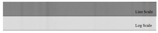
Figure 10.
Image after yaw correction.
Figure 11 shows the image acquired after performing pitch correction in addition to the yaw correction. The change in the sound pressure was observed to be constant at almost all points; this confirms that the developed algorithm can perform accurate axis compensations.
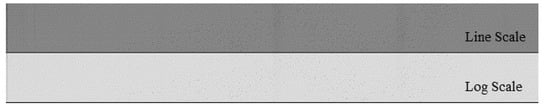
Figure 11.
Image after pitch and yaw correction.
Figure 12 shows C-scan images of the reference specimen that were captured before and after implementing the corrections; the specimen was fabricated to verify the validity of the correction algorithm. C-scan is a method of taking plane images using a signal measured by the TTU method. Here, only pitch and yaw corrections were performed, as in the previous case. As shown in Figure 12a, a relatively dark image appeared within the red box before correction because the received sound pressure was reduced by axis misalignment. This characteristic can be mistaken for delamination or the presence of voids during actual composite material inspection. To address this problem, axis misalignment was corrected by applying the developed algorithm, then an image was acquired from the same specimen. Figure 12b shows that the changes in contrast that appeared before the correction were almost completely removed. This confirmed that the developed algorithm could accurately correct the axis misalignment.
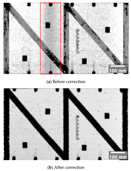
Figure 12.
C-scan images of the specimen with simulated defects.
The same experiment was performed with the actual composite material specimen; the results are shown in Figure 13. As with the results of the reference specimen, the majority of the changes in image contrast caused by axis misalignment were removed after correction.
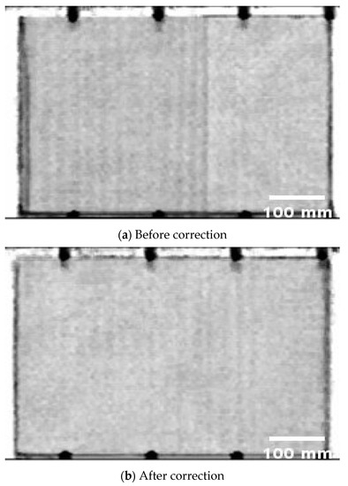
Figure 13.
Ultrasonic images of the actual composite material specimen.
5. Conclusions
In this study, an algorithm for correcting the deformation and misalignment of the bogie part was developed to solve the deterioration in the accuracy and reliability of inspection to ensure the integrity of composite material structures. The misalignment may occur due to the usage environment of the pre-developed multi-joint robotic ultrasonic inspection system. The performance of the algorithm was verified by fabricating a reference specimen. We observed that the contrast on the ultrasonic image changed even when there was no defect because axis misalignment changed the ultrasound beam’s intensity. Therefore, the correction algorithm was used to address this problem and we confirmed that changes in contrast caused by axis misalignment could be corrected; however, the variations in contrast that were caused by defects could not be corrected. These results imply that deterioration in the inspection reliability that is caused by axis misalignment can be solved.
Author Contributions
Writing-original draft, J.S.L.; writing-review and editing, T.S.P., Y.M.C. and I.K.P.; supervision, I.K.P. All authors have read and agreed to the published version of the manuscript.
Funding
This research was supported by the Research Program funded by the SeoulTech (Seoul National University of Science and Technology), grant number 2020-0514.
Conflicts of Interest
The authors declare no conflict of interest.
References
- Park, H.S.; Choi, M.Y.; Park, J.H.; Kim, W.J.; Choi, W.J. Study on the qualitative defects detection in composites by optical infrared thermography. J. Korean Soc. Nondestruct. Test. 2011, 31, 150–156. [Google Scholar]
- Towsyfyan, H.; Biguri, A.; Boardman, R.; Blumensath, T. Successes and challenges in non-destructive testing of aircraft composite structures. Chin. J. Aeronaut. 2019, 33, 771–791. [Google Scholar] [CrossRef]
- Choi, H.S.; Cho, Y. Structural health monitoring techniques for composite aircraft. J. Korean Soc. Nondestruct. Test. 2010, 30, 54–59. [Google Scholar]
- Su, F.; Zheng, L.; Sun, F.; Wang, Z.; Deng, Z.; Qiu, X. Novel drill bit based on the step-control scheme for reducing the CFRP delamination. J. Mater. Process. Technol. 2018, 262, 157–167. [Google Scholar] [CrossRef]
- Ghobadi, A. Common type of damages in composites and their inspections. World J. Mech. 2017, 7, 24–33. [Google Scholar] [CrossRef]
- Gholizadeh, S. A review of non-destructive testing methods of composite materials. Procedia Struct. Integr. 2016, 1, 50–57. [Google Scholar] [CrossRef]
- Polimeno, U.; Meo, M.; Almond, D.P.; Angioni, S.L. Detecting low velocity impact damage in composite plate using nonlinear acoustic/ultrasound methods. J. Compos. Mater. 2010, 17, 481–488. [Google Scholar] [CrossRef]
- Taheri, H.; Hassen, A.A. Nondestructive ultrasonic inspection of composite materials: A comparative advantage of phased array ultrasonic. Appl. Sci. 2019, 9, 1628. [Google Scholar] [CrossRef]
- Lim, H.M.; Lee, B.Y.; Kim, Y.K. Barely visible impact damage detection analysis of CFRP by various NDE techniques. Compos. Res. 2013, 26, 195–200. [Google Scholar] [CrossRef][Green Version]
- Lu, Z.; Xu, C.; Pan, Q.; Xiao, D.; Meng, F.; Hao, J. Kinematic constraint analysis in a twin-robot system for curved-surface nondestructive testing. Ind. Robot Int. J. 2016, 43, 172–180. [Google Scholar] [CrossRef]
- Jennifer, M.E.; Thomas, E.M.; Staffan, J. Ultrasonic methods for detection of micro porosity in composite materials. Rev. Prog. Quant. Nondestruct. Eval. 1993, 12, 1281–1287. [Google Scholar]
- Lim, J.S.; Park, T.S.; Ha, S.J.; Park, I.K. Development of a multi-joint robotic ultrasonic inspection system to secure the integrity of composite structures. J. Korean Soc. Nondestruct. Test. 2018, 38, 120–125. [Google Scholar] [CrossRef]


© 2020 by the authors. Licensee MDPI, Basel, Switzerland. This article is an open access article distributed under the terms and conditions of the Creative Commons Attribution (CC BY) license (http://creativecommons.org/licenses/by/4.0/).