Article

Deflection Sliding Mode Control of a Flexible Bar Using a Shape Memory Alloy Actuator with an Uncertainty Model

by
Najmeh Keshtkar
1,*,
Sajjad Keshtkar
2,* and
Alexander Poznyak
1
1
Department of Automatic Control, CINVESTAV del IPN, Mexico City 07360, Mexico
2
School of Engineering and Science, Tecnologico de Monterrey, Tampico 89600, Mexico
*
Authors to whom correspondence should be addressed.
Appl. Sci. 2020, 10(2), 471; https://doi.org/10.3390/app10020471
Submission received: 4 December 2019 / Revised: 20 December 2019 / Accepted: 26 December 2019 / Published: 9 January 2020

Abstract

:
This paper presents a penalty-based sliding mode control (SMC) law for flexible bar system, which uses shape memory alloy (SMA) as actuator. SMA actuators are lightweight, compact and flexible which facilitate their integration into flexible structures. The proposed control law manipulates SMA current to exert the necessary force for deflecting the flexible bar into the desired state. Numerical simulations demonstrate that this new method can control the one-input, multi-output under-actuated system of the flexible bar efficiently. The mathematical model of the flexible system is obtained using physical discretization. The bar is modeled as a combination of rigid rods connected by joints without elasticity and friction. This model demonstrates the flexibility of the system in an effective way. The numerical simulation illustrates the feasibility of the proposed model for analyzing the oscillations of the system and the effectivness of proposed control algorithms.

1. Introduction

Flexible bars establish an important role in many engineering applications such as space tethers, catheters, robotic links, cantilever cranes, astronomical telescopes, etc. [1,2,3,4]. They are widely used in industries due to their higher speed operation and lower energy consumption as a result of their lower overall mass. Moreover, light-weight links require smaller actuators which are beneficial for cost reduction of space robot transportation. Hence, flexible bars are superior to rigid ones in the above respects. However, it is well known that these systems could give rise to oscillations which make it difficult to obtain a precise tracking response [5]. Additionally, the mathematical model of the system becomes more complicated because of the flexibility. These are the two major challenges for the usage of flexible bars. Therefore, many works have been aimed at dynamic modeling and control of such systems and coursed into new channels to design controlled structures with high-performance characteristics.
The dynamic modeling of the flexible bar is essential for understanding the system behavior and consequently designing the controller. One way to describe the mathematical model of these systems is through discretization. The discretization approach can be realized either mathematically or physically [6]. In the mathematical discretization, the finite difference method, as well as the Ritz–Galerkin procedure, can be applied. Although this is an efficient method, it becomes inconvenient for more than a few modes and can lead to numerical difficulties for high numbers of modes [7]. On the other hand, physical discretization models the system as finite elements or point mass elements. This method has been frequently adopted for describing different physical systems like rope [8,9], chain [10], whip [11], space tethers [12], and has provided reasonably accurate results.
The stringent behavior requirements imposed on flexible structures, on the other hand, demands precise control of these structures. In order to control the system efficiently both the controller and the actuator should be selected carefully. As for the actuator, smart materials such as shape memory alloys (SMA), have been frequently adopted in controllable structures including flexible bars [12]. SMAs are able to return to a predefined shape upon the supply of heat. The significant advantages of SMA wires in comparison to other smart materials such as piezoelectrics are the large displacement, complete recovery deformation, and high stiffness [13]. Furthermore, SMA can be heated easily by passing an electrical current through it [14]. This makes the shape control of structures integrated with SMA actuators more feasible.
During the heating and cooling process, a phase transformation occurs in the crystalline structure of the SMA. This phenomenon introduces a hysteresis effect, which is highly nonlinear. Due to the hysteresis, the control of flexible structures actuated by shape memory alloys has turned to a challenging task [15]. Various linear control approaches including proportional-integral (PI) [16] and proportional-integral-derivative (PID) [17,18] as well as nonlinear optimal and fuzzy logic controls [19], and variable structure/sliding mode control has been applied on SMA actuated devices. Among these methods, the sliding mode algorithms have shown promising results thanks to their less sensitivity to system parameter variations and noise disturbances [20,21,22]. The sliding-mode control (SMC), is a nonlinear feedback control whose structure is intentionally changed to achieve the desired performance. However, this change of structure gives rise to an undesirable phenomenon of oscillations having finite frequency and amplitude, which is known as chattering. Although some important general results for controlling flexible structures have been obtained using these controllers, most of these methods are application-specific and/or lack rigorous stability proof.
The present study proposes a sliding mode control design based on the penalty approach and actuated by shape memory alloys to stabilize a flexible bar system in the presence of uncertainties. The control law is based on the system model which includes the one-input multi-output equation of motion of the flexible bar and the mathematical model of the shape memory alloy. The equation of motion of the system is obtained using a physical discretization approach. Moreover, the SMA actuation is described using Choi model [23], based on the step-input response of the SMA actuator. Although other models have been proposed to describe the dynamic behavior of shape memory alloys [24,25,26], Choi model is selected due to the description of the force-current relationship of the SMA actuator in a straightforward way which is computationally efficient (The shape recovery of SMA happens under temperature control and highly depend on potential alloys materials (such as NiTi, Cu-based and some others), as well on compositions, transformation temperatures (depending on the composition), ambient temperatures and so on. Obviously, the considered controlled model depends on the variations of the parameter at the heating and cooling stages. These changes of variation are considered here as uncertainty which can be suppressed using sliding mode approach.).
In summarize, the novelty of this work, compared to previous literature, consists in two points: the complete knowledge of the parameters of the considered model (especially the parameters of the shape memory alloy) is not required as the sliding mode control (SMC) is applied to overcome this trouble; the state variables in the desired regime are connected by a set of algebraic constrains, which make it impossible to apply direct application of SMC; therefore a special Lyapunov-like function, including the penalty term, is introduced to realize the desired dynamics.

2. System Description and Equations of Motion

2.1. Model Description

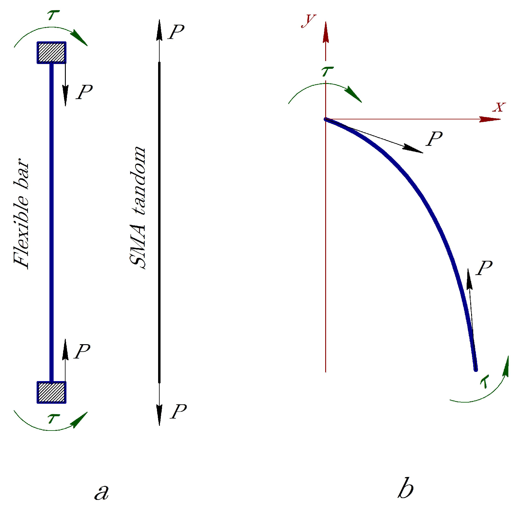
The mechanical model under consideration consists of a flexible bar actuated by an SMA wire as it is shown in Figure 1. The SMA tendon is offset from the neutral axis of the rod by a fixed distance of a. According to Figure 1, SMA wire connects the beginning and end of each section of length b of the entire beam length B. Electric current i is the same throughout the wire and in every section of it. This electric current produces the same amount of force in each section of wire. The shape memory alloy wire is stretched in the austenitic state, cooled through the temperature range of the start and finish of the forward phase transition, and in the achieved martensitic state, the tensile load is removed. After that, the wire is embedded in the construction as described above. As the current is transmitted through the wire, it heats up, a reverse phase transition occurs, the phase deformations induced by the stretching of the wire disappear, its length is reduced and it generates forces that create a moment on the bar, causing it to bend to an angle α , Figure 2. By controlling the current, the deflection of the flexible bar becomes controllable.

2.2. Equations of Motion

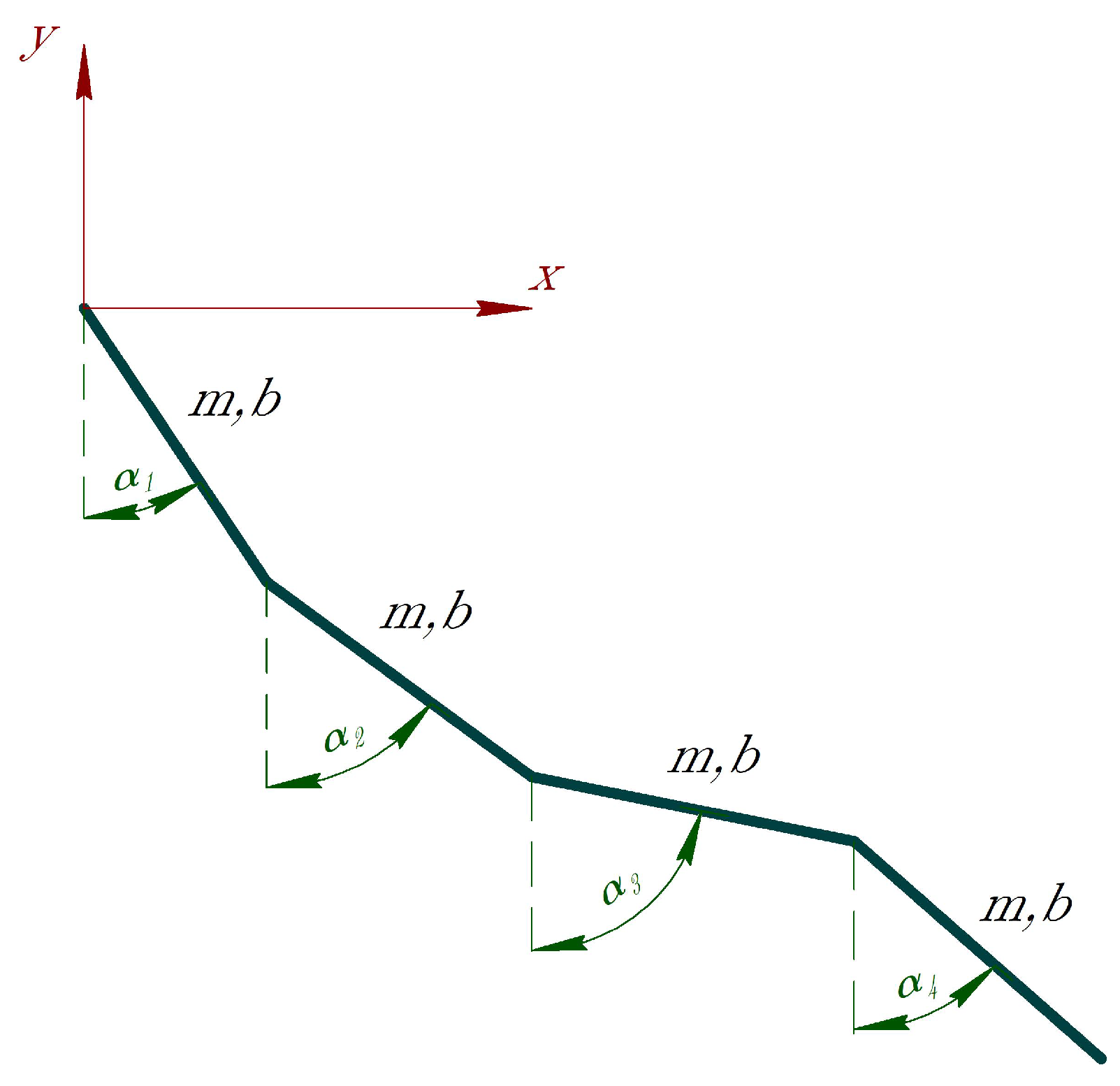
Consider a flexible bar of mass M and length B consisting of n cylindrical rods with masses m i = m = M / n and lengths b i = b = B / n , i = 1 , . . . , n , in a gravitational field and assume that the system is constrained to move only in the two-dimensional plane. Figure 3 shows the geometric representation of this model.
In order to introduce the equations of motion, the generalized coordinates must be specified; the coordinates must uniquely determine the state of the system. In this model, angular coordinates α i which indicates the inclination of the consecutive segments toward the y-axis are chosen as generalized coordinates. The position of the i-th segment center of mass ( x i , y i ) can be represented as:
x i = j = 1 i 1 b sin ( α j ) + 1 2 b sin α i y i = j = 1 i 1 b cos ( α j ) 1 2 b cos α i
where α i indicates the angle between the ith rod and the vertical axis y, b is the length and m represents the mass of each rod.
To obtain the mathematical model of the system the Lagrangian function and Lagrange’s equation can be used. The Lagrangian function is defined by
L = T U ,
where T is the kinetic energy and U is the potential energy of the system. The Lagrange’s equation is described as follows
d d t q ˙ j L q j L = Q n o p o t
where q j and Q n o p o t represent the j-th generalized coordinate and non-potential force respectively. In our case
q 1 = α 1 , q 2 = α 2 , . . . , q n = α n .
The kinetic energy of the model is the sum of kinetic energy of each rod and is given by
T = 1 2 i = 1 n m x ˙ i 2 + y ˙ i 2 + I i α ˙ i 2 = m b 2 i = 1 n 3 n i + 1 6 α ˙ i 2 + m b 2 i = 1 n j = i + 1 n 2 n j + 1 2 α ˙ i α ˙ j cos α i α j ,
where I i = ( 1 / 12 ) m b 2 is the moment of inertia of each segment about its mass center. In the same way, the potential energy of the system depends on the gravitational energy of each segment and is expressed as follows
U = i = 1 n m g y i = i = 1 n 2 n i + 1 2 m g b cos ( α i ) ,
where g indicates the gravitational acceleration.
Introduce the vector α = [ α 1 , . . . , α n ] for the considered system. After applying the Lagrange equation, the general form of the equation of the motion of the system can be expressed as:
A ( α ) α ¨ + B ( α , α ˙ ) α ˙ + C ( α ) = Q n o p o t
where:
A ( α ) = A 11 A 12 A 1 n A 12 A 22 A 2 n A 1 n A 2 n A n n
and
A i j = 3 ( n j ) + 1 3 m b 2 when i = j A i j = 2 ( n j + 1 ) 1 2 m b 2 cos ( α i α j ) when i j .
The matrix B is skew-symmetric and is expressed by
B ( α , α ˙ ) = 0 B 12 B 1 n B 12 0 B 2 n B 1 n B 2 n 0
with
B i j = 2 ( n j + 1 ) 1 2 m b 2 q ˙ j sin ( α i α j )
and the vector C is described as
C ( α ) = C 1 C 2 C n
where
C i = ( n i ) + 1 2 m g b sin α i .

2.3. Study of the Behavior of the System

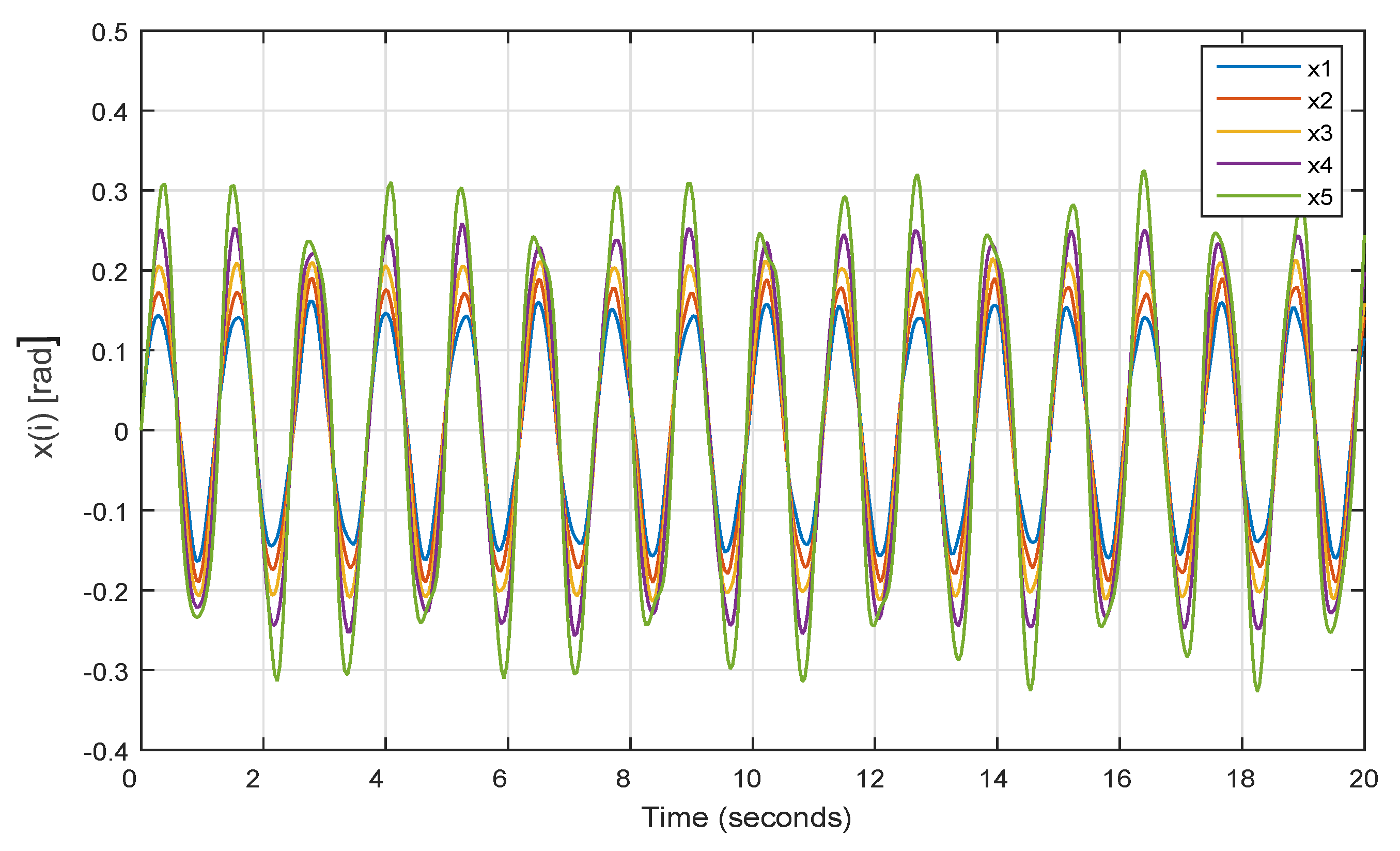
The mathematical model of the system is verified using numerical simulation. The model used in the simulation consists of 5 segments of 0.01 m length and 0.001 kg mass. There are no external forces acting on the system ( Q n o p o t = 0 ) and the initial conditions are α 1 = α 2 = . . . = α n = 0 rad and α ˙ 1 = α ˙ 2 = . . . = α ˙ n = 0.1 rad/s.
As can be seen from the simulation results in Figure 4, the solution of nonlinear equations contains oscillations. The oscillations in the system occur in the form of beats, in which energy is cyclically transferred from one rod to the other.

3. Sliding Mode Control of the Flexible Bar Using Penalization Method

The control objective is to design a single input τ which simultaneously controls all the states and provides the desired performance. The input torque τ is produced by an SMA actuator and has the same magnitude in all sections of the flexible bar as shown in Figure 2. The SMA actuator employed in this work produces actuating torque in a compressive manner by applying electrical current. Therefore, the input torque τ of the flexible bar system will be designed first and, afterwards, based on the torque-current equation of SMA actuator, the electrical current input i of the actuator will be obtained.

3.1. Sliding Mode Controller Design and Lyapunov-Like Stability Analysis

In order to stabilize the flexible bar system for the current system, a new method based on sliding mode techniques via a penalty approach is proposed. The main reason for the election of this control strategy is the insensitivity of this algorithm to the shape memory alloy parameter variations during the heating and cooling stages.
The equation of motion of the system Equation (6) can be rewritten as
x ¨ = A 1 B x ˙ A 1 C + A 1 D τ ,
where
x 1 = α 1 , x 2 = α 2 , . . . , x n = α n
and D τ = Q n o p o t = [ 1 , 1 , , 1 ] τ .
Note that when the flexible bar reaches its desired state, it will be in an equilibrium position as x ¨ = x ˙ = 0 . Therefore, the following relation holds for the system in the equilibrium position
C = ( ( n 1 ) + 1 2 ) m g l sin ( x 1 ) ( ( n 2 ) + 1 2 ) m g l sin ( x 2 ) ( ( n 3 ) + 1 2 ) m g l sin ( x 3 ) 1 2 m g l sin ( x n ) = D τ
which makes a constraint between the angular position of segments and the control input. Dividing the first component of Equation (8) by its following components gives the relation between the angles at equilibrium point as follows:
C 1 C 2 n 1 + 1 2 m g l sin ( x 1 ) n 2 + 1 2 m g l sin ( x 2 ) = 1 n 1 + 1 2 n 2 + 1 2 sin ( x 1 ) sin ( x 2 ) = 0 C 1 C 3 n 1 + 1 2 m g l sin ( x 1 ) n 3 + 1 2 m g l sin ( x 3 ) = 1 n 1 + 1 2 n 3 + 1 2 sin ( x 1 ) sin ( x 3 ) = 0 C 1 C n n 1 + 1 2 m g l sin ( x 1 ) 1 2 m g l sin ( x n ) = 1 2 ( ( n 1 ) + 1 2 ) sin ( x 1 ) sin ( x n ) = 0
thus, the vector of constraints can be defined by
g = g 1 g 2 g n 1 = ( ( n 1 ) + 1 2 ) ( ( n 2 ) + 1 2 ) sin ( x 1 ) sin ( x 2 ) ( ( n 1 ) + 1 2 ) ( ( n 3 ) + 1 2 ) sin ( x 1 ) sin ( x 3 ) 2 ( ( n 1 ) + 1 2 ) sin ( x 1 ) sin ( x n )
in which g = 0 . The obtained constraints will be used later on in the design of the SMC.
On the other hand, the tracking error for the desired constant angular position x i * ( t ) is described as
e i ( t ) = x i ( t ) x i * ( t ) ,
by using the equation of tracking error and its derivative, a first order sliding variable can be designed as
S = e ˙ 1 + c 1 e 1 e ˙ 2 + c 2 e 2 e ˙ n + c n e n ,
where e i = x i x i * , i = 1 , 2 , , n and c 1 , c 2 , . . . , c n are positive constants. The derivative of the sliding surface can be taken as follows
S ˙ = e ¨ 1 + c 1 e ˙ 1 e ¨ 2 + c 2 e ˙ 2 e ¨ n + c n e ˙ n = x ¨ 1 + c 1 x ˙ 1 x ¨ 2 + c 2 x ˙ 2 x ¨ n + c n x ˙ n = x ¨ + C 0 x ˙
where
C 0 = c 1 0 0 0 c 2 0 0 0 c n > 0 .
In the next step, a switching control law will be obtained according to the Lyapunov stability theorem. First, the Lyapunov function V is introduced as
V : = S T S + μ 2 g 2 , μ > 0 ,
where g is the penalty function due to the mentioned constraints of the system. The suggested Lyapunov function contains two terms, the first one is traditional and is responsible for the attainment of the sliding surface S = 0 , the second term corresponds to the penalty which we introduced to guarantee fulfilling the constraints g ( x ) = 0 . and by taking f = A 1 B C 0 x ˙ A 1 C and d = A 1 D , the equation reduces to
V ˙ = 2 S T ( f + τ d ) + μ g ( x ) d d x g ( x ) x ˙ 2 S f + 2 τ S d + μ g ( x ) d d x g ( x ) x ˙
by considering the control input as τ = τ 0 + τ c o m p , the following relation can be obtained
V ˙ 2 S f + 2 ( τ 0 + τ c o m p ) S d + μ g ( x ) d d x g ( x ) x ˙ = 2 S f + + 2 τ 0 S d + μ g ( x ) d d x g ( x ) x ˙ + 2 τ c o m p S d
where f + < is the upper bound of f . In the conventional situation (when we deal with the control problem with additional constrains) we may take the parameter μ in Equation (13) equal to zero and the separation of the control action τ in two terms τ 0 and τ c o m p (compensating) is not required. In our case (the constrained control designing) the time derivative of the suggest Lyapunov function obligatory contains the term which has no (as a multiplier) value of s , and can not be included into the discontinues control law. So, the specifics of the considered problem, dealing with the additional state constrains, require to introduce an additional compensating control to provide a finite time convergence of the closed-loop system to the desired Sliding surface keeping these constrains in force.
The control input τ 0 can be selected as
τ 0 = k S d Sign S d 2 sign ( S d ) sign ( d Sign S ) k S = k 0 d 2 S S d d Sign S + ε 0 , ε 0 1
where Sign S = ( sign S 1 , sign S 2 , . . . , sign S n ) . Consequently,
V ˙ 2 S f + + 2 S d τ 0 + μ g ( x ) d d x g ( x ) x ˙ + 2 d S τ c o m p = 2 S f + 2 k S S d d Sign S d 2 sign ( S d ) sign ( d Sign S ) + μ g ( x ) d d x g ( x ) x ˙ + 2 d S τ c o m p = 2 S f + 2 k S d 2 S d d Sign S + μ g ( x ) d d x g ( x ) x ˙ + 2 d S τ c o m p .
Therefore,
V ˙ 2 S f + 2 k 0 S S d d Sign S S d d Sign S + ε 0 + μ g ( x ) d d x g ( x ) x ˙ + 2 d S τ c o m p = 2 S f + 2 k 0 S 1 ε 0 S d d Sign S + ε 0 + μ g ( x ) d d x g ( x ) x ˙ + 2 d S τ c o m p
which provides
V ˙ 2 S f + k 0 + 2 k 0 ε 0 S S d d Sign S + ε 0 + μ g ( x ) d d x g ( x ) x ˙ + 2 S d τ c o m p = 2 S + μ 2 g f + k 0 2 μ 2 g f + k 0 + 2 k 0 ε 0 S S d d Sign S + ε 0 + μ g ( x ) d d x g ( x ) x ˙ + 2 S d τ c o m p
Finally, τ c o m p can be chosen to satisfy the following equation
2 μ 2 g f + k 0 + 2 k 0 ε 0 S S d d Sign S + ε 0 + μ g ( x ) d d x g ( x ) x ˙ + 2 S d τ c o m p = 0
which implies
τ c o m p = 2 μ 2 g f + k 0 2 S d 2 k 0 ε 0 S S d d Sign S + ε 0 + μ g ( x ) d d x g ( x ) x ˙ 2 S d
Now, it can be shown that V reaches zero in a finite time. For k 0 = f + + 1 2 ρ and ρ < 0
V ˙ ρ S + μ 2 g
since
S + μ 2 g V
it follows
V ˙ ρ V .
which implies
V 1 2 ρ t + V ( 0 )
therefore, V ( t ) = 0 for all t t r with
t r = 2 V ( 0 ) ρ .
As was mentioned before, the external torque τ is produced by the SMA actuator and the control input of the actuator is the electrical current i. In order to obtain the input current, the relation between the produced torque τ and the electrical current input i in the SMA actuator is used [23]:
ϕ d d t τ a + τ a = i ( t ) , a = c o n s t > 0 ,
where ϕ is the time constant of the actuator, i ( t ) is the current input and a is SMA tendon offset from the neutral axis of the bar. The Equation (25) is a low pass filter, thus
i ( t ) = i 0 ( t ) + i c o m p ( t )
where
i 0 ( t ) = τ 0 a i c o m p ( t ) = τ c o m p a
Consequently, it can be demonstrated that the external torque τ will track the current input i in a finite time. The dynamic equation of SMA can be written as
τ ˙ = 1 ϕ ( τ a i ( t ) ) .
Let us define
S A = τ a i
and introduce the following Lyapunov function:
V A = 1 2 S A S A
then by taking derivative of V A the following relation holds
V ˙ A = S A ( τ ˙ a d d t i ) = S A ( 1 ϕ ( τ a i ( t ) ) a d d t i ) = S A ( 1 ϕ S A a d d t i ) 1 ϕ S A 2 + a S A d d t i
if
d d t i h +
then
V ˙ A 1 ϕ S A 2 + a S A h + = 1 ϕ S A S A a h +
for S A a h + we have V ˙ A < 0 implying
S A S A : S A a h +
which demonstrates that the torque will track the current input.

3.2. Numerical Simulation

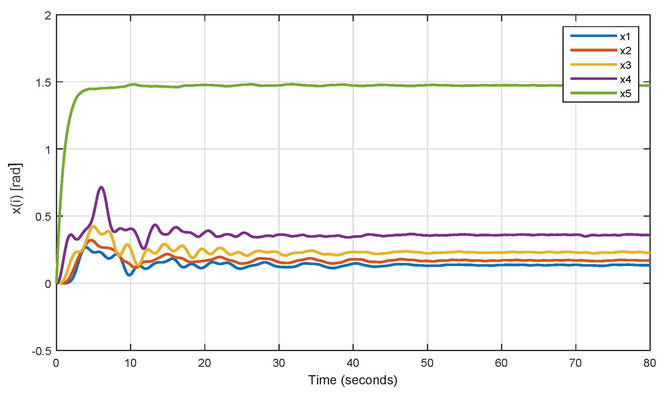
To demonstrate the performance of the proposed sliding mode control, numerical simulation is implemented using MATLAB-SIMULINK software. The parameters of the system and the initial conditions are the same as the previous numerical simulation of Section 2.1. According to [23] the time constant of the actuator has been taken as ϕ = 1.25 s. The distance a between the SMA tendon and the bar is 2 cm. The control objective is to drive the initial state of the flexible bar into the desired state. The desired angular position for the first variable is x 1 * = 0.2.
The simulation result is shown in Figure 5 and demonstrates that the proposed sliding mode control is able to stabilize the states of the system using SMA actuator. As one can see, all the states reach their desire values after around 50 s.
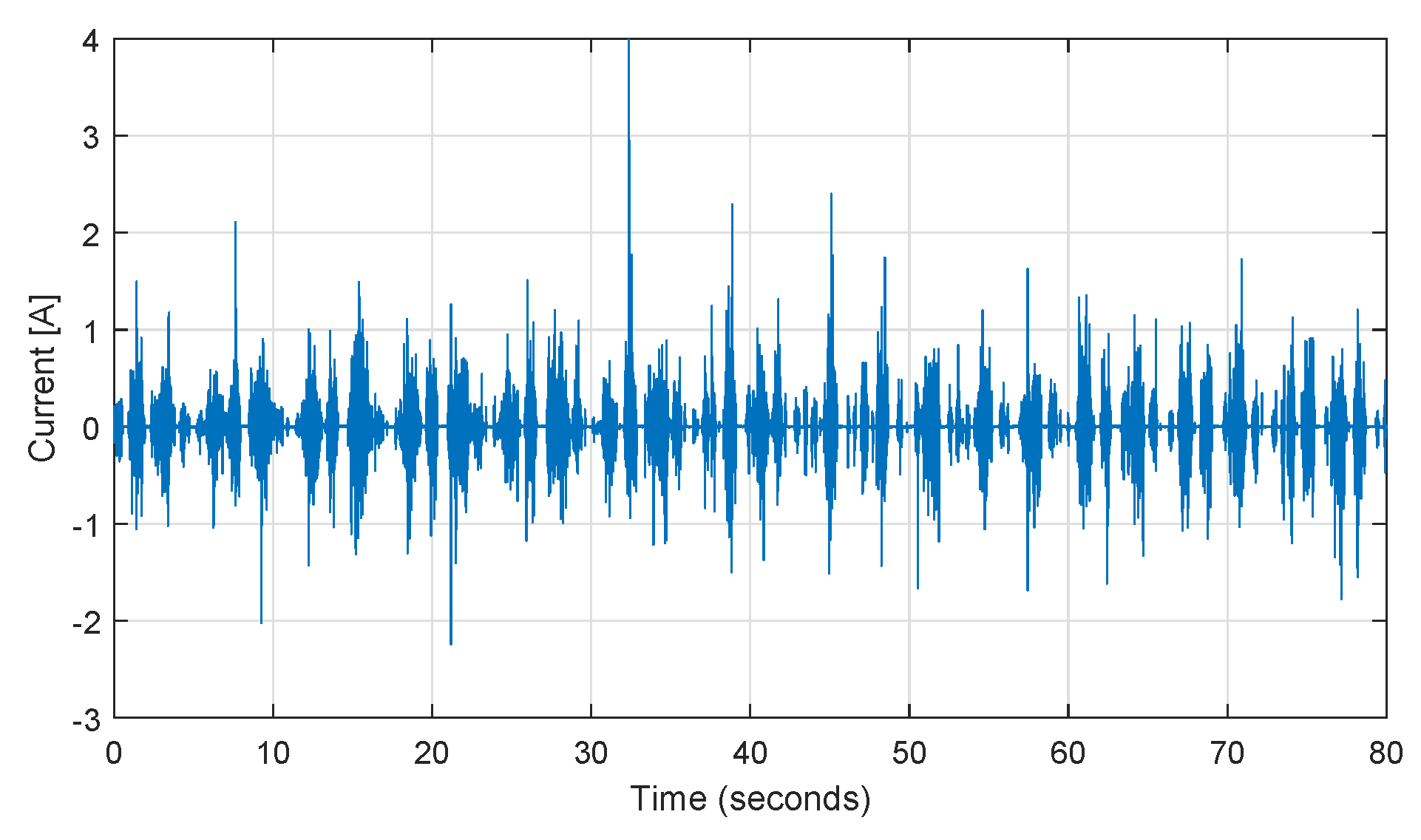
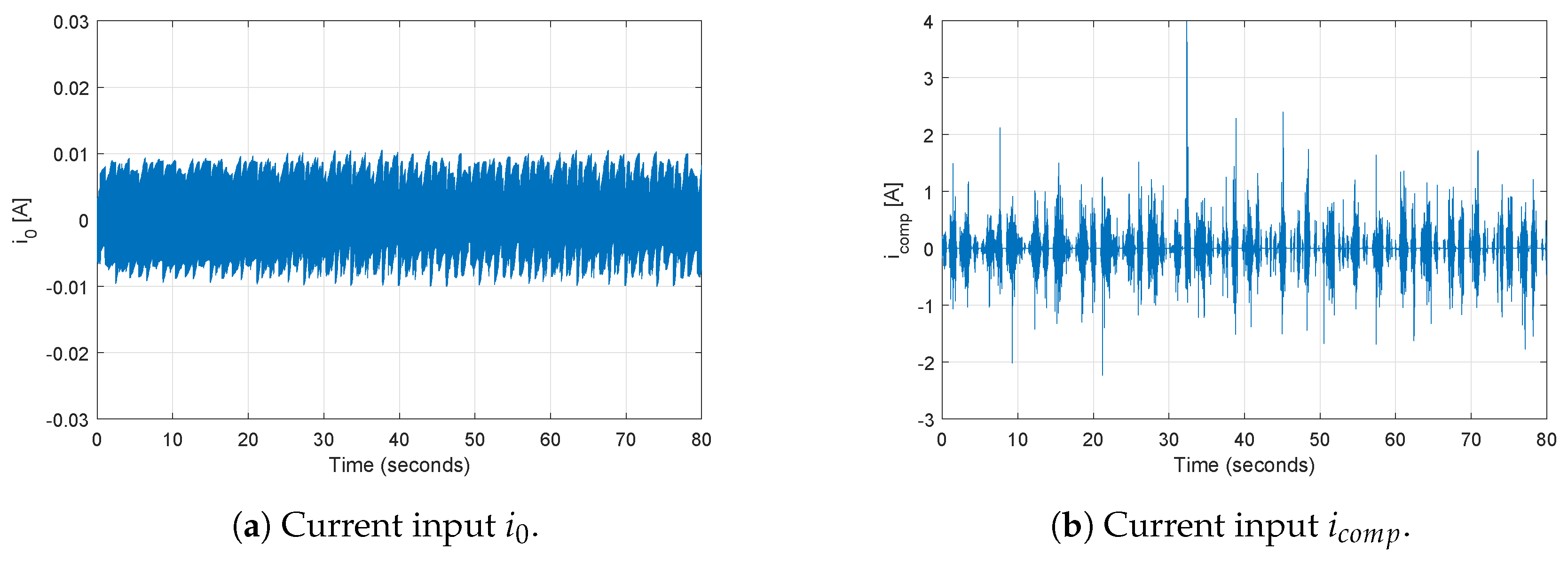
The control input i that drives the state variables of the system to the sliding surface is showed in Figure 6. As it was explained before, the current input is made of two components, i 0 and i c o m p . The signal of these two components is illustrated in Figure 7.
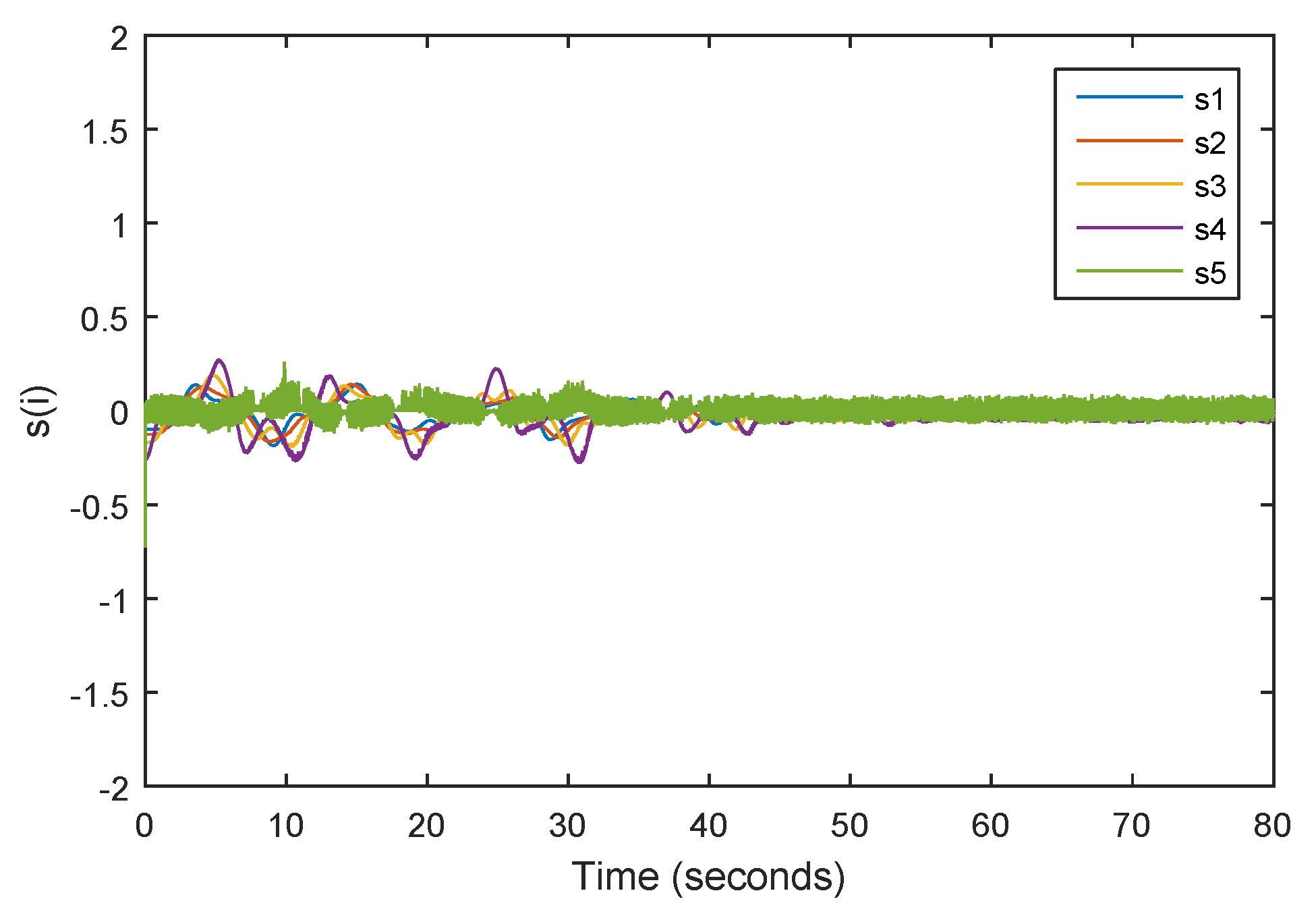
Figure 8 illustrates the finite-time convergence of the sliding variable to zero. This demonstrates that the states of the system are driven towards the sliding surface and remains on it thereafter.

4. Conclusions

The main contribution of the paper consists of designing the control mechanism for a flexible bar using shape memory alloy as an actuator when the mathematical model of the complete system (based on the corresponding physical processes) is a priori uncertain, namely, partially unknown. We presented here the theoretical analysis of the suggested method which is robust with respect to the presented uncertainties. A sliding mode control method is proposed for position control of a flexible bar actuated by SMA wire. The SMC design is based on the penalty approach and regulate the force exerted by the actuator on the flexible bar. The geometry constraints of the system in the equilibrium point are considered in designing the controller. The simulation results prove the high performance and effectiveness of the controller in stabilizing the system in a desired angular position. Furthermore, in order to take into account the flexibility of the system, physical discretization is applied for modeling the bar. As demonstrated in the illustrating numerical example, this approach provides a good insight into the dynamical behavior of the system.

Author Contributions

N.K. and A.P. conceived the contribution; N.K. and S.K. performed the numerical simulations; N.K. and A.P. analyzed the data; N.K. and S.K wrote the paper. All authors have read and agreed to the published version of the manuscript.

Funding

The authors would like to acknowledge the financial support of Tecnologico de Monterrey and CONACYT in the production of this work.

Acknowledgments

The authors thank the grant of SEP-Conacyt No. 251552 for the financial support of the activities related to the topic of this paper.

Conflicts of Interest

The authors declare no conflict of interest.

References

  1. Yu, B.; Jin, D.; Wen, H. Analytical deployment control law for a flexible tethered satellite system. Aerosp. Sci. Technol. 2017, 66, 294–303. [Google Scholar] [CrossRef]
  2. Khoshnam, M.; Skanes, A.C.; Patel, R.V. Modeling and estimation of tip contact force for steerable ablation catheters. IEEE Trans. Biomed. Eng. 2015, 62, 1404–1415. [Google Scholar] [CrossRef] [PubMed]
  3. Li, Z.; Du, R.; Yu, H.; Ren, H. Statics modeling of an underactuated wire-driven flexible robotic arm. In Proceedings of the 5th IEEE RAS/EMBS International Conference on Biomedical Robotics and Biomechatronics, São Paulo, Brazil, 12–15 August 2014; pp. 326–331. [Google Scholar]
  4. Lokman, A.H.; Soh, P.J.; Azemi, S.N.; Lago, H.; Podilchak, S.K.; Chalermwisutkul, S.; Jamlos, M.F.; Al-Hadi, A.A.; Akkaraekthalin, P.; Gao, S. A review of antennas for picosatellite applications. Int. J. Antennas Propag. 2017, 2017. [Google Scholar] [CrossRef]
  5. Benvenuto, R.; Salvi, S.; Lavagna, M. Dynamics analysis and GNC design of flexible systems for space debris active removal. Acta Astronaut. 2015, 110, 247–265. [Google Scholar] [CrossRef]
  6. Tyc, G. Dynamics and Stability of Spinning Flexible Space Tether Systems; Wendy Prystenski (Fort Garry Campus): Winnipeg, MB, Canada, 1998. [Google Scholar]
  7. Misra, A.; Xu, D.; Modi, V. On vibrations of orbiting tethers. Acta Astronaut. 1986, 13, 587–597. [Google Scholar] [CrossRef]
  8. Fritzkowski, P.; Kaminski, H. Dynamics of a rope as a rigid multibody system. J. Mech. Mater. Struct. 2008, 3, 1059–1075. [Google Scholar] [CrossRef] [Green Version]
  9. Kaminski, H.; Fritzkowski, P. Application of the rigid finite element method to modelling ropes. Latin Am. J. Solids Struct. 2013, 10, 91–99. [Google Scholar] [CrossRef]
  10. Tomaszewski, W.; Pieranski, P. Dynamics of ropes and chains: I. the fall of the folded chain. New J. Phys. 2005, 7, 45. [Google Scholar] [CrossRef] [Green Version]
  11. Bhat, D.N.; Kearney, J.K. On Animating Whip-type Motions. J. Vis. Comput. Animat. 1996, 7, 229–249. [Google Scholar] [CrossRef]
  12. Sohn, J.; Han, Y.; Choi, S.; Lee, Y.; Han, M. Vibration and position tracking control of a flexible beam using SMA wire actuators. J. Vib. Control. 2009, 15, 263–281. [Google Scholar] [CrossRef]
  13. Keshtkar, N.; Rivo, M.S.; Poznyak, A.; Keshtkar, S. Modeling and Simulation of Flexible Tethered Satellite System. In Proceedings of the 2018 15th International Conference on Electrical Engineering, Computing Science and Automatic Control (CCE), Mexico City, Mexico, 5–7 September 2018; pp. 1–4. [Google Scholar]
  14. Huang, W. Shape Memory Alloys and Their Application to Actuators for Deployable Structures; University of Cambridge: Cambridge, UK, 1998. [Google Scholar]
  15. Hannen, J.C.; Crews, J.H.; Buckner, G.D. Indirect intelligent sliding mode control of a shape memory alloy actuated flexible beam using hysteretic recurrent neural networks. Smart Mater. Struct. 2012, 21, 085015. [Google Scholar] [CrossRef] [PubMed] [Green Version]
  16. Grigorie, T.; Popov, A.; Botez, R.; Mamou, M.; Mebarki, Y. On–off and proportional–integral controller for a morphing wing. Part 1: Actuation mechanism and control design. Proc. Inst. Mech. Eng. Part G J. Aerosp. Eng. 2012, 226, 131–145. [Google Scholar] [CrossRef]
  17. Roshan, T.; Basnayake, B.; Amarasinghe, Y.; Wijethunge, D.; Nanayakkara, N.D. Development of a PID Based Closed Loop Controller for Shape Memory Alloy Actuators. In Proceedings of the 2018 Moratuwa Engineering Research Conference (MERCon), Moratuwa, Sri Lanka, 30 May–1 June 2018; pp. 460–464. [Google Scholar]
  18. Lynch, B.; Jiang, X.X.; Ellery, A.; Nitzsche, F. Characterization, modeling, and control of Ni-Ti shape memory alloy based on electrical resistance feedback. J. Intell. Mater. Syst. Struct. 2016, 27, 2489–2507. [Google Scholar] [CrossRef]
  19. Hadi, A.; Akbari, H.; Alipour, K.; Tarvirdizadeh, B. Precise position control of shape memory alloy-actuated continuum modules through fuzzy algorithm. Proc. Inst. Mech. Eng. Part I J. Syst. Control. Eng. 2018, 232, 121–136. [Google Scholar] [CrossRef]
  20. Jin, M.; Lee, J.; Ahn, K.K. Continuous nonsingular terminal sliding-mode control of shape memory alloy actuators using time delay estimation. IEEE/ASME Trans. Mechatron. 2015, 20, 899–909. [Google Scholar] [CrossRef]
  21. Song, G.; Chaudhry, V.; Batur, C. Precision tracking control of shape memory alloy actuators using neural networks and a sliding-mode based robust controller. Smart Mater. Struct. 2003, 12, 223. [Google Scholar] [CrossRef] [Green Version]
  22. Song, G.; Ma, N. Robust control of a shape memory alloy wire actuated flap. Smart Mater. Struct. 2007, 16, N51. [Google Scholar] [CrossRef]
  23. Choi, S.B.; Hwang, J.H. Structural vibration control using shape memory actuators. J. Sound Vib. 2000, 4, 1168–1174. [Google Scholar] [CrossRef]
  24. Tanaka, K.; Nagaki, S. A thermomechanical description of materials with internal variables in the process of phase transitions. Ingenieur-Archiv 1982, 51, 287–299. [Google Scholar] [CrossRef]
  25. Liang, C.; Rogers, C.A. One-dimensional thermomechanical constitutive relations for shape memory materials. J. Intell. Mater. Syst. Struct. 1997, 8, 285–302. [Google Scholar] [CrossRef]
  26. Brinson, L.C. One-dimensional constitutive behavior of shape memory alloys: Thermomechanical derivation with non-constant material functions and redefined martensite internal variable. J. Intell. Mater. Syst. Struct. 1993, 4, 229–242. [Google Scholar] [CrossRef]
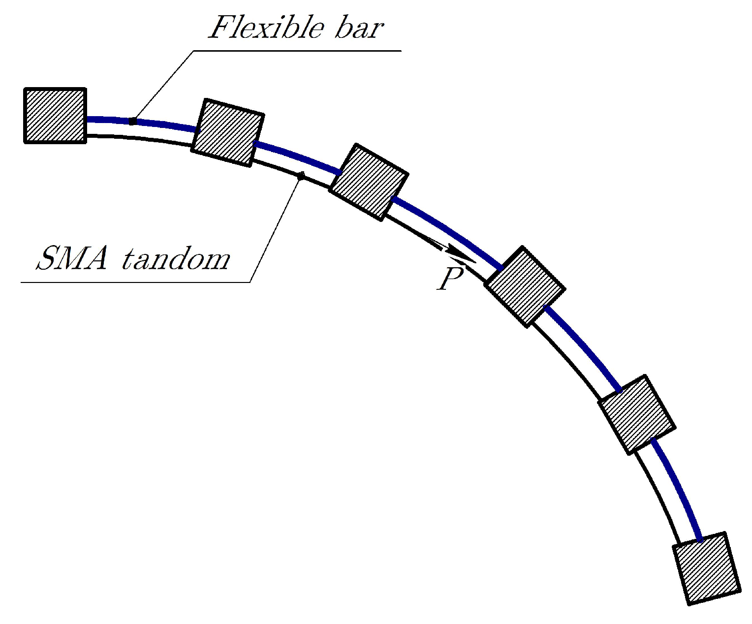
Figure 1. SMA-actuated flexible bar system.
Applsci 10 00471 g001
Figure 2. Free body diagram of the flexible bar: (a) initial (straight) state; (b) after deflection.
Applsci 10 00471 g002
Figure 3. The discrete model of n-rod.
Applsci 10 00471 g003
Figure 4. The angular position of flexible bar without control.
Applsci 10 00471 g004
Figure 5. Output angles of the flexible bar.
Applsci 10 00471 g005
Figure 6. The overall current input i = i 0 + i c o m p .
Applsci 10 00471 g006
Figure 7. The two components of the current input.
Applsci 10 00471 g007
Figure 8. Sliding surface of the proposed sliding mode control (SMC).
Applsci 10 00471 g008