1. Introduction
The extensive application of prestressed concrete (PSC) in structures can be credited to its structural and economic efficiency. In the PSC structure, the tendon plays a critical role to introduce prestress. The tendon is anchored to the concrete member at its ends and is inserted in a duct generally made of HDPE (High Density PolyEthylene) duct filled with grout to protect it from external ingress. However, the corrosion of the prestressing tendon accelerates in corrosive environments as the tension force becomes higher [
1]. There is a long list of structures that suffered severe degradation or even collapse because of the rupture or sectional loss of the corroded tendons’ strands [
2,
3]. Following the risk of such corrosion-induced damages, Germany and Japan implemented large-scale investigations on their PSC bridge inventories, which made it possible to detect numerous damages, from minor damage like early corrosion to severe damage like tendon failure [
4,
5].
The common causes of damage in the external tendon of PSC structures are known to be the low quality of grouting, the formation of air voids in the duct, and the chemical reaction of deicing chemical and chloride ion [
6,
7]. For example, corrosion of the tendons near their anchorage and cracks in the HPDE duct occurred at the Mid-Bay Bridge, Florida, USA, in 2000. One external tendon failed completely, another one experienced partial damage, a tendon suffered severe corrosion near its anchorage, and huge quantities of air voids were found in the ducts at mid-span and around their anchorages [
8]. In 2007, two tendons among the 480 tendons with grouted post-tensioned strands of Varina Enon Bridge, Virginia, USA, were replaced because of the formation of voids at their high ends which compromised the corrosion protection of the tendons [
9]. In 2016, an external tendon of Jeongneungcheon Bridge, Seoul, Korea, broke due to corrosion and the investigation could attribute it to the poor quality of the grouting [
10,
11,
12]. Later in 2019, corrosion literally exploded a 1000-ft cable on Wando River Bridge, South Carolina, USA, and sent scraps of grout and plastic as far as 30 m. The corrosion was caused by water seeping through the concrete deck [
13]. From these examples, the poor quality of the grouting in the PSC structure appears to be one major initiator of the corrosion or damage of the tendon. Periodic non-destructive evaluation (NDE) of the PSC structure is thus necessary for proper maintenance, and repair shall be implemented when the sectional loss reaches a definite level. Accordingly, the FHWA guideline(FHWA-HRT-13-027) states that the tendon must be replaced when the sectional loss exceeds 5% [
14].
This study pays attention to the non-destructive method to detect the change of the magnetic flux induced by the delivered magnetic field at the sectional loss area. Typical NDE methods delivering the magnetic field to the tendon are RMF (Remnant Magnetic Field), MFL (Magnetic Flux Leakage), and IMF (Induced Magnetic Field). These methods have shown the potential to evaluate the corrosion in the tendon section [
15,
16].
The disadvantage of the MFL method is that the Hall sensor measuring the leakage of the magnetic field is sensitive to the distance to the damage in the tendon. In other words, a weak signal from the Hall sensor cannot tell if the damage exists or if the distance to the intact tendon from the Hall sensor is far. According to the research using the MFL method on the external tendon, the existence of the sectional loss was well identified, but the difference between the estimated amount of sectional loss and the actual amount of the sectional loss was bigger as the amount of sectional loss increased [
17]. In another study for improving the MFL method, a method to measure the residual flux leakage induced by a permanent magnet was sensitive to the magnetization of the tendon [
18].
Another method proposed to measure the variation of the total magnetic field flux through the yoke rather than measuring the magnetic field leakage is MMF (Main Magnetic Flux). Since the MMF method can quantify the section loss of the tendon, it can be utilized in combination with the MFL method [
19]. Although the MMF method basically estimates the relative sectional loss, a method to figure out the absolute sectional loss by measuring the maximum and minimum of the magnetic flux change after delivering a strong bi-polar magnetic field to the tendon was proposed [
20]. Another study proposed to quantify the sectional loss by comparing the slope of the B-H loop with the reference slope [
21]. However, there was a difficulty in distinguishing the slope change resulting from the sectional loss and the tensile stress in the tendon.
The IMF method that is conceptually similar to the MMF method has shown a capability of detecting the damage location but there remains some doubt about the quantification of the damage [
22]. In addition, another method called spontaneous MFL was suggested to estimate the sectional loss by measuring the magnetic flux delivered by the Earth’s magnetic field instead of an artificial magnetic field to the tendon [
23,
24]. However, the leaked magnetic flux was so small that an extremely sensitive magnetic sensor had to be used to measure it and the method also required separating the measured signal from the noise and the external magnetic field source.
For the external tendon of the PSC structure, a heavy magnetizing system using a yoke for NDE is not suitable practically. It is also difficult to move the magnetizing system along the length of the tendon with a constant speed. Accordingly, this research adopts a simple solenoid to generate the magnetic field instead of the heavy yoke. In this framework, when the DC (direct current) is delivered to the solenoid, the induced voltage of the secondary coil related to the sectional change can be influenced by the moving speed of the device. Therefore, the AC (alternating current) is delivered to the primary coil to reduce the effect of the moving speed of the device and generate larger induced voltage in the secondary coil so that the flux leakage can be measured easily. The proposed method is expected to identify the sectional damage of the external tendon effectively by increasing the sensitivity of the secondary coil.
This paper proposes a novel damage-detecting method for an external tendon of PSC structures using a solenoid-shaped device. The principle of detecting sectional loss using a magnetic field is explained in
Section 2, and the experimental demonstration of the method is presented in
Section 3. The discussion of the experimental results and the conclusion of the research are drawn in
Section 4 and
Section 5.
2. TFL Method
The proposed TFL (Total Flux Leakage) method employs a solenoid similar to the EM (electromagnetic) sensor with a primary and secondary coil in order to estimate the sectional loss in the external tendon. The EM sensor was introduced to measure the residual stress in the tendon for NDE. The EM sensor consists of the primary coil to generate a magnetic field on the external tendon and the secondary coil installed at the center to detect the generated magnetic field. The governing equation of the EM sensor is well established [
25,
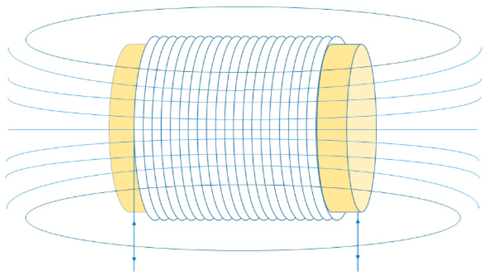
26]. Once a current is passed through the primary coil installed at the surface of HDPE duct of the external tendon, a magnetic field is generated inside and outside of the duct as shown in
Figure 1.
If a ferromagnetic material like the tendon is placed inside the duct along the longitudinal direction of the solenoid as shown in
Figure 2, and if the tendon is intact, the magnetic flux developed by the current in the primary coil will be distributed along the longitudinal direction of the tendon. From the perspective of magnetic material, the grout filling the external tendon has the same relative permeability with the air (μ
r = 1) and has thus no effect on the magnetic flux developed by the current in the primary coil.
If, additionally, a secondary coil is installed at the center of the solenoid as shown in
Figure 3a, any change in the magnetic flux can be detected by the change in the induced voltage in the secondary coil. Unlike the undamaged tendon case (
Figure 3a), when the tendon suffers partial damage like a sectional loss due to the rupture of some strands, a part of the magnetic flux around the damaged area is absorbed by the neighboring and undamaged strands and the remaining part of the magnetic flux is leaked (
Figure 3b). In such a case, the secondary coil around the damaged area detects the remaining magnetic flux that has not been leaked.
The electromotive force of the secondary coil induced by the current in the primary coil of the solenoid is expressed in Equation (1). The induced electromotive force,
, is simply the product of the number
of turns in the secondary coil and
, the first time derivative of the magnetic flux. Note that
acts in the direction opposite the change of the magnetic flux. The magnetic flux
is represented as the integration of the magnetic flux density,
, over the total internal cross-sectional area,
, of the solenoid.
where the total internal cross-sectional area of the solenoid
;
is the cross-sectional area of air in the cross-section of the solenoid;
is the cross-sectional area of the HDPE duct in the cross-section of the solenoid;
is the cross-sectional area of concrete in the cross-section of the solenoid; and,
is the cross-sectional area of the tendon in the cross-section of the solenoid.
When a time-variant AC flows in the primary coil of the solenoid, the magnetic field changes together and results in the change of the magnetic flux around the solenoid. The magnitude of the induced electromagnetic field is a function of
. Since
,
and
in
can be assumed as constants
, the induced electromotive force a function of
. Compared to the permeability
of the ferromagnetic tendon, the permeability of the air, concrete, and HDPE duct is very small and practically identical to the permeability in vacuum,
. Considering that all the parameters at the exception of
are controllable or constant,
in Equation (1) can be expressed as a function of the area of the tendon,
as shown in Equation (2).
where
is magnetic field intensity.
Equation (2) indicates that the measured variation of the induced voltage in the second coil by moving the solenoid throughout the length of the external tendon gives a means to detect the change of the sectional area of the tendon.
3. Experiment
Recalling that the tendon is made up of a bundle of strands and each strand is made up of wires, the tendon considered in this study is made of fifteen 7-wire strands. The sectional loss of the external prestressing tendon is simulated as shown in
Figure 4 by the number of snapped strands and the length of the damage in the tendon. For the convenience of the experiment, the HDPE duct of the external tendon is replaced with a transparent acrylic duct having similar relative permeability to HDPE. The tendon is placed inside the acrylic duct, and the length of the damage near the center of the tendon is changed from 0 to 10 cm. The number of snapped strands is increased from one to three to observe the secondary coil output according to the amount of damage.
Table 1 describes the cases setup for the 3-strand damage case.
The device delivering the magnetic field to the external tendon and detecting the variation of the magnetic flux is made by the assemblage of two 37-cm long plastic half-cylinders as shown in
Figure 5a. The secondary coil with 18 turns is installed at the center of the frame for detecting the magnetic flux signal and the primary coil with 400 turns over a length of 30 cm is placed over the secondary coil to generate the magnetic field. The stability of the magnetic field along the longitudinal axis measured at the center of the cross section is verified in
Figure 5b by comparison with the theoretical values. However, the device in
Figure 5 is unsuitable for in situ inspection that needs frequent assembly and disassembly due to the large number of numerous turns.
Accordingly, our research team developed a mountable frame where the primary and secondary can be easily connected by plugging as shown in
Figure 6a to avoid the repeated winding of the coils in situ. This so-called wrapping solenoid-shaped device also exhibited stable magnetic field through the comparison of the measured and theoretical values (
Figure 6b). Nevertheless, the original setup of
Figure 5 is employed here for evaluating the feasibility of the TFL method in detecting the sectional loss in the external tendon. Research about the improved device shown in
Figure 6 will be implemented in the future to investigate its accuracy and performance. In addition, the operation of the solenoid-shape device with a battery will be tested in the future to verify the stableness of the device’s results with a less stable power supply for in situ inspection.
Although an automatic movement of the device can reduce the uncertainty from the inconstant moving speed of the device, the automation of the device movement is not considered in this study. In general, near the anchorage where is damages are often found, tendons are closely spaced with each other, and an available space that the device can use is limited. The automation equipment also increases the weight of the device that is another limitation for field application. Therefore, the device was designed to remove inessential function in order to fit into the limited space and weight. But the automation equipment can be installed without difficulty if necessary.
Figure 7 shows the external tendon specimen with the installed device. During the inspection, the distance travelled by the device along the axis of the tendon was measured in real time with respect to the reference point using a laser distance meter. An AC with frequency of 10 Hz and amplitude of ±0.6 A was delivered continuously to the primary coil of the device using the NI (National Instrument) equipment as shown in
Figure 8. The signal was generated by the LabVIEW program on a laptop and the NI PXI-5412 AWG (arbitrary waveform generator). The generated signal was magnified by the NF BP bipolar DC power supply. The output voltage from the secondary coil of the device was measured by the NI PXI-4462 DAQ (data acquisition) system. The device was moved manually and slowly along the length of the tendon by the operator without a specific power unit.
4. Results
Figure 9 shows a typical pattern of the output signal measured in the secondary coil in the case of damaged external tendon. As the AC is delivered to the primary coil, the output signal of the secondary coil has a form similar to the input signal delivered to the primary coil with the same frequency and is symmetric with reference to the horizontal axis. In the case where the DC is delivered to the primary coil instead of an AC and the moving speed of the device is irregular, undesired disturbance would occur in the induced voltage on the secondary coil. In this research, a sufficiently stable magnetic flux was generated by means of AC that inverted the direction of the power source as much as its frequency even though the operator was moving the device without specific speed control. Since the device was moved slowly from the left end to the right end of the external tendon, a very large number of positive and negative peaks of the secondary coil output signal was recorded according to the distance travelled during the total time of motion. The measured secondary coil output takes thus the form of the compressed sinusoidal wave along the horizontal axis shown in
Figure 9. Only the positive peaks were picked from the measured signal for the convenience of the analysis.
The peak curves of the voltage induced in the secondary coil in accordance with the change in length of one-strand damage of the external tendon are presented in
Figure 10. The lowest point in the curves corresponds the center of the damage length. The centerline of the damage length is shifted slightly to the right due to the fixed left end of the damage as shown in
Figure 4. It is observed that this phenomenon is reflected on the measured peak curves.
In the same manner, the peak curves of the voltage induced in the secondary coil in accordance with the change in length of two- and three-strand-damage of the external tendon are presented in
Figure 11 and
Figure 12, respectively. In addition, the secondary voltage reduction ratios of the one to three-strands damage with respect to the damage length are presented in
Figure 13. The damage detectable level in
Figure 13 was visually suggested as the peak curve for the 1-strand damage with 0 cm damage length in
Figure 10 is difficult to be distinguished and can be hidden if the signal to noise ratio decreases. The decrement ratio in
Figure 13 is the voltage change due to the damage to the voltage value just before the decrement.
The location of the sectional loss can be estimated simply and intuitively. Moreover, the change in the damage length is also well reflected in
Figure 10,
Figure 11 and
Figure 12. The reduction of the magnitude of the voltage induced in the secondary coil caused by the magnetic flux leaked from the damaged section that is not permeating the secondary coil shown in
Figure 3 can be clearly distinguished in the graphs. In addition, it appears that deeper and longer damage introduces stronger magnetic flux leakage as well as increases the magnitude of the decrement of the voltage induced in the secondary coil as shown in
Figure 13. The ratio of decrement in induced voltage of the secondary coil for all cases except for the 1-strand damage with a length of 0 cm case were above the designated damage detectable level. However, as such the case is neglectable as the external tendon is always in tension and the damage length would not be zero when cut.
The maximum peak curve of the voltage induced in the secondary coil measured by moving the device throughout the length of the external tendon can provide information about the damage location by identifying the variation of the curve. The reduction of the voltage induced in the secondary coil by the rupture of 1 or more strands or damage length of 2 cm or longer can be intuitively identified. Hence, this validates that the method measuring the change of the total flux can be used to detect damage in the external tendon. This result satisfies the FHWA guideline of tendon replacement at 5% sectional loss as well as the project’s detection accuracy of figuring out 1 out of 15 tendons.
The external tendon of the PSC structure has a limited profile and size inside the structure section unlike other cases with a complicated profile and size. Since the device wraps the entire section of the external tendon, the secondary coil can measure almost any change of the magnetic flux induced by the change of the sectional area inside the tendon. The proposed method has shown the potential to identify and quantify the sectional loss in the external tendon by using a solenoid-shaped device fed with AC and presenting a simple shape and light weight even though the uncertainty of the proposed method increases if a strong exterior magnetic source is close to the device or the power supply is unstable. The proposed TFL method offers the advantage of a low-power source which makes it convenient for actual NDE conditions in terms of portability and long-term usage.


