Article

Research on Dynamic Mechanical Properties and Constitutive Model of Basalt Fiber Reinforced Concrete after Exposure to Elevated Temperatures under Impact Loading

1
School of Civil Engineering, Chang’an University, Xi’an 710061, China
2
School of Geology Engineering and Geomatics, Chang’an University, Xi’an 710054, China
*
Authors to whom correspondence should be addressed.
Appl. Sci. 2020, 10(21), 7684; https://doi.org/10.3390/app10217684
Submission received: 16 September 2020 / Revised: 14 October 2020 / Accepted: 26 October 2020 / Published: 30 October 2020

Abstract

:
The dynamic mechanical properties of basalt fiber reinforced concrete (BFRC) with different fiber contents (0.0%, 0.1%, 0.2%, 0.3%, 0.4%), confining pressures (0 MPa, 5 MPa, 10 MPa, 15 MPa) and exposed to different temperatures (20 °C, 200 °C, 400 °C, 600 °C, 800 °C) were investigated by using a 50 mm split Hopkinson pressure bar (SHPB) apparatus, and the factors such as fiber content, temperature and confining pressure effect on the dynamic mechanical properties were analyzed. The results show that the dynamic peak stress increases first and then decreases with the increase of fiber content. At different temperatures, the peak stress and its corresponding strain correspond to different fiber content, and the optimal fiber content is between 0.1% and 0.3%. When the temperature was from 20 °C to 400 °C, the dynamic peak stress decreased less, while when the temperature reached 600 °C and 800 °C, the dynamic peak stress decreased greatly. The confining pressure can significantly increase the dynamic peak stress and change the crushing morphology of specimens. The damage variable was built based on the Weibull distribution. A dynamic damage constitutive model combining statistical damage and viscoelastic model was established based on component combination model. The fitting curve of this model fitted well with test curve by identifying fewer undetermined parameters compared with Zhu-Wang-Tang (ZWT) model; therefore, this model can well describe the dynamic properties of BFRC under impact load.

1. Introduction

Basalt fiber (BF) is a typical silicate fiber with outstanding high temperature resistance, good compatibility with cement and concrete, superior mechanical properties and high chemical stability [1,2,3]. The manufacturing process of BF consumes less energy and no additives, which makes it cheaper than glass or carbon fiber [4]. Basalt fibers have been used as concrete reinforcement due to their superior performance and a lot of research has been conducted on it. As a kind of concrete reinforced composite material, BFRC has higher strength, toughness and better impact resistance than ordinary concrete, because the randomly distributed fibers form networks to hinder the formation and expansion of micro and macro cracks [2,5,6,7,8]. Therefore, in recent years, the application of BFRC has been expanding continuously, such as underground engineering, protection engineering, etc. With the development of social economy and the expansion of application range, people put forward higher and higher requirements for concrete structures, such as impact, explosion, elevated temperature and other extreme loads on the structure. Heat damage is a common risk to the safety of concrete structure. The mechanical properties and durability of concrete materials after exposure to elevated temperatures will deteriorate [9]. In industrial building fires and nuclear power plant accidents, the structures not only are damaged by high temperatures, but also usually suffer the impact load caused by explosion, collapse of the superstructure, etc. [10]. So the research of the dynamic mechanical properties and constitutive model of BFRC under complex stress after exposure to high temperature is of great significance for the evaluation and repair of the damaged structure.
Compared with the study on static mechanical properties of BFRC [2,5,6,11,12,13], less studies on the dynamic mechanical properties and constitutive model have been conducted, mainly include: Xu [14], Li [15,16], Fan [17], Zhang et al. [18] studied the dynamic mechanical properties of BFRC, analyzed the influence factors of dynamic strength; Ren et al. [19,20] studied the fractal characteristics and dynamic characteristics of BFRC exposed to high temperature and analyzed the influencing factors such as strain rate, fiber content, temperature, porosity, etc. Li [21] and Liang et al. [22] conducted split Hopkinson pressure bar (SHPB) tests on concrete and analyzed the fractal dimension and energy dissipation of fragments. Whereas the research about dynamic mechanical properties of BFRC under the coupling action of elevated temperature and confining pressure have not been reported. Xu [23], Zhang et al. [18] established the BFRC dynamic constitutive model based on SHPB test and ZWT model, but the model needs many parameters to fit the test curve well.
Therefore, in this paper, a 50 mm split Hopkinson pressure bar (SHPB, produced by Luoyang Liwei Technology Co., Ltd., Luoyang, China) apparatus was used to investigate the dynamic mechanical properties of BFRC with different fiber contents (0.0%, 0.1%, 0.2%, 0.3%, 0.4%), and exposed to different temperatures (20 °C, 200 °C, 400 °C, 600 °C, 800 °C), the factors include strain rate, fiber content, confining pressure and temperature were analyzed based on the test results. A new constitutive model of BFRC which needs few parameters was established based on component combination model.

2. Experimental Procedure

2.1. Materials and Specimen Preparation

In this test, the mixing proportions (determined by the strength grade of C35 in Chinese standard) of concrete specimens are shown in Table 1. The ordinary Portland cement (strength grade of 42.5), the well graded coarse aggregate (grain diameter was 5–16 mm), the fine aggregate (continuously graded medium size sand with a fineness modulus of 2.42) and tap water was used. The performance parameters of basalt fiber are shown in Table 2. The volume fraction of basalt fibers are 0.1%, 0.2%, 0.3% and 0.4% respectively. The properties of fly ash are as follows: density 2.4 g/cm3, fineness 43 μm, moisture content about 5%. Considering that ready-mixed concrete with water reducer is often used in practical engineering, the naphthalene-based water reducer with 7~9 pH values and 20–35% water reduction rate is used in this test.
The BFRC was cast in the shape of a 150 mm × 150 mm × 150 mm cube. After 1 day curing at the room, the cubes were removed from molds and kept in water at 20 ± 2 °C for 28 days. Before the test, 50 mm × 25 mm cylinder specimens were made from cubes through coring, cutting process. To ensure that the non-parallelism and non-perpendicularity were less than 0.02 mm, the two end faces of the specimens were polished

2.2. Heating and Cooling

The artificial intelligence box-type resistance furnace (produced by Luoyang Sigma Furnace Industry Co., Ltd., Luoyang, China) was used as heating equipment and the temperatures were controlled by the computer, so the process of heating could be automatic and accurate. The maximum temperature of resistance furnace is 1000 °C. The target temperatures were 20 °C (room temperature), 200 °C, 400 °C, 600 °C, and 800 °C. The heating rate of resistance furnace was set at 10 °C/min [19]. Every target temperature was held constant for 2 h to achieve thermal steady state and also to make sure that the chemical and physical changes of specimens were more thorough.
Considering a fire is usually extinguished by using water in real situations and water cooling causes more severe deterioration in concrete compare with natural cooling [24], the specimens were cooled in the 1.0 m × 0.8 m × 0.4 m water tank immediately after the heating procedure. In order to eliminate the influence of water content, the specimens after soaking were placed in the air for 4 weeks.

2.3. SHPB System

A 50 mm diameter split Hopkinson pressure bar (SHPB) apparatus with 500 mm-long striker, 2500 mm-long incident bar and 2000 mm-long transmitted bar was used to test BFRC specimens, as shown in Figure 1. The properties of all the bars are shown in the Table 3. A high dynamic strain indicator (produced by Qinhuangdao Longke Measurement Technology Co., Ltd., Qinhuangdao, China) was used for data acquisition through the strain gauges mounted on the surface of the incident and transmitted bar. The technical parameters of high dynamic strain indicator are as follows: coefficient of strain (K) is 2.0, sensitivity (kp) is 1v/1000 μ ε . The confining pressure device applied pressure to specimens by means of hydraulic pressure and kept pressure stable. The pulse shaping technique [25] which could eliminate the high frequency oscillation, reduced the wave dispersion effects, and extended the rising time of the incident pulse was used in SHPB test. In this research, through the comparative analysis of the tests, the pulse shaper used copper sheets that were 1 mm in thickness and 25 mm, 20 mm, 15 mm in diameters corresponding different impact velocities: 5.4 m/s, 8.8 m/s, and 11.3 m/s.
During the impact process, the striker impacted incident bar through propelling by pressurized nitrogen gas. Impact wave passed through specimens form incident bar to transmitted bar and the specimens would be destroyed. Based on the theory of one-dimensional wave propagation, the stress, strain and strain rate of the specimens can be calculated by the following equations:
{ σ ( t ) = E 0 A 0 2 A s [ ε I ( t ) + ε R ( t ) + ε T ( t ) ] ε ˙ ( t ) = C 0 L s [ ε T ( t ) ε I ( t ) ε R ( t ) ] ε ( t ) = C 0 L s 0 t [ ε T ( t ) ε I ( t ) ε R ( t ) ] d t
where A 0 , E 0 , C 0 are cross-sectional area, elasticity modulus and longitudinal sound velocity of incident or transmitted bar, A s , L s are cross-sectional area and length of specimens, ε I ( t ) , ε T ( t ) and ε R ( t ) are incident pulse, transmitted pulse and reflected pulse, σ ( t ) , ε ( t ) and ε ˙ ( t ) are the stress, strain and strain rate of the specimens.

3. Test Results and Analysis

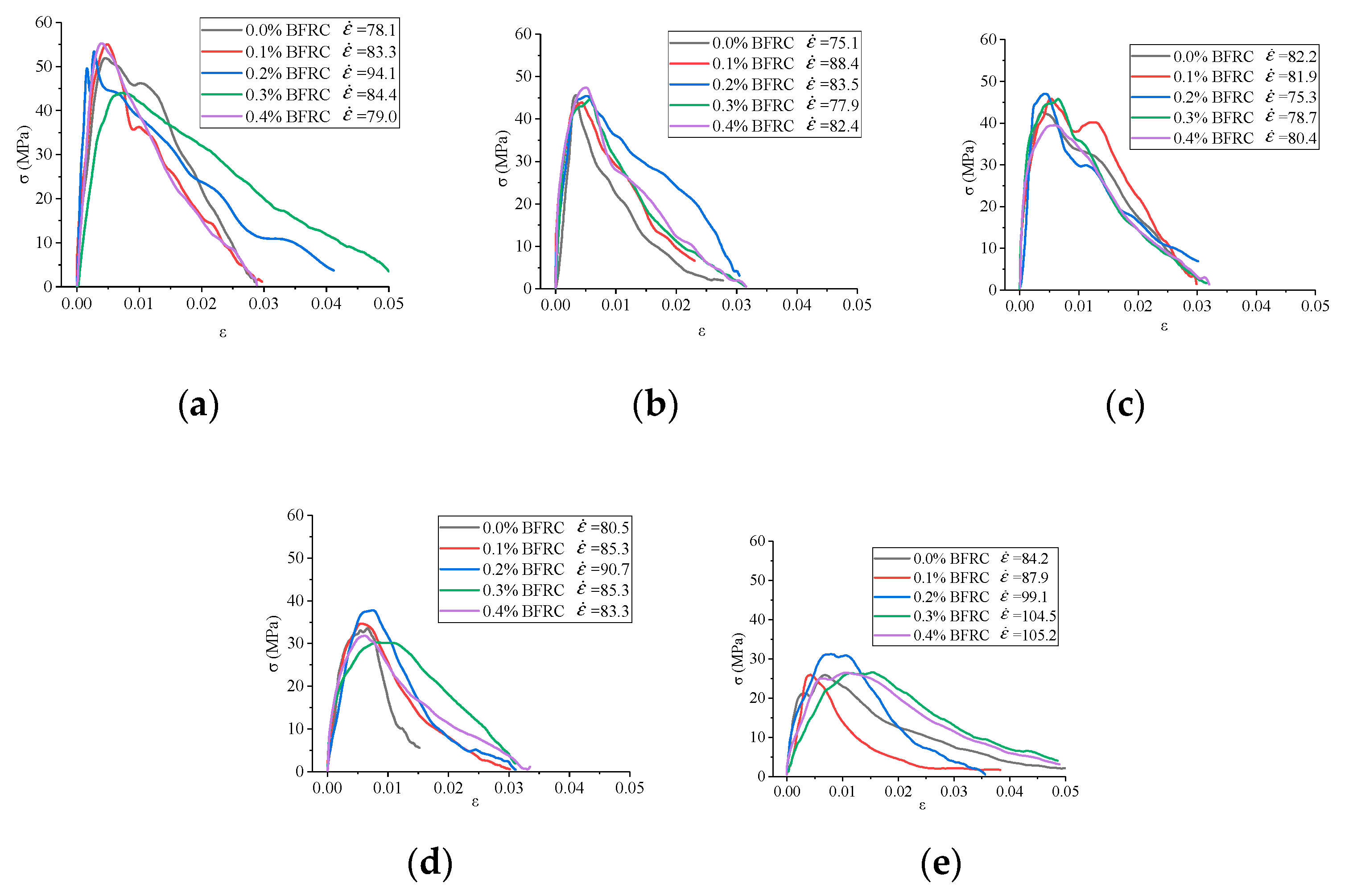
When the impact velocity is 8.8 m/s, the stress–strain curves of BFRC specimens for different fiber contents and temperatures are shown in Figure 2.

3.1. Influence Analysis of Fiber Content

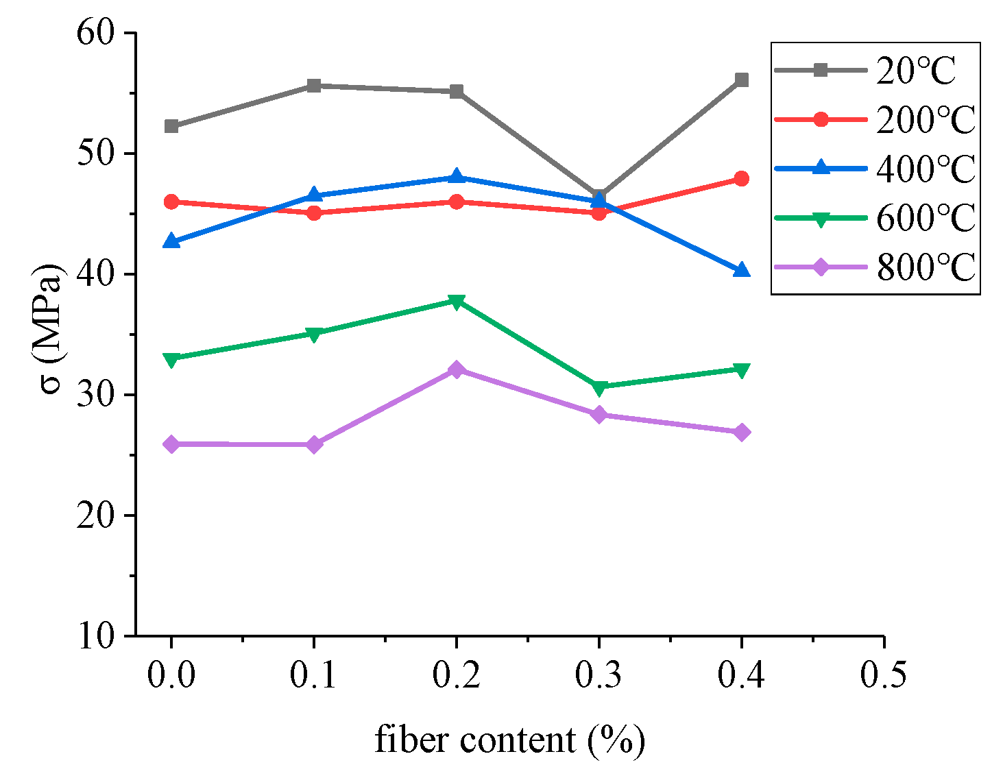
The variation rule between fiber content and stress peak strength is shown in Figure 3.
Figure 2 and Figure 3 show that the optimum fiber content is different at different temperatures. For example, at 20 °C, when the fiber content is 0.1%, the specimen has high strength and peak strain. At 200 °C, the dynamic peak stress is basically same under different fiber content. When the fiber content is 0.2%, the specimen has a higher peak strain. At 400 °C, the specimen has a high peak strain when the fiber content is 0.3% and high dynamic strength when the fiber content is 0.2%. At 600 °C, the specimen has high dynamic strength and peak strain simultaneously when the fiber content is 0.2%. At 800 °C, when the fiber content is 0.2%, the specimen has a higher dynamic strength, and when the fiber content is 0.3%, the specimen has a higher peak strain. To sum up, when the fiber content is between 0.1% and 0.3%, BFRC at different temperatures has higher dynamic strength and ductility. When the fiber content is low, the fiber crack resistance cannot be fully exerted, while when the fiber content is high, it is easy for the concrete to be stirred into a group during the concrete mixing process. In addition, when the temperature is between 400 °C and 800 °C, the dynamic peak stress increases firstly and then decreases with the change of fiber content.

3.2. Influence Analysis of Temperature

The appearance characteristics of the specimens after exposure to different temperatures when the fiber content is 0.2% are shown in the Figure 4.
As can be seen from Figure 4, when the temperature was 200 °C, the specimen had a complete appearance without obvious peeling and damage, and the color was roughly the same as that at 20 °C. At 400 °C, the skin of specimen was slightly peeled off, and the color showed light gray. At 600 °C, the peeling of the epidermis was more obvious, with slight cracks on the surface and a reddish color. At 800 °C, the peeling of epidermis was obvious, the surface had obvious cracks, and the reddish color deepened. When the temperature was 1000 °C, the specimen was broken into pieces and the color was red. The specimen was completely destroyed under the effect of temperature.
When the impact rate is 8.8 m/s and the fiber content is 0.2%, the crushing morphology of BFRC specimens after exposed to different temperatures are shown in Figure 5. It can be seen that the size of fragmentations became smaller and smaller as the temperature rose under impact loading.
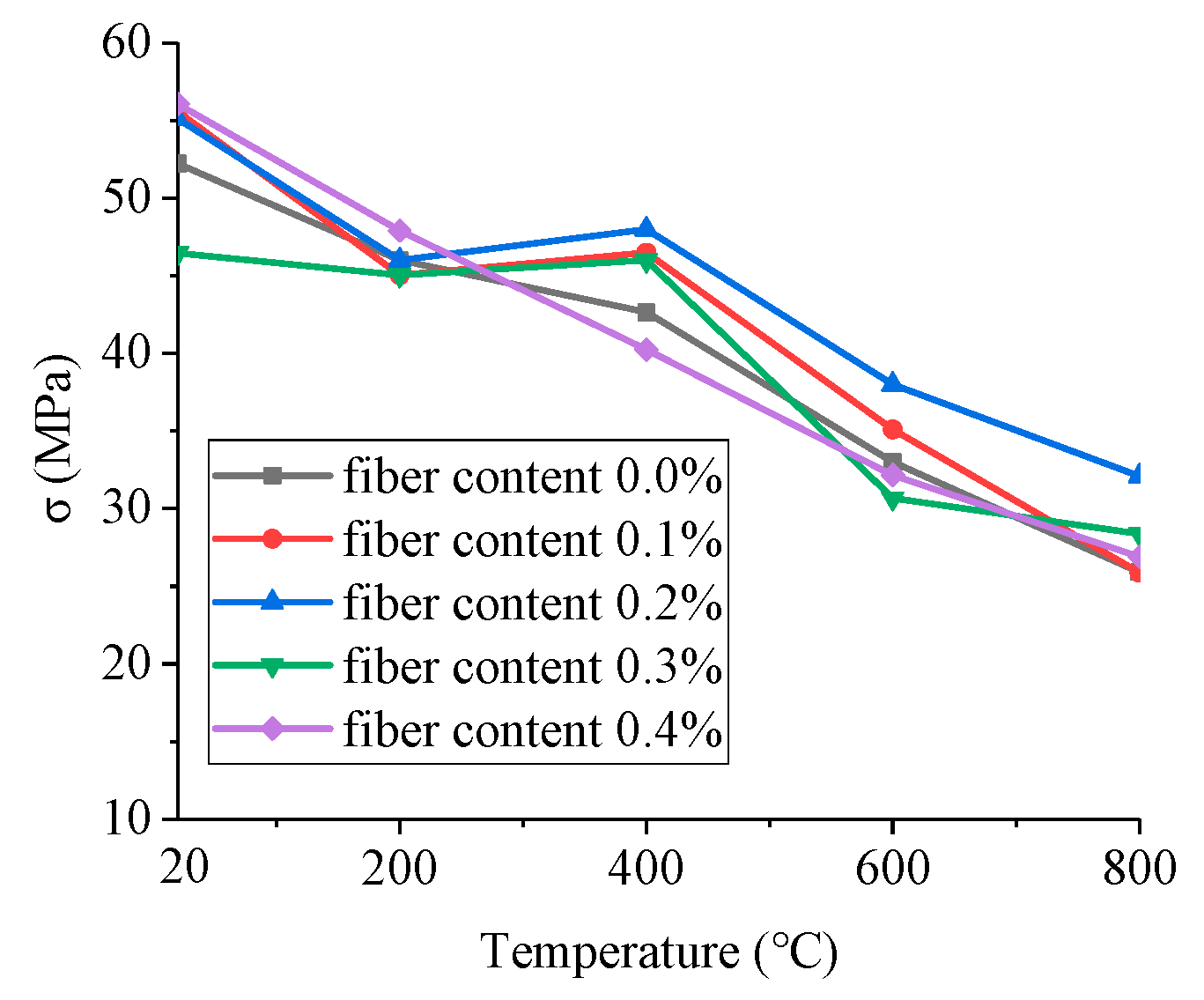
When the impact velocity is 8.8 m/s, the change curves between temperature and dynamic strength of BFRC specimens with different fiber content are shown in Figure 6.
Figure 3, Figure 5 and Figure 6 shows that the dynamic peak stresses of BFRC specimens gradually reduced as the temperature rose. The dynamic strengths of the ordinary concrete specimens at 200 °C, 400 °C, 600 °C and 800 °C were 88%, 81.7%, 44% and 36.5% of that at room temperature, respectively. When the fiber content was 0.2%, its corresponding proportion respectively: 83.5%, 93%, 77.4%, 58.3%, indicating that elevated temperature has significant damage to the dynamic mechanical properties of concrete. Compared with ordinary concrete, BFRC has lower damage. When the temperatures ranged from 20 °C to 400 °C, the peak strength decreased less than 20% compared with room temperature, which was consistent with the variation law of concrete strength after high temperature under quasi-static loading in reference [26]. But when the fiber contents were 0.1–0.3% and temperatures ranged from 200 °C to 400 °C, the peak strength increased slightly. When the temperature reached 600 °C and 800 °C, the peak stress greatly reduced. According to the microscopic studies of concrete after elevated temperature [27,28,29,30], it can be seen that when the temperatures were at 200–400 °C, micro-cracks and voids in the concrete caused by free water evaporation continued to develop, the C-S-H gel became decomposed simultaneously and the damage became more severe. But the interlock force between gels and aggregate became enhanced due to the contraction of C-S-H gel. In addition, the bridging effect of basalt fibers could limit and delay the development of micro-cracks and partially relieve stress concentration at the tips of cracks. Therefore, when the increase of crack resistance by fibers and interlock force exceeds the strength reduction caused by fracture development, the impact strength of specimens would increases under impact load. When the temperature exceeded 400 °C, the C-S-H gel became loose, calcium hydroxide and crystallization water inside concrete decomposed, cement mortar shrank significantly and aggregate expanded at the same time, the internal stress increased, the bonding surfaces between aggregate and cement mortar cracked. The above phenomena would lead to the destruction of the internal structure of concrete, and the strength would decrease sharply. When the temperature reached 900 °C, the limestone began to decompose and the aggregate was completely separated from the cement mortar, the concrete almost completely lost bearing capacity.

3.3. Influence Analysis of Confining Pressure

Stress–strain curves of specimens under different impact velocities and confining pressures are shown in Figure 7 and the crushing morphology (impact velocity: 11.3 m/s) are shown in Figure 8.
As can be seen from Figure 7, stress-strain curves presented the following characteristics:
(1) The rising section of the stress–strain curve with confining pressure was basically a straight line. Under the same impact velocity, the dynamic elastic modulus of specimens with confining pressure were relatively close, and their value were about 20 GPa~150 GPa, which increased with the impact velocity. The higher the impact velocity, the more obvious the strengthening effect of confining pressure.
(2) When the strain rate was about 27–42 s−1, the stress–strain curves of specimens with confining pressure showed type of π and had a yield platform. The corresponding strain of the peak stress platform was about 3–7 × 10⁻³, which were greater than those without confining pressure, indicating that when the strain rate was less than 42 s−1, the ductility of basalt fiber concrete was enhanced under confining pressure.
(3) With the increase of strain rate, the variation amplitude of the peak stress also increases. Figure 7a shows that the peak stress increases from 54.1 MPa to 85.8 MPa, increasing by 58.6% with confining pressure increases from 0 MPa to 15 MPa at impact velocity of 5.4 m/s. Figure 7b shows that the peak stress increases from 58.1 MPa to 136.6 MPa, increasing by 135.1% at impact velocity of 8.8 m/s. Figure 7c shows that the peak stress increases from 63.7 MPa to 162.1 MPa, increasing by 154.5% at impact velocity of 11.3 m/s.
Figure 8 shows that when the impact velocity was 11.3 m/s, the specimen without confining pressure was broken, while the specimens with confining pressure remained intact, but the edge part peeled off. When the confining pressure was 5 MPa, the edge peeled off obviously. When the confining pressure was 5 MPa, a penetrating crack appeared in the center of the specimen, but it was not broken into pieces under the action of the confining pressure device. When the confining pressure was 10 MPa and 15 MPa, cracks appeared on the surface but did not penetrate the whole specimen. It also can be seen that the peak stress of specimens measured are not the maximum because the specimens were not completely broken under 10 MPa and 15 MPa.

4. Dynamic Damage Constitutive Model

4.1. Visco-Elastic Damage Constitutive Model (V-E Model)

As a heterogeneous, anisotropic multiphase composite material, there were many initial defects such as micro-cracks and micro-holes in the interior of concrete, and the strength distribution was not uniform. In the process of dynamic loading, micro-cracks and micro-holes were formed, developed and aggregated to form macroscopic cracks, which eventually led to breakage. Eibl et al. [31] proposed that the concrete damage was caused by the development and accumulation of cracks, which was a continuous process. The distribution of cracks conformed to the Weibull distribution. Meanwhile, under the dynamic load, pore water in concrete had viscosity effect (Stefan effect) [32].
For the convenience of analysis, it was assumed that concrete was divided into microelements with different defects. The size of microelements should be very small and meet the dual nature of size [33]. Their dimensions were large enough to contain enough microcracks, microholes and other micro information on the microscopic level. Meanwhile, their size was small enough to be considered as a particle of continuous damage mechanics on the macroscopic level.
As the concrete unit had both viscosity effect and statistical damage characteristics, the BFRC specimens can be set up as a union of viscous component and damaged component, as shown in Figure 9.
Where, σ is the axial stress applied to the microelement. From the parallel relation between the damaged component D and the viscous component η , σ is the sum of the two parts’ stresses, therefore;
σ = E ε + η ε ˙
According to the strain equivalence principle of Lemaitre, the strain produced by the damaged material under the action of effective stress is equivalent to that produced by the same material under the non-destructive injury. Moreover, the damage only occurs on the spring element, and not on the viscous body. Accordingly, the following concrete damage constitutive model was established:
σ = ( 1 D ) E ε + η ε ˙
The damage of concrete was continuous under the action of loads. Assume the strength of each microelement conforms to probability distribution φ ( ε ) , then:
d D d ε = φ ( ε )
φ ( ε ) follows the three-parameter Weibull distribution:
φ ( ε ) = m α ( ε γ ) m 1 exp [ ( ε γ ) m α ]
where, α , m , γ were scale parameter, shape parameter and position parameter respectively. According to Formulas (1) and (2), the damage factor D was:
D = γ ε φ ( x ) d x = m α γ ε ( x γ ) m 1 exp [ ( x γ ) m α ] d x = exp [ ( x γ ) m α | γ ε = 1 exp [ ( ε γ ) m α ]
As concrete contains microcracks with initial damage, take γ = 0 . Then;
D = 1 exp [ ε m α ]
Substituting Equation (7) into Equation (3), the damage constitutive model of concrete can be obtained as follows:
σ = ( 1 D ) E ε + η ε ˙ = exp [ ε m α ] E ε + η ε ˙

4.2. The Fitting of Parameters

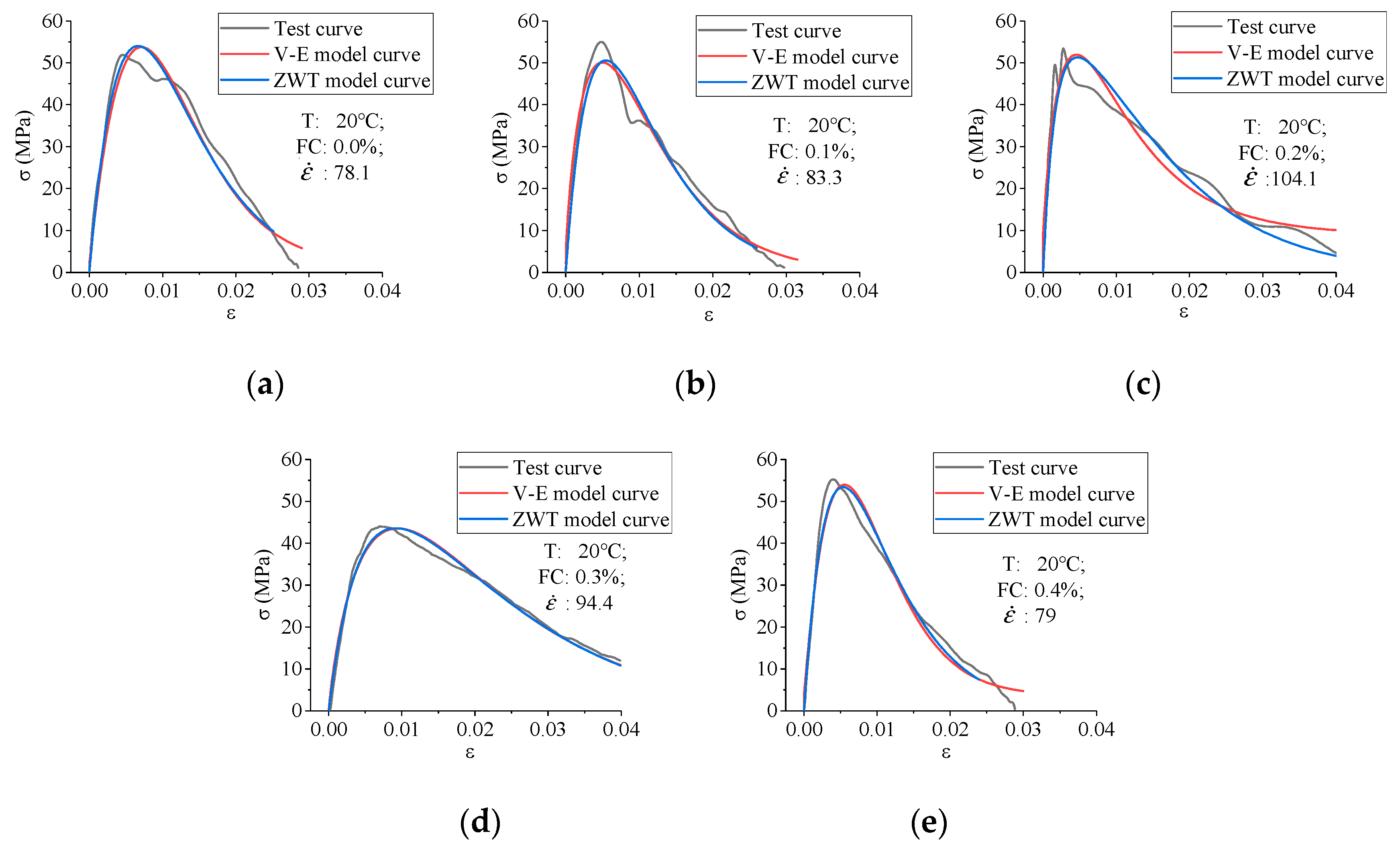
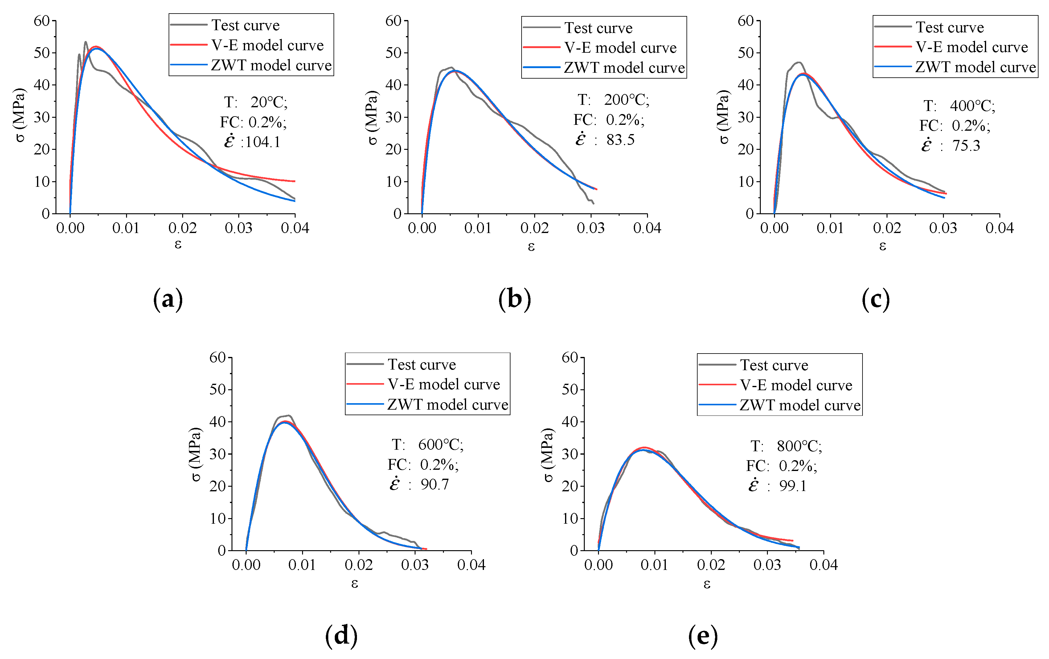
We calculate the stress–strain curves of specimens based on the dynamic statistical damage constitutive model established above, and compare with the test curves. The parameter inversion results were shown in Table 4, and the comparison results of the curves were shown in Figure 10 and Figure 11.
Table 4, and Figure 10 and Figure 11 show that the model calculated curves of specimens fitted well with the test curves, showing that the constitutive model established can basically accurately describe the dynamic mechanical response law of BFRC.

4.3. Comparative Analysis with ZWT Model

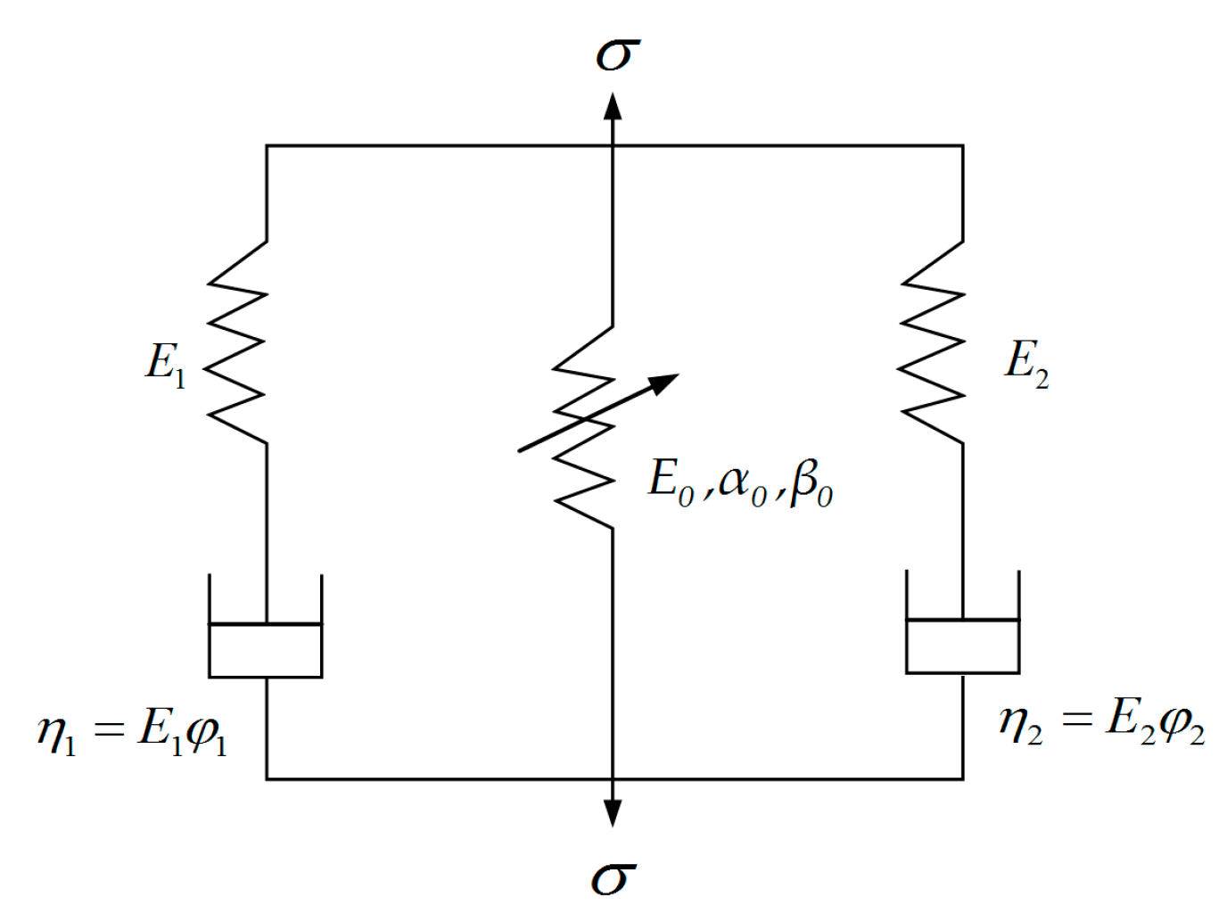
ZWT model [34,35] is a nonlinear viscoelastic constitutive model and is suitable for the strain rate of 10−4 s−1–103 s−1. Researchers have conducted some studies on the application of ZWT model in the dynamic constitutive model of concrete. The ZWT model is shown in Figure 12.
The ZWT model is composed of two Maxwell medium and a nonlinear elastomer parallelly. The two Maxwell models ( E 1 , φ 1 and E 2 , φ 2 ) describe the viscoelastic response of BFRC under quasi-static and high strain rates load respectively. The ZWT model expression is as follows:
σ = E 0 ε + α 0 ε 2 + β 0 ε 2 + E 1 0 t ε ( τ ) exp ( t τ φ 1 ) d τ + E 2 0 t ε ( τ ) exp ( t τ φ 2 ) d τ
where, E 0 , E 1 , φ 1 , E 2 , φ 2 are material constants, E 0 , α 0 , β 0 are elastic constants, E 1 , E 2 are linear elastic modulus, φ 1 , φ 2 are relaxation times.
The first part of nonlinear elasticity in the above equation can be regarded as linear elasticity and only the first term can be taken due to the strain of the specimens is tiny and the stress–strain curve under the quasi-static load is approximately linear at elastic range. The strain rate ( ε ˙ ) of the SHPB test can be approximately regarded as a constant. Therefore, the expression of ZWT model can be written as follows:
σ = ( 1 D ) [ E 0 ε + E 1 φ 1 ε ˙ ( 1 e ε ε ˙ φ 1 ) + E 2 φ 2 ε ˙ ( 1 e ε ε ˙ φ 2 ) ] = exp [ ε m α ] [ E 0 ε + E 1 φ 1 ε ˙ ( 1 e ε ε ˙ φ 1 ) + E 2 φ 2 ε ˙ ( 1 e ε ε ˙ φ 2 ) ]
The parameter inversion results were shown in Table 5, and the comparison results of the curves were shown in Figure 10 and Figure 11.
Compared with the ZWT model, the visco-elastic damage constitutive model has the following characteristics:
(1)
The V-E model needs fewer parameters to fit the test curve well.
(2)
The expression of the V-E model is simpler, so it has better practicability.
(3)
The deficiency of the V-E model is the need for strain rate data, while the ZWT model only needs average strain rate ( ε ˙ ), except for stress and strain data.

5. Conclusions

The dynamic mechanical properties of BFRC were investigated by using a SHPB apparatus. The influence factors including confining pressure, fiber content and temperature were analyzed. A new constitutive model was established and its practicability was proved. Based on the experimental results and the analyses, the following conclusions can be drawn:
  • At different temperatures, the optimum fiber content of BFRC is different. When the fiber content is between 0.1% and 0.3%, BFRC has higher dynamic strength and ductility. The mechanical properties of BFRC can’t reach the optimal level whether the fiber content is too low or too high.
  • The dynamic peak stresses of BFRC specimens gradually reduce and the crush degree increases as the temperature rises. High temperature has a remarkable damage effect on the dynamic mechanical properties of concrete, especially when the temperature is above 400 °C, the peak stress will be greatly reduced. However, the peak strength decreased less than 20% when the temperatures ranged from 20 °C to 400 °C.
  • The confining pressure has a noticeable effect on the dynamic mechanic properties of BFRC. It can improve the dynamic peak stress, ductility and dynamic elastic modulus, change the crushing morphology and reduce the degree of crushing fragment.
  • Compared with the ZWT model, the visco-elastic damage constitutive model was established in this paper can fit with test curves very well with fewer parameters, so the V-E model has better practicability.

Author Contributions

Conceptualization: W.L. and J.Z. Methodology: W.L., Y.L. and Y.Z. Formal analysis: W.L., Y.L., Z.W. and Y.Y. Writing—original draft preparation: W.L. Writing—review and editing: W.L. All authors have read and agreed to the published version of the manuscript.

Funding

This work was carried out in School of Civil Engineering at Chang’an University, and supported by the Postdoctoral Science Foundation Project of China (2020T130567, 2016M602736), and the Fundamental Research Funds for the Central Universities, CHD (300102269107), Natural Science Foundation of Shaanxi Province (2020JQ-373), National Natural Science Foundation of China (No. 51878056), Social Development Foundation for Science and Technology Planning Project of Shaanxi Province (2019SF-256).

Conflicts of Interest

The authors declare no conflict of interest.

References

  1. Sim, J.; Park, C.; Moon, D.Y. Characteristics of basalt fiber as a strengthening material for concrete structures. Compos. Part B Eng. 2005, 36, 504–512. [Google Scholar] [CrossRef]
  2. Jiang, C.H.; Fan, K.; Wu, F.; Chen, D. Experimental study on the mechanical properties and microstructure of chopped basalt fiber reinforced concrete. Mater. Des. 2014, 58, 187–193. [Google Scholar] [CrossRef]
  3. Wei, B.; Cao, H.L.; Song, S.H. Tensile behavior contrast of basalt and glass fibers after chemical treatment. Mater. Des. 2010, 31, 4244–4250. [Google Scholar] [CrossRef]
  4. Fiore, V.; Scalici, T.; Bella, G.D.; Valenza, A. A review on basalt fibre and its composites. Compos. Part B Eng. 2015, 74, 74–94. [Google Scholar] [CrossRef]
  5. Padmanabhan, L.; Sara, Y.K.; Sreekanta, D. Mechanical properties of fiber-reinforced concrete made with basalt filament fibers. J. Mater. Civ. Eng. 2015, 27, 04015015. [Google Scholar]
  6. John, B.; Sreekanta, D.; Sara, Y.K.; Craig, T. Mechanical behaviour of basalt fibre reinforced concrete. Constr. Build. Mater. 2016, 124, 878–886. [Google Scholar]
  7. Wang, Y.G.; Li, S.P.; Peter, H.; Fan, Y.H. Mechanical properties and microstructure of basalt fibre and nano-silica reinforced recycle concrete after exposure to elevated temperatures. Constr. Build. Mater. 2020, 247, 118561. [Google Scholar]
  8. Wang, Z.L.; Shi, Z.M.; Wang, J.G. On the strength and toughness properties of SFRC under static-dynamic compression. Compos. Part B Eng. 2011, 42, 1285–1290. [Google Scholar] [CrossRef]
  9. Xu, J.Y.; Liu, J.; Li, Z.W.; Bai, E.L.; Ren, W.B. Impact mechanical properties of concrete at and after exposure to high temperature. J. Build. Mater. 2013, 16, 1–5. [Google Scholar]
  10. Wang, Z.H.; Xu, J.Y.; Wang, T.J.; Meng, B.X.; Liu, G.J. Research on biaxial dynamic mechanical properties of concrete after high temperature under combined static and dynamic loads. J. Civ. Environ. Eng. 2020, 42, 1–8. [Google Scholar]
  11. Dias, D.P.; Thaumaturgo, C. Fracture toughness of geopolymeric concretes reinforced with basalt fibers. Cem. Concr. Compos. 2005, 27, 49–54. [Google Scholar] [CrossRef]
  12. Muazzam, G.S.; Wael, A.; Alaa, T.; Khaled, A. Sustainable alternative aggregates: Characterization and influence on mechanical behavior of basalt fiber reinforced concrete. Constr. Build. Mater. 2020, 255, 119365. [Google Scholar]
  13. Ayub, T.; Shafiq, N.; Nuruddin, M.F. Mechanical properties of high-performance concrete reinforced with basalt fibers. Procedia Eng. 2014, 77, 131–139. [Google Scholar] [CrossRef] [Green Version]
  14. Xu, J.Y.; Fan, F.L.; Bai, E.L.; Liu, J.Z. Study on dynamic mechanical properties of basalt fibre reinforced concrete. Chin. J. Undergr. Space Eng. 2010, 6, 1665–1671. [Google Scholar]
  15. Li, W.M.; Xu, J.Y. Mechanical properties of basalt fiber reinforced geopolymeric concrete under impact loading. Mater. Sci. Eng. A 2009, 505, 178–186. [Google Scholar] [CrossRef]
  16. Li, W.M.; Xu, J.Y. Impact characterization of basalt fiber reinforced geopolymeric concrete using a 100-mm-diameter split Hopkinson pressure bar. Mater. Sci. Eng. A 2009, 513–514, 145–153. [Google Scholar] [CrossRef]
  17. Fan, F.L.; Ye, X.H.; Xu, J.Y.; Li, W.M.; Chen, Y. Dynamic constitutive relation of basalt fiber reinforced concrete under impact loading. J. Vib. Shock 2010, 29, 110–114. [Google Scholar]
  18. Zhang, H.; Wang, B.; Xie, A.Y.; Qi, Y.Z. Experimental study on dynamic mechanical properties and constitutive model of basalt fiber reinforced concrete. Constr. Build. Mater. 2017, 152, 154–167. [Google Scholar] [CrossRef]
  19. Ren, W.B.; Xu, J.Y.; Su, H.Y. Dynamic compressive behavior of basalt fiber reinforced concrete after exposure to elevated temperature. Fire Mater. 2016, 40, 738–755. [Google Scholar] [CrossRef]
  20. Ren, W.B.; Xu, J.Y.; Bai, E.L.; Fan, J.S. Dynamic mechanical properties of basalt fiber reinforced concrete after elevated temperature. Explos. Shock Waves 2015, 35, 36–42. [Google Scholar]
  21. Li, Y.; Zhai, Y.; Liu, X.Y.; Liang, W.B. Research on fractal characteristics and energy dissipation of concrete suffered freeze-thaw cycle action and impact loading. Materials 2019, 12, 2585. [Google Scholar] [CrossRef] [Green Version]
  22. Liang, W.B.; Zhao, J.H.; Li, Y.; Zhai, Y. Research on fractal characteristics and energy dissipation of basalt fiber reinforced concrete after exposure to elevated temperatures under impact loading. Materials 2020, 13, 1902. [Google Scholar] [CrossRef] [PubMed]
  23. Xu, J.Y.; Li, W.M.; Huang, X.M.; Li, P. Dynamic constitutive model of basalt fiber reinforced geopolymeric concrete. Eng. Mech. 2010, 27, 111–116. [Google Scholar]
  24. Luo, X.; Sun, W.; Chan, S.Y.S.N. Effect of heating and cooling regimes on residual strength and microstructure of normal strength and high-performance concrete. Cem. Concr. Res. 2000, 30, 379–383. [Google Scholar] [CrossRef]
  25. Frew, D.J.; Forrestal, M.J.; Chen, W. Pulse shaping techniques for testing brittle materials with a split Hopkinson pressure bar. Exp. Mech. 2002, 42, 93–106. [Google Scholar] [CrossRef]
  26. Poon, C.S.; Azhar, S.; Anson, M.; Wong, Y.L. Comparison of the strength and durability performance of normal—and high—strength pozzolanic concretes at elevated temperatures. Cem. Concr. Res. 2001, 31, 1291–1300. [Google Scholar] [CrossRef]
  27. Khoury, G.A. Effect of fire on concrete and concrete structures. Prog. Struct. Eng. Mater. 2000, 2, 429–447. [Google Scholar] [CrossRef]
  28. Arioz, O. Effects of elevated temperatures on properties of concrete. Fire Saf. 2007, 42, 516–522. [Google Scholar] [CrossRef]
  29. Li, N.B.; Shi, X.D.; Xiao, M.H. Experimental investigation on compressive strength decaying behaviors of concrete after elevated temperature. Build. Sci. 2007, 23, 58–61. [Google Scholar]
  30. Borhan, T.M. Properties of glass concrete reinforced with short basalt fibre. Mater. Des. 2012, 42, 265–271. [Google Scholar] [CrossRef]
  31. Eibl, J.; Schmidt-Hurtienne, B. Strain-rate-sensitive constitutive law for concrete. J. Eng. Mech. 1999, 125, 1411–1420. [Google Scholar] [CrossRef]
  32. Rossi, P. A physical phenomenon which can explain the mechanical behavior of concrete under high strain rates. Mater. Struct. 1991, 24, 422–424. [Google Scholar] [CrossRef]
  33. Liu, J.Z.; Xu, J.Y.; Lv, X.C.; Wang, Z.D.; Zhang, L. Study on dynamic behavior and damage constitutive model of rock under impact loading with confining pressure. Eng. Mech. 2012, 29, 55–63. [Google Scholar]
  34. Chen, J.Y.; Wang, L.L. Rate-dependent constitutive equation of cement mortar. J. Ningbo Univ. (NSEE) 2000, 2, 1–5. [Google Scholar]
  35. Zhu, Z.X.; Xu, D.B.; Wang, L.L. Thermoviscoelastic constitutive equation and time-temperature equivalence of epoxy resin at high strain rates. J. Ningbo Univ. 1988, 1, 58–68. [Google Scholar]
Figure 1. Schematic diagram of split Hopkinson pressure bar (SHPB) apparatus.
Applsci 10 07684 g001
Figure 2. The stress–strain curves of basalt fiber reinforced concrete (BFRC) for different fiber contents and temperatures when the impact velocity is 8.8 m/s. (a) Temperature: 20 °C; (b) temperature: 200 °C; (c) temperature: 400 °C; (d) temperature: 600 °C; and (e) temperature: 800 °C.
Applsci 10 07684 g002
Figure 3. The variation rule between fiber content and stress peak strength.
Applsci 10 07684 g003
Figure 4. The appearance characteristics of the specimens after exposed to different temperatures.
Applsci 10 07684 g004
Figure 5. The crushing morphology of BFRC specimens after exposed to different temperatures.
Applsci 10 07684 g005
Figure 6. Temperature effect on the dynamic peak stress of BFRC specimens with different fiber contents.
Applsci 10 07684 g006
Figure 7. Stress–strain curves of specimens under different impact velocities and confining pressures. (a) Impact velocity: 5.4 m/s; (b) impact velocity: 8.8 m/s; and (c) impact velocity: 11.3 m/s.
Applsci 10 07684 g007
Figure 8. The crushing morphology of specimens under different confining pressures. (impact velocity: 11.3 m/s).
Applsci 10 07684 g008
Figure 9. Visco-elastic damage constitutive model.
Applsci 10 07684 g009
Figure 10. The comparison between test curves and fitting curves with different fiber contents (temperature: 20 °C, impact velocity: 8.8 m/s). (a) Fiber content: 0.0%; (b) fiber content: 0.1%; (c) fiber content: 0.2%; (d) fiber content: 0.3%; (e) and fiber content: 0.4%.
Applsci 10 07684 g010
Figure 11. The comparison between test curves and fitting curves at different temperatures (fiber contents: 0.2%, impact velocity: 8.8 m/s). (a) Temperature: 20 °C; (b) temperature: 200 °C; (c) temperature: 400 °C; (d) temperature: 600 °C; (e) and temperature: 800 °C.
Applsci 10 07684 g011
Figure 12. ZWT model.
Applsci 10 07684 g012
Table 1. Mixing proportions of concrete specimens.
ItemWaterCementFine AggregateCoarse AggregateFly AshWater Reducer
Proportion0.5612.033.800.400.02
Table 2. Basalt fibers performance parameters.
Diameter (μm)Length (mm)Tensile Strength (MPa)Elasticity Modulus (GPa)Fracture Elongation (%)Density (kg/m3)
17.412≥2000≥852.52699
Table 3. The properties of the bars.
ItemDensity (kg/m3)Elasticity Modulus (GPa)Longitudinal Sound Velocity (m/s)Yield Strength (MPa)
Bars78002105124≥1200
Table 4. Inversion results of model parameters under different conditions.
Temperature (°C)Fiber ContentStrain Rate (s−1)E (GPa) m a η R2
200.0%78.115.71.300.00210.0250.96
0.1%83.318.71.220.00210.0720.96
0.2%104.130.00.800.01080.0860.92
0.3%94.410.51.050.00820.0420.96
0.4%79.020.71.210.00220.0460.97
2000.0%75.146.00.900.00330.0850.86
0.1%98.421.31.090.00290.0720.96
0.2%83.516.11.040.00530.0710.93
0.3%77.926.01.010.00650.0520.97
0.4%82.427.80.950.00750.0680.95
4000.0%82.220.50.950.00670.0550.95
0.1%81.916.31.100.00450.0410.94
0.2%75.320.01.020.00480.0620.88
0.3%78.725.00.940.00540.0560.97
0.4%80.421.40.970.00860.0430.96
6000.0%60.511.01.250.00300.0260.96
0.1%85.310.71.450.00080.0300.99
0.2%90.79.01.870.00020.0290.99
0.3%85.38.81.170.00400.0330.95
0.4%83.315.00.990.00430.0400.96
8000.0%104.210.20.700.01630.0210.96
0.1%87.97.51.440.00090.0270.93
0.2%99.17.01.530.00100.0250.98
0.3%114.53.51.580.00180.0180.97
0.4%115.24.81.300.00360.0240.99
Table 5. Inversion results of ZWT model parameters under different conditions.
Temperature (°C)Fiber Content (%)Impact Velocity (m/s) m a E 0 ( GPa ) E 1 ( GPa ) φ 1 ( s ) E 2 ( GPa ) φ 2 ( × 10 6 s ) R2
2008.81.1200.004251.972.2644.9315.7871.90.97
0.18.81.1850.003592.053.555.0418.656.130.95
0.28.81.1000.006991.403.4159.6130.016.700.91
0.38.81.1300.009021.502.3321.9010.547.070.98
0.48.81.1500.003941.603.5019.6420.772.260.98
2000.28.81.030.00743.705.5026.8616.126.810.94
4000.28.81.020.00732.293.3053.0320.044.800.90
6000.28.81.600.00071.102.1066.679.0100.00.98
8000.28.81.710.00071.181.7178.867.035.890.98
Publisher’s Note: MDPI stays neutral with regard to jurisdictional claims in published maps and institutional affiliations.