Article

Quasi-Yagi Slotted Array Antenna with Fan-Beam Characteristics for 28 GHz 5G Mobile Terminals

Department of Electronics and Computer Engineering, Hanyang University, Seoul 133-791, Korea
*
Author to whom correspondence should be addressed.
Appl. Sci. 2020, 10(21), 7686; https://doi.org/10.3390/app10217686
Submission received: 23 September 2020 / Revised: 23 October 2020 / Accepted: 27 October 2020 / Published: 30 October 2020

Abstract

:

Featured Application

28 GHz 5G mobile terminal communication.

Abstract

A quasi-Yagi slotted array antenna with fan-beam characteristics is proposed for 28 GHz 5G mobile terminals. The antenna is composed of a 1 × 8 slot antenna array with directors to enhance the half-power beamwidth (HPBW). The proposed antenna has a fan-beam radiation pattern with a simulated HPBW of 256.72° and a peak gain of 11.16 dBi. In addition, the proposed antenna covers ±48° using a beam steering mechanism. Mutual coupling reduction is achieved by inserting slits between the adjacent slot radiators on the ground plane. The simulated −10 dB reflection coefficient bandwidth of the proposed antenna is 1.79 GHz (27.03–28.82 GHz), and the mutual coupling between each of the slot radiators is lower than −25.02 dB over the 28 GHz target band (27.5–28.35 GHz). To investigate the effect of a human body in a practical environment, the power density was considered to estimate the electromagnetic exposure with a simplified skin model. The measured results were in good agreement with the simulated ones and demonstrated that the proposed antenna could be used for 5G mobile terminals.

1. Introduction

Millimeter-wave (mm-wave) array antennas have been widely studied for 28 GHz 5G mobile terminals [1,2,3]. The mm-wave band has been considered for 5G communication due to its increased channel bandwidth for higher data rate services [4]. In mm-wave communications, a high gain with beam-forming capability is required to compensate for the high free-space path loss due to atmospheric absorption [5]. Since the high gain can be obtained by using a directional beam, the mm-wave array antenna should have beam steering characteristics with a proper radiation pattern to have wide communication coverage. Therefore, a phased array antenna with beam steering characteristics is necessary to realize mm-wave communications [6]. Beam steering with a fan-beam pattern is an effective way to achieve wide beam coverage. The number of antennas to achieve wide beam coverage can be minimized by using a phased array antenna with a fan-beam pattern. Wide half-power beamwidth (HPBW) is needed to minimize the shaded area along the ±x direction and hemispheric beam coverage that is required in mobile communications can be achieved by fan-beam steering along the ±y direction, as shown in Figure 1a,b [2,3]. Fan-beam antennas were reported for mm-wave 5G applications in [2,3,7,8,9,10,11]. In [3], a 1 × 8 phased array antenna with enhanced HPBW using air-hole slots was proposed for 28 GHz 5G mobile applications. The array antenna has a fan-beam pattern with a HPBW of 219° with a peak gain of 11.15 dBi, and it has ±45° beam steering characteristics. Despite its great performance, the phased array antenna proposed in [3] is composed of electric dipole antennas. Radiation performance of the electric-type antenna is sensitive to the human body and this characteristic is not appropriate in mobile terminal applications [12]. In [7], the proposed antenna was constructed in a substrate-integrated waveguide (SIW) cavity structure to radiate the fan-beam of 133° HPBW. However, the cost of fabricating the SIW structures is prohibitive. In [8], a 1 × 4 SIW open ended array antenna was proposed. The proposed antenna has a fan-beam pattern with a HPBW of 180°. However, the antenna is composed of multilayer PCB boards with the SIW technique, and this manufacturing complexity leads to an increase in cost. In [9], a 16 × 1 mesh grid array was proposed for 28 GHz 5G cellular applications. The array antenna has a fan-beam characteristic of 109° HPBW with a maximum gain of 10.9 dBi. However, this beamwidth performance is not wide enough for the beam coverage required by 5G applications. In [10], a 1 × 8 slotted array antenna with an artificial magnetic conductor (AMC) reflector was proposed for hemispherical beam-coverage in 5G mm-wave applications. The AMC-backed slotted array antenna has a fan-beam pattern with a HPBW of 142° with a peak gain of 11.8 dBi. However, the separation distance of 1.9 mm (≈0.31 λ at 28 GHz) is required between the radiator and the AMC surface, and the overall size is not suitable for mounting on mobile terminals. In [11], a 4 × 1 Vivaldi antenna array was proposed for 5G mobile terminals. The proposed end-fire antenna array has a fan-beam characteristic with a HPBW of 165° in the elevation plane. However, design complexity is increased due to the multi-layer structure composed of a 10-layer PCB and shorting vias.
In this paper, a quasi-Yagi slotted array antenna with fan-beam characteristics is proposed for 28 GHz 5G mobile terminal applications. The antenna consists of a 1 × 8 slot antenna array and directors to achieve wide fan-beam characteristic. Slits are employed between adjacent slot radiators to yield high isolation characteristics by suppressing the flow of the surface current on the ground plane and surface waves on the substrate. To demonstrate the antenna performance near the human body in a practical environment, the power density was simulated to estimate the electromagnetic exposure with a simplified skin phantom at 28 GHz.

2. Antenna Design and Performance

2.1. Single Slot Radiator Design and Performance

Figure 2a,b shows the geometry of a single slot radiator without and with a director, respectively. Enhancement of the beamwidth along the ±x direction of the array antenna can be achieved by utilizing radiators which radiate strongly in the ±x direction such as a slot antenna. In addition, the magnetic-type antenna, such as a slot antenna, is less sensitive to the human body effect as compared to other antennas [12,13]. However, since the main beam of the slot antenna is formed perpendicular to the slotted aperture (±x direction in Figure 2a), a director is added to increase the gain in the +z direction. Without a director, the gain in the +z direction of the array antenna will be greatly reduced. This will be discussed in the next paragraph in detail. As a result, a quasi-Yagi slot antenna was adopted as a radiator for the proposed array antenna. As shown in Figure 2, a slotted aperture is inserted on the ground plane which is made of an Arlon/AD430 substrate (εr = 4.3, tan δ = 0.003) with a thickness of 0.2 mm, and a microstrip feeding line is printed on the opposite side of the substrate. The length and width of the slotted aperture are optimized for operating at the 28 GHz band (27.5–28.35 GHz) [14]. As shown in Figure 2b, a director is added with the optimized distance to the slot antenna to reinforce the radiated field toward the director. The detailed optimization procedure of the antenna with the director will be discussed in the next subsection. Figure 2d shows the simulated reflection coefficient (S11) results of the antenna with and without the director. The simulated -10 dB S11 bandwidths of the antenna with and without the director are 2.89 GHz (26.66–29.55 GHz) and 2.84 GHz (26.54–29.38 GHz), respectively. Despite the fact that the resonance frequency of the antenna with the director is shifted slightly towards the higher frequency side, the simulated −10 dB S11 fully covers the target band. Figure 2e shows the simulated radiation patterns of the antenna with and without the director. The gains in the +z direction with and without the director are 1.08 and −1.02 dBi, respectively. However, the gains in the −z direction in both cases remain almost the same.

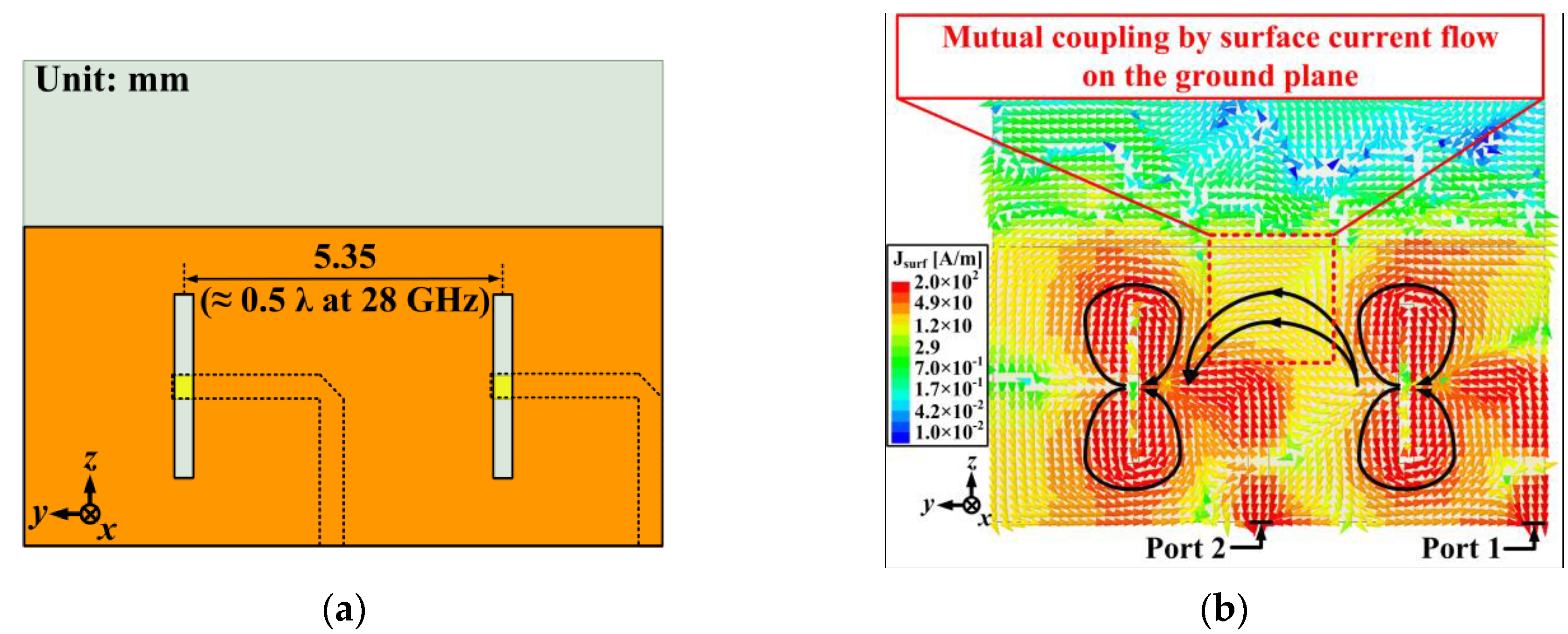
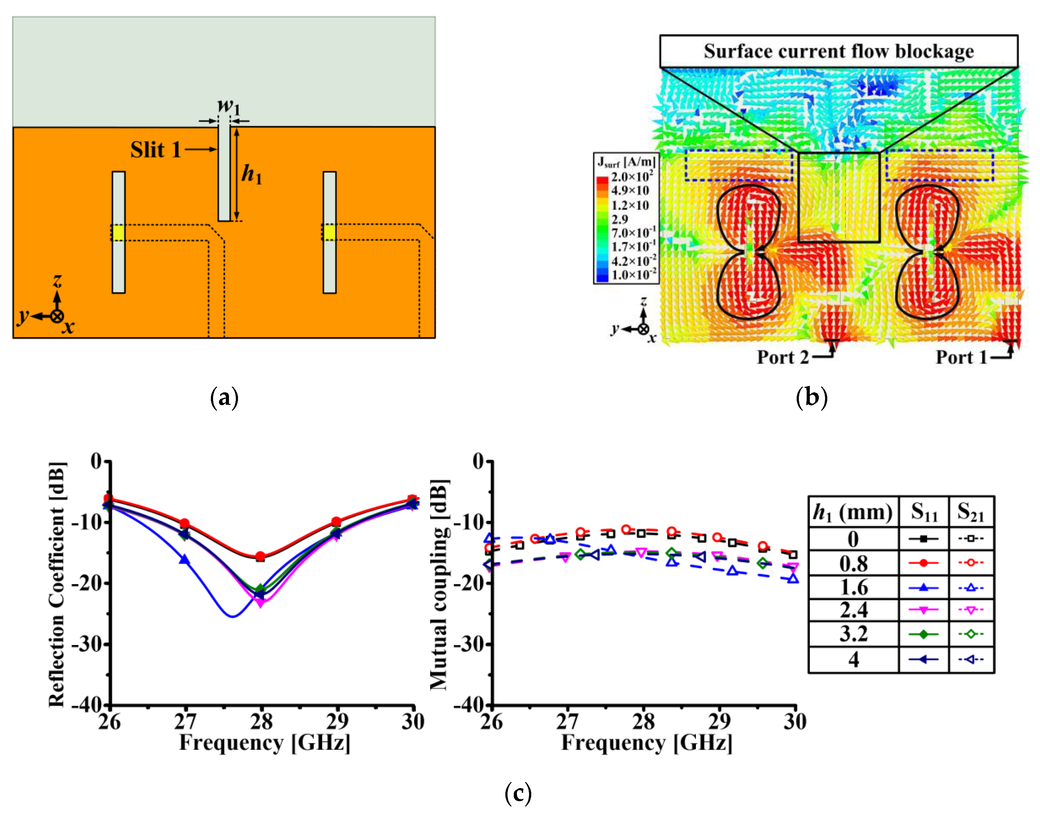
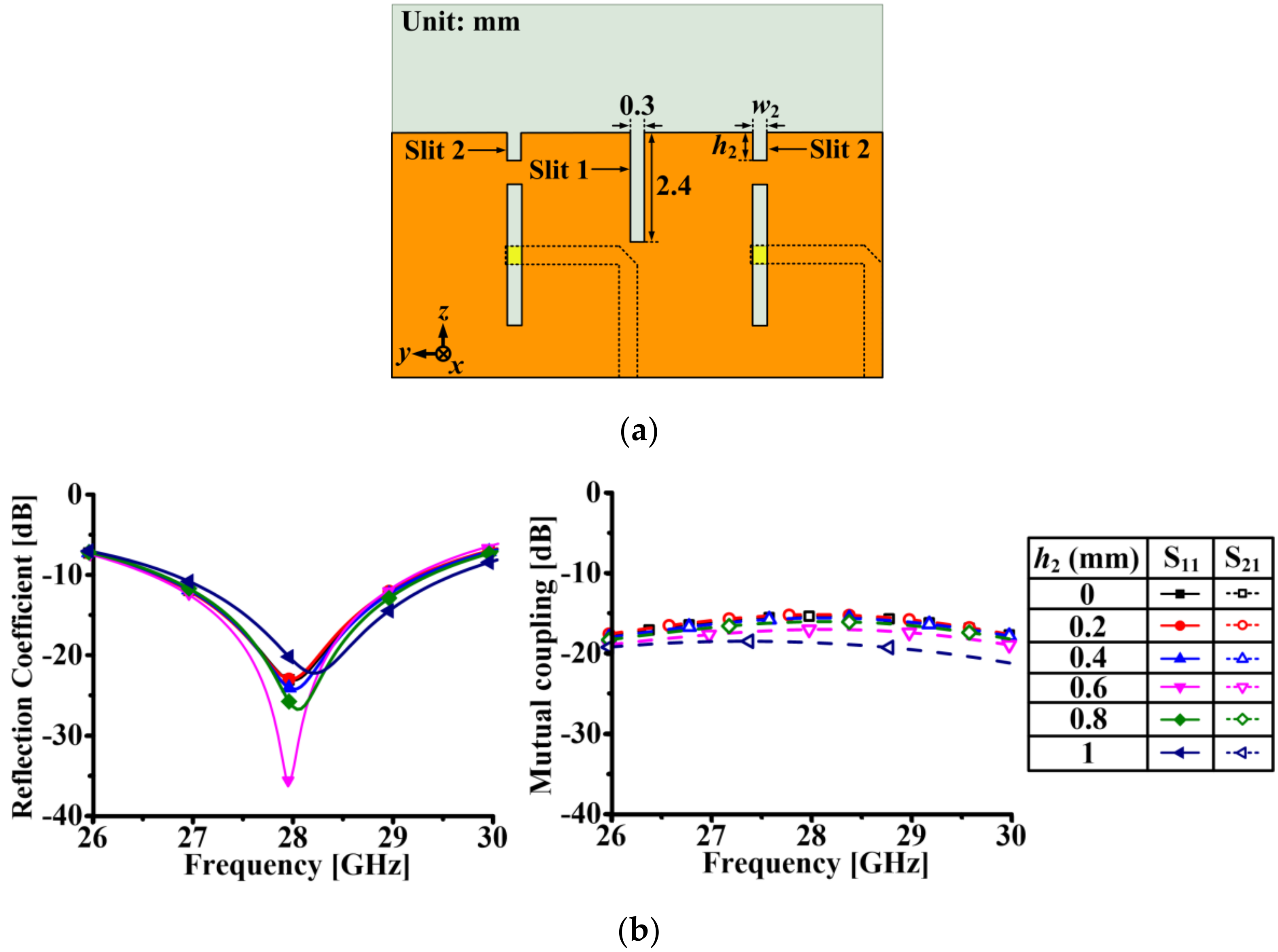
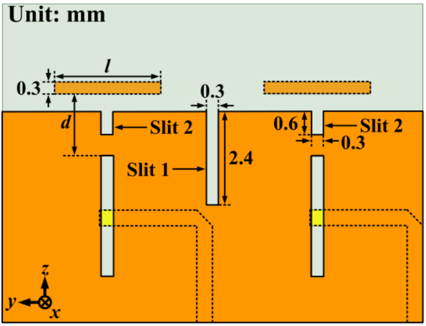
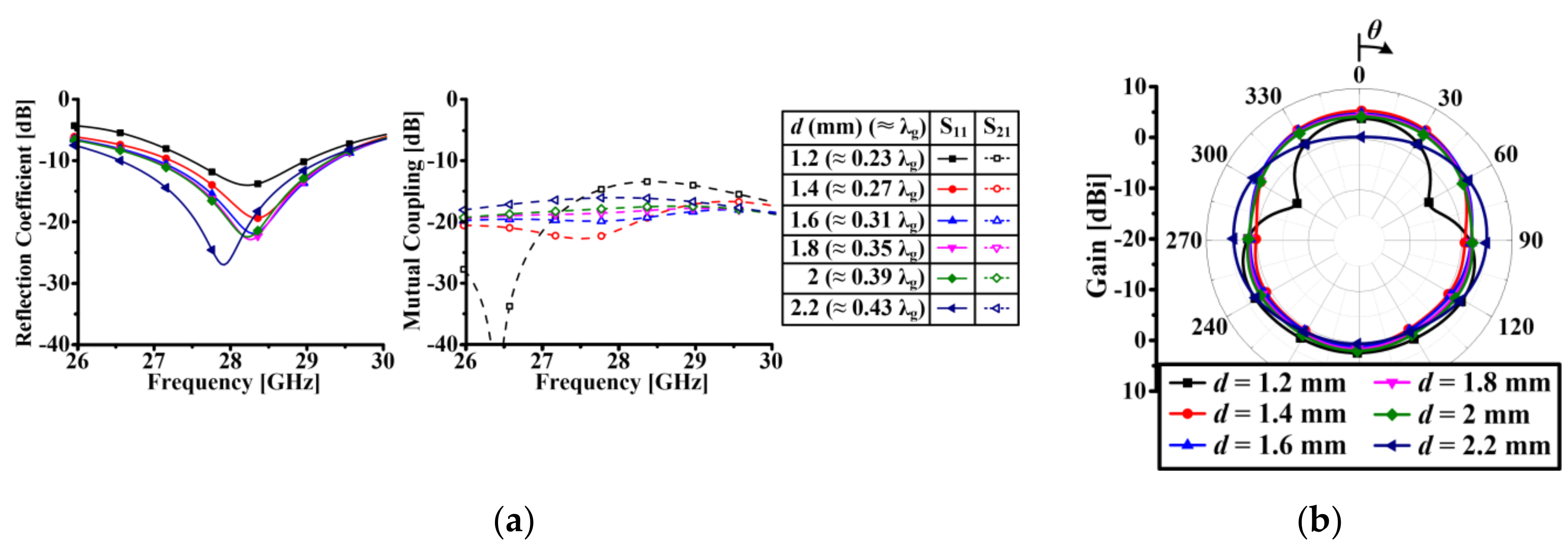
2.2. 1 × 2 Array Antenna Design and Performance

For designing antenna arrays, mutual coupling between radiators should be considered for good antenna performance. As shown in Figure 3a, we designed a 1 × 2 array antenna composed of basic slot radiators to investigate mutual coupling (S21) between the radiators. The center-to-center spacing is 5.35 mm (0.5 λ at 28 GHz). The surface current on the ground plane between the adjacent radiators flows from port 1 to port 2, which is indicated by a dotted red square in Figure 3b, and this current flow results in high mutual coupling.
To mitigate the effect of the surface current, as shown in Figure 4a, we inserted a slit (Slit 1) in the middle of two slots. Figure 4c shows the simulated results of S11 and S21 with various lengths of Slit 1 (h1). In this case, the width of Slit 1 (w1) is the same as the width of the slot radiator (w1 = 0.3 mm). The best performance of S11 at 28 GHz is achieved when h1 is 2.4 mm. Without Slit 1 (h1 = 0 mm), the simulated S21 is lower than −11.96 dB over the target band. However, when h1 becomes longer than 2.4 mm, S21 converges to below −15 dB over the target band. Figure 4d shows the simulated results of S11 and S21 with various w1. In this case, h1 is fixed at 2.4 mm. The best performance of S11 is achieved when w1 is 0.3 mm, and the variation of w1 has little effect on the performance of S21.
Therefore, we considered that the optimized dimension of Slit 1 is 2.4 × 0.3 mm. As a result, by inserting the optimized Slit 1, most of the surface current on the ground plane between the radiators is blocked, which is indicated by the solid black square in Figure 4b.
As shown in Figure 5a, we inserted another slit (Slit 2), maintaining Slit 1, to enhance the impedance matching by disturbing the surface current concentrated at the edge of the ground plane, which is indicated by the dotted blue rectangles in Figure 4b. In addition, inserting Slit 2 contributes to reduce the mutual coupling when the directors are added. This will be discussed in a later paragraph. Figure 5b shows the simulated results of S11 and S21 with various lengths of Slit 2 (h2). In this case, the width of Slit 2 (w2) is the same as the width of Slit 1 (w2 = 0.3 mm). The best impedance matching at 28 GHz is achieved when h2 is 0.6 mm. Figure 5c shows the simulated results of S11 and S21 with various values of w2. In this case, h2 is fixed at 0.6 mm. The best performance of S11 is achieved when w2 is wider than 0.2 mm, and the performances of S21 are almost same regardless of the variation of w2. Therefore, we considered that the optimized dimension of Slit 2 is 0.6 × 0.3 mm.
As shown in Figure 6, directors are added to the 1 × 2 array antenna with optimized slits to reinforce the radiated field toward the director. Figure 7a shows the simulated results of S11 and S21 with various distances between slot aperture and the director (d). In this case, the length of the director (l) is fixed at 2.7 mm (≈0.52 λg). When d is 1.6 mm (≈0.31 λg), although the S11 performance is not the best, the S21 performance is the most stable in the target band. The simulated S21 is lower than −19 dB over the target band when d is 1.6 mm. Also, the simulated radiation pattern with d of 1.6 mm is stable, as shown in Figure 7b. If the distance is too close or too far, such as d is 1.2 mm (≈0.23 λg) or 2.2 mm (≈0.43 λg), the radiation pattern deteriorates.
The length (l) of the director is also an important factor for the quasi-Yagi antenna. Figure 8a shows the simulated results of S11 and S21 with various l. In this case, d is fixed at 1.6 mm. When l is 2.7 mm (≈0.52 λg), the S21 performance is the most stable in the target band. Also, the simulated radiation pattern with l of 2.7 mm is stable, as shown in Figure 8b. If l is longer than 2.7 mm, the radiation pattern deteriorates. Therefore, we considered that the optimized length and distance of director are 2.7 and 1.6 mm, respectively.
The effects of the slits on the mutual coupling and radiation performance become more apparent when considered together with the director. The surface current flows from port 1 to port 2 in a 1 × 2 array antenna without slits as shown in Figure 9b. The surface current is concentrated at the edge of the ground plane, which is indicated by a dotted red circle in Figure 9b.
To mitigate the effect of the surface current, as shown in Figure 10a, we inserted an optimized slit (Slit 1) at that position. By inserting Slit 1, most of the surface current on the ground plane between the radiators is blocked, which is indicated by the solid black square in Figure 10b. However, the flow of the surface current on the substrate between adjacent directors still exists, and this current contributes to increase the mutual coupling. Electromagnetic coupling occurs between the directors and the surface current concentrated at the edge of the ground plane, which is indicated by the solid blue square in Figure 10b, thereby generating mutual coupling between electromagnetic waves propagating in the +z direction. This mutual coupling between the propagating electromagnetic waves is described as the surface current on the substrate, which is indicated as a dotted red circle in Figure 10b. Therefore, we inserted optimized slits (Slit 2) on the edge of the ground plane to disturb the flow of the surface current, as shown in Figure 11a,b. The mutual coupling on the substrate between the directors is reduced due to the weakened electromagnetic coupling by disturbing the flow of the surface current at the edge of the ground plane. The mutual coupling reduction can be shown by the simulated E-field distribution in the E-plane (xy plane) at 28 GHz. As shown in Figure 9c, without the slits, the mutual coupling is mainly due to the propagation of the surface wave along the y direction from port 1 to port 2. By inserting only Slit 1, the surface wave propagation between the radiators is suppressed, as shown in Figure 10c. In Figure 11c, the surface wave propagation is further suppressed by inserting both Slit 1 and Slit 2. Figure 12a shows the simulated S11 and S21 of the 1 × 2 array antenna with directors considering the slits. The simulated −10 dB S11 of all the cases cover the target band. The simulated S21 of the antenna without the slits is lower than −11.85 dB over the target band. However, the simulated S21 of the antenna with only Slit 1 is lower than −15.91 dB over the target band. In the case of the antenna with both Slit 1 and Slit 2, the simulated S21 is lower than −19 dB over the target band. Figure 12b shows the simulated radiation patterns of the antenna with and without the slits. The simulated gains of the antenna without slits, with only Slit 1, and with both Slit 1 and Slit 2 in the +z direction are 1.12, 2.48 and 5.02 dBi, respectively. However, the gains in the −z direction in all cases remain almost the same, around 0.98 dBi. Therefore, the slits contribute to reduce the mutual coupling and enhance the radiation performance.

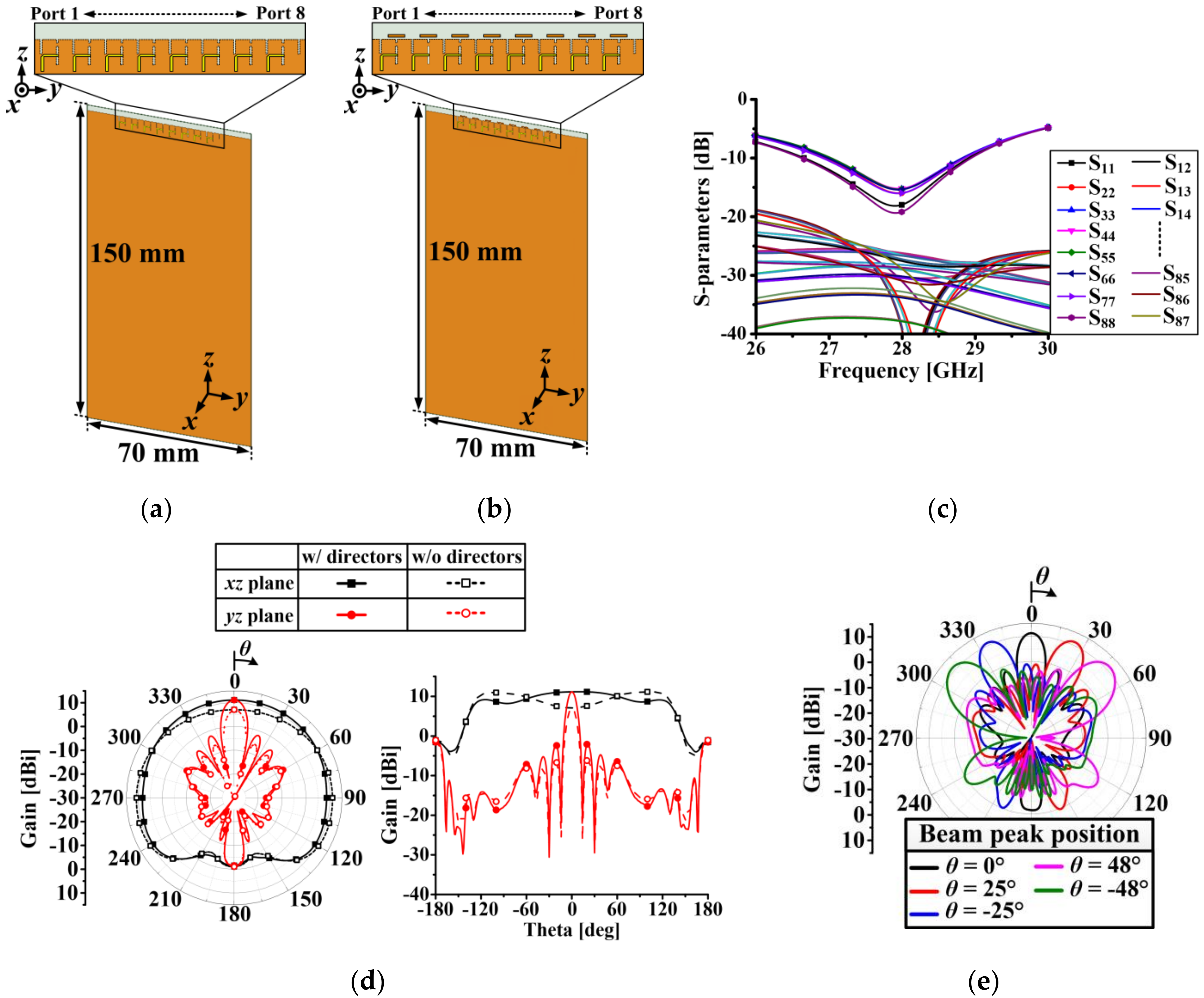
2.3. 1 × 8 Array Antenna Design and Performance

Figure 13 shows the structures and simulated results of the 1 × 8 array antenna with and without directors. The array antenna is located at the top side of the ground plane with dimensions of 150 × 70 mm, to verify the antenna performance on a typical mobile terminal. The substrate material and detailed antenna structures are identical to those of the single and 1 × 2 array cases, except for the size of the ground plane. Figure 13c shows the simulated S-parameters of the array antenna with the directors in free space. The simulated −10 dB reflection coefficients (S11–S88) cover the frequency band from 27.03 to 28.82 GHz. The proposed antenna has a low mutual coupling characteristic of lower than −25.02 dB within the target band due to the inserted slits. The simulated radiation patterns at 28 GHz are illustrated in Figure 13d. The simulated peak gain of the antenna without the directors is formed around from −90° to −120° and from +90° to +120° in the xz plane since the electromagnetic wave is radiated perpendicular to the slotted aperture. Therefore, the directors are added to compensate for the reduced gain in the +z direction. The simulated gains of the array antenna with and without the directors in the +z direction are 11.16 and 7.09 dBi, respectively. The proposed array antenna with the directors has a very wide HPBW of 256.72° in the xz plane and a side-lobe level (SLL) of −13.06 dB in the yz plane. The simulated front-to-back ratio (FBR) of the array antenna with the directors is 12.71 dB. Figure 13e shows the simulated beam steering performance of the 1 × 8 array antenna with the directors in the yz plane. At 28 GHz, the proposed array antenna covers up to ±48° by using the linear phase progression with uniform amplitude between elements. The reference to define the maximum beam steering angle is the SLL of −10 dB [15]. In this range, all of the simulated peak gains are higher than 11.09 dBi.

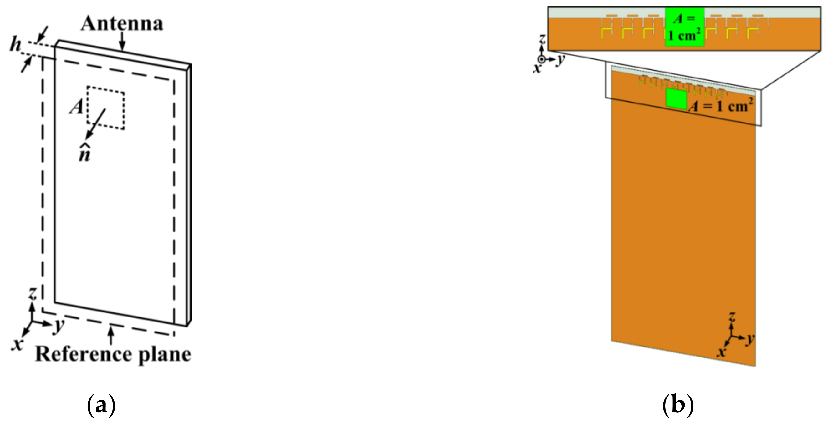
2.4. Analysis of Human Body Effect

At mm-wave frequencies, since most of the energy is absorbed within a short distance from the skin, the power density is used as a basic restriction in RF exposure to the human body, instead of the specific absorption rate (SAR) [16]. Currently, the World Health Organization (WHO) recommends a standard established by the International Commission on Non-Ionizing Radiation Protection (ICNIRP). In addition, South Korea adopted the WHO recommended standard [17]. Therefore, in this paper, the RF exposure standard established by the ICNIRP was used [18]. According to the standard, in 10–300 GHz frequency band, the spatial power density averaged over any 1 and 20 cm2 on the reference plane shall not exceed 200 and 10 W/m2, respectively. The spatial-average power density can be calculated using the Poynting vector, as shown in Equation (1) [19,20,21]. Figure 14a shows the evaluation model of the power density. The power density is assessed over an averaging area A, which is perpendicular to the unit vector n ^ , with a separation distance h away from the antenna. As shown in Figure 14b, the power density of the proposed 1 × 8 array antenna is simulated with A = 1 cm2 and h = 10 mm by using the Fields Calculator of the HFSS software [22]. Assuming that the mobile terminal is located at a distance of 10 mm away from the head in talk mode, the separation distance h was determined to be 10 mm [23]. The simulated spatial-average power density of the proposed array antenna is 138.53 W/m2 with 20 dBm input power at each lumped port [19].
S = 1 2 A A R e [ E × H   ] · n ^ d A   [ W / m 2 ]
To investigate the impacts of the human body on the antenna performance at 28 GHz, S-parameters and radiation patterns of the proposed 1 × 8 array antenna with a simplified skin phantom were simulated as in Figure 15. As we mentioned, since skin penetration depth of the energy is less than 2 mm at 15 GHz and less than 1 mm at 30 GHz [16], a simplified skin phantom of 2 mm thickness with a relative dielectric constant of 16.6 and conductivity of 25.8 S/m at 28 GHz was used [24]. Since a full human body phantom model is very time-consuming to analyze in the simulation software, a simplified skin layer was introduced. The dimensions of the phantom are 28 × 70 mm and this size is enough to cover the radiators. As shown in Figure 15a, the simulations were performed using a simplified skin phantom spaced vertically from the antenna with the gap distance of g. A slot antenna is complementary to a planar electric dipole and is called a magnetic-type antenna since the electric source J on the planar electric dipole is replaced by the magnetic source M on the slot antenna by Babinet’s principle [25]. In Equation (2), Z is the intrinsic impedance of the surrounding medium (air), and Z1 and Z2 are the input impedances of the two complementary antennas (slot and planar electric dipole), respectively. The slot antenna has a constant impedance of 60π Ω (in air) that is independent of frequency since Z1 is equal to Z2 for ideal complimentary structures [12,13]. In other words, when the slot antenna operates in free space, the variation of the input impedance of the slot antenna is less sensitive even if an object is present around the antenna. Simulated S-parameters when g = 5, 10, and 20 mm are shown in Figure 15c–e. The simulated reflection coefficients of all cases fully cover the target band. However, the mutual coupling levels are slightly degraded due to the existence of the skin phantom. In free space, the mutual coupling is lower than −25.02 dB within the target band, but when there was a phantom, it became lower than −21.02 dB when g = 5 mm. The important point is that even though the phantom is present around the proposed antenna, it still has a low mutual coupling characteristic of lower than −20 dB. Figure 15b shows the simulated radiation patterns in the xz plane for various g values. As the phantom approaches closer to the antenna, the radiation pattern in the direction of the phantom (+x direction; θ = 90°) is deteriorated compared to the case without the phantom. However, the radiation performance of the other parts remains almost the same. Therefore, it is considered that the radiation performance of the magnetic-type antenna is less sensitive to the presence of the human body compared to electric-type antennas.
Z 1 Z 2   = Z 2 / 4

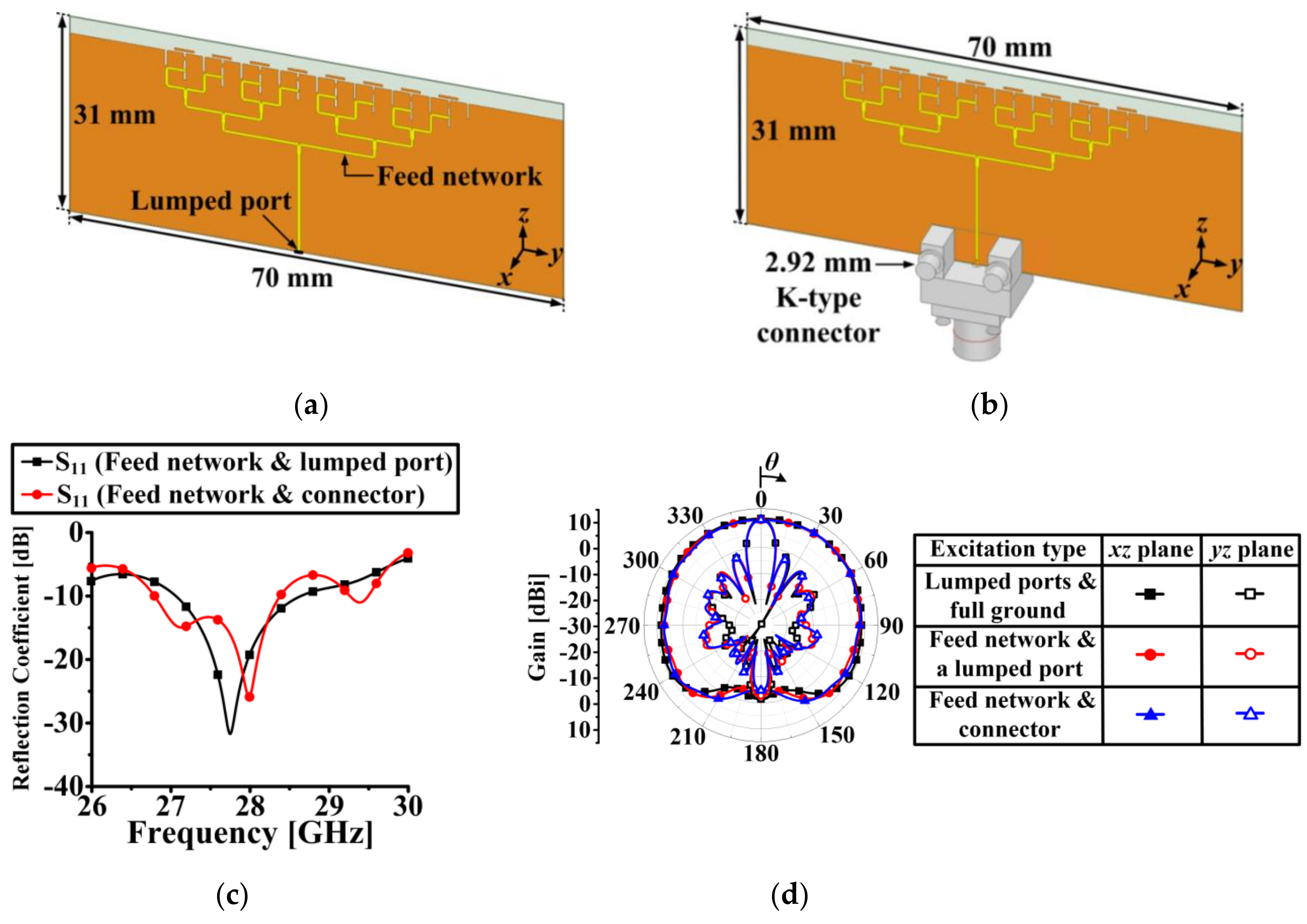
2.5. Effect of an RF Connector and a Feeding Network

To investigate the effects of an RF connector and a feeding network on the antenna performance in actual antenna fabrication and measurement, simulations using the connector model and the feeding network should be carried out. Since the connector is an electrically large structure at 28 GHz, the full ground plane with the dimensions of 150 × 70 mm with the feeding network and the connector is very time-consuming to analyze using the simulation software. Therefore, as shown in Figure 16a,b, a modified ground plane with the dimensions of 31 × 70 mm was considered. The connector model was based on the datasheet for a 2.92 mm end-launch connector [26]. The only difference between Figure 16a,b is an excitation type. As shown in Figure 16a, the proposed array antenna was excited by the feeding network and a lumped port is located at the end of the feeding network. However, as shown in Figure 16b, the lumped port at the end of the feeding network was substituted by the connector. Figure 16c,d shows comparisons of simulated S11 values and radiation patterns for two different excitation types. The simulated −10 dB S11 bandwidth of the proposed array antenna with the feeding network and the lumped port excitation is 1.58 GHz (27.06–28.64 GHz). The simulated −10 dB S11 bandwidth of the proposed array antenna with the feeding network and the connector excitation is 1.59 GHz (26.79–28.38 GHz). Therefore, the proposed antenna covers the target band regardless of the excitation type. The simulated radiation patterns according to the excitation types are similar to each other, as shown in Figure 16d. In addition, the modified ground plane size has little effect on the antenna radiation performance.

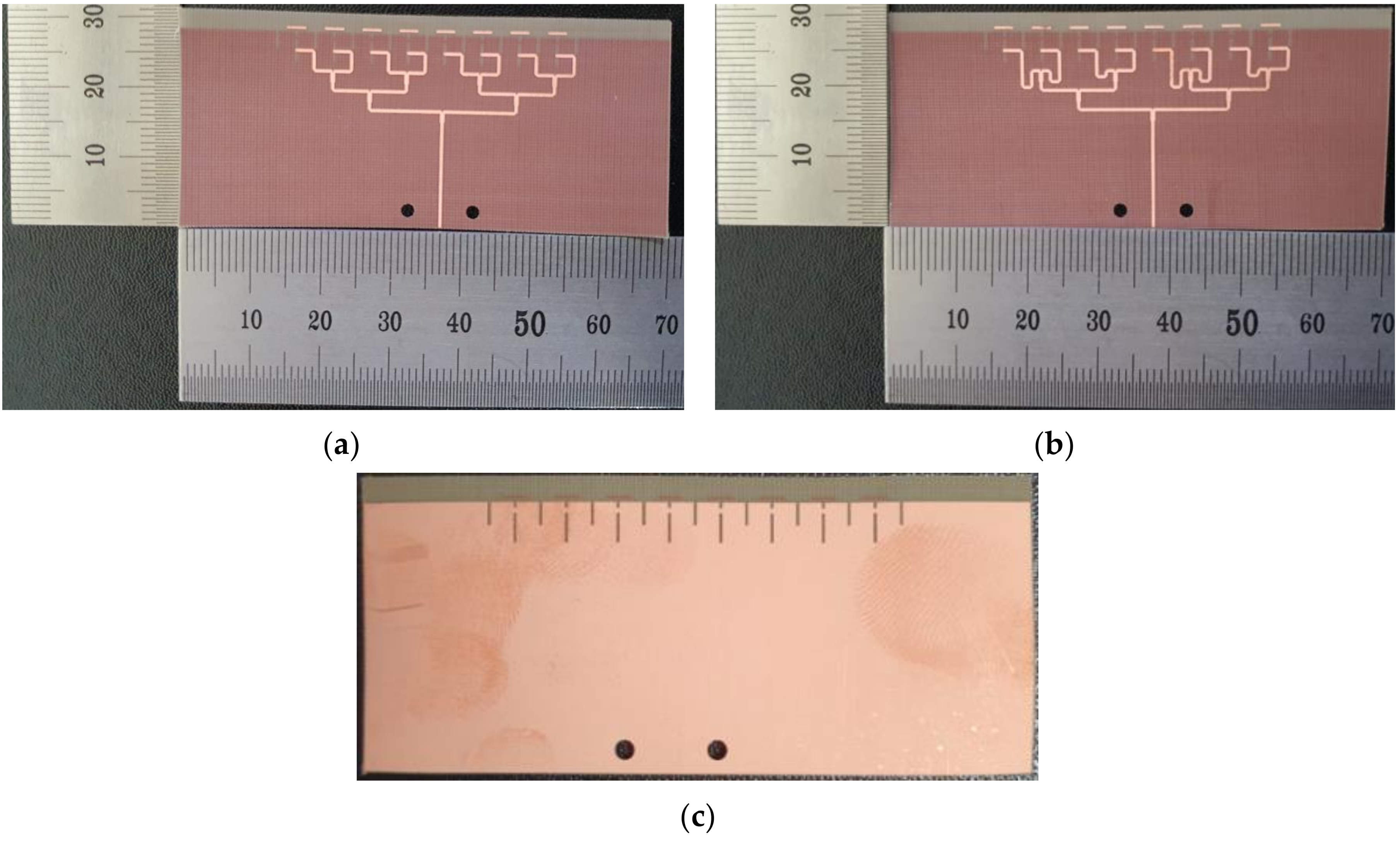
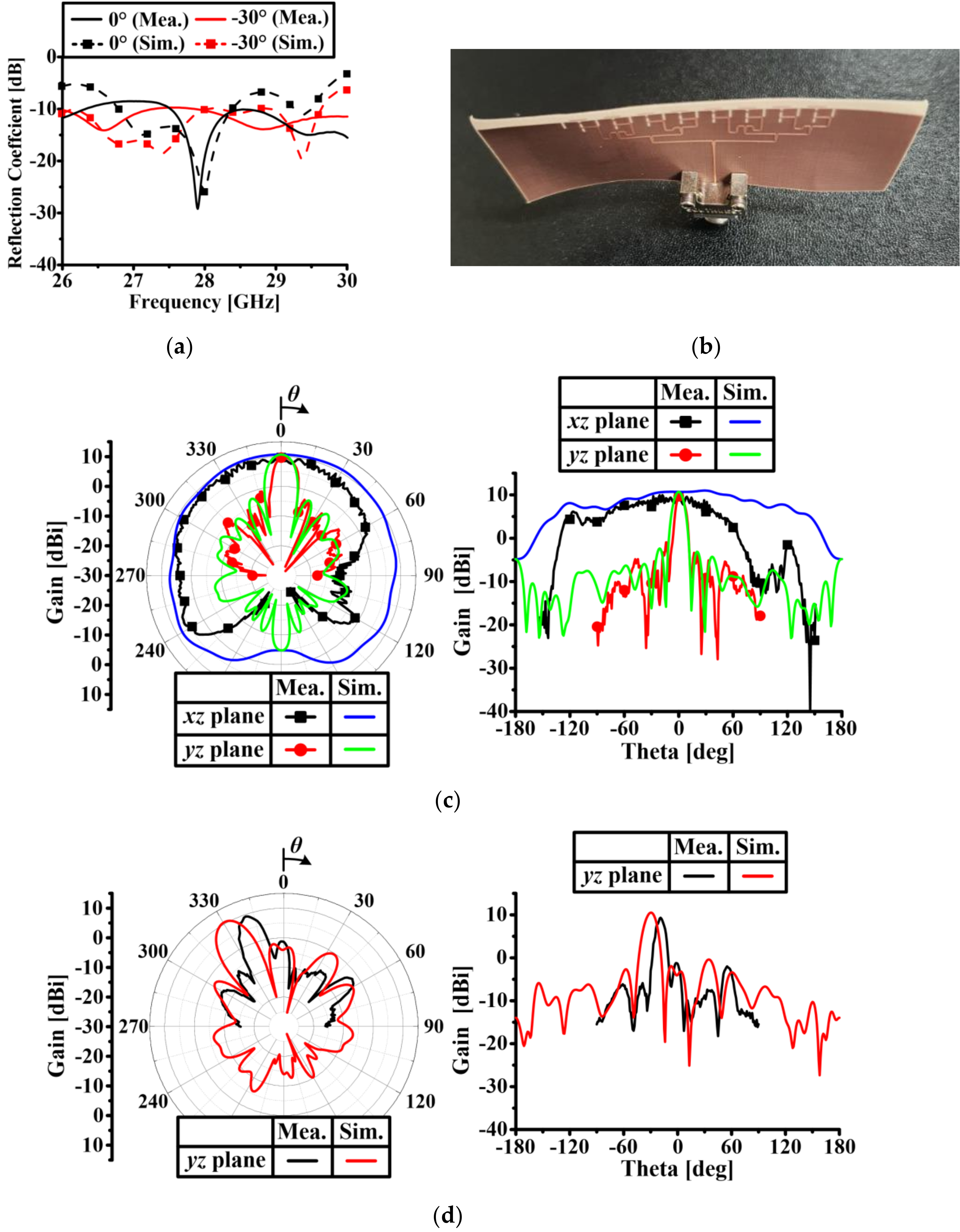
3. Experimental Results

Figure 17 shows the fabricated prototypes of the proposed 1 × 8 array antenna. Figure 17a shows a fabricated array antenna with a 0° beam steering angle. Figure 17b shows a fabricated antenna with a fixed beam steering angle. Fixed microstrip line delays in the feeding network are employed to achieve a beam steering angle of −30°. The bottom sides of each case are the same as shown in Figure 17c.
The measurement setup in an anechoic chamber is shown in Figure 18a. The proposed antenna is located on the jig and it is rotating during the measurement. The measurement result is inaccurate between 90° and 270° due to the influence of the jig and other structures. Therefore, we measured the radiation patterns in the yz plane only between +90° and −90° as shown in Figure 18b. However, the radiation pattern in the xz plane was measured between +150° and −150° to verify the fan-beam performance as shown in Figure 18c.
Figure 19a shows the measured and simulated S11 with a connector and feeding networks, and there exists a reasonable agreement between the results. Discrepancies between the simulated and measurement results may be caused by fabrication errors. Figure 19c shows the measured and simulated radiation patterns at 28 GHz for a 0° beam steering angle with a connector and feeding network. The simulated and measured gains at 0° are 10.7 and 9.7 dBi, respectively. The simulated FBR is 15.5 dB and there is no measured FBR result due to the limitations in the rotating angle of measurement facility. The simulated HPBW with a connector and feeding network is 162.3° as shown in Figure 19c. However, the measured radiation pattern in the xz plane between 60° and 120° is drastically deteriorated due to the influence of the RF cable and metal structures. As shown in Figure 19c, in the case of measuring radiation patterns between 60° and 120°, the jig is rotating toward the +150° direction and the electromagnetic wave radiated from the fixed reference antenna is affected by the RF cable and metal structures which are electrically large at the 28 GHz band. However, the rest of the measured radiation pattern in the xz plane is similar to the simulated one. Figure 19d shows the simulated and measured beam steering performance at 28 GHz. In the simulation, the peak gain of 10.52 dBi is located at −30° in the yz plane with a SLL of −10.9 dB. However, the measured peak gain of 9.33 dBi is located at −19° in the yz plane with a SLL of −10.5 dB. Discrepancies between the simulated and measurement results may be caused by bending of the substrate as shown in Figure 19b. The 0.2 mm thick substrate is so thin that it is easily bent and this affects the beam steering performance significantly. However, the measured and simulated results are in good agreement except for the beam peak location.
Table 1 demonstrates the comparison on the performance of the proposed quasi-Yagi slotted array antenna and other state-of-the-art fan-beam antenna for mm-wave 5G applications. As indicated, the proposed antenna has the merit of a wider beamwidth.

4. Conclusions

In this paper, a quasi-Yagi slotted array antenna is proposed. The proposed antenna has fan-beam radiation characteristics for wide beam coverage with beam steering capability. The very wide HPBW of 256.72° with a peak gain of 11.16 dBi is achieved by a slot antenna array with directors. Low mutual coupling characteristics are achieved by inserting slits on the ground plane to suppress the flow of the surface current and surface wave. To account for the effect of the human body on the antenna performance, a simulation was conducted with a simplified skin phantom with various separation distances. The proposed antenna shows stable performance near the human phantom since the antenna is a magnetic type. The proposed antenna satisfies the RF EMF exposure limit established by ICNIRP. Therefore, the proposed 1 × 8 array antenna is a good candidate for 28 GHz 5G mobile terminal applications.

Author Contributions

The presented work was carried out in collaboration between all the authors; S.K. and J.C. supervised the research. All authors have read and agreed to the published version of the manuscript.

Funding

This work was supported by the Leaders in the Industry-University Cooperation+ (LINC+) program of the National Research Foundation of Korea (NRF) grant funded by the Korea government (No. 2020-A-G011-010100).

Conflicts of Interest

The authors declare no conflict of interest.

References

  1. Kim, S.; Choi, J. Array antenna with linear and circular polarization characteristics for 28 GHz band 5G mobile handset applications. J. Korean Inst. Electromagn. Eng. Sci. 2020, 31, 33–42. [Google Scholar] [CrossRef]
  2. Bang, J.; Choi, J. A SAR reduced mm-wave beam-steerable array antenna with dual-mode operation for fully metal-covered 5G cellular handsets. IEEE Antennas Wirel. Propag. Lett. 2018, 17, 1118–1122. [Google Scholar] [CrossRef]
  3. Lee, H.; Kim, S.; Choi, J. A 28 GHz 5G phased array antenna with air-hole slots for beam width enhancement. Appl. Sci. 2019, 9, 4204. [Google Scholar] [CrossRef] [Green Version]
  4. Zhang, J.; Ge, X.; Li, Q.; Guizani, M.; Zhang, Y. 5G millimeter-wave antenna array: Design and challenges. IEEE Wirel. Commun. 2016, 24, 106–112. [Google Scholar] [CrossRef]
  5. Sulyman, A.I.; Nassar, A.T.; Samimi, M.K.; MacCartney, G.R., Jr.; Rappaport, T.S.; Alsanie, A. Radio propagation path loss models for 5G cellular networks in the 28 GHz and 38 GHz millimeter-wave bands. IEEE Commun. Mag. 2014, 52, 78–86. [Google Scholar] [CrossRef]
  6. Roh, W.; Seol, J.; Park, J.; Lee, B.; Lee, J.; Kim, Y.; Cho, J.; Cheun, K. Millimeter-wave beamforming as an enabling technology for 5G cellular communications: Theoretical feasibility and prototype results. IEEE Commun. Mag. 2014, 52, 106–113. [Google Scholar] [CrossRef]
  7. El-Halwagy, W.; Mirzavand, R.; Melzer, J.; Hossain, M.; Mousavi, P. Fence shaping of substrate integrated fan-beam electric dipole for high-band 5G. Appl. Sci. 2019, 8, 545. [Google Scholar] [CrossRef] [Green Version]
  8. Zhou, H.; Aryanfar, F. Millimeter-wave open ended SIW antenna with wide beam coverage. In Proceedings of the 2013 IEEE Antennas and Propagation Society International Symposium, Orlando, FL, USA, 7–13 July 2013; pp. 1–2. [Google Scholar]
  9. Hong, W.; Beak, K.; Lee, Y.; Kim, Y.G. Design and analysis of a low-profile 28 GHz beam steering antenna solution for future 5G cellular applications. In Proceedings of the 2014 IEEE MTT-S International Microwave Symposium, Tampa, FL, USA, 1–6 June 2014; pp. 1–4. [Google Scholar]
  10. Bang, J.; Choi, J. A compact hemispherical beam-coverage phased array antenna unit for 5G mm-wave applications. IEEE Access 2020, 8, 139715–139726. [Google Scholar] [CrossRef]
  11. Lee, W.-W.; Hwang, I.-J.; Jang, B. End-fire Vivaldi antenna array with wide fan-beam for 5G mobile handsets. IEEE Access 2020, 8, 118299–118304. [Google Scholar] [CrossRef]
  12. Mäkinen, R.M.; Kellomäki, T. Body effects on thin single-layer slot, self-complementary, and wire antennas. IEEE Trans. Antennas Propag. 2014, 62, 385–392. [Google Scholar] [CrossRef]
  13. Booker, H.G. Slot aerials and their relation to complementary wire aerials (Babinet’s principle). J. IET Part ⅢA Radiol. 1946, 93, 620–626. [Google Scholar] [CrossRef]
  14. 5G Americas. Spectrum above 24 GHz. In 5G Americas White Paper—5G Spectrum Vision; 5G Americas: Washington, WA, USA, 2019; pp. 8–9. [Google Scholar]
  15. Khalily, M.; Tafazolli, R.; Rahman, T.A.; Kamarudin, M.R. Design of phased arrays of series-fed patch antennas with reduced number of the controllers for 28-GHz mm-wave applications. IEEE Antennas Wirel. Propag. Lett. 2016, 15, 1305–1308. [Google Scholar] [CrossRef] [Green Version]
  16. Wu, T.; Rappaport, T.S.; Collins, C.M. Safe for generations to come: Considerations of safety for millimeter waves in wireless communications. IEEE Microw. Mag. 2015, 16, 65–84. [Google Scholar] [CrossRef] [PubMed] [Green Version]
  17. Choi, H.D.; Kim, N. 5G electromagnetic waves and analysis of impacts of EMF exposure. Proc. Korea Electromag. Eng. Soc. 2018, 29, 26–30. [Google Scholar]
  18. ICNIRP. Guidelines for limiting exposure to time-varying electric, magnetic, and electromagnetic fields (up to 300 GHz). Health Phys. 1998, 74, 494–522. [Google Scholar]
  19. Xu, B.; Zhao, K.; Ying, Z.; Sjoberg, D.; He, W.; He, S. Analysis of impacts of expected RF EMF exposure restrictions on peak EIRP of 5G user equipment at 28 GHz and 39 GHz bands. IEEE Access 2019, 7, 20996–21005. [Google Scholar] [CrossRef]
  20. Rodriguez-Cano, R.; Zhang, S.; Zhao, K.; Pedersen, G.F. User body interaction of 5G switchable antenna system for mobile terminals at 28 GHz. In Proceedings of the 2019 13th European Conference on Antennas and Propagation, Krakow, Poland, 1–4 March 2019. [Google Scholar]
  21. Xu, B.; Gustafsson, M.; Shi, S.; Zhao, K.; Ying, Z.; He, S. Radio frequency exposure compliance of multiple antennas for cellular equipment based on semidefinite relaxation. IEEE Trans. Electromagn. Compat. 2019, 61, 327–336. [Google Scholar] [CrossRef]
  22. Ansys. Available online: www.ansys.com/products/electonics/ansys-hfss (accessed on 4 September 2020).
  23. Yazdandoost, K.Y.; Laakso, I. EMF exposure analysis for a compact multi-band 5G antenna. Prog. Electromagn. Res. 2018, 68, 193–201. [Google Scholar] [CrossRef] [Green Version]
  24. Xu, B.; Ying, Z.; Scialacqua, L.; Scannavini, A.; Foged, L.J.; Bolin, T.; Zhao, K.; He, S.; Gustafsson, M. Radiation performance analysis of 28 GHz antennas integrated in 5G mobile terminal housing. IEEE Access 2018, 6, 48088–48101. [Google Scholar] [CrossRef]
  25. Balanis, C.A. Antenna Theory Analysis and Design, 3rd ed.; John Wiley & Sons Inc.: New York, NY, USA, 2005; pp. 697–701. [Google Scholar]
  26. Southwest Microwave. Available online: https://mpd.southwestmicrowave.com/product/1092-03a-6-end-launch-2-92mm-k-40-ghz-jack-female-standard-block/ (accessed on 4 September 2020).
Figure 1. Fan-beam radiation pattern and hemispheric beam coverage: (a) fan-beam radiation pattern, and (b) hemispheric beam coverage required in 5G mobile terminals.
Applsci 10 07686 g001
Figure 2. Single slot radiator: (a) without a director, (b) with a director, (c) side view, (d) simulated reflection coefficients, and (e) simulated radiation patterns at 28 GHz.
Applsci 10 07686 g002
Figure 3. A 1 × 2 array antenna without directors: (a) top view, and (b) simulated surface current distribution at 28 GHz.
Applsci 10 07686 g003
Figure 4. Parameter studies of the dimension of Slit 1: (a) antenna structure with Slit 1, (b) simulated surface current distribution at 28 GHz (when h1 = 2.4 mm and w1 = 0.3 mm), (c) simulated results of the reflection coefficient and mutual coupling with various lengths (h1) of Slit 1 (w1 is fixed at 0.3 mm), and (d) simulated results of the reflection coefficient and mutual coupling with various widths (w1) of Slit 1 (h1 is fixed at 2.4 mm).
Applsci 10 07686 g004aApplsci 10 07686 g004b
Figure 5. Parameter studies of the dimension of Slit 2 (dimension of Slit 1 is fixed): (a) antenna structure with Slit 1 and Slit 2, (b) simulated results of the reflection coefficient and mutual coupling with various lengths (h2) of Slit 2 (w2 is fixed at 0.3 mm), and (c) simulated results of the reflection coefficient and mutual coupling with various widths (w2) of Slit 2 (h2 is fixed at 0.6 mm).
Applsci 10 07686 g005aApplsci 10 07686 g005b
Figure 6. The 1 × 2 array antenna with directors and optimized slits.
Applsci 10 07686 g006
Figure 7. Parameter studies of the distance between the slot aperture and the director (l is fixed at 2.7 mm): (a) simulated results of the reflection coefficient and mutual coupling with various distances (d), and (b) simulated radiation patterns with various distances (d) in the xz plane at 28 GHz.
Applsci 10 07686 g007
Figure 8. Parameter studies of the length of the director (d is fixed at 1.6 mm): (a) simulated results of the reflection coefficient and mutual coupling with various lengths of the director (l), and (b) simulated radiation patterns with various lengths (l) in the xz plane at 28 GHz.
Applsci 10 07686 g008
Figure 9. The 1 × 2 array antenna without slits: (a) top view, (b) simulated surface current distribution at 28 GHz, and (c) simulated E-field distribution in the E-plane at 28 GHz.
Applsci 10 07686 g009
Figure 10. The 1 × 2 array antenna with only Slit 1: (a) top view, (b) simulated surface current distribution at 28 GHz, and (c) simulated E-field distribution in the E-plane at 28 GHz.
Applsci 10 07686 g010
Figure 11. The 1 × 2 array antenna with Slit 1 and Slit 2: (a) top view, (b) simulated surface current distribution at 28 GHz, and (c) simulated E-field distribution in the E-plane at 28 GHz.
Applsci 10 07686 g011
Figure 12. Simulated performances of the 1 × 2 array antenna with directors considering slits: (a) with S-parameters, and (b) showing the radiation patterns in the xz plane at 28 GHz.
Applsci 10 07686 g012
Figure 13. The 1 × 8 array antenna: (a) without directors, (b) with directors, (c) with simulated S-parameters with directors, (d) showing simulated radiation patterns at 28 GHz, and (e) showing simulated beam steering performances in the yz plane at 28 GHz, with directors.
Applsci 10 07686 g013
Figure 14. Simulation of the power density: (a) simulation setup, and (b) power density simulation of the proposed 1 × 8 array antenna.
Applsci 10 07686 g014
Figure 15. The 1 × 8 array antenna with a simplified skin phantom: (a) simulation setup, (b) simulated radiation patterns in the xz plane for various g values at 28 GHz, (c) simulated S-parameters when g = 5 mm, (d) simulated S-parameters when g = 10 mm, and (e) simulated S-parameters when g = 20 mm.
Applsci 10 07686 g015
Figure 16. Performance comparison for different excitation types: (a) modified structure with a lumped port, (b) modified structure with a connector, (c) simulated reflection coefficients, and (d) simulated radiation patterns at 28 GHz.
Applsci 10 07686 g016
Figure 17. Photographs of fabricated antennas: (a) top side of the 1 × 8 array antenna with a 0° beam steering angle, (b) top side of the 1 × 8 array antenna with a fixed beam steering angle, and (c) bottom side of the 1 × 8 array antenna.
Applsci 10 07686 g017
Figure 18. Measurement setup: (a) measurement setup in an anechoic chamber, (b) measurement setup for the yz plane radiation pattern, and (c) measurement setup for the xz plane radiation pattern.
Applsci 10 07686 g018
Figure 19. Simulated and measured performances of the 1 × 8 array antenna: (a) simulated and measured reflection coefficients with the connector, (b) bending of the substrate, (c) radiation patterns at 28 GHz with a 0° beam steering angle, and (d) radiation patterns at 28 GHz with a fixed beam steering angle.
Applsci 10 07686 g019
Table 1. Comparison with the state-of-the-art fan-beam antennas for mm-wave 5G applications.
StructureTarget Frequency (GHz)Gain
(dBi)
HPBW
[2]1 × 8 slotted array2816.92116°
[3]1 × 8 dipole array
with air hole slots
2811.15219°
[7]4 × 1 SIW cavity array2812.6133°
[9]16 × 1 mesh grid array2810.9109°
[10]1 × 8 slotted array with
AMC reflector
2811.8142°
[11]4 × 1 Vivaldi antenna array289.46165°
This work1 × 8 quasi-Yagi slotted array2811.16256.72°
Publisher’s Note: MDPI stays neutral with regard to jurisdictional claims in published maps and institutional affiliations.

