Article

Low-Profile Spidron Fractal Dipole Antenna with a Ferrite-Loaded Artificial Magnetic Conductor for Manpack Applications

Department of Electrical and Computer Engineering, Sungkyunkwan University, Suwon 440-746, Korea
*
Author to whom correspondence should be addressed.
Appl. Sci. 2020, 10(24), 8843; https://doi.org/10.3390/app10248843
Submission received: 17 November 2020 / Revised: 6 December 2020 / Accepted: 7 December 2020 / Published: 10 December 2020

Abstract

:
In this paper, a Spidron fractal dipole antenna with a ferrite-loaded artificial magnetic conductor (AMC) is presented. By applying ferrite composed of nickel–zinc with a high permeability value, a compact AMC that operates in the broadband frequency range within the high-frequency/very-high-frequency/ultra-high-frequency (HF/VHF/UHF) bands was designed. A Spidron fractal-shaped dipole antenna with a quasi-self-complementary structure was designed and combined with a miniaturized ferrite-loaded AMC. This allowed the designed AMC-integrated dipole antenna to operate in a wide frequency band, covering the HF/VHF/UHF bands, with low-profile characteristics. A prototype of the proposed Spidron fractal dipole antenna with the AMC was manufactured and measured and found to meet low VSWR (voltage standing wave radios) specifications of <3.5 within the 20–500 MHz bandwidth range. The simulated and measured results are in good agreement. The size of the Spidron fractal dipole antenna with the AMC is 0.03 × 0.026 × 0.001 λ 3 relative to the wavelength of the lowest operating frequency. The received power of the Spidron fractal dipole antenna with the AMC was also measured when it was applied to relatively small applications, such as a manpack in this case.

1. Introduction

Communication in high-frequency (HF) bandwidths—i.e., 3–30 MHz—can be transmitted without the use of a satellite up to distances of thousands of kilometers by ionospheric reflection. Accordingly, the HF band is utilized in military operations, for communications during disasters and in rugged mountain terrain [1]. In addition to the HF band, very-high-frequency (VHF) and ultra-high-frequency (UHF) bands are also used in many applications, such as unmanned aerial vehicles (UAVs) [2]. However, due to the long wavelengths of the HF, VHF and UHF bands, the size of the antenna becomes bulky. Accordingly, various miniaturized antennas which operate in the HF, VHF and UHF bands have been studied [3,4,5,6,7,8,9,10,11,12]. Nevertheless, the sizes of these antennas remain large, along with unfavorable height measurements, complicating their use in relatively small manpacks. Therefore, in addition to additional miniaturization efforts, low-profile characteristics must also be secured in consideration of aerodynamic and mobility capabilities. As a means of designing an antenna with such characteristics, one viable technique is to apply the artificial magnetic conductor (AMC) of a periodic structure, as the properties of an AMC are similar to those of a PMC (perfect magnetic conductor), which does not exist in nature [13]. Given that the AMC has in-phase reflection characteristics within a specific frequency bandwidth, it can realize low-profile characteristics and can cause the impedance matching of the antenna to have broadband characteristics [14]. In particular, several studies have attempted to design AMCs that operate at low-frequency bands with long wavelengths compared to the frequency, such as the VHF/UHF bands [15,16,17]. In one study [15], a non-foster negative inductor was used to design an AMC that operates in the broadband range within the VHF/UHF bands. However, this AMC cannot cover the HF band and is somewhat complicated to fabricate. In another study [16], by placing an airgap between the patch and the ground plane of the unit cell, the AMC operates with broadband characteristics within the UHF band. The antenna with the designed AMC has a low-profile but cannot work on the HF band. An EBG (electromagnetic band-gap) designed by applying a ferrite material was also introduced [17]. This designed hybrid EBG has an operating frequency bandwidth ratio that exceeds 22:1 but operates at frequencies higher than 170 MHz; i.e., the VHF band.
In this letter, a low-profile, ferrite-loaded Spidron fractal dipole antenna for manpack applications is presented. First, by applying a ferrite material with a high permeability value, a compact AMC that is capable of operating within a broad frequency band within the HF/VHF/UHF bands was designed [18]. The dipole antenna integrated with the AMC has a Spidron fractal shape with a quasi-self-complementary structure. Previously, Spidron fractal geometries have been introduced in various papers [19,20]. By combining the miniaturized wideband AMC and the quasi-self-complementary dipole antenna, the proposed antenna with the designed AMC can operate in the HF/VHF/UHF bands. ANSYS high-frequency simulator (HFSS) software was used to conduct all simulations in this paper. The configurations of the designed AMC and the antenna are introduced in Section 2, and the results of the comparison between the measured and simulated results are presented in Section 3. This paper concludes in Section 4.

2. Designs for the Artificial Magnetic Conductor and Antenna

2.1. A Ferrite-Loaded Artificial Magnetic Conductor Design

The complex permeability of the MP2106-0M0 ferrite is presented in Figure 1. The complex permeability consists of the real part ( μ ) and imaginary part ( μ ). The permittivity of the MP2106-0M0 ferrite is 12. The permeability value is relatively high compared to the values of general commercial substrates in the HF, VHF and UHF bands. Due to the high permeability characteristics of the MP2106-0M0 ferrite, the unit cell structure has a high inductance value [18]. As a result, the unit cell of the AMC can be designed with a small size while operating in the HF, VHF and UHF bands.
Figure 2a depicts the geometry of the designed unit cell of the artificial magnetic conductor (AMC). The unit cell structure consists of two substrates sandwiching the ferrite material. The two substrates are Taconic RF-35 substrates with a dielectric constant of 3.5, thickness of 1.52 mm and loss tangent of 0.0018, with the ferrite material, MP2106-0M0 (Laird [21]), between them, as denoted in blue in Figure 2a. In addition to the ferrite being located between each substrate, the patch of the AMC is on the upper side of the upper substrate and the ground of the AMC is on the lower side of the lower substrate. The lengths of one side of the square unit cell structure and the patch are W = 100 mm and a = 50 mm, respectively. The total thickness is 13.04 mm, which is the sum of the thicknesses of the two substrates ( S h = 1.52 mm) and the thickness of the ferrite ( F h = 10 mm). The boundary condition of the unit cell structure is illustrated in the Figure 2b. To simulate the reflection phase with a periodic boundary condition, each of the facing walls are set such that they are identical to those of a PEC (perfect electric conductor) and a PMC (perfect magnetic conductor). The waveport exists on the + z -axis, and the reflection phase on the surface of the unit cell was simulated.
Figure 3 shows the simulated reflection phase of the proposed unit cell of the AMC. The −90 –+90 operating frequency bandwidth ratio is 24:1 (19–460 MHz), covering the upper frequency ranges of the HF band, the VHF band and the lower frequency range of the UHF band. Accordingly, it can be confirmed that the unit cell, which is 0.006 × 0.006 × 0.0008 λ L 3 ( λ L is the wavelength of the lowest operating frequency) in size, operates in the HF, VHF and UHF bands given the use of the high-permeability material MP2106-0M0 ferrite.

2.2. The Proposed AMC–Combined Spidron Fractal Dipole Antenna

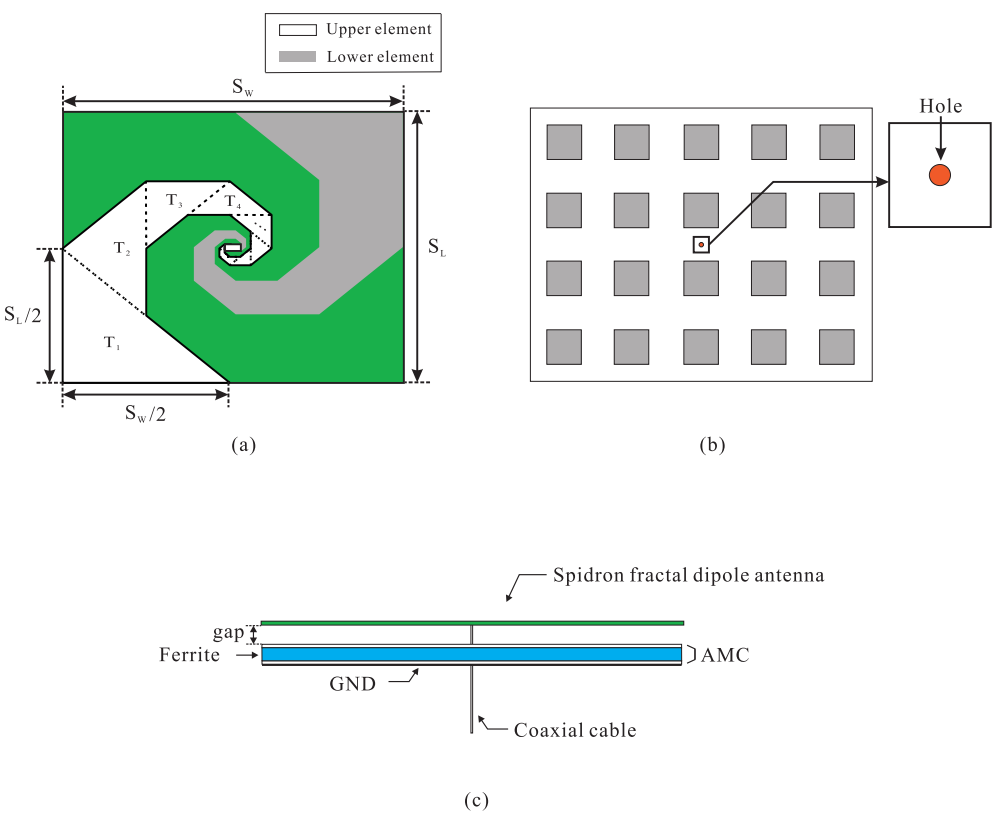
Figure 4a presents an illustration of the quasi-self-complementary Spidron fractal dipole antenna. The Spidron fractal is composed of triangles that are sequentially scaled down and added to the hypotenuse of a larger triangle [19]. To meet the specifications of a quasi-self-complementary structure, the two sides of the largest triangle are set to half of the values of S W and S L , which are 250 mm and 200 mm, respectively. The quasi-self-complementary configuration is utilized in the design of the antenna, which operates over a wide frequency bandwidth [22,23]. The Spidron fractal structure consists of 13 triangles which are scaled down with a scale factor ( δ ) of 5 2 / 8 , which is ratio of the area, T n + 1 / T n ( n = 1 , 2 , 3 . . . 12 ). The quasi-self-complementary is realized by two Spidron fractal structures on a 1.57-mm-thick Taconic RF-43 substrate (shown in green in Figure 4a), with a dielectric constant of 4.3 and a loss tangent of 0.0033 and with side lengths of S W = 500 mm and S L = 400 mm. Each side length of the substrate is set considering the size of the manpack application referred to in the literature [24]. The Spidron fractal dipole antenna elements are located symmetrically on the upper and lower sides of the substrate. The upper and lower elements are indicated in white and grey, respectively. Figure 4b shows the configuration of the AMC, which has a 4 × 5 unit cell structure. The number of unit cells and arrays of unit cells are also set considering the size of a manpack application. For the insertion of a coaxial cable, the holes shown in orange in Figure 4b with a radius of 0.85 mm were formed on the substrates and ferrite of the AMC. The quasi-self-complementary Spidron fractal dipole antenna with AMC is illustrated in Figure 4c. The distance between the Spidron fractal dipole antenna and the AMC is g a p = 1.5 mm.

3. Experimental Verification

3.1. Experimental Results of the Designed Antenna with the Standalone AMC

Based on the design parameters, the proposed antenna with the AMC was fabricated for an experimental demonstration. Figure 5a,b present top-view and side-view images of the fabricated Spidron fractal dipole antenna with the AMC. To realize a size of 500 × 400 × 10 mm 3 , four layers of 500 × 400 × 2.5 mm 3 ferrite in total were stacked and adhered using double-sided tape. The distance between the Spidron fractal dipole antenna and the AMC also included a layer of Styrofoam with a thickness of 1.5 mm.
The simulated VSWR (voltage standing wave radios) and measured VSWR are shown in Figure 6. It can be confirmed that the VSWR characteristics < 3.5 are matched at the target frequency of 20–500 MHz, and that the simulation and measured results are similar. The difference between the simulation and measurement is due to errors which arose during the manufacturing and measurement processes. Considering the performance of the commercial antenna which is utilized in manpack application [24], the VSWR characteristics of the proposed antenna are acceptable for use in the manpack application.
Figure 7 depicts the simulated radiation patterns on the y z -plane of the Spidron fractal dipole antenna with the AMC at 20 MHz, 260 MHz and 500 MHz. This figure shows that the AMC operates as a reflector and that the radiation pattern of the antenna is therefore directed onto the + z -axis. In addition, the AMC can be located at a distance of 0.0001 λ L ( λ L is the wavelength at the lowest operating frequency), which is an extremely small value compared to the value of λ / 4 ( λ is the wavelength at 20 MHz), which is the required distance between this type of antenna and a general PEC reflector. Consequently, low-profile characteristics are realized without sacrificing the performance of the antenna within a wide frequency band.
Figure 8 illustrates the realized gain on the + z -axis of the Spidron fractal dipole antenna with the AMC. The gain of the proposed antenna with the AMC varies from 33 dBi to 1.1 dBi within the operating frequency. In the high-frequency band, the proposed antenna with the AMC has a flat gain characteristic due to the characteristics of the ferrite. The gain characteristic of the commercial antenna in [24] is approximately −36 dBi at 20 MHz. Therefore, it can be confirmed that the gain characteristics of the proposed antenna are reasonable.
To verify the performance, the proposed antenna is compared with previously designed antenna [2,3,7]. The operating bandwidths and sizes of the antennas are illustrated in Table 1. It is evident that the proposed antenna has a smaller size than previous antennas. In addition, the proposed antenna has the widest operating bandwidth compared to previous studies and especially operates in HF/VHF/UHF bands. From the comparison, the proposed antenna shows good performance in terms of the operating bandwidth and a small size.

3.2. Experimental Results of the Designed Antenna with the AMC on a Manpack

Figure 9a shows a hexahedral ground plane for a manpack structure of the type worn by a person. The dimensions of the hexahedral ground plane are W × L × H (W = 500 mm, L = 400 mm and H = 200 mm) taking into account the size of the manpack application [24]. The Spidron fractal dipole antenna with the AMC on the hexahedral ground plane is shown in Figure 9b. The proposed antenna with the AMC and the hexahedral ground plane were bonded with double-sided tape. Simulated VSWRs with and without the hexagonal ground plane of the Spidron fractal dipole antenna with the AMC were compared. As shown in Figure 9c, the simulation results confirmed that the performance was not degraded regardless of whether or not the hexahedral ground plane was applied.
Figure 10a illustrates the received power measurement setup when a manpack is worn by a person. To compare the received power of the Spidron fractal dipole antenna with the AMC, a reference antenna (OMNI-A0245, ALARISANTENNAS [25]) was selected, and the power levels received on the commercial FM band (88–108 MHz) and the DMB (digital multimedia broadcasting) band (174–216 MHz) in South Korea were compared. Figure 10b depicts the measured received power levels of the Spidron fractal dipole antenna with the AMC and the reference antenna. The difference in the average reception power between the Spidron fractal dipole antenna with the AMC and the reference antenna was 8.5 dB on the FM band and 3.2 dB on the DMB band. On the FM band, where the difference in the gain characteristics between the Spidron fractal dipole antenna with the AMC and the reference antenna was large, the difference in the reception power was large, while on the DMB band, where the difference in the gain was relatively small, the difference in the reception power gain was also small. Moreover, the differences in the received power were caused by the different sizes and the different mounting positions. The power received by the antenna was analyzed by a signal analyzer (FSV signal and spectrum analyzer, Rohde & Schwarz) and the received power values in Figure 10b are shown with a 45 dB offset.

4. Conclusions

A Spidron fractal dipole antenna with a ferrite-loaded AMC is proposed in this paper. The proposed antenna operates in the HF/VHF/UHF bands with the application of a Spidron fractal shape and a broadband miniaturized AMC. By implementing MP2106-0M0 ferrite with high permeability in the AMC, the antenna can be operated in the HF/VHF/UHF bands and has a wide operating frequency bandwidth, despite its small size. The dipole antenna is designed with a quasi-self-complementary Spidron fractal structure to have broadband operating characteristics when combined with an AMC. The VSWR characteristics (<3.5) of the proposed Spidron fractal dipole antenna with the AMC satisfy the requirements of a bandwidth of 20–500 MHz. The Spidron fractal dipole antenna with the AMC has a directional radiation pattern along the + z -axis due to the influence of the AMC, with a distance between the antenna and the AMC of only 0.0001 λ L ( λ L is the wavelength at the lowest operating frequency). The size of the proposed antenna with the AMC is 0.03 × 0.026 × 0.001 λ L 3 , and the performance of the antenna with the AMC was verified by measurements. These results demonstrate that the proposed antenna with the AMC is applicable to relatively small applications that require an HF/VHF/UHF antenna with low-profile characteristics, such as a manpack.

Author Contributions

Writing, O.H.K.; Antenna design and simulation, O.H.K.; Laboratory tests, O.H.K.; Methodology, K.C.H.; Writing Review and Editing, O.H.K. and K.C.H.; Conceptualization, O.H.K. and K.C.H. All authors have read and agreed to the published version of the manuscript.

Funding

This work was supported by the National Research Foundation of Korea(NRF) grant funded by the Korea government(MSIT) (2018R1C1B6005024).

Conflicts of Interest

The authors declare no conflict of interest.

References

  1. Austin, B.A.; Liu, W.C. Assessment of vehicle-mounted antennas for NVIS applications. IEEE Proc. Microw. Antennas Propag. 2002, 149, 147–152. [Google Scholar] [CrossRef]
  2. Park, W.B.; Park, Y.; Hwang, K.C. Ferrite-loaded Spidron fractal loop VHF antenna for UAV applications. Appl. Sci. 2020, 10, 5392. [Google Scholar] [CrossRef]
  3. Chen, A.; Jiang, T.; Chen, Z.; Su, D. A novel low-profile wideband UHF antenna. Prog. Electromagn. Res. 2011, 121, 75–88. [Google Scholar] [CrossRef] [Green Version]
  4. Mattioni, L.; Marrocco, G. Design of a Broadband HF Antenna for Multimode Naval Communications—Part II: Extension to VHF/UHF Ranges. IEEE Antennas Wirel. Propag. Lett. 2007, 6, 83–85. [Google Scholar] [CrossRef]
  5. Smith, R.C.; Ignatenko, M.; Filipovic, D.S. Design of small loop antennas for on-the-move HF manpack radios. In Proceedings of the 2016 IEEE International Symposium on Antennas and Propagation (APSURSI), Fajardo, PuertoRico, 26 June–1 July 2016. [Google Scholar]
  6. Mi, S.; Lee, Y.H.; Shen, Z. Ferrite Coating Design for Near-Ground HF Bowtie Antenna. IEEE Trans. Antennas Propag. 2017, 65, 2074–2078. [Google Scholar] [CrossRef]
  7. Ren, Y. Low-profile wearable UHF antenna for portable radios and radar applications. In Proceedings of the 2011 XXXth URSI General Assembly and Scientific Symposium, Istanbul, Turkey, 13–20 August 2011. [Google Scholar]
  8. Min, K.-S. Multiband Cross-Shaped Inverse Triangular Notch Antenna for Radio Shadow Zone Communication. J. Electromagn. Eng. Sci. 2020, 20, 320–326. [Google Scholar] [CrossRef]
  9. Shin, H.; Oh, H. UHF-Band TV Transmitter for TV White Space Video Streaming Applications. J. Electromagn. Eng. Sci. 2019, 19, 227–233. [Google Scholar] [CrossRef]
  10. Lee, S.; Yoon, H.; Baik, K.-J.; Jang, B.-J. Emulator for Generating Heterogeneous Interference Signals in the Korean RFID/USN Frequency Band. J. Electromagn. Eng. Sci. 2018, 18, 254–260. [Google Scholar] [CrossRef]
  11. Ha, S.-G.; Cho, J.; Lee, J.; Min, B.-W.; Choi, J.; Jung, K.-Y. Numerical Study of Estimating the Arrival Time of UHF Signals for Partial Discharge Localization in a Power Transformer. J. Electromagn. Eng. Sci. 2018, 18, 94–100. [Google Scholar] [CrossRef]
  12. Ko, D.-O.; Woo, J.-M. Design of a Small Radio Frequency Identification Tag Antenna Using a Corrugated Meander Line Applicable to a Drug Runout Sensor System. J. Electromagn. Eng. Sci. 2018, 18, 7–12. [Google Scholar] [CrossRef]
  13. Feresidis, A.P.; Goussetis, G.; Wang, S.; Vardaxoglou, J.C. Artificial magnetic conductor surfaces and their application to low-profile high-gain planar antennas. IEEE Trans. Antennas Propag. 2005, 53, 209–215. [Google Scholar] [CrossRef] [Green Version]
  14. Foroozesh, A.; Shafai, L. Investigation Into the Application of Artificial Magnetic Conductors to Bandwidth Broadening, Gain Enhancement and Beam Shaping of Low Profile and Conventional Monopole Antenna. IEEE Trans. Antennas Propag. 2011, 59, 4–20. [Google Scholar] [CrossRef]
  15. Gregoire, D.J.; White, C.R.; Colburn, J.S. Wideband Artificial Magnetic Conductors Loaded With Non-Foster Negative Inductors. IEEE Antennas Wirel. Propag. Lett. 2011, 10, 1586–1589. [Google Scholar] [CrossRef]
  16. Mohamed-Hicho, N.M.; Antonino-Daviu, E.; Cabedo-fabres, M.; Ferrando-Bataller, M. A Novel Low-Profile High-Gain UHF Antenna Using High-Impedance Surfaces. IEEE Antennas Wirel. Propag. Lett. 2015, 14, 1014–1017. [Google Scholar] [CrossRef] [Green Version]
  17. Bell, J.M.; Iskander, M.F.; Lee, J.J. Ultrawideband Hybrid EBG/Ferrite Ground Plane for Low-Profile Array Antennas. IEEE Trans. Antennas Propag. 2007, 55, 4–12. [Google Scholar] [CrossRef]
  18. Costa, F.; Genovesi, S.; Monorchio, A. On the Bandwidth of High-Impedance Frequency Selective Surfaces. IEEE Antennas Wirel. Propag. Lett. 2009, 8, 1341–1344. [Google Scholar] [CrossRef] [Green Version]
  19. Kwon, O.H.; Park, W.B.; Lee, S.; Lee, J.M.; Park, Y.M.; Hwang, K.C. 3D-Printed Super-Wideband Spidron Fractal Cube Antenna with Laminated Copper. Appl. Sci. 2017, 7, 979. [Google Scholar] [CrossRef]
  20. Trihn-Van, S.; Thi, T.N.; Yang, Y.; Lee, K.; Jung, K.; Hwang, K.C. High-Gain Waveguide-Fed Circularly Polarized Spidron Fractal Aperture Antenna. Appl. Sci. 2019, 9, 691. [Google Scholar] [CrossRef] [Green Version]
  21. MP2106-0M0. Available online: https://www.mouser.com/datasheet/2/987/MP2106-0M0-1650723.pdf (accessed on 21 September 2020).
  22. Cortes-Mendellin, G. Non-Planar Quasi-Self-Complementary Ultra-Wideband Feed Antenna. IEEE Trans. Antennas Propag. 2011, 59, 1935–1944. [Google Scholar] [CrossRef]
  23. Gou, L.; Wang, S.; Chen, X.; Parini, C. A Small Printed Quasi-Self-Complementary Antenna for Ultrawideband Systems. IEEE Antennas Wirel. Propag. Lett. 2009, 8, 554–557. [Google Scholar]
  24. OMNI-A0167. Available online: http://www.alarisantennas.com/wp-content/uploads/2017/06/brochures/OMNI-A0167%20Version%201.5.pdf (accessed on 21 September 2020).
  25. OMNI-A0245. Available online: http://www.alarisantennas.com/wp-content/uploads/2017/06/brochures/OMNI-A0245%20Version%201.2.pdf (accessed on 21 September 2020).
Figure 1. Complex permeability of the MP2106-0M0 ferrite.
Applsci 10 08843 g001
Figure 2. Geometry of the proposed unit cell of the artificial magnetic conductor (AMC): (a) 3D view; (b) boundary condition.
Applsci 10 08843 g002
Figure 3. Simulated reflection phase of the proposed unit cell of the artificial magnetic conductor (AMC).
Applsci 10 08843 g003
Figure 4. (a) Designed Spidron fractal dipole antenna; (b) 4 × 5 AMC; (c) side view of the Spidron fractal dipole antenna with the AMC.
Applsci 10 08843 g004
Figure 5. Photographs of the fabricated Spidron fractal dipole antenna with the AMC: (a) top-view; (b) side-view.
Applsci 10 08843 g005
Figure 6. Measured and simulated VSWRs of the Spidron fractal dipole antenna with the AMC.
Applsci 10 08843 g006
Figure 7. Simulated radiation patterns of the Spidron fractal dipole antenna with the AMC on the y z -plane: (a) 20 MHz; (b) 260 MHz; (c) 500 MHz.
Applsci 10 08843 g007
Figure 8. Simulated realized gain on the + z -axis of the Spidron fractal dipole antenna with the AMC.
Applsci 10 08843 g008
Figure 9. (a) Geometry of the hexahedral ground plane; (b) photograph of the Spidron antenna with the AMC bonded onto the hexahedral ground plane; (c) simulated VSWRs of the Spidron fractal dipole antenna with the AMC with and without the hexahedral ground plane.
Applsci 10 08843 g009
Figure 10. (a) Recived power measurement setup of the manpack; (b) Measured received power levels of the Spidron fractal dipole antenna with the AMC and a reference antenna.
Applsci 10 08843 g010
Table 1. Comparison between the proposed antenna and designed antennas in previous studies (note that λ L is the wavelength corresponding to the lowest operating frequency).
DescriptionOperating BandwidthSize ( λ L 3 )
 [2]10:1 0.024 × 0.024 × 0.005
[3]1.68:1 0.72 × 0.72 × 0.07
[7]3.33:1 0.11 × 0.11 × 0.003
Proposed antenna25:1 0.033 × 0.026 × 0.001
Publisher’s Note: MDPI stays neutral with regard to jurisdictional claims in published maps and institutional affiliations.