Article

The Impact of Support Type on the Reliability of Steel Trusses Subjected to the Action of a Fire

Faculty of Civil Engineering and Architecture, Kielce University of Technology, 25-314 Kielce, Poland
*
Author to whom correspondence should be addressed.
Appl. Sci. 2020, 10(21), 7916; https://doi.org/10.3390/app10217916
Submission received: 2 October 2020 / Revised: 1 November 2020 / Accepted: 6 November 2020 / Published: 8 November 2020

Abstract

:
The objective of the article involves examining the impact of the type of supporting steel truss on its reliability under the conditions of a fire. The paper uses the system reliability method. Its application was preceded by the identification of kinematically admissible failure mechanisms (KAFMs) and the performance of strength-static calculations for all structural elements for a given moment of fire duration, meaning under the load of current temperature. The KAFMS were identified by the spectral analysis of the stiffness matrix. The criterion of the collapse for a single element was buckling for elements in compression and exceeding the yield strength for elements in tension. A reliability analysis and the calculation of temperature, axial forces, and the bearing capacity of individual elements were performed using original software created in the C++ language. The Cornell reliability index β was adopted as the measure of reliability. A drop in its value along with the fire development was presented for the analyzed structures. The obtained results indicate unambiguously that in the case of a structure subjected to fire action, the selection of a support method is of the utmost importance and determines its safety.

1. Introduction

The article discusses the issue of fire safety of steel truss structures. The objective of the publication is to check the impact of the support type of a structure on its reliability under fire conditions. It is common knowledge that the introduction of bonds that hinder the freedom of thermal deformations to structures may have disastrous results during the action of high temperature. Additional cross-sectional forces induced due to the impact of high temperature constitute a direct cause of failures of steel structures with the blockade of thermal deformations. This is what happened in the case of the Chemko-System hall in Rudna Wielka in Poland. The purlins constituted statically indeterminate beams with multiple members that were connected to main girders in a nondisplaceable manner. Such a connection resulted in considerable limitation of the displacement of purlins along the lengthwise axis, which caused the generation of considerable compressive forces, making the purlins bend and twist [1]. Scientific publications address the problem of blockade of free deformations under the conditions of elevated temperature, also from a theoretical standpoint. The article [2] analyzed two beam types: a cantilever and one fixedly mounted at both of its ends. Numerical simulations and experimental tests were performed for both types of structures under the load of temperature. In the summary, the authors point out that, when deformations are blocked, if an element is slender, it can buckle before reaching its yield point. A similar comparison is presented in article [3]. The problem of the generation of additional forces due to the impact of temperature when thermal deformations are blocked is addressed in publication [4], using the example of a stainless-steel beam.
The structures, which were considered in the paper, represent roof beams and therefore the truss model was applied. It is a simplification and it is not always so obvious that the structure works as the truss. The interesting analysis is contained in the papers [5,6], where the author analyses the truss bridges and considers what is a better solution—whether to model them as a truss or as a frame structure.
The main subject of the presented article involves the reliability of structure. Currently, it is a rapidly developing branch of science with well-established theoretical background. Numerous methods of reliability analyses can be named, including approximation methods (FORM, SORM) [7,8,9,10], simulation methods (Monte Carlo, Importance Sampling) [11,12,13,14], artificial neuron networks [15,16], as well as the system method used in this paper. For this method, one can list several classic positions of the global literature, which provide a detailed description of both the theoretical bases and more complicated issues [17,18]. In recent years, the system reliability method has been used when analyzing the safety of structures under persistent design situation [19,20,21,22]. The authors have successfully applied system analysis to the case of an accidental design situation—during a fire load [23]. So far, different methods of the reliability analysis were used in most publications in order to estimate the safety of structures under the conditions of a fire [24,25].
An unquestionable advantage of the system method is the fact that it accounts for mutual relationships between elements. Therefore, it is perfectly suitable for the analyzed aspect, where the impact of the degree of restraint of a structure on its safety is investigated under fire conditions. Unfortunately, as static indeterminacy increases, the application of this method faces a number of difficulties, related primarily to the identification of kinematically admissible failure mechanisms (KAFM). The authors have already addressed this problem in article [26], where a six-member truss is used as an example to present the method of applying the system analysis to estimate the reliability of a structure under fire conditions.

2. Methods

In the presented article, a reliability analysis was performed for steel trusses subjected to the action of fire. For this purpose, an original program created in the C++ language was used along with a computing module created in the Mathematica software (Wolfram Mathematica Software 8.0.1.0) [27,28]. The presented task was performed in two stages, with the performance of preliminary thermal-static calculations followed by the main reliability analysis. Both issues are quite vast; therefore, certain assumptions were made in order to narrow the scope of research.

2.1. Thermal-Static Analysis

Primary assumptions related to strength-static calculations are as follows:
  • the structure was analyzed in the phase of a developed fire, adopting a standard fire curve [29],
  • combustion gases have been assumed to affect each wall of the cross-section,
  • changes in the thermal properties of insulation materials were omitted; changes in the thermal and mechanical properties of steel were adopted according to the recommendations of Eurocode [30],
  • geometrical relationships were assumed to be linear,
  • it was assumed that the structure was protected against the loss of stability,
  • rheological impacts were omitted,
  • climatic loads were neglected,
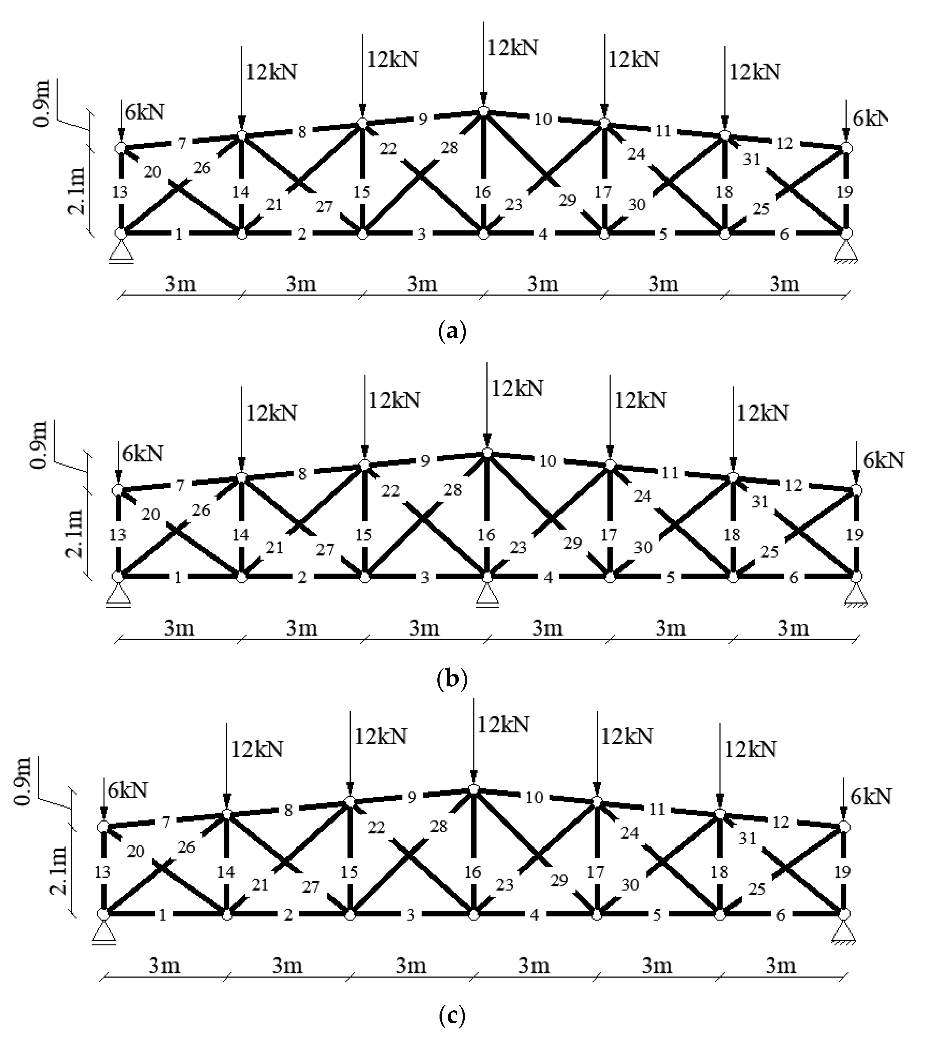
  • only permanent load (concentrated forces) and temperature act on trusses,
  • concentrated forces were applied in nodes,
  • distribution of temperature in the cross-section was considered to be constant,
  • the connections were pinned,
  • the structures were analyzed in the elastic range (the Hook’s law is valid).
The objective of a strength-static analysis involves the calculation of axial forces generated in the rods of a truss and their bearing capacity. Structures analyzed in the paper have a statically indeterminate schemes, hence subjecting them to the load of additional temperature causes a change in the distribution of axial forces. The preliminary stage of the analysis involves the determination of temperatures of individual elements during any minute of a fire duration. These temperatures are dependent on the temperature of combustion gases.
Thermal calculations were performed using the procedure described in Eurocode [30]. Apart from the temperature of combustion gases, the temperature of an element with insulation depends on the section factor, thermal properties, the density and thickness of insulation materials, as well as the density and specific heat of steel. Cross-sectional forces and displacements in a persistent design situation and in the subsequent minutes of a fire duration (taking the temperature load into account) were determined using original software utilizing the Finite Element Method (FEM). The bearing capacity of individual elements was calculated following the procedure described in the proper parts of Eurocode [30]. Because strength-static calculations under the conditions of elevated temperature have the preliminary character and are not the main part of the present paper, they will not be described any further. The procedure of their performance is known and comprehensively described in scientific papers [31,32,33].

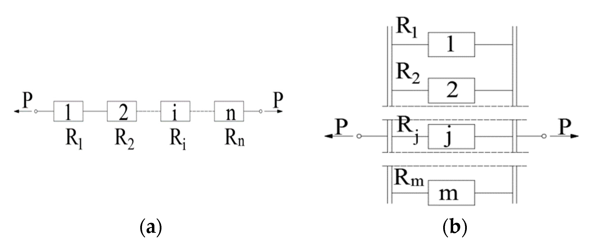
2.2. Reliability Analysis

The reliability analysis constitutes the main part of the article; therefore, the manner of its performance will be discussed in more detail. The following assumptions were made in order to simplify the issue:
  • the adopted random variables included geometrical characteristics of the cross-section area (A), mechanical properties of material (yield point fy), and the value of the effect of actions (E),
  • resistance of single elements was approximated by normal distribution,
  • random variables (x) were characterized by normal distribution with average value ( x ¯ ) and standard deviation ( σ x ),
  • randomness in the calculations of the temperature of elements and combustion gases were not taken into account,
  • it was assumed that random variables were not correlated and that they had a normal distribution,
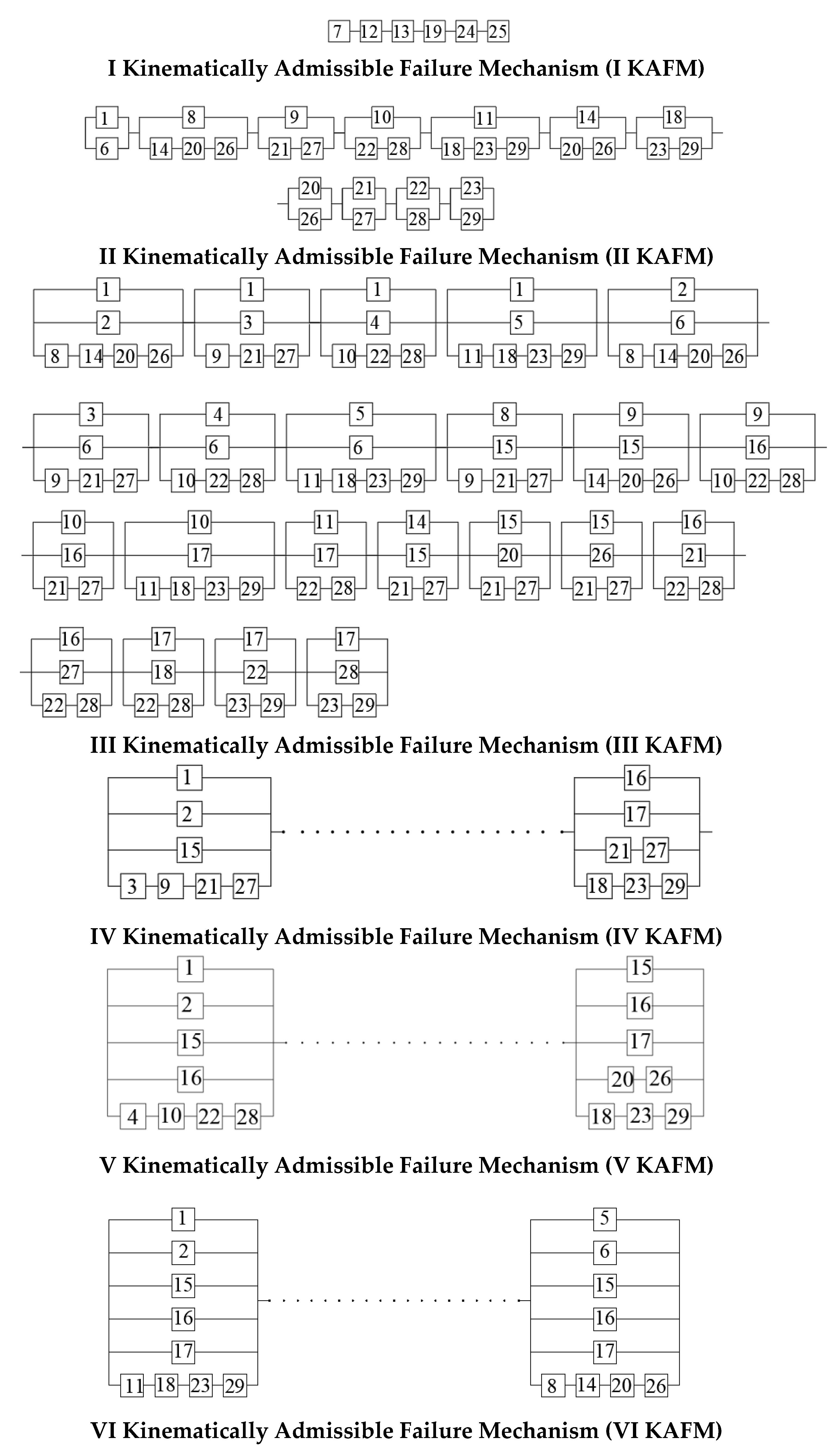
  • the single mechanisms were separated.
The paper uses the system method. It allows estimating the reliability of the entire structure based on knowledge about the reliability of individual elements (in the analyzed examples, of rods in a truss). In order to estimate the reliability of an i-th element, it is necessary to know the average value of the effect of actions ( E ¯ i ) and the average value of bearing capacity ( N ¯ i ). This should be followed by the calculation of standard deviations, i.e., σ E i and σ N i . It was assumed in the article that the respective coefficients of variation for the effect of actions is equal to νE = 0.06 [34]. A coefficient of variation for bearing capacity was appointed in the following way: the resistance of the element in compression/ tension in fire situation is defined as follows:
N b , f i / c , f i = ( χ f i ) A f y
where χ f i is the reduction factor for flexural buckling in the fire design situation. This value is bracketed because it is used only during the calculation of buckling resistance of members in compression (Nb,fi). The resistance of elements in tension in fire situation (Nc,fi) is the product of only two variables: cross-section area (A) and yield point (fy). Only these values are random (reduction factor χfi is deterministic), and according to [34], their coefficients of variation are equal to: νA = 0.06 and νfy = 0.08. The resistance coefficient of variation can be approximated as follows:
ν N = ν f y 2 + ν A 2 = 0.08 2 + 0.06 2 = 0.1
Therefore, for the i-th element:
σ E i = ν E E ¯ i = 0.06 E ¯ i
σ N i = ν N N ¯ i = 0.1 N ¯ i
Subsequently, the average values of safety margin ( Z ¯ i ) and its standard deviation ( σ Z i ) are to be calculated for each element:
Z ¯ i = N ¯ i E ¯ i
σ Z i = σ N i + σ E i
The quotient of the average value of the safety margin ( Z ¯ i ) and standard deviation ( σ Z i ) constitutes a reliability index of the i-th element (βi):
β i = Z ¯ i σ Z i
On this basis, it is possible to calculate the probability of failure for a given element ( p f i ), using the Laplace function:
p f i = Φ ( β i )
where Φ is cumulative distribution function of standard normal distribution.
Reliability (Ri) is the complement of the probability of failure added to make one:
R i = 1 p f i
Knowing the reliability of all elements in a structure, one can commence the performance of a system analysis. Basic structural systems include the serial, the parallel, and the mixed system. All statically determinate structures are characterized by undergoing failures when even a single element of this arrangement is destroyed. Such structures are assigned to the serial reliability model. This means that the weakest structural element in a system decides the safety of such an arrangement, and exceeding bearing capacity of the weakest causative element causes failure of the whole structural system [34]. A layout of the serial system is presented in Figure 1a. The reliability of such a system is calculated according to the following formula:
R = i = 1 n R i
where n is the number of all elements of the structure.
In terms of the theory of reliability, arrangements undergoing failure when all causative elements of the system are destroyed are called structures consisting of elements connected in parallel [34]. A layout of the parallel system is presented in Figure 1b. In this case, reliability is defined as follows:
R = 1 i = 1 n ( 1 R i )
In actual structures, mixed systems are the most frequent. The parallel-serial and the serial-parallel systems can be listed as the basic and simplest ones. However, systems are usually more complex, and the manner of calculating their reliability is quite complicated. The following part of the article presents an example of calculation of such a system. In the case of complex mixed systems, it is necessary to know kinematically admissible failure mechanisms (KAFM), or, to put it simply, the ways in which the structure can be converted into a mechanism. One should also use the term minimal critical sets (MCS), which are the minimal sets of structural elements forming a KAFM.
In the paper, the progressive collapse of the structures under a fire condition is presented. With the growth of the temperature some of the bars exceeded bearing capacity, so they were removed from the calculation model and the new static scheme and appropriate stiffness matrix were formed. For the elements in compression and in tension, the criterion of collapse was respectively: buckling and exceeding the yield strength.

3. Results

The article estimates the reliability of three steel trusses subjected to the action of a fire. It was assumed that trusses were made of S235 steel with a yield point of fy = 235 MPa and Young’s modulus of E = 210 MPa. Vermiculite spray coating was used as fire insulation, 2 cm in thickness. This material has the following properties: density ρ = 550 kg/m3, thermal conductivity λ = 0.12 W/(mK), and specific heat c = 1100 J/(kgK). The only permanent load consists of concentrated forces applied in nodes. The trusses represent roof beams. The concentrated forces were applied in nodes. To simplify the model, no distributed load was considered. Consequently, any moments or shearing forces were not generated. The axial forces are the only effect of actions. The trusses were under two types of load: permanent (concentrated forces) and temperature, which was generated with a fire duration. The geometry of trusses is presented in Figure 2. The structures differ only in the manner of support. Truss “0” (Figure 2a) was analyzed in detail in article [26]; in the present paper it is cited for comparative purposes, hence results related to it will only be presented in part. Unlike the two remaining arrangements, this structure is externally statically determinate. Truss “A” (Figure 2b, Figure A1) has an additional intermediate movable support. The truss “B” (Figure 2c, Figure A2) in its outermost nodes has nonmovable supports, which hinder the freedom of thermal deformations of elements in the bottom chord. It was assumed that the elements of trusses are made of the following profiles: bottom chord—HEA100, top chord—HEA120, and posts and cross-braces—RK60x60x3.

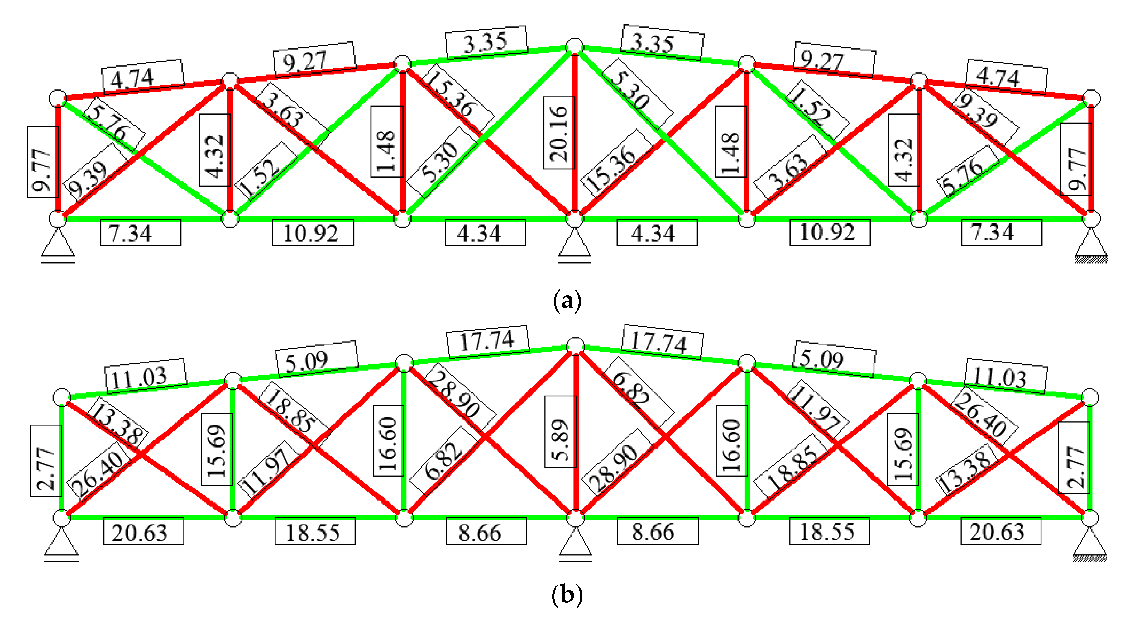
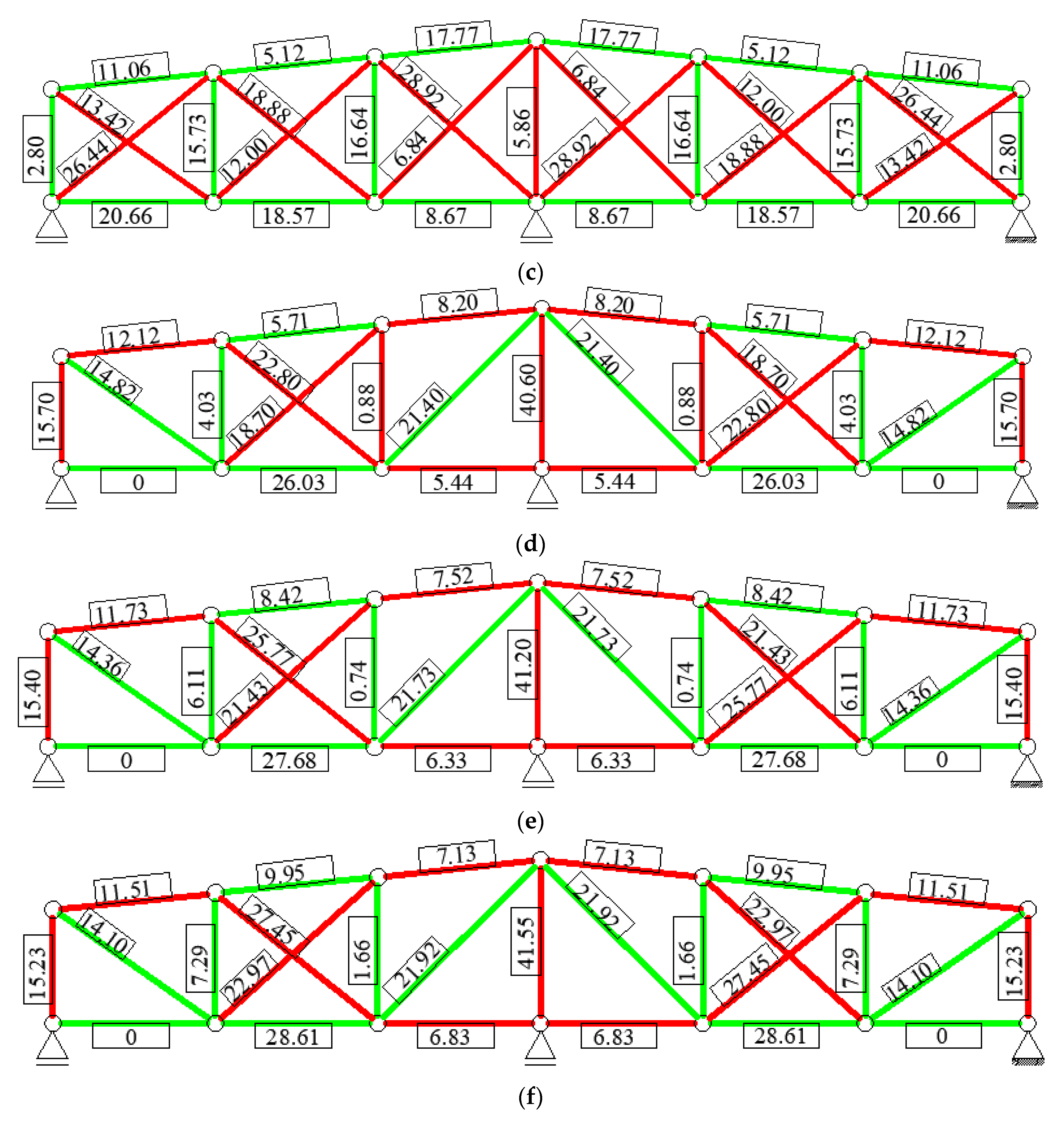
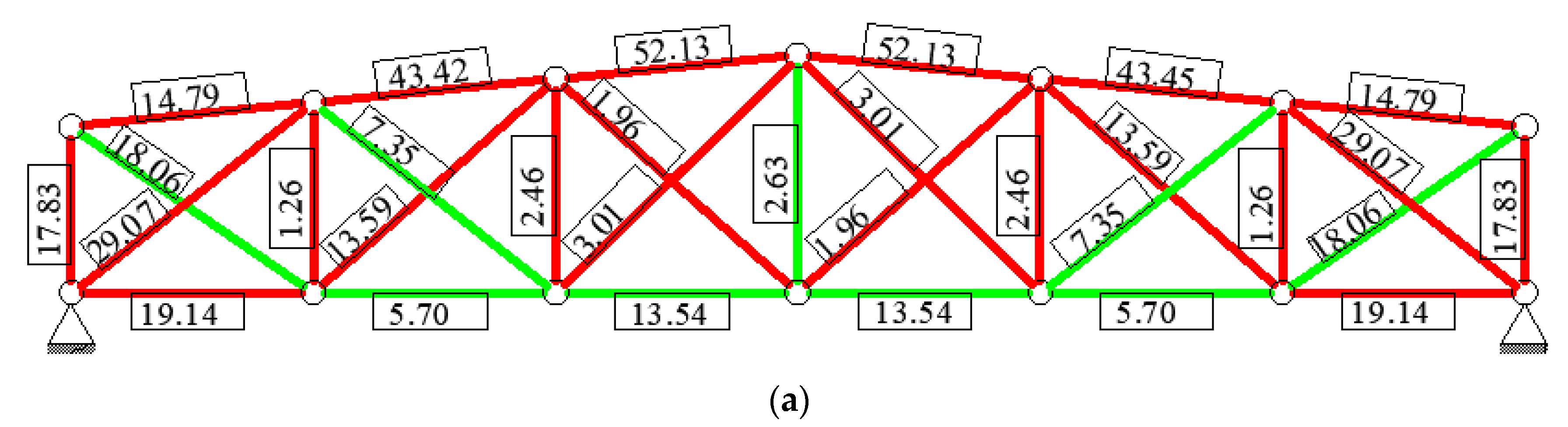
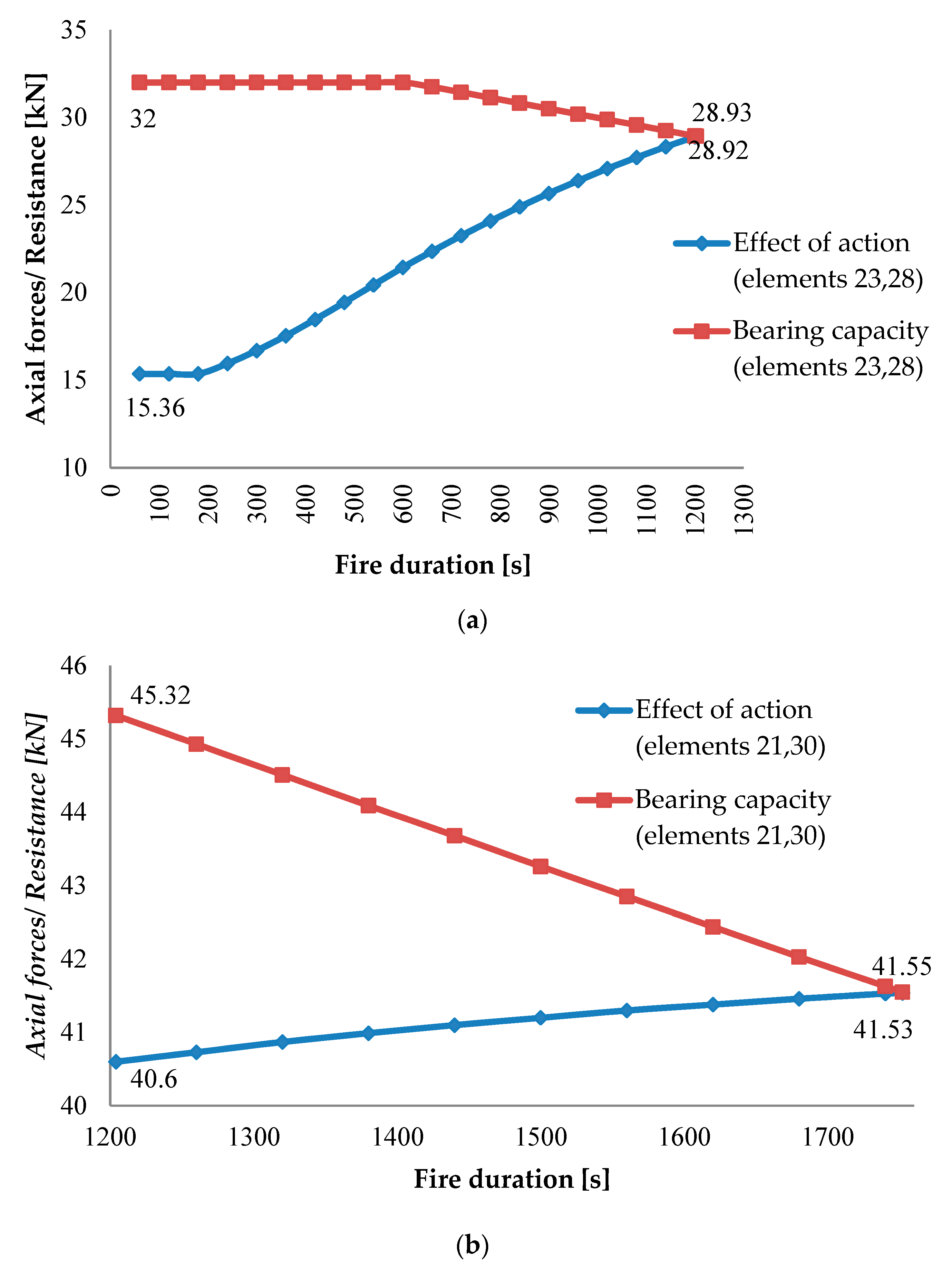
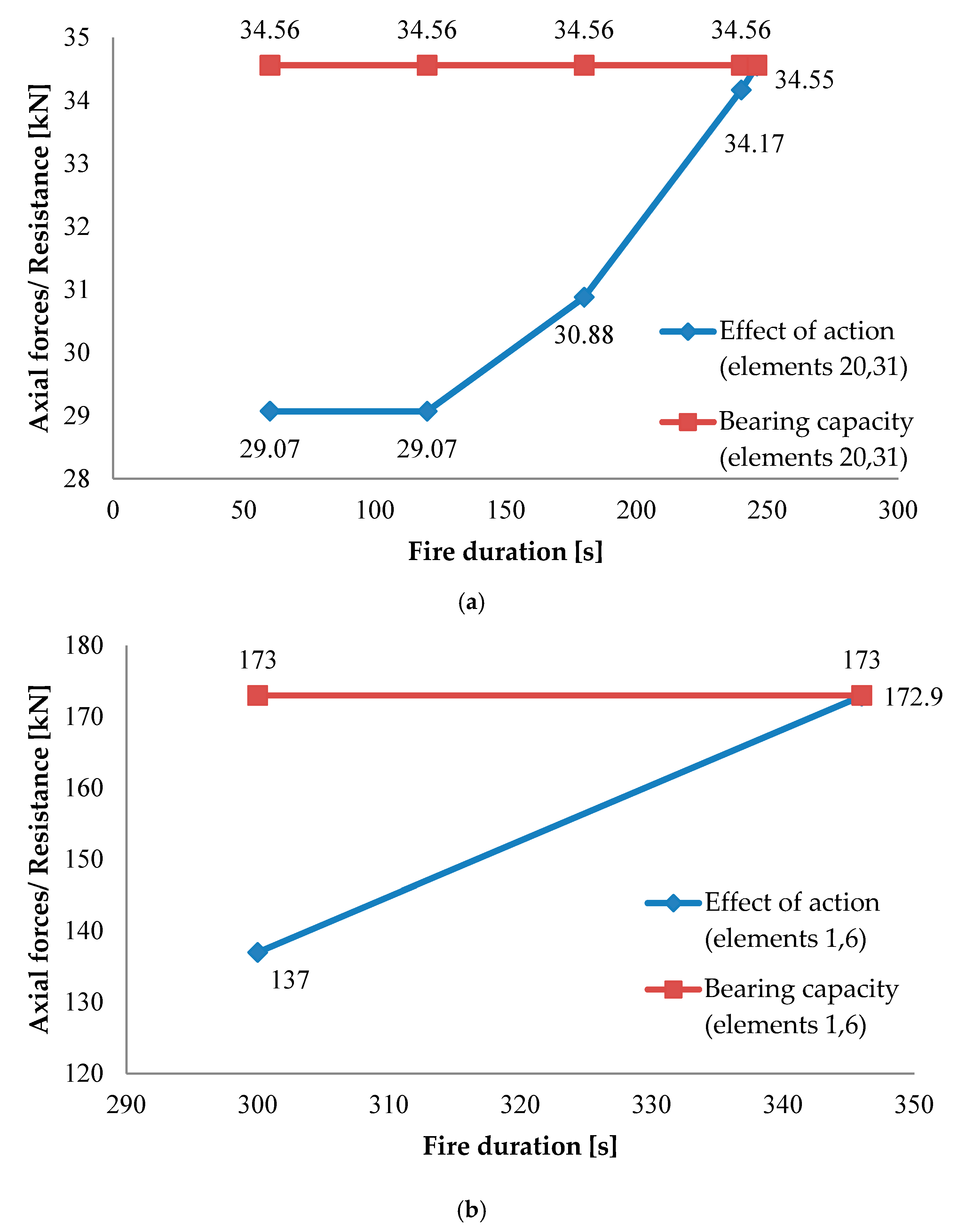
3.1. Thermal-Static Analysis

The presented analysis began with calculations of the temperature of combustion gases and elements of the structure in the passing minutes of a fire duration. In the analyzed examples, an increase in temperature leads to an exceeding the limit state of the bearing capacity of some rods, which results in a change in the static scheme of the structure. For truss “0”, consequently exceeded Ultimate Limit State ULS can be observed in symmetrically positioned cross-braces, starting from outermost elements (Figure 3a–c). Ultimately, after the 59th minute of the fire, the outermost posts buckle, which is equivalent to conversion of the structure into a mechanism.
In the case of truss “A”, the first change in the static scheme occurs after 20 min of the fire duration (tfi = 20.05 min (1203 s)). Buckling cross-braces belong to the outermost and central frames of the truss (Figure 4a). During the next several minutes (tfi = 29.2 min (1752 s)), ULS is exceeded in the central post and another pair of diagonals (Figure 4b). The current scheme (Figure 4b) is geometrically variable, which decides the conversion of the structure into a mechanism and the end of calculations.
In the case of truss “B”, changes of the static scheme occur in a much earlier phase of the fire (Figure 5). The buckling of outermost diagonals (Figure 5a) occurs already after 4 min of the combustion gases exposition (tfi = 4.12 min (247 s)). During the following minutes (tfi = 5.75 min (345 s)), the structure is converted into a mechanism due to the exceeding bearing capacity of the outermost elements of the bottom chord (Figure 5b).
Under the fire load, the significant changes in the value of axial forces (which are in the analyzed task associated with the effect of action) and bearing capacity are observed. Figure 6 and Figure 7 present changes in axial forces in the passing seconds of fire duration for the selected elements of truss, which were the deciding ones for static scheme change. The numeration of rods is compliant with this presented in Figure 2. In the case of “A” truss, 23 and 28 elements exceeded ULS first with fire duration (Figure 6a). Directly after that, extreme cross-braces exceeded bearing capacity (Figure 4a). In the following seconds of fire, rods numbered 21 and 30 (Figure 6b) were “the weakest” elements, and then middle post-element 16 exceeded collapse criterion (buckling) (Figure 4b). For the “B” truss, with only a few minutes of fire duration, the elements numbered 20 and 31 exceeded failure criterion (buckling) (Figure 7a). In the few following seconds of fire duration, the ULS of extreme elements of bottom chord (Figure 5b and Figure 7b) was exceeded and the structure became the mechanism. The analysis of the changes of axial forces during fire for all elements of both trusses is presented in Appendix A. In the case of truss “A” (Figure 6), changes are not too abrupt, and they are closely related to changes in the static scheme. Entirely reversed dynamics of changes are observed in the case of truss “B” (Figure 7). In this case, the value of axial forces in the elements of the bottom chord increases rapidly with every passing minute, which decides the very fast conversion of the structure into a mechanism. The distribution of axial forces in the passing minutes of fire duration for truss “0” is presented in the article [26].

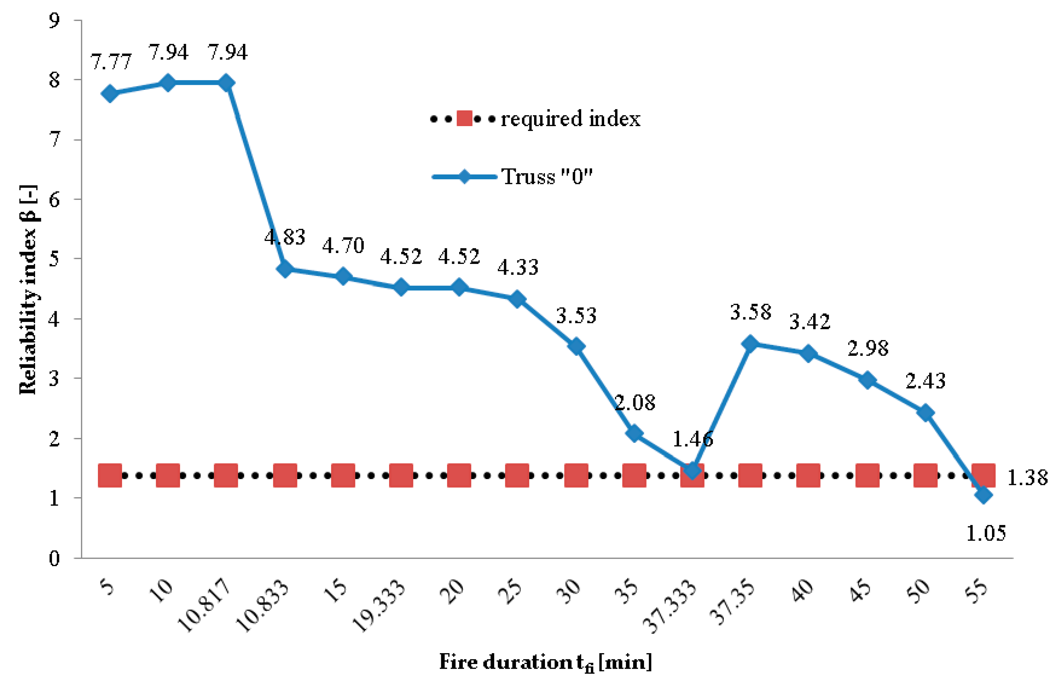
3.2. Reliability Analysis

As mentioned at the beginning of the article, the performance of a system analysis requires the identification of all kinematically admissible failure mechanisms for the given structure. This task was accomplished using a computing module prepared in the Mathematica environment [27,28]. In the case of the analyzed subject, after each change in the static scheme it becomes necessary to determine new KAFMs, because they are related to the geometry of the truss that undergoes the change. For the analyzed trusses, there is a considerable number of KAFMs, which complicates the task and prevents the performance of calculations without the use of computer methods. The identified KAFMs were divided into groups based on the number of causative elements. Table 1, Table 2 and Table 3 list the quantity of KAFMs for individual static schemes. Table 1 presents results related to truss “0”. Due to the capabilities of the computer and the time-consuming KAFM search algorithm, for truss “A” with an initial static scheme (Figure 4a), it was not possible to obtain an eight-element KAFM. The authors’ experience indicates that mechanisms deciding about reliability include those with very small numbers of causative elements. Therefore, this mechanism was excluded from the calculations. The reliability of such a complex mechanism is very close to one, which does not affect the final result.
It is not possible to present the whole reliability calculation procedure in the article due to the complexity of calculations. Nonetheless, a fragment of them will be presented in order to illustrate the method. It involves truss “B” after the first change of the static scheme (Figure 5a). Geometry of the truss along with the current numbering of rods are presented in Figure 8. Figure 9 presents the schemes of reliability system characteristics for the analyzed truss. Due to the fact that the fourth, fifth, and sixth KAFMs are characterized by a large number of causative elements (Table 3), the figure presents only the first and the last frame of the system.
The first KAFM corresponds to a serial system; therefore, based on the Formula (9), its reliability is calculated as a product of the reliabilities of individual elements:
R I = R 7 R 12 R 13 R 19 R 24 R 25
A mixed system appears in the case of KAFM II. Therefore, at first it is necessary to calculate the reliability of individual frames. If elements connected in series appear in a given frame, it is necessary to calculate the product of their reliability, followed by the reliability of elements connected in parallel according to Formula (10). With the assumption about the separation of mechanisms with common elements, it can be presumed that individual frames are connected to each other in series [32]. Therefore, the reliability of KAFM II will be calculated in the following manner:
R I I = [ 1 ( 1 R 1 ) ( 1 R 6 ) ] [ 1 ( 1 R 8 ) ( 1 R 14 R 20 R 26 ) ] [ 1 ( 1 R 9 ) ( 1 R 21 R 27 ) ] [ 1 ( 1 R 10 ) ( 1 R 22 R 28 ) ]                     [ 1 ( 1 R 11 ) ( 1 R 18 R 23 R 29 ) ] [ 1 ( 1 R 14 ) ( 1 R 20 R 26 ) ] [ 1 ( 1 R 18 ) ( 1 R 23 R 29 ) ]                     [ 1 ( 1 R 20 ) ( 1 R 26 ) ] [ 1 ( 1 R 21 ) ( 1 R 27 ) ] [ 1 ( 1 R 22 ) ( 1 R 28 ) ] [ 1 ( 1 R 23 ) ( 1 R 29 ) ]
The subsequent KAFMs have the nature of mixed systems. The manner of their calculation is presented below. Because KAFM IV, V, and VI are highly complex, they are shown in part, presenting calculations for the first and last frame only.
R I I I = [ 1 ( 1 R 1 ) ( 1 R 2 ) ( 1 R 8 R 14 R 20 R 26 ) ] [ 1 ( 1 R 1 ) ( 1 R 3 ) ( 1 R 9 R 21 R 27 ) ]                         [ 1 ( 1 R 1 ) ( 1 R 4 ) ( 1 R 10 R 22 R 28 ) ] [ 1 ( 1 R 1 ) ( 1 R 5 ) ( 1 R 11 R 18 R 23 R 29 ) ]                         [ 1 ( 1 R 2 ) ( 1 R 6 ) ( 1 R 8 R 14 R 20 R 26 ) ] [ 1 ( 1 R 3 ) ( 1 R 6 ) ( 1 R 9 R 21 R 27 ) ]                         [ 1 ( 1 R 4 ) ( 1 R 6 ) ( 1 R 10 R 22 R 28 ) ] [ 1 ( 1 R 5 ) ( 1 R 6 ) ( 1 R 11 R 18 R 23 R 29 ) ]                         [ 1 ( 1 R 8 ) ( 1 R 15 ) ( 1 R 9 R 21 R 27 ) ] [ 1 ( 1 R 9 ) ( 1 R 15 ) ( 1 R 14 R 20 R 26 ) ]                         [ 1 ( 1 R 9 ) ( 1 R 16 ) ( 1 R 10 R 22 R 28 ) ] [ 1 ( 1 R 10 ) ( 1 R 16 ) ( 1 R 21 R 27 ) ]                         [ 1 ( 1 R 10 ) ( 1 R 17 ) ( 1 R 11 R 18 R 23 R 29 ) ] [ 1 ( 1 R 11 ) ( 1 R 17 ) ( 1 R 22 R 28 ) ]                         [ 1 ( 1 R 14 ) ( 1 R 15 ) ( 1 R 21 R 27 ) ] [ 1 ( 1 R 15 ) ( 1 R 20 ) ( 1 R 21 R 27 ) ]                         [ 1 ( 1 R 15 ) ( 1 R 26 ) ( 1 R 21 R 27 ) ] [ 1 ( 1 R 16 ) ( 1 R 21 ) ( 1 R 22 R 28 ) ]                         [ 1 ( 1 R 16 ) ( 1 R 27 ) ( 1 R 22 R 28 ) ] [ 1 ( 1 R 17 ) ( 1 R 18 ) ( 1 R 22 R 28 ) ]                         [ 1 ( 1 R 17 ) ( 1 R 22 ) ( 1 R 23 R 29 ) ] [ 1 ( 1 R 17 ) ( 1 R 28 ) ( 1 R 23 R 29 ) ]
R I V = [ 1 ( 1 R 1 ) ( 1 R 2 ) ( 1 R 15 ) ( 1 R 3 R 9 R 21 R 27 ) ]   [ 1 ( 1 R 16 ) ( 1 R 17 ) ( 1 R 21 R 27 ) ( 1 R 18 R 23 R 29 ) ]
R V = [ 1 ( 1 R 1 ) ( 1 R 2 ) ( 1 R 15 ) ( 1 R 16 ) ( 1 R 4 R 10 R 22 R 28 ) ]   [ 1 ( 1 R 15 ) ( 1 R 16 ) ( 1 R 17 ) ( 1 R 20 R 26 ) ( 1 R 18 R 23 R 29 ) ]
R V I = [ 1 ( 1 R 1 ) ( 1 R 2 ) ( 1 R 15 ) ( 1 R 16 ) ( 1 R 17 ) ( 1 R 11 R 18 R 23 R 29 ) ]   [ 1 ( 1 R 5 ) ( 1 R 6 ) ( 1 R 15 ) ( 1 R 16 ) ( 1 R 17 ) ( 1 R 8 R 14 R 20 R 26 ) ]
With the valid assumption involving the separation of mechanisms with common elements, the reliability of the entire system presented in Figure 9 is calculated in a serial manner:
R = R I R I I R I I I R I V R V R V I
The reliability of each of the analyzed trusses along with the development of a fire was calculated with the use of the method described above. Figure 10, Figure 11 and Figure 12 present the changes in the value of the reliability index (β) as a function of fire duration. The minimum required value was adopted as β = 1.34 [35]. It is essential to take into account the fact that the probability of the failure when we consider the fire situation is a conditional probability, which is defined as follows [36]:
p f = P ( f a i l u r e / f i r e ) = P ( f i r e f a i l u r e ) / P ( f i r e )
where P ( f i r e f a i l u r e ) has been adopted equal to 7.23 × 10 5 in accordance with β = 3.8. It should be noted that this value corresponds to a reference period of 50 years. The probability P(fire) is estimated as the probability of the random event occurring in the following sequence: a fire has been initiated AND has not been effectively extinguished. Computationally, this probability is the product of probabilities of a fire ignition ( p i g n i t i o n ) and the failure of extinguishing the fire by: occupants ( p f o c c u p a n t s ), sprinklers ( p f s p r i n k l e r ), and fire brigade ( p f f i r e   b r i g a d e ). All these values were adopted according to [37]. Ultimately, obtained in this way a value of reliability index is equal to β = 1.34 [36]. It is worth to notice that this value is in a broad agreement with economically optimal target levels for fire safety according to [38]. Furthermore, such an agreement can be observed in the case of other accidental situation, e.g., gas explosions [39].
Figure 10 presents a change in reliability index for truss “0” [24]. The subsequent graphs (Figure 11 and Figure 12) present the drop in the reliability index along with the fire duration (for trusses “A” and “B”, respectively); results corresponding to truss “0” are presented for comparative purposes. In the case of truss “A” (Figure 11), the graph does not begin until the moment in time corresponding to the first change in the static scheme. Before that, in spite of the increase in axial forces and the decrease in bearing capacity along with the increase in temperature, the probability of failure remained as Pf = 0, which for mathematical reasons prevents the determination of the reliability index. This indicates that the structure was “over-rigidified” in some way, meaning that the values of bearing capacity of specific elements were considerably higher in relation to the effect of actions. In turn, after a change of the static scheme, the index has a safe value. However, attention is drawn by the very abrupt drop in its value, visible in particular when comparing the results with truss “0”. In addition, there is another quick change of the static scheme, corresponding to the conversion of the structure into a mechanism.
In the case of truss “B”, the reliability index is maintained at an almost constant level until a change of the static scheme (Figure 12). Nonetheless, the blockade of deformations of the bottom chord proves to be disadvantageous enough for the structure to stop working safely after changes of the static scheme, before six minutes of exposure to combustion gases have passed. This fact proves how important it is to provide the structure with the freedom of thermal deformations, when it is subject to the impact of high temperatures. The comparison of the results obtained for truss “0” [24] and truss “B” (Figure 12) clearly indicates how less safe a solution it is to choose a structure with the blockade of thermal deformations.
An analysis of the abovementioned graphs (Figure 10, Figure 11 and Figure 12) indicates that a structure with the “weakest” manner of support from the calculations point of view in the permanent design situation may prove to be the “strongest” under fire conditions.

4. Discussion

The objective of the article involved analyzing the impact of the method of supporting a plane steel truss on its behavior under fire conditions. The reliability index β was adopted as the measure of safety of a structure in this accidental design situation. It was determined using the system analysis. It involved a truss with an additional intermediate support (truss “A”) and a truss in which the manner of support blocked the freedom of thermal deformations of the bottom chord (truss “B”). In the case of truss “A”, until the 20th minute of the fire, the probability of failure amounted to zero. This means that the truss had very little strain. In such a case, it is not possible to calculate the reliability index. For truss “A”, the first value of the reliability index was not reached until the occurrence of a change of the static scheme of the structure. Although this value was initially relatively high, it dropped rapidly along with the development of the fire. Before the 30th minute of the fire, there was a second change in the static scheme, resulting in the conversion of the structure into a mechanism. Such behavior of the structure is quite surprising, since it turns out that the structure, which was over-dimensioned in the basic situation, does not necessarily have to be safe under the fire conditions. With the assumptions adopted for the description of a fire and fire insulation, the analyzed truss did not even reachR30 fire resistance class. An even more dangerous phenomenon can be observed in the case of truss “B”. The blockade of free thermal deformations in the bottom chord leads to the generation of high axial forces under the impact of temperature. In the case of the analyzed truss, they lead to a change of the static scheme already after the fourth minute of fire duration. From that moment on, the decrease in the value of the reliability index of the structure is very rapid, which causes it to become lower than what is required before the sixth minute of the fire. In this case, there is no fire resistance class to speak of. The results corresponding to truss “0”, which differs from trusses “A” and “B” only in the manner of support, are listed for comparative purposes only. In this case, three degrees of freedom are taken away (for trusses “A” and “B”—four). It turns out that, for the fire conditions, the selection of truss “0” proves to be the safest. The performed analysis suggests that the introduction of any additional bonds to the structure in the case of a fire-related design situation is dangerous. However, this conclusion should be verified, which the authors intend to do in future publications. The results produced for truss “B” are not surprising. On the other hand, in the case of truss “A” an advantageous effect was to be expected involving the unloading of the bottom chord, while an additional support decided about considerable deterioration of the fire resistance of the structure (compared to truss “0”). Subsequent changes of the static scheme of truss “A” suggest that this support limited the possibility of free elongation of central cross-braces and the middle post, which decided about the generation of considerable compressive axial forces leading to an exceeded ULS in these elements. It should be concluded that the behavior of a steel structure under the conditions of a fire is difficult to predict. A detailed fire analysis should be performed to ensure its safety. It is not enough to just check whether the limit state of bearing capacity is fulfilled in the minute corresponding to the desired fire resistance class. It is recommended to analyze the entire course of the fire, since there is high likelihood of the occurrence of changes of the static scheme along with its development. It is necessary to calculate the moment in time in which this happens and continue calculations for a structure with a new static scheme starting from this point.

5. Conclusions

The objective of the article involved analyzing the impact of the method of supporting a plane steel truss on the value of reliability index under fire conditions. The only trend of change of reliability index was found. The array of assumption was adopted to simplify the task. The results obtained in the analysis indicated how important it is to provide the structure freedom of the thermal expansion while the thermal loads are considered. This is the topic that was brought up in many publications and such a conclusion may seem to be obvious. But the results presented in the article indicate how rapidly structures with thermal deformation blockade can exceed the ULS under fire conditions. Furthermore, the analysis indicated that additional supports did not improve the resistance of truss while it is under thermal load. The complete opposite effect was observed.
All trusses presented in the article changed the static scheme with the fire duration, so the conclusion is that it is essential to lead the analysis of the structure under fire in the following minutes of exposition on the temperature. The consideration of the structure in only particular minutes is not adequate.
The system analysis used in the paper is a tool that enables obtaining a measure of safety in the form of the reliability index β for the entire structure. The use of this value is convenient and easy to interpret. The very process of determining this index with known KAFMs is quite difficult. However, the authors were able to overcome this problem using computer-based methods.
The presented paper and the conclusions should not be extrapolated to the situation not covered by the assumption pointed in part two. The conducted analysis has an initial character, and in further research, authors will limit the assumptions to get more realistic results. Especially, the probabilistic model should be improved by taking into account different types of loads (also climatic), appropriate types of distribution (not only normal), and the probabilistic character of the temperature load, generated with a fire duration.

Author Contributions

Introduction was prepared by K.K. and U.R. Mathematical description was written by K.K. and U.R. Results were obtained by K.K. The analysis of the results and conclusions were written by K.K. and U.R. Original draft were prepared by K.K. and supervised by U.R. All authors have read and agreed to the published version of the manuscript.

Funding

This research received no external funding.

Conflicts of Interest

The authors declare no conflict of interest.

Appendix A

This appendix contains figures that illustrate the change of axial forces with fire duration for trusses “A” (Figure A1) and “B” (Figure A2). The green color indicates elements in tension and the red, compressed ones.
Figure A1. Cross-sectional forces of truss “A” in the passing minutes of a fire: (a) tfi = 0 min; (b) tfi = 20 min; (c) tfi = 20.05 min (1203 s); (d) tfi = 20.07 min (1204 s); (e) tfi = 25 min; and (f) tfi = 29.2 min (1752 s).
Applsci 10 07916 g0a1aApplsci 10 07916 g0a1b
Figure A2. Cross-sectional forces of truss “B” in the passing minutes of a fire: (a) tfi = 0 min, 1 min; (b) tfi = 2 min; (c) tfi = 3 min; (d) tfi = 4.1 min (246 s); (e) tfi = 4.12 min (247 s); (f) tfi = 5min; and (g) tfi = 5.73 min (344 s).
Applsci 10 07916 g0a2aApplsci 10 07916 g0a2b

References

  1. Biegus, A. Fire damages and steel building roof repairs. In Proceedings of the XXVI Confererence “Awariebudowlane”, Międzyzdroje, Poland, 21–24 May 2013. (In Polish). [Google Scholar]
  2. Bramhanand, V.; Patil, M.; Ramgir, S. Study of structural steel members under thermal loading. Int. J. Sci. Eng. Technol. Res. 2016, 5, 2775–2781. [Google Scholar]
  3. Porcari, G.-L.F.; Zalok, E.; Mekky, W. Fire induced progressive collapse of steel building structures: A review of the mechanisms. Eng. Struct. 2015, 82, 261–267. [Google Scholar] [CrossRef]
  4. Pournaghshband, A.; Afshan, S.; Theofanous, M. Elevated temperature performance of restrained stainless steel beams. Structures 2019, 22, 278–290. [Google Scholar] [CrossRef]
  5. Khademi, F. Enhancing Load Rating of Railway Truss Bridges through a Hybrid Structural Analysis and Instrumentation Procedure. Ph.D. Thesis, Illinois Institute of Technology, Chicago, IL, USA, 2017. [Google Scholar]
  6. Khademi, F. Load Rating of Railway Bridges by Analysis and Testing. Master’s Thesis, Illinois Institute of Technology, Chicago, IL, USA, 2015. [Google Scholar]
  7. Grubišić, M.; Ivošević, J.; Grubišić, A. Reliability analysis of reinforced concrete frame by finite element method with implicit limit state functions. Buildings 2019, 9, 119. [Google Scholar] [CrossRef] [Green Version]
  8. Zabojszcza, P.; Radoń, U. The impact of node location imperfections on the reliability of single-layer steel domes. Appl. Sci. 2019, 9, 2742. [Google Scholar] [CrossRef] [Green Version]
  9. Low, B.K. FORM, SORM, and spatial modelling in geotechnical engineering. Struct. Saf. 2014, 49, 56–64. [Google Scholar] [CrossRef]
  10. Zhao, Y.-G.; Ono, T. A general procedure for first/second order reliability method (FORM/SORM). Struct. Saf. 1999, 21, 95–112. [Google Scholar] [CrossRef]
  11. Far, M.S.; Wang, Y. Approximation of the Monte Carlo Sampling Method for reliability analysis of structures. Math. Probl. Eng. 2019, 2016, 1–9. [Google Scholar]
  12. Anosh, J. Monte Carlo with Importance Sampling Markow Chain Monte Carlo Methods in Quantum Field Theories: A Modern Primer. arXiv 2020, arXiv:1912.10997. [Google Scholar]
  13. Potrzeszcz-Sut, B. Reliability analysis of shell truss structure by hybrid Monte Carlo Method. J. Theor. Appl. Mech. 2020, 58, 469–482. [Google Scholar] [CrossRef]
  14. Zabojszcza, P.; Radoń, U. Stability analysis of the single-layer dome in probabilistic description by the Monte Carlo method. J. Theor. Appl. Mech. 2020, 58, 425–436. [Google Scholar] [CrossRef]
  15. Hassoun, M.H. Fundamentals of Artificial Neural Networks; MIT Press: Cambridge, MA, USA; London, UK, 1955. [Google Scholar]
  16. Dudzik, A.; Potrzeszcz-Sut, B. The structural reliability analysis using explicit neural state functions. MATEC Web Conf. 2018, 262, 1–6. [Google Scholar] [CrossRef]
  17. Thoft-Christensen, P.; Baker, M.J. Structural Reliability Theory and Its Applications; Springer: Berlin/Heidelberg, Germany; New York, NY, USA, 1982. [Google Scholar]
  18. Thoft-Christensen, P.; Baker, M. Application of Structural Systems Reliability Theory; Springer: Berlin/Heidelberg, Germany, 1986. [Google Scholar]
  19. Qiu, Z.; Yang, D.; Elishakoff, I. Probabilistic interval reliability of structural systems. Int. J. Solids Struct. 2008, 45, 2850–2860. [Google Scholar] [CrossRef] [Green Version]
  20. Silicki, A.; Silicka, E. The method of optimum strengthening of spatial steel truss with usage of sensitivity analysis of the system reliability index. Pomiary Automatyka Kontrola 2010, 56, 613–616. (In Polish) [Google Scholar]
  21. Mochocki, W.; Obara, P.; Radoń, U. Impact of the wind load probability distribution and connection types on the reliability index of truss towers. J. Theor. Appl. Mech. 2020, 58, 403–414. [Google Scholar] [CrossRef]
  22. Mochocki, W.; Radoń, U. Analysis of basic failure scenarios of a truss tower in a probabilistic approach. Appl. Sci. 2019, 9, 2662. [Google Scholar] [CrossRef] [Green Version]
  23. Kubicka, K.; Radoń, U. Influence of the buckling coefficient randomness on the reliability index value under fire conditions. Arch. Civ. Eng. 2018, 64, 173–179. [Google Scholar] [CrossRef] [Green Version]
  24. Inerhunwa, I.; Wang, Y.C.; Su, M. Reliability analysis of intumescent coating protected steel members under the standard fire condition. Fire Saf. J. 2019, 104, 43–56. [Google Scholar] [CrossRef]
  25. Balogh, T.; Vigh, L.G. Complex and comprehensive method for reliability calculation of structures under fire exposure. Fire Saf. J. 2016, 86, 41–52. [Google Scholar] [CrossRef] [Green Version]
  26. Kubicka, K.; Obara, P.; Radoń, U.; Szaniec, W. Assessment of steel truss fire safety in terms of the system reliability analysis. Arch. Civ. Mech. Eng. 2019, 19, 417–427. [Google Scholar] [CrossRef]
  27. Kłosowska, J.; Obara, P.; Gilewski, W. Self-stress control of real civil engineering tensegrity structures. In Proceedings of the 22nd International Conference on Computer Methods in Mechanics (CMM) 2017, Lublin, Poland, 13–16 September 2017; Volume 1922. [Google Scholar]
  28. Gilewski, W.; Kłosowska, J.; Obara, P. The influence of self-stress on behavior of tensegrity-like real structure. In Proceedings of the 26th R-S-P Seminar on Theoretical Foundation of Civil Engineering, Warsaw, Poland, 19–21 August 2017; Volume 117. [Google Scholar]
  29. European Committee for Standardization. Eurocode 1: Actions on Structures Part 1–2: General Actions: Actions on Structures Exposed to Fire; PN-EN1991-1-2; CEN-CENELEC: Brussels, Belgium, 2002. [Google Scholar]
  30. European Committee for Standardization. Eurocode 3: Design of Steel Structures Part 1-2: General Rules—Structural Fire Design; PN-EN1993-1-2; CEN-CENELEC: Brussels, Belgium, 2005. [Google Scholar]
  31. Franssen, J.M.; Real, P.V. Fire Design of Steel Structures, 2nd ed.; John Wiley & Sons: Hoboken, NJ, USA, 2015. [Google Scholar]
  32. Turkowski, P.; Sulik, P. The Fire Design of Steel Structures According to Eurocode 3; Instytut Techniki Budowlanej: Warsaw, Poland, 2015. (In Polish) [Google Scholar]
  33. Kubicka, K.; Pawlak, U.; Radoń, U. Influence of the thermal insulation type and thickness on the structure mechanical response under fire conditions. Appl. Sci. 2019, 9, 2606. [Google Scholar] [CrossRef] [Green Version]
  34. Biegus, A. Probabilistic Analysis of Steel Structures; PWN: Wroclaw, Poland, 1977. (In Polish) [Google Scholar]
  35. JCSS Probabilistic Model Code. Available online: https://www.jcss-lc.org/jcss-probabilistic-model-code/ (accessed on 2 October 2020).
  36. Maślak, M. Assessment of the safety level ensured by a steel load-bearing structure when subjected to a fire. In Proceedings of the ICASS 2015: Eighth International Conference on Advances in Steel Structures; IJSSD 2015 Symposium on Progress in Structural Stability and Dynamics, Lisbon, Portugal, 21–24 July 2015. [Google Scholar]
  37. Fontana, M.; Favre, J.P.; Fetz, C. A survey of 40,000 buildings fires in Switzerland. Fire Saf. J. 1999, 32, 137–158. [Google Scholar] [CrossRef]
  38. Hopkin, D.; Fu, I.; Van Coile, R. Adequate fire safety for structural steel elements based upon life-time cost optimization. Fire Saf. J. 2020, in press. [Google Scholar] [CrossRef]
  39. Hingorani, R.; Tanner, P.; Zanuy, C. Life safety risk based requirements for concrete structures in accidental situations caused by gas explosions. Struct. Saf. 2019, 76, 184–196. [Google Scholar] [CrossRef]
Figure 1. The layout of a system: (a) serial and (b) parallel.
Applsci 10 07916 g001
Figure 2. Geometry of analyzed trusses: (a) a truss with one hinged movable support and one hinged nonmovable support (truss “0”); (b) a truss with an additional intermediate support (truss “A”); and (c) a truss with the blockade of free thermal deformations (truss “B”).
Applsci 10 07916 g002
Figure 3. Change in the static scheme of truss “0” along with the fire duration: (a) tfi = 10.83 min (650 s); (b) tfi = 20 min (1200 s); (c) tfi = 37.35 min (2241 s); and (d) tfi = 59.75 min (3585 s).
Applsci 10 07916 g003
Figure 4. Change in the static scheme of truss “A” along with the fire duration: (a) tfi = 20.05 min (1203 s) and (b) tfi = 29.2 min (1752 s).
Applsci 10 07916 g004
Figure 5. Change in the static scheme of a truss with the blockade of free thermal deformations along with the fire duration: (a) tfi = 4.12 min (247 s) and (b) tfi = 5.75 min (345 s).
Applsci 10 07916 g005
Figure 6. The change of axial forces and resistance with fire duration (truss “A”): (a) elements 23, 28 and (b) elements 21, 30.
Applsci 10 07916 g006
Figure 7. The change of axial forces and resistance with fire duration (truss “B”): (a) elements 20, 31 and (b) elements 1, 6.
Applsci 10 07916 g007
Figure 8. The numbering of rods in truss “B” after first reduction.
Applsci 10 07916 g008
Figure 9. Schemes of the reliability system of truss “B” after the first reduction.
Applsci 10 07916 g009
Figure 10. Change in the reliability index of truss “0”.
Applsci 10 07916 g010
Figure 11. Change in the reliability index of truss “A”.
Applsci 10 07916 g011
Figure 12. Change in the reliability index of truss “B”.
Applsci 10 07916 g012
Table 1. Kinematically admissible failure mechanisms for truss “0” [26].
Number of Causative ElementsStatic Scheme I (Figure 2a)Static Scheme II (Figure 3a)Static Scheme III (Figure 3b)Static Scheme IV (Figure 3c)
1-81625
2443220
3885625
47240
55625
640
725
Σ3251616125
Table 2. Kinematically admissible failure mechanisms for truss “A”.
Number of Causative ElementsStatic Scheme I (Figure 2b)Static Scheme II (Figure 4a)
12
2882
330362
4724169
52118
62945
75510
8no result
Σ>8335615
Table 3. Kinematically admissible failure mechanisms for truss “B”.
Number of Causative ElementsStatic Scheme I (Figure 2c)Static Scheme II (Figure 5a)
16
22419
35161
4240163
5603252
6759178
7616
8312
Σ2605679
Publisher’s Note: MDPI stays neutral with regard to jurisdictional claims in published maps and institutional affiliations.

