Article

Development of 340-GHz Transceiver Front End Based on GaAs Monolithic Integration Technology for THz Active Imaging Array

1
School of Electronic Science and Engineering, University of Electronic Science and Technology of China, Chengdu 611731, China
2
National Key Laboratory of Application Specific Integrated Circuit, Hebei Semiconductor Research Institute, Shijiazhuang 050000, China
*
Author to whom correspondence should be addressed.
Appl. Sci. 2020, 10(21), 7924; https://doi.org/10.3390/app10217924
Submission received: 8 October 2020 / Revised: 4 November 2020 / Accepted: 5 November 2020 / Published: 9 November 2020
(This article belongs to the Special Issue Terahertz Sensing and Imaging)

Abstract

:
Frequency multipliers and mixers based on Schottky barrier diodes (SBDs) are widely used in terahertz (THz) imaging applications. However, they still face obstacles, such as poor performance consistency caused by discrete flip-chip diodes, as well as low efficiency and large receiving noise temperature. It is very hard to meet the requirement of multiple channels in THz imaging array. In order to solve this problem, 12-μm-thick gallium arsenide (GaAs) monolithic integrated technology was adopted. In the process, the diode chip shared the same GaAs substrate with the transmission line, and the diode’s pads were seamlessly connected to the transmission line without using silver glue. A three-dimensional (3D) electromagnetic (EM) model of the diode chip was established in Ansys High Frequency Structure Simulator (HFSS) to accurately characterize the parasitic parameters. Based on the model, by quantitatively analyzing the influence of the surface channel width and the diode anode junction area on the best efficiency, the final parameters and dimensions of the diode were further optimized and determined. Finally, three 0.34 THz triplers and subharmonic mixers (SHMs) were manufactured, assembled, and measured for demonstration, all of which comprised a waveguide housing, a GaAs circuit integrated with diodes, and other external connectors. Experimental results show that all the triplers and SHMs had great performance consistency. Typically, when the input power was 100 mW, the output power of the THz tripler was greater than 1 mW in the frequency range of 324 GHz to 352 GHz, and a peak efficiency of 6.8% was achieved at 338 GHz. The THz SHM exhibited quite a low double sideband (DSB) noise temperature of 900~1500 K and a DSB conversion loss of 6.9~9 dB over the frequency range of 325~352 GHz. It is indicated that the GaAs monolithic integrated process, diodes modeling, and circuits simulation method in this paper provide an effective way to design THz frequency multiplier and mixer circuits.

1. Introduction

Over the past few decades, various terahertz (THz) technologies have been developed rapidly. Among them, THz imaging and sensing technology have broad application prospects in science and other fields, such as safety and security screening, process monitoring, non-contact material testing, radio astronomy, and earth observation [1,2,3,4,5,6,7,8,9]. In recent years, many active or passive imaging systems based on all-solid-state electronics technology have been reported at the submillimeter and THz band [9,10,11,12,13,14,15]. Transmitters with sufficient output power are inevitably required for active imagers, and the core device is usually frequency multipliers. Low-noise and broadband receivers are necessarily needed in THz imaging systems. These receivers are mainly based on Schottky diodes or III/V compound semiconductor transistors.
THz sources based on gallium nitride (GaN) or complementary metal oxide semiconductor (CMOS) technology have been widely studied. GaN Schottky diode-based sources show better performance in high power dissipation, up to 1.1 W, but the efficiency is much lower than that of GaAs-based circuits [16,17]. THz sources based on silicon/SiGe CMOS around 300 GHz have also been reported, which generally show great advantages of high integration. However, the maximum output power of only −4.6 dBm and −6.5 dBm and optimum efficiency of only 1.4% and 0.052% are presented, respectively [18,19]. THz sources based on Schottky diodes possess many advantages, including compactness, broadband, frequency stability, temperature stability, and capability of room temperature operation [20,21,22]. In recent years, remarkable progress has been made in the field of solid-state THz sources based on planar Schottky diodes. In pursuit of high working frequency, a tripler operating from 2.5 to 2.7 THz was reported by Jet Propulsion Laboratory [23]. In terms of high efficiency, a 220 GHz tripler with a peak efficiency of 16% was reported by Virginia Diodes, Inc. [24]. However, discreet GaAs Schottky varactor diode chips are used in [24]. Since the highly consistent performance of the circuits is a big concern for subsequent research on active radar imaging arrays, GaAs monolithic integrated diode chips are preferred to design THz triplers.
THz subharmonic mixers (SHMs) based on GaAs Schottky diodes have also been rapidly developed due to the advantage of low noise and broadband performance at room temperature [25,26,27,28]. They directly help improve the signal-to-noise rate (SNR) of the entire receiver, especially when there is no proper wideband THz low noise amplifier (LNA) in the system. In [29], a 190–240 GHz Schottky-diode SHM with lower than 1500 K noise temperature is presented. However, the use of flip-chip anti-parallel Schottky diodes may no longer be suitable for higher frequency THz mixers, which face the problems of poor alignment and position uncertainty of the diode and the passive circuits. Therefore, GaAs monolithic integrated technology is an effective and necessary alternative when the operating frequency exceeds 300 GHz.
In this paper, 0.34 THz triplers and SHMs based on GaAs Schottky diodes are proposed for THz active imaging applications. The tripler and mixer are used as the solid-state transmitter and receiver front end, respectively. First, the GaAs process, diodes modeling, and the development of 0.34 THz triplers and SHMs are described in detail in Section 2. Compared with the traditional method of mounting discrete diodes on circuits, the 12-μm-thick GaAs monolithic integrated process in this paper reduces manual assembly errors, lowers the defective rate, and improves performance consistency. Moreover, when the frequency goes beyond 0.3 THz, the parasitic parameters introduced by the physical geometry of the Schottky diodes have a non-negligible effect on the frequency conversion efficiency of either multipliers or mixers. To address this issue, a 3D EM model of the diode chip is established in HFSS software to accurately characterize the parasitic parameters. Based on the 3D EM model and the co-simulation method, by analyzing different surface channel widths and anode junction areas, the best frequency conversion efficiency can be obtained, thereby finally determining the dimension of the diode chip. The approach adopted in this paper is a combination of 3D full-wave EM simulation and harmonic balanced simulation. Measurements and results about the output capacity of the triplers and the noise temperature of the SHMs agree well with the simulation results.

2. Materials and Methods

2.1. Schottky Diodes

As a crucial component in THz multipliers and mixers, GaAs Schottky barrier diodes SBDs were developed first. In this paper, the 12-μm-thick GaAs monolithic integrated technology was jointly developed by the University of Electronic Science and Technology of China (UESTC) and Hebei Semiconductor Research Institute, Shijiazhuang. The main physical and electrical diode parameters for the 0.34 THz tripler and the 0.34 THz mixer are listed in Table 1 and Table 2, respectively. Typical cut-off frequency (fT) is also given, which is defined as 1/(2πRsCj0), where Rs and Cj0 represent series resistance and zero-bias junction capacitance of the Schottky-barrier diode, respectively. A detailed description is given about the process and design of the 4-die diode chip for the tripler, and that of the anti-parallel diode chip for the mixer was similar.
Active layers (n GaAs epitaxial layer and the highly doped n+ GaAs buffer layer) were built on the semi-insulating (SI) GaAs substrate with a thickness of 12 μm. The doping concentration of the GaAs buffer layer was 5 × 1018 cm−3, which created conditions for the ohmic contact between the cathode and the active layer. The thickness of the buffer layer was 3.5 μm, which was slightly larger than the skin depth at the operating frequency. The thickness of the epilayer was set to 0.3 μm, which was slightly larger than the thickness of the depletion layer under the reverse breakdown voltage to avoid introducing more series resistance. The cylindrical anode was formed on the epitaxial layer, resulting in the Schottky contact. The anode radius was 1.8 μm (corresponding to an area of 10.8 μm2), which is a key parameter for designing tripler and will be discussed later. The SiO2 layer was deposited on the epitaxial layer to protect the epilayer. The SiO2 passivation layer introduced parasitic parameters, and the smaller the thickness, the smaller the parasitic parameters introduced. According to the process conditions, the thickness of the oxide layer was determined to be 0.5 μm. The cathode pad and the metal layer of the transmission line were realized and connected by electroplating with a thickness of 1 μm. A straight surface channel was etched to lower parasitic capacitance, as shown in Figure 1. The spacing between the two straight mesas was 8.5 μm, which is elaborated later in this paper. In addition, the overall size of the 4-die diode chip was 224 μm in length, 28 μm in width, and 6.3 μm in height, not counting the thickness of the substrate. It was essential to use those physical parameters to build a three-dimensional modeling of the diode.
In terms of lumped equivalent circuits, a large amount of literature is available on the modeling of Schottky diodes in millimeter and submillimeter waves operating at room temperature [30,31,32,33]. For this design, a simplified equivalent circuit model was used, which is marked on the cross-sectional view in Figure 1. The Schottky junction is represented by a diode symbol, modeled as voltage-dependent junction capacitance (Cj) and resistance (Rj). The diode’s series resistance (RS) consists of airbridge finger resistance (Rf), buffer-layer spreading resistance (Rspread), ohmic-contact resistance (Rohmic), and top junction epi-layer resistance. Several parasitic elements were used to characterize parasitic coupling effects dependent of the diode geometry, where the magnetic field coupling within the airbridge finger was modeled as Lf and electric field coupling near the surface channel was modeled as Cpp1, Cpp2, and Cfp. Based on these equivalent circuit components, the electrical parameters obtained through measurements are shown in Table 1 and Table 2. The equivalent model of the diode had to be slightly different, depending on the specific application. For multipliers, nonlinear junction capacitance Cj0 played a leading role, which could be improved by properly increasing the anode junction area and reducing the doping concentration of the epitaxial layer. However, mixers were more dependent on the nonlinear resistance characteristics of the diode junction because broadband impedance matching was easier to achieve when nonlinear resistance dominated. Additionally, the HFSS 3D model of the diode is presented at the bottom of Figure 1, including anti-series 4-die SBDs for 0.34 THz triplers and anti-parallel SBDs for 0.34 THz SHMs.

2.2. Geometry Optimization of Diodes

For a given input power and frequency, the best frequency multiplication efficiency varied with the geometry size of the diode, as well as bias conditions of direct current (DC). As shown in Figure 1, the surface channel was approximately equivalent to a plate capacitor and the air bridge finger mainly introduced inductance. When the width increased, Cpp decreased and Lf increased. On the contrary, Cpp increased and Lf decreased. Excessive inductance or capacitance increased the difficulty of impedance matching and reduced the cut-off frequency of the diode, thereby degrading the performance of the diode. Moreover, Rj and Cj were intrinsic parameters for representing the nonlinear effect of anode junction and they were also contradictory. When one parameter changed with the area of the anode junction, the other parameter changed in the opposite direction. Therefore, the diode geometry had to be optimized to achieve optimal multiplication efficiency. The area of the anode junction and the width of the surface channel were the main optimization objects.
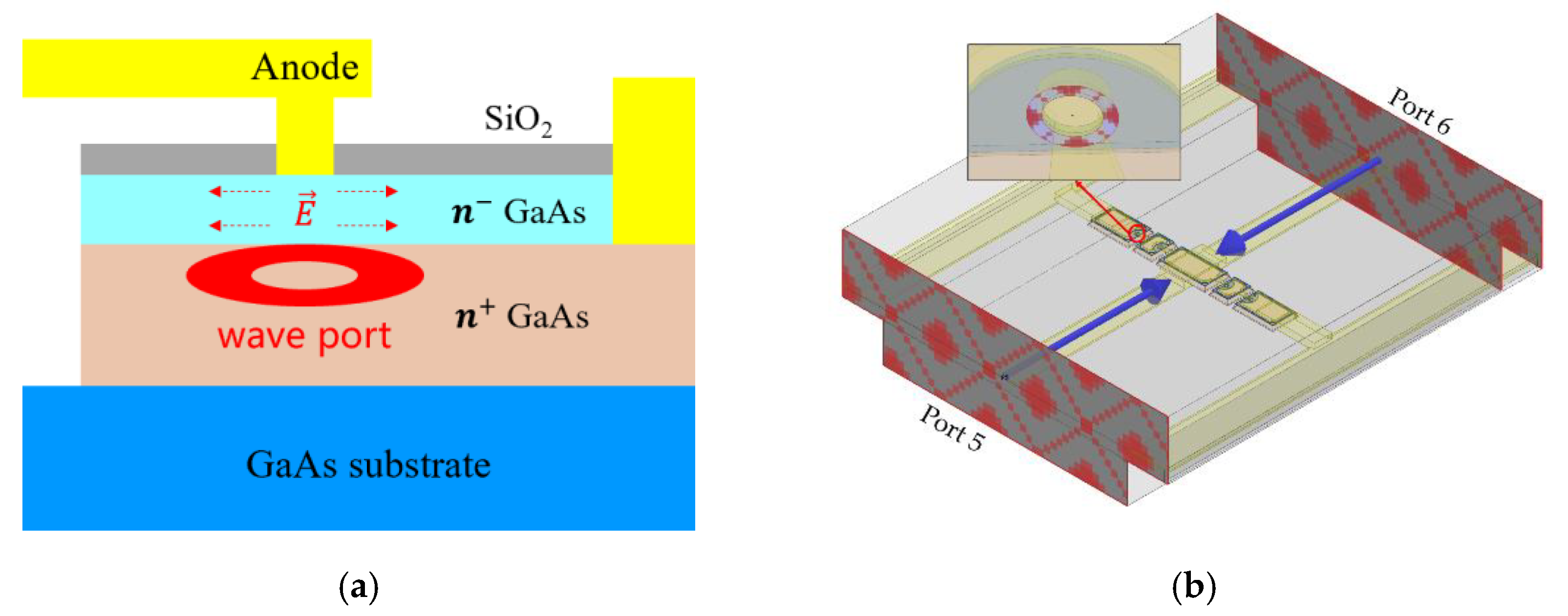
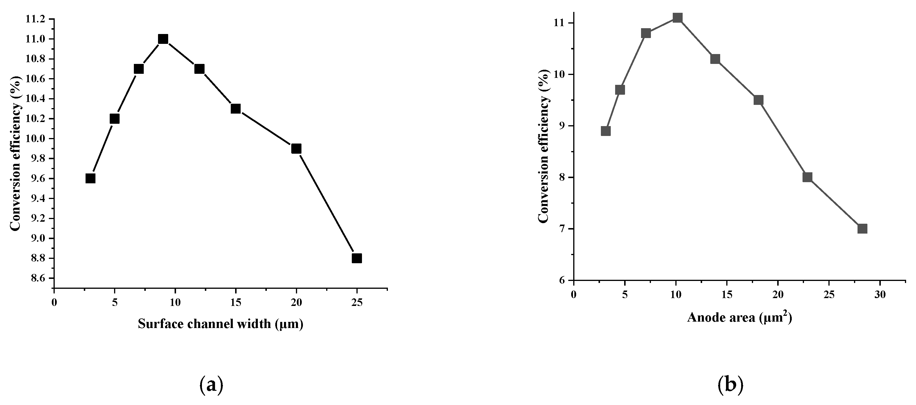
The schematic diagram of the wave port configuration of the diode anode junction and the setup for high-frequency 3D EM simulations is shown in Figure 2. Each diode’s wave port was defined as a miniature coaxial hollow ring piece surrounding the anode, as illustrated in Figure 2a. The electromagnetic field around the anode junction was calculated with HFSS. The gap between the edge of the anode and the coaxial hollow ring piece must be very narrow to avoid underestimating the parasitic capacitance [34]. The 4-die diode chip was embedded in the suspended microstrip line with both ends of the diode extended toward the two wave ports, numbered as 5 and 6, as shown in Figure 2b. The effect of the transmission line was removed by de-embedding the wave port to the diode chip. Thus, the 3D EM simulation model was set up and measured by the six wave ports. Using the obtained linear S-parameter results already considered the parasitic effects caused by the diode geometry, which is represented by the several parasitic elements in Figure 1. Harmonic balance simulation was then performed in Keysight Advanced Design System (ADS) to calculate the conversion efficiency. Finally, parametric sweep simulations were conducted for the circuit’s optimum performance under a specific channel width and anode junction area. The optimization results are shown in Figure 3a,b, from which we can see the best surface channel width of 8.5 μm and anode junction area of 10 μm2.

2.3. 0.34 THz Tripler Development

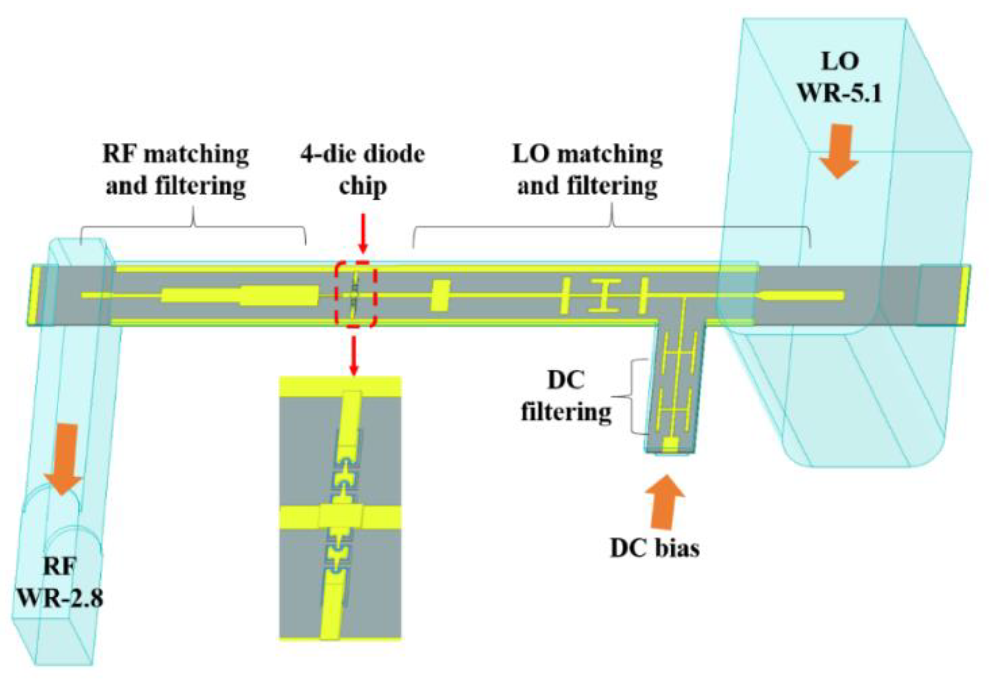
With the geometrically optimized diode chip, a 0.34 THz tripler using GaAs monolithic technology was proposed. The detailed circuit configuration is shown in Figure 4. It can be seen from the figure that the whole circuit was functionally divided into three parts. The 4-die diode chip generated the fundamental wave and the harmonics. The local oscillator (LO) matching and filtering part consisted of a LO transition probe for input, a filter based on a compact microstrip resonant cell (CMRC) for harmonics energy recovery, a CMRC filter for DC bias, and an intermediate matching circuit to make the input fundamental energy fed into the diode chip as much as possible. Similarly, the radio frequency (RF) matching and filtering part was optimized to maximize the output of the third harmonic. All linear circuit structures, including filters and matching networks, were simulated and designed in HFSS. S-parameter files with seven ports were then imported into ADS for harmonic balance simulation. After several iterations of co-simulation and optimization, the tripler circuit was finalized to suffice requirements, as shown in Figure 4.
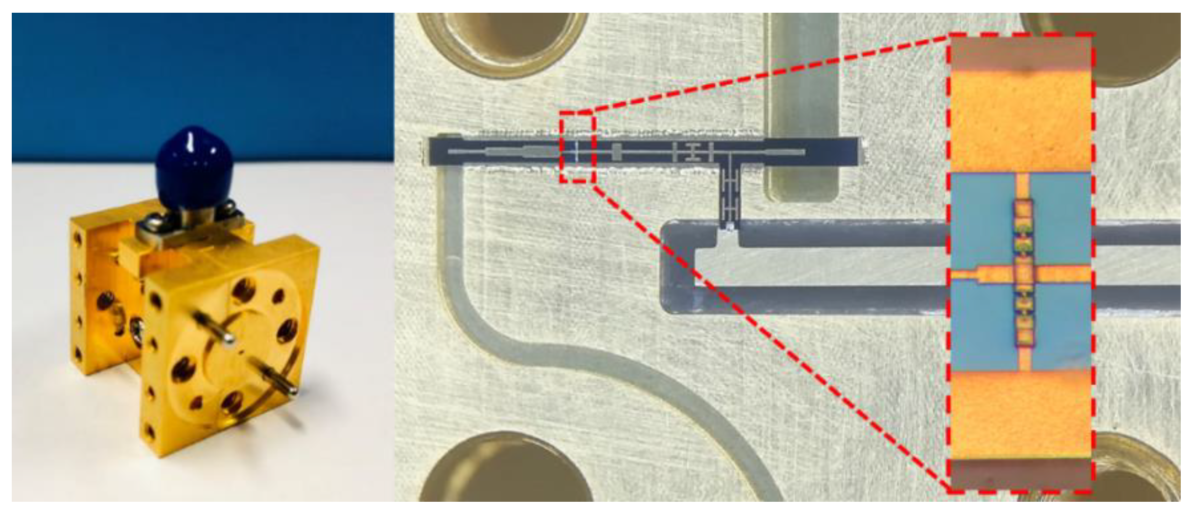
A photograph of the fabricated THz GaAs monolithic integrated tripler circuit within a split block is shown in Figure 5. As can be seen, the 4-die SBDs were integrated with the matching circuits, and the whole tripler circuit was fixed on the block through the beam lead. Due to the large relative dielectric constant of gallium arsenide, it was impractical to connect the tiny DC feeder circuit directly to the external subminiature version A (SMA) connector. Therefore, the transition circuit on Rogers RT/duroid 5880 was fabricated and connected to the GaAs circuit through silver glue. The zoomed view of the diode chip was given as proof that the monolithic integrated diode technology eliminated the manual assembly errors that may have been introduced by the flip-chip mounting of discrete diode chips. Simulation results show that the output power of the tripler was more than 3.6 mW in the frequency range of 324~352 GHz and reached the peak efficiency of 10.7% at 340 GHz under the condition that input power was 100 mW and bias voltage for each die was −1.95 V.

2.4. 0.34 THz SHM Development

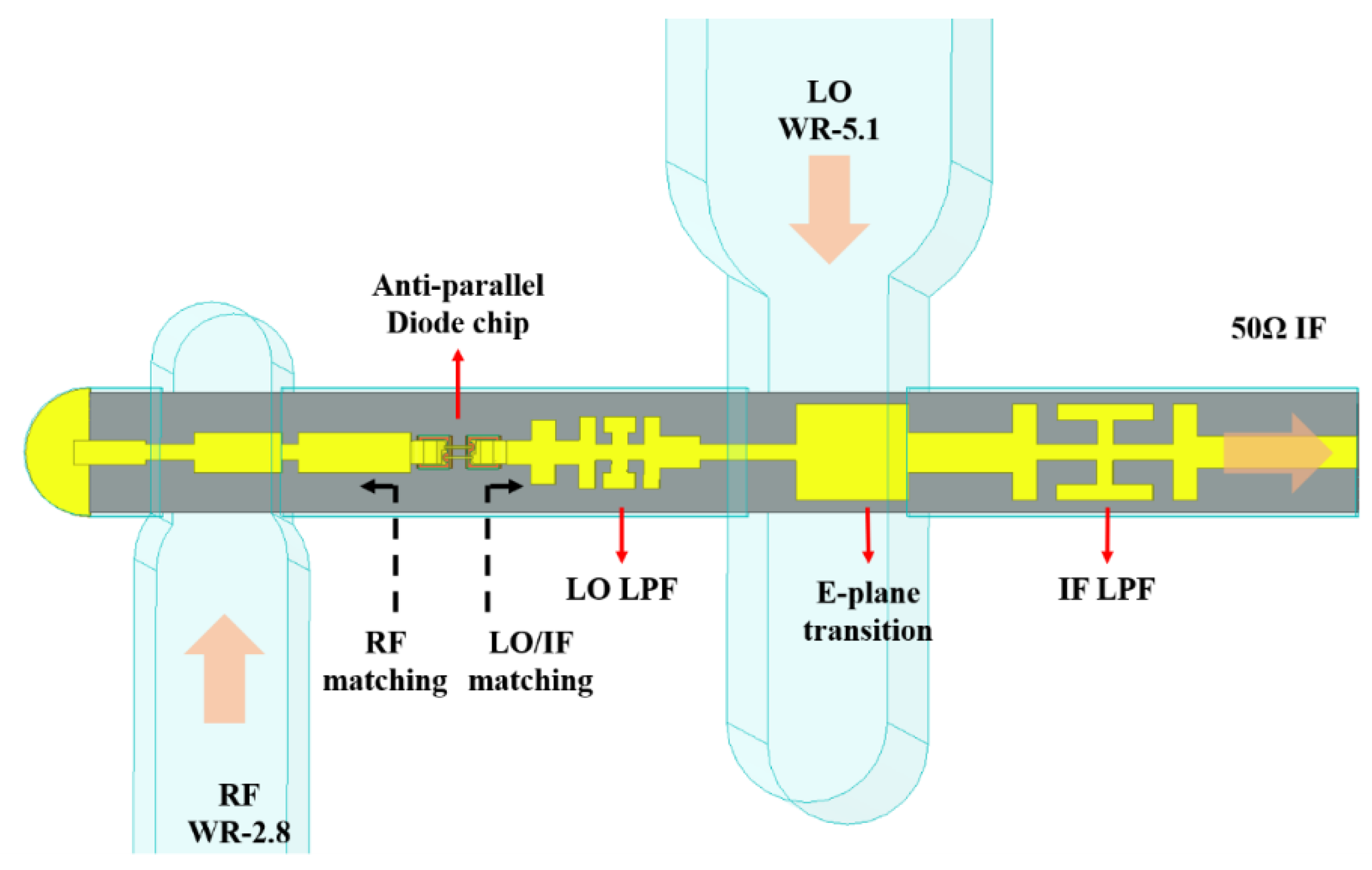
Based on the anti-parallel Schottky diode chip for mixers, whose parameters are listed in Table 2, a 0.34 THz SHM using GaAs monolithic technology was proposed. A further look at the 3D diode chip model and diode port configuration in HFSS is given in Figure 6. The integration line had to be assigned in the port definition to specify the current polarity of the diode to ensure that the subsequent construction of the co-simulation diagram was correct. The proposed circuit configuration of the monolithic integrated SHM is shown in Figure 7. As noted in the figure, it mainly consisted of three parts, among which the diode chip had already been designed and determined. The remaining task was to complete the design of RF matching and LO/IF (local oscillator or intermediate frequency) matching circuits distributed on the left and right ends of the diode chip, thereby improving conversion efficiency. After each part was optimized, such as LO/IF CMRC filters and E-plane transition probes, all the sub-circuits were combined with the diode chip for 3D electromagnetic simulation. The S-parameter file with five ports of the whole circuit, as shown in Figure 7, was then exported from HFSS to ADS and schematically reconstructed. Harmonic balance simulation was then carried out for the mixer circuit to predict performance. After several iterations of co-simulation, the SHM circuit was finalized.
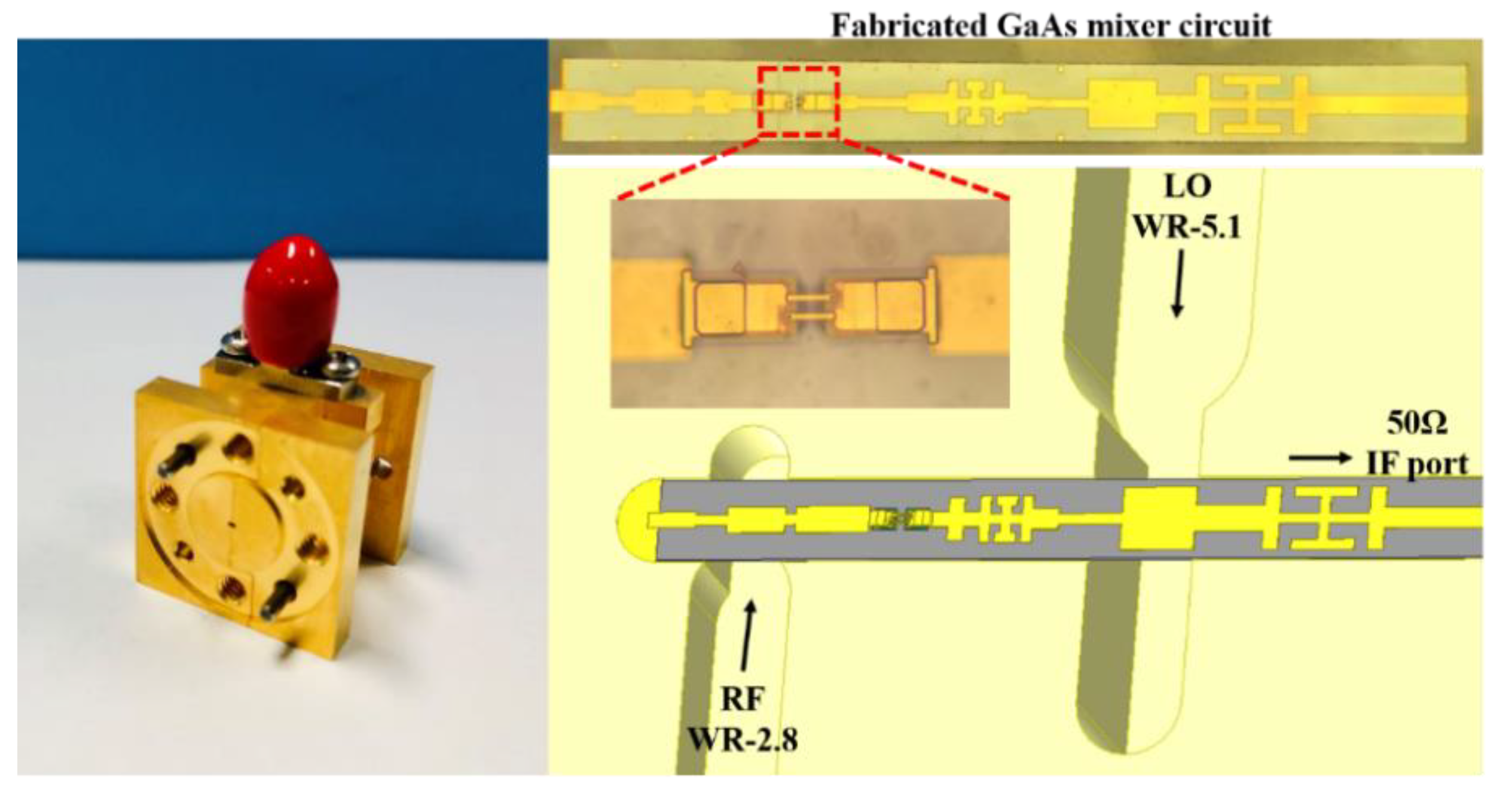
A photograph of the fabricated THz GaAs monolithic integrated SHM circuit and assembly diagram in the split block is shown in Figure 8. When the mixer was assembled, the entire GaAs mixer circuit was aligned, along with a suspended microstrip slot milled by a high-precision computerized numerical control (CNC) process and fixed in the metal block through adhesive silver glue. The IF output port was finally connected to a K connector through a 50 Ω transmission line realized on Rogers RT/duroid 5880 substrates. The simulation results showed that the double sideband (DSB) noise temperature and DSB conversion loss of SHM were lower than 1500 K and 8 dB, in the range of 321~354 GHz, respectively, and reached the lowest values of 697 K and 6.1 dB at 339 GHz.

2.5. Tolerance Analysis

We conducted tolerance analysis through simulation to estimate the impact of possible errors on device performance. In the actual fabrication process of triplers and mixers, potential errors may occur from substrate processing, cavity machining, and circuit assembly. Among them, the semiconductor technology ensured that the substrate processing error was guaranteed within 0.5 μm, which had a negligible impact on the circuit, working at 0.34 THz. However, the tolerance of cavity machining and circuit assembly were generally about ± 5 μm, which could not be ignored and would affect the performance of devices. Since the two types of error were relative, cavity machining error could be accumulated to the circuit assembly error, that is ±10 μm. Therefore, it can be simplified to only perform tolerance analysis on the positioning deviation during substrate assembly. Taking the Cartesian coordinate system as a reference, the GaAs integrated circuit moved ±10 μm in the x and y directions, as shown in Figure 9. The tolerance analysis simulation results and comparison with original simulation data are presented in Figure 10.
The shape and trend of the simulation curves agreed with the original result after the substrate was shifted, though there were still certain impacts on the center frequency, bandwidth, output power, or conversion loss, mainly caused by impedance variations at RF/LO transition probes, which affected the matching condition at the diode. Additionally, the effect depended more on the Rf transition structure because the absolute size was smaller. However, the deterioration of the circuit performance due to the substrate assembly error was acceptable, indicating that the circuits had a good tolerance to errors caused by substrate assembly.

3. Results and Discussions

Based on the self-designed Schottky diodes and GaAs monolithic integrated technology, 0.34 THz triplers and sub-harmonic mixers were fabricated. To verify the effectiveness of the diode design method and simulation optimization method proposed in this article, three triplers and three mixers were assembled and measured for the research on performance consistency.

3.1. 0.34 THz Triplers’ Performances

The tripler’s test diagram is shown in Figure 11, in which the frequency synthesizer Agilent E8257D provided frequency reference to the F-band driving source, which mainly featured the ×9 frequency multiplication and power amplification. A tunable attenuator was inserted between the tripler and the F-band source to easily adjust the wanted input power up to 100 mW. The Erickson PM5 waveguide power meter was used to measure the output power around 0.34 THz and calibrate the input power. When tested, the DC bias voltage was tuned to obtain the best performance within a certain frequency range.
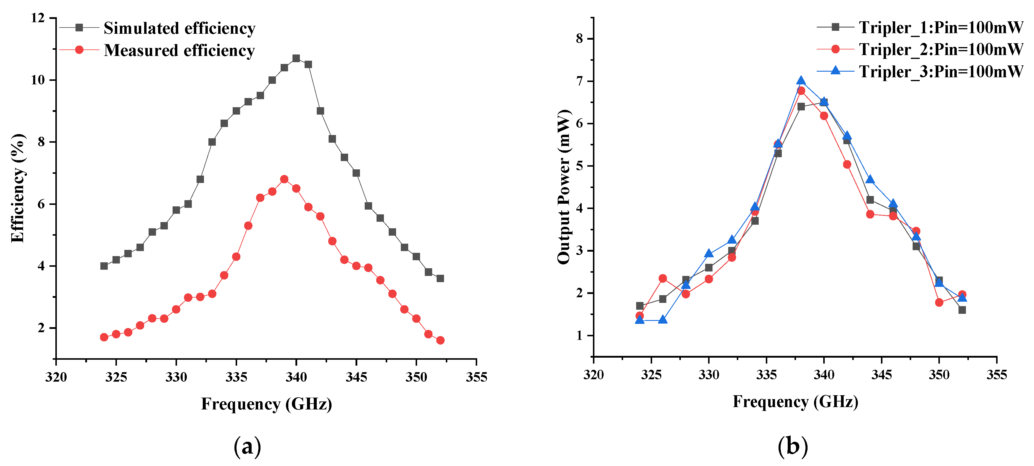
The performance of the tripler with different input power levels is depicted in Figure 12. With known input power and output power, efficiency can be calculated. As can be seen from the measurement results, a peak efficiency of 6.8% and maximum output power of 6.8 mW were obtained at 338 GHz with an input power of 100 mW and a DC bias voltage of −2.56 V. It was found that −1.28 V was the optimum bias voltage for every single Schottky die. In addition, the tripler showed greater than 1 mW output power in the range of 324 GHz−352 GHz when driven by 100 mW. From the perspective of the increasing tendency of output power with increasing input power from 50 mW to 100 mW, there was still room for further improvement in output power. It is indicated that the tripler still did not reach saturation when driven by 100 mW, which is currently already the highest available power, from 108 GHz to 117.33 GHz, in the lab. Moreover, a comparison between simulated and measured performance with 100 mW input power is given in Figure 13. Note that the measured curves had a similar trend to the simulated curves, though the measured conversion efficiency was a little lower. The frequency corresponding to the measured peak efficiency was close to the simulated frequency, implying the effectiveness of the diode design method and accuracy of performance prediction based on simulations in this work. Moreover, the measured results of the three triplers at room temperature are shown in Figure 13b. Note also that the three different triplers had very similar performance in terms of efficiency and bandwidth. This implies that the monolithic integration process proposed in this article is reliable and can ensure consistency between different products.

3.2. 0.34 THz Mixers’ Performances

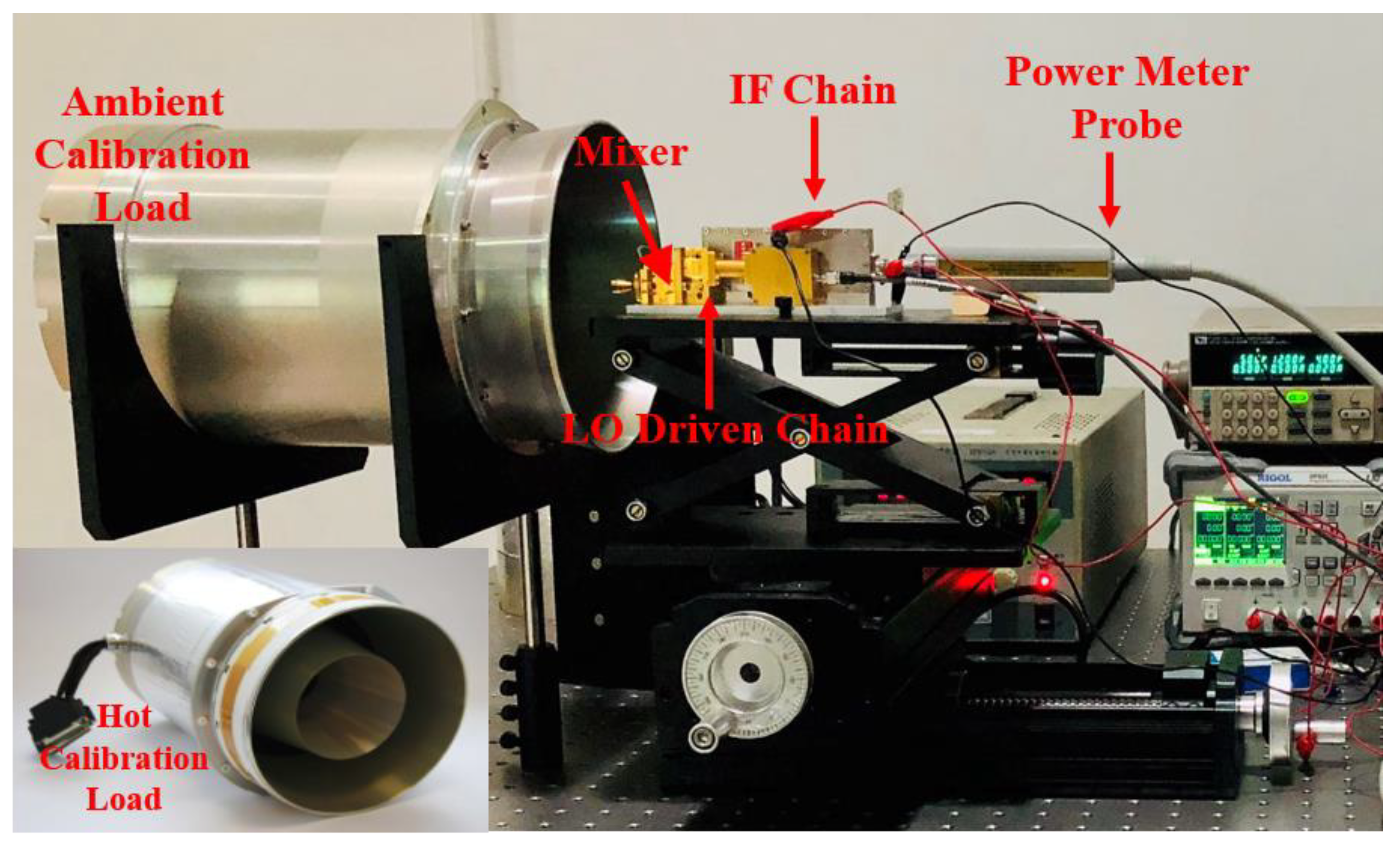
The SHM performances were characterized by the Y-factor method at room temperature. There have been many excellent reports about noise temperature measurement of THz receivers or mixers, such as [25,35], where the large temperature difference between LN2 and ambient loads (295/77 K) ensures test accuracy. In this paper, the ambient calibration load (288 K) and the hot calibration load (361 K) (from TK Inc.) were presented alternately at the input of the receiver through the feed horn antenna. The setup, illustrated in Figure 14 and Figure 15, was mounted on an optical table, and the experimental platform was relatively simpler. Furthermore, in order to reduce the test error, we removed unreliable data, such as too large or too small data when measuring, and the noise temperature at each frequency point was obtained by averaging multiple sets of valid data. The mixer’s LO was provided by a 170 GHz doubler driven by an E-band ×9 multiplication chain, with a maximum LO power up to 6 mW. As the power level radiated from the hot/ambient load was very low, a 60 dB high gain IF amplifier was cascaded at the IF output port of the mixer. The final amplified power was monitored by Agilent P-Series Power Meter N1911A with a wideband power sensor.
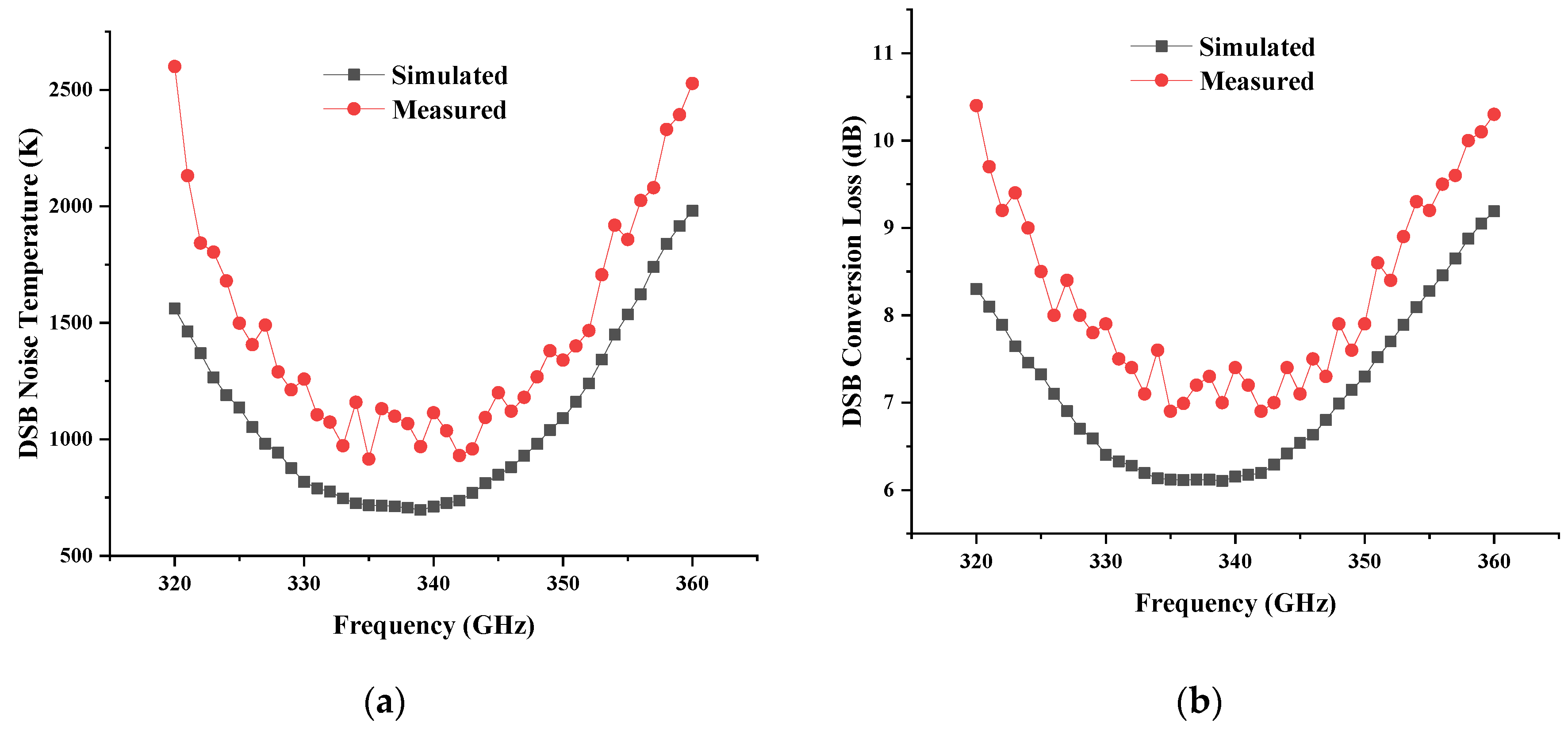
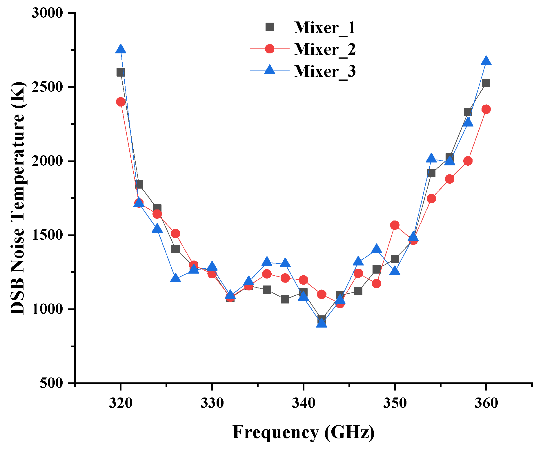
The DSB noise temperature and conversion gain of the receiver (including the SHM and IF chain) can be calculated through Y-factor measurement. Since the noise figure and gain of the IF chain were already known, the DSB noise temperature and conversion loss could be extracted according to methods detailed in [36]. Eventually, the measured performances of the SHM. in comparison with simulation results, were curved, as shown in Figure 16. The DSB noise temperature and DSB conversion loss of SHM were lower than 1500 K and 9 dB in the range of 325~352 GHz, respectively, and reached the lowest values of 915 K and 6.9 dB at 335 GHz. In fact, the deviation of the measured noise temperature from the simulation was within expectations. All the measured results included internal waveguide transmission loss, flange connection loss, and feed horn antenna loss. Furthermore, the hot temperature was difficult to ensure precisely and there was an error in the coupling from the horn to calibration loads. Moreover, the measured results of the three mixers at room temperature are shown in Figure 17. In terms of noise temperature or operating frequency, the performance of different mixer modules was only slightly different.
We also investigated published Schottky SHM performances in a similar frequency range, which are listed in Table 3. The DSB noise temperature and conversion loss of this work were close to or better than those reported in the other literature. Additionally, a hybrid integrated circuit with a flip-chip soldered diode chip was adopted in [37,38,39], which resulted in the inability to guarantee the consistency of multiple channels in a large array.

4. Conclusions

Taking THz active imaging array as the application background, 0.34 THz triplers, and mixers based on 12-μm-thick GaAs monolithic integrated process and Schottky diode chips, are proposed in this article. The diodes’ geometry was optimized first to achieve the best performance by quantitatively analyzing the physical dimensions of diodes. Based on the use of precise simulation tools, such as Ansoft HFSS and Agilent ADS, accurate electromagnetic modeling of the diode was carried out and the performance of triplers or mixers was predicted through co-simulation. Experimental results show that, at room temperature, by injecting 100 mW, the THz tripler could achieve a peak efficiency of 6.8% at 338 GHz. The output power of greater than 1 mW was achieved in the range of 324 GHz to 352 GHz. The THz SHM showed good performance, in that the DSB noise temperature was lower than 1500 K and the DSB conversion loss was lower than 9 dB in the frequency range of 325~352 GHz. Three frequency triplers and three mixers were processed and assembled and their performance was tested and compared. It is shown that they all show a high consistency in performance. The results of both the THz tripler and SHM agreed well with the simulations, thus verifying the validity of the design method proposed in this paper. To sum up, the GaAs monolithic integrated THz tripler and SHM proposed in this paper show good performance and provide support for future applications to THz active imaging arrays. However, in actual THz imaging applications, we are still facing challenges, such as limited operating range caused by large atmospheric attenuation, which can be tackled by power combining technology and III/V compound-based power amplifications to further increase transmit power.

Author Contributions

Conceptualization, Y.L., B.Z., and X.L.; methodology, Y.L. and Y.F. (Yinian Feng); software, Y.L. and Y.Y.; validation, Y.L., B.Z., and D.J.; investigation, Y.L. and Z.N.; resources, Y.L. and X.Z.; writing—original draft preparation, Y.L.; writing—review and editing, B.Z. and Y.F. (Yong Fan); supervision, Y.F. (Yong Fan); funding acquisition, B.Z. All authors have read and agreed to the published version of the manuscript.

Funding

This research was funded by the National Natural Science Foundation of China (NSFC) under Grant 91738102, Grant 61771116, and Grant 62022022.

Conflicts of Interest

The authors declare no conflict of interest.

References

  1. Anwar, M.; Fischer, B.M.; Dhar, N.K.; Demarty, Y.; Schneider, M.; Crowe, T.W.; Löffler, T.; Keil, A.; Quast, H. THz all-electronic 3D imaging for safety and security applications. In Proceedings of the SPIE 7671, Terahertz Physics, Devices, and Systems IV: Advanced Applications in Industry and Defense, Orlando, FL, USA, 26 April 2010; Volume 7671, p. 767111. [Google Scholar] [CrossRef]
  2. Hillger, P.; Grzyb, J.; Jain, R.; Pfeiffer, U.R. Terahertz Imaging and Sensing Applications With Silicon-Based Technologies. IEEE Trans. Terahertz Sci. Technol. 2019, 9, 1–19. [Google Scholar] [CrossRef]
  3. Hwu, R.J.; Zimdars, D.; Woolard, D.L.; White, J.S. Terahertz reflection imaging for package and personnel inspection. In Proceedings of the SPIE 5411, Terahertz for Military and Security Applications II, Orlando, FL, USA, 8 September 2004; Volume 5411, p. 78. [Google Scholar] [CrossRef]
  4. Kawase, K. Terahertz Imaging For Drug Detection And Large-Scale Integrated Circuit Inspection. Opt. Photonics News 2004, 15, 34–39. [Google Scholar] [CrossRef]
  5. Kawase, K.; Shibuya, T.; Hayashi, S.i.; Suizu, K. THz imaging techniques for nondestructive inspections. Comptes Rendus Phys. 2010, 11, 510–518. [Google Scholar] [CrossRef]
  6. Kulesa, C. Terahertz Spectroscopy for Astronomy: From Comets to Cosmology. IEEE Trans. Terahertz Sci. Technol. 2011, 1, 232–240. [Google Scholar] [CrossRef]
  7. Liu, H.-B.; Zhong, H.; Karpowicz, N.; Chen, Y.; Zhang, X.-C. Terahertz Spectroscopy and Imaging for Defense and Security Applications. Proc. IEEE 2007, 95, 1514–1527. [Google Scholar] [CrossRef]
  8. Shen, Y.C.; Lo, T.; Taday, P.F.; Cole, B.E.; Tribe, W.R.; Kemp, M.C. Detection and identification of explosives using terahertz pulsed spectroscopic imaging. Appl. Phys. Lett. 2005, 86, 241116. [Google Scholar] [CrossRef] [Green Version]
  9. Trichopoulos, G.C.; Mosbacker, H.L.; Burdette, D.; Sertel, K. A Broadband Focal Plane Array Camera for Real-time THz Imaging Applications. IEEE Trans. Antennas Propag. 2013, 61, 1733–1740. [Google Scholar] [CrossRef]
  10. Appleby, R.; Anderton, R.N. Millimeter-Wave and Submillimeter-Wave Imaging for Security and Surveillance. Proc. IEEE 2007, 95, 1683–1690. [Google Scholar] [CrossRef]
  11. Cooper, K.B.; Dengler, R.J.; Llombart, N.; Bryllert, T.; Chattopadhyay, G.; Schlecht, E.; Gill, J.; Lee, C.; Skalare, A.; Mehdi, I.; et al. Penetrating 3-D Imaging at 4- and 25-m Range Using a Submillimeter-Wave Radar. IEEE Trans. Microw. Theory Tech. 2008, 56, 2771–2778. [Google Scholar] [CrossRef] [Green Version]
  12. Cooper, K.B.; Dengler, R.J.; Llombart, N.; Thomas, B.; Chattopadhyay, G.; Siegel, P.H. THz Imaging Radar for Standoff Personnel Screening. IEEE Trans. Terahertz Sci. Technol. 2011, 1, 169–182. [Google Scholar] [CrossRef]
  13. Friederich, F.; Von Spiegel, W.; Bauer, M.; Meng, F.; Thomson, M.D.; Boppel, S.; Lisauskas, A.; Hils, B.; Krozer, V.; Keil, A.; et al. THz Active Imaging Systems With Real-Time Capabilities. IEEE Trans. Terahertz Sci. Technol. 2011, 1, 183–200. [Google Scholar] [CrossRef]
  14. Heinz, E.; May, T.; Born, D.; Zieger, G.; Anders, S.; Zakosarenko, V.; Meyer, H.G.; Schäffel, C. Passive 350 GHz Video Imaging Systems for Security Applications. J. Infrared Millim. Terahertz Waves 2015, 36, 879–895. [Google Scholar] [CrossRef]
  15. Chattopadhyay, G. Terahertz circuits, systems, and imaging instruments. In Proceedings of the 2014 39th International Conference on Infrared, Millimeter, and Terahertz waves (IRMMW-THz), Tucson, AZ, USA, 14–19 September 2014; pp. 1–2. [Google Scholar]
  16. Zhang, B.; Ji, D.; Fang, D.; Liang, S.; Fan, Y.; Chen, X. A Novel 220-GHz GaN Diode On-Chip Tripler With High Driven Power. IEEE Electron Device Lett. 2019, 40, 780–783. [Google Scholar] [CrossRef]
  17. Yang, Y.; Zhang, B.; Wang, Y.; Niu, Z.; Fan, Y. Development of High Power 220 GHz Frequency Triplers Based on Schottky Diodes. IEEE Access 2020, 8, 74401–74412. [Google Scholar] [CrossRef]
  18. Li, Y.; Goh, W.L.; Liu, C.; Cui, B.; Liu, H.; Xiong, Y.Z. A 324-GHz Source/Modulator With −6.5 dBm Output Power. IEEE Trans. Terahertz Ence Technol. 2015, 5, 412–418. [Google Scholar] [CrossRef]
  19. Vu, T.A.; Takano, K.; Fujishima, M. 300-GHz Balanced Varactor Doubler in Silicon CMOS for Ultrahigh-Speed Wireless Communications. IEEE Microw. Wirel. Compon. Lett. 2018, 28, 341–343. [Google Scholar] [CrossRef]
  20. Chattopadhyay, G. Technology, Capabilities, and Performance of Low Power Terahertz Sources. IEEE Trans. Terahertz Sci. Technol. 2011, 1, 33–53. [Google Scholar] [CrossRef]
  21. Mehdi, I.; Siles, J.V.; Lee, C.; Schlecht, E. THz Diode Technology: Status, Prospects, and Applications. Proc. IEEE 2017, 105, 990–1007. [Google Scholar] [CrossRef]
  22. Martin, S.; Nakamura, B.; Fung, A.; Smith, P.; Bruston, J.; Maestrini, A.; Maiwald, F.; Siegel, P.; Schlecht, E.; Mehdi, I. Fabrication of 200 to 2700 GHz multiplier devices using GaAs and metal membranes. In Proceedings of the International Microwave Symposium Digest, Phoenix, AZ, USA, 20–24 May 2001. [Google Scholar]
  23. Maestrini, A.; Mehdi, I.; Lin, R.; Siles, J.V.; Ward, J. A 2.5–2.7 THz room temperature electronic source. In Proceedings of the International Symposium on Space Terahertz Technology, Tucson, AZ, USA, 26–28 April 2011. [Google Scholar]
  24. Porterfield, D.W. High-Efficiency Terahertz Frequency Triplers. In Proceedings of the International Microwave Symposium, Honolulu, HI, USA, 3–8 June 2007. [Google Scholar]
  25. Treuttel, J.; Gatilova, L.; Maestrini, A.; Moro-Melgar, D.; Yang, F.; Tamazouzt, F.; Vacelet, T.; Jin, Y.; Cavanna, A.; Mateos, J. A 520–620-GHz Schottky Receiver Front-End for Planetary Science and Remote Sensing With 1070 K–1500 K DSB Noise Temperature at Room Temperature. IEEE Trans. Terahertz Ence Technol. 2016, 6, 148–155. [Google Scholar] [CrossRef]
  26. Thomas, B.; Maestrini, A.; Beaudin, G. A low-noise fixed-tuned 300-360-GHz sub-harmonic mixer using planar Schottky diodes. IEEE Microw. Wirel. Compon. Lett. 2005, 15, 865–867. [Google Scholar] [CrossRef]
  27. Schlecht, E.; Siles, J.V.; Lee, C.; Lin, R.; Thomas, B.; Chattopadhyay, G.; Mehdi, I. Schottky Diode Based 1.2 THz Receivers Operating at Room-Temperature and Below for Planetary Atmospheric Sounding. IEEE Trans. Terahertz Ence Technol. 2014, 4, 661–669. [Google Scholar] [CrossRef]
  28. Sobis, P.J.; Wadefalk, N.; Emrich, A.; Stake, J. A Broadband, Low Noise, Integrated 340 GHz Schottky Diode Receiver. IEEE Microw. Wirel. Compon. Lett. 2012, 22, 366–368. [Google Scholar] [CrossRef]
  29. Chen, Z.; Wang, H.; Alderman, B.; Huggard, P.; Zhang, B.; Fan, Y. 190 GHz high power input frequency doubler based on Schottky diodes and AlN substrate. Ieice Electron. Express 2016, 13, 20160981. [Google Scholar] [CrossRef] [Green Version]
  30. Tang, A.Y.; Drakinskiy, V.; Sobis, P.; Vukusic, J.; Stake, J. Modeling of GaAs Schottky diodes for terahertz application. In Proceedings of the International Conference on Infrared, Busan, Korea, 21–25 September 2009. [Google Scholar]
  31. Tang, A.Y.; Stake, J. Impact of Eddy Currents and Crowding Effects on High-Frequency Losses in Planar Schottky Diodes. IEEE Trans. Electron Devices 2011, 58, 3260–3269. [Google Scholar] [CrossRef] [Green Version]
  32. Tang, A.Y.; Drakinskiy, V.; Yhland, K.; Stenarson, J.; Bryllert, T.; Stake, J. Analytical Extraction of a Schottky Diode Model From Broadband S -Parameters. IEEE Trans. Microw. Theory Tech. 2013, 61, 1870–1878. [Google Scholar] [CrossRef]
  33. Tang, A.Y.; Schlecht, E.; Lin, R.; Chattopadhyay, G.; Lee, C.; Gill, J.; Mehdi, I.; Stake, J. Electro-Thermal Model for Multi-Anode Schottky Diode Multipliers. IEEE Trans. Terahertz Ence Technol. 2012, 2, 290–298. [Google Scholar] [CrossRef] [Green Version]
  34. Maestrini, A.; Ward, J.S.; Gill, J.J.; Javadi, H.S.; Schlecht, E.; Tripon-Canseliet, C.; Chattopadhyay, G.; Mehdi, I. A 540–640-GHz high-efficiency four-anode frequency tripler. IEEE Trans. Microw. Theory Tech. 2005, 53, 2835–2843. [Google Scholar] [CrossRef]
  35. Chen, Z.; Zhang, B.; Fan, Y.; Yuan, Y. Design of a low noise 190–240 GHz subharmonic mixer based on 3D geometric modeling of Schottky diodes and CAD load-pull techniques. Ice Electron. Express 2016, 13, 20160604. [Google Scholar] [CrossRef] [Green Version]
  36. Maestrojuan, I.; Rea, S.; Ederra, I.; Gonzalo, R. Experimental analysis of different measurement techniques for characterization of millimeter-wave mixers. Microw. Opt. Technol. Lett. 2014, 56, 1441–1447. [Google Scholar] [CrossRef]
  37. Cheng, G.; Xiaobang, S.; Lancaster, M.J.; Jun, X.; Jeffrey, P.; Hui, W.; Kai, P.S.; Manju, H.; Colin, V.; Byron, A. A 290–310 GHz Single Sideband Mixer with Integrated Waveguide Filters. IEEE Trans. Terahertz Ence Technol. 2018, 8, 446–454. [Google Scholar]
  38. Wang, C.; Lu, B.; Lin, C.; Chen, Q.; Miao, L.; Deng, X.; Zhang, J. 0.34-THz Wireless Link Based on High-Order Modulation for Future Wireless Local Area Network Applications. IEEE Trans. Terahertz Sci. Technol. 2014, 4, 75–85. [Google Scholar] [CrossRef]
  39. Sobis, P.J.; Emrich, A.; Stake, J. A Low VSWR 2SB Schottky Receiver. IEEE Trans. Terahertz Sci. Technol. 2011, 1, 403–411. [Google Scholar] [CrossRef] [Green Version]
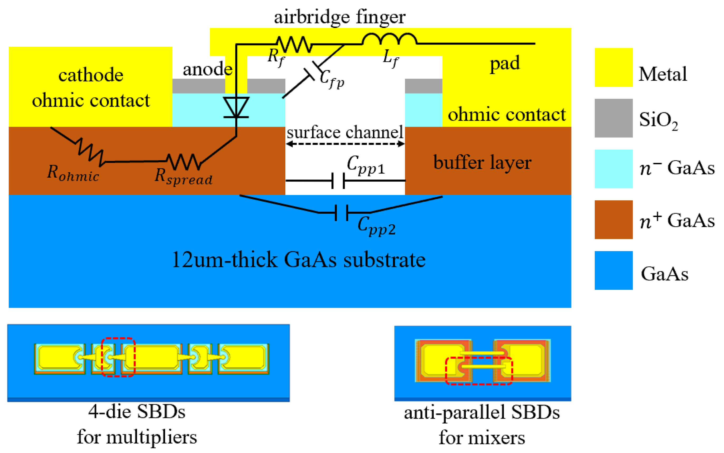
Figure 1. The cross-sectional view of the planar Schottky diode and a simplified equivalent circuit model.
Applsci 10 07924 g001
Figure 2. Schematic diagram of (a) wave port configuration of diode anode junction and (b) setup for high-frequency 3D EM simulations.
Applsci 10 07924 g002
Figure 3. Simulated optimum conversion efficiency with (a) different surface channel widths and (b) different anode junction areas.
Applsci 10 07924 g003
Figure 4. Circuit configuration of the proposed 0.34 THz tripler in HFSS.
Applsci 10 07924 g004
Figure 5. Photograph of the assembled tripler block connected with the SMA-connector for DC bias (left). Picture of the fabricated THz GaAs monolithic integrated tripler circuit installed in a split block with the enlarged view of the diode chip (right).
Applsci 10 07924 g005
Figure 6. 3D diode chip model and diode port configuration in HFSS.
Applsci 10 07924 g006
Figure 7. Circuit configuration of the proposed monolithic integrated subharmonic mixer in HFSS.
Applsci 10 07924 g007
Figure 8. Photograph of the assembled SHM block with the K-connector for the IF output (left). Picture of the fabricated THz GaAs monolithic integrated SHM circuit and assembly diagram in the split block with the enlarged view of diode chip (right).
Applsci 10 07924 g008
Figure 9. Tolerance analysis of (a) 0.34 THz tripler and (b) 0.34 THz SHM caused by a substrate assembly error. The substrate assembly position deviates from the original position ±10 μm along the x and y directions, respectively.
Applsci 10 07924 g009
Figure 10. Tolerance analysis simulation results and comparison with original simulation data of (a) 0.34 THz tripler and (b) 0.34 THz SHM.
Applsci 10 07924 g010
Figure 11. Schematic diagram of the 0.34 THz tripler’s output power test setup.
Applsci 10 07924 g011
Figure 12. Measured (a) output power and (b) frequency conversion efficiency of the 0.34 THz tripler with different input power levels from 324 GHz to 352 GHz.
Applsci 10 07924 g012
Figure 13. Performance comparison of (a) simulated and measured efficiency with 100 mW input power and (b) measured output power of three different tripler modules with 100 mW input power.
Applsci 10 07924 g013
Figure 14. Schematic diagram of 0.34 THz SHM’s noise temperature test setup.
Applsci 10 07924 g014
Figure 15. Photograph of the 0.34 THz SHM’s noise temperature test platform using Y-factor method measurement. The ambient/hot calibration load, respectively, radiates broadband noise energy related to real-time temperature into the receiver through feed horn antenna. Every time the calibration load is exchanged the under-test receiver is position fixed.
Applsci 10 07924 g015
Figure 16. Simulated and measured performances of 0.34 THz SHM from 320 GHz to 360 GHz (a) double sideband (DSB) noise temperature and (b) DSB conversion loss.
Applsci 10 07924 g016
Figure 17. Comparison of the measured DSB noise temperature of three different mixer modules.
Applsci 10 07924 g017
Table 1. Physical and electrical diode parameters of the 0.34 terahertz (THz) tripler.
Physical ParametersElectrical Parameters
Epilayer doping = 2 × 1017 cm−3Junction potential (Vj)0.9 V
Epilayer thickness = 0.3 μmZero-bias junction capacitance (Cj0)16 fF
N+ layer doping = 5 × 1018 cm−3Series resistance per anode (RS)6 Ω
N+ layer thickness = 3.5 μmReverse saturation current (Isat)2 × 10⁻¹⁷ A
Anode radius = 1.8 μmReverse breakdown voltage (Vbr)−9.6 V
SiO2 layer thickness = 0.5 μmReverse breakdown current (Ibr)−10 uA
Substrate thickness = 12 μmIdeality factor per anode (η)1.2
Chip length = 224 μm
Chip width = 28 μm
Chip height = 6.3 μm
Grading coefficient (M)0.5
Typical cut-off frequency (fT)1.5 THz
Table 2. Physical and electrical diode parameters of the 0.34 THz mixer.
Physical ParametersElectrical Parameters
Epilayer doping = 2 × 1017 cm−3Junction potential (Vj)0.9 V
Epilayer thickness = 0.1 μmZero-bias junction capacitance (Cj0)2 fF
N+ layer doping = 5 × 1018 cm−3Series resistance per anode (RS)7 Ω
N+ layer thickness = 3 μmReverse saturation current (Isat)30 fA
Anode radius = 0.55 μmReverse breakdown voltage (Vbr)−9.6 V
SiO2 layer thickness = 0.5 μmReverse breakdown current (Ibr)−10 uA
Substrate thickness = 12 μmIdeality factor per anode (η)1.2
Chip length = 220 μm
Chip width = 70 μm
Chip height = 6 μm
Grading coefficient (M)0.5
Typical cut-off frequency (fT)10 THz
Table 3. Comparison of published Schottky SHM performance in a similar frequency range.
ReferenceFrequency Range (GHz)Noise Temperature (K)Conversion Loss (dB)
[37]290–3102000–2600 (SSB)9–10 (SSB)
[38]295–345900 (DSB) (minimum)9–13 (SSB)
[39]320–360900 (DSB)9 (SSB)
This work325–352900–1500 (DSB)6–9 (DSB)
Publisher’s Note: MDPI stays neutral with regard to jurisdictional claims in published maps and institutional affiliations.